
Experimental Study on Pipeline–Soil Interaction in Translational Landslide


Abstract
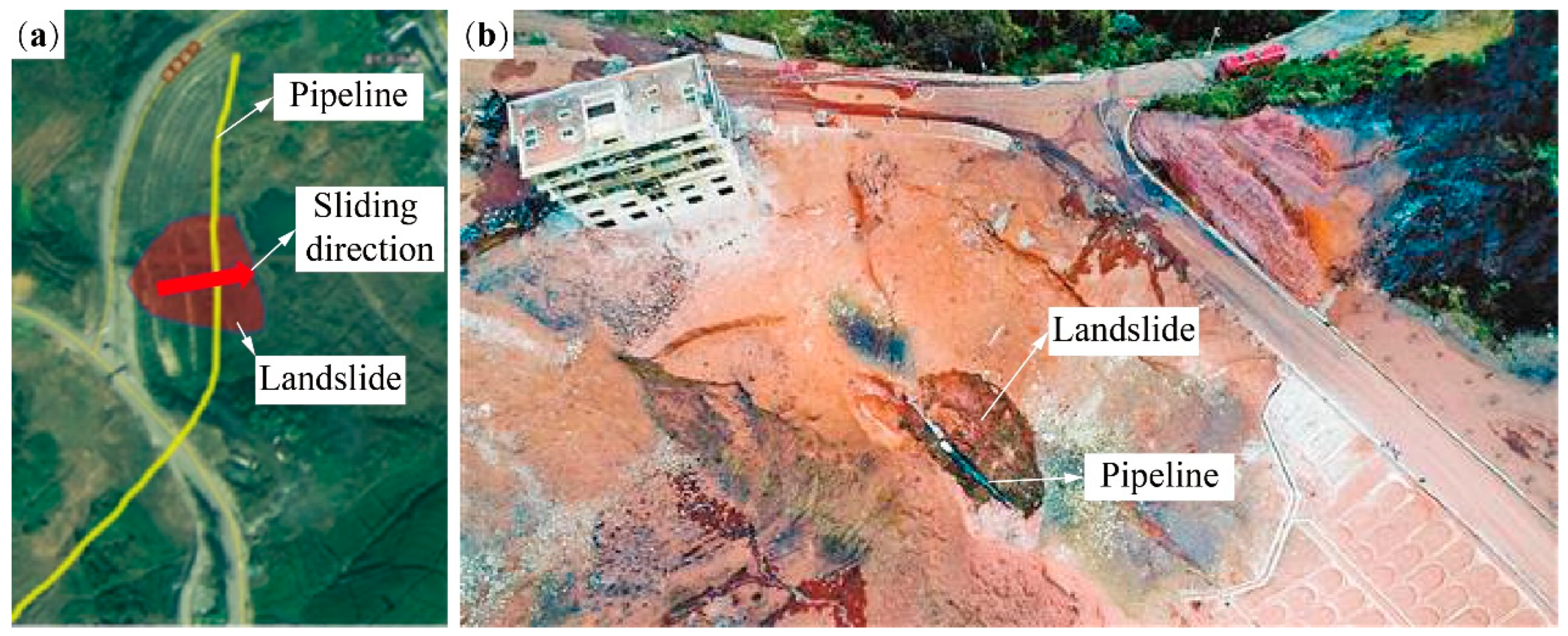
:1. Introduction
2. Experimental Section
2.1. Experimental Scheme
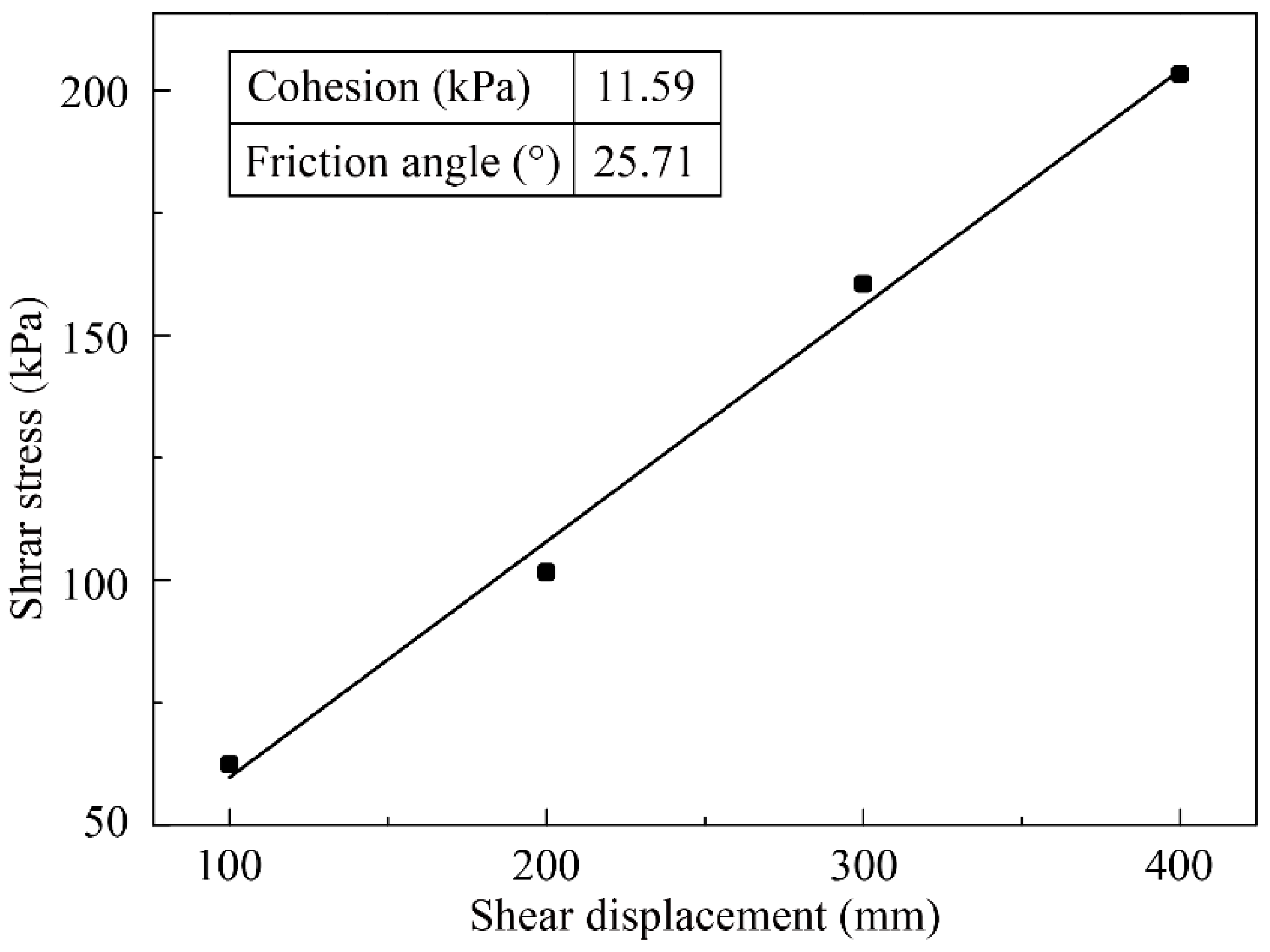
2.2. Experimental Material
2.3. Model Construction
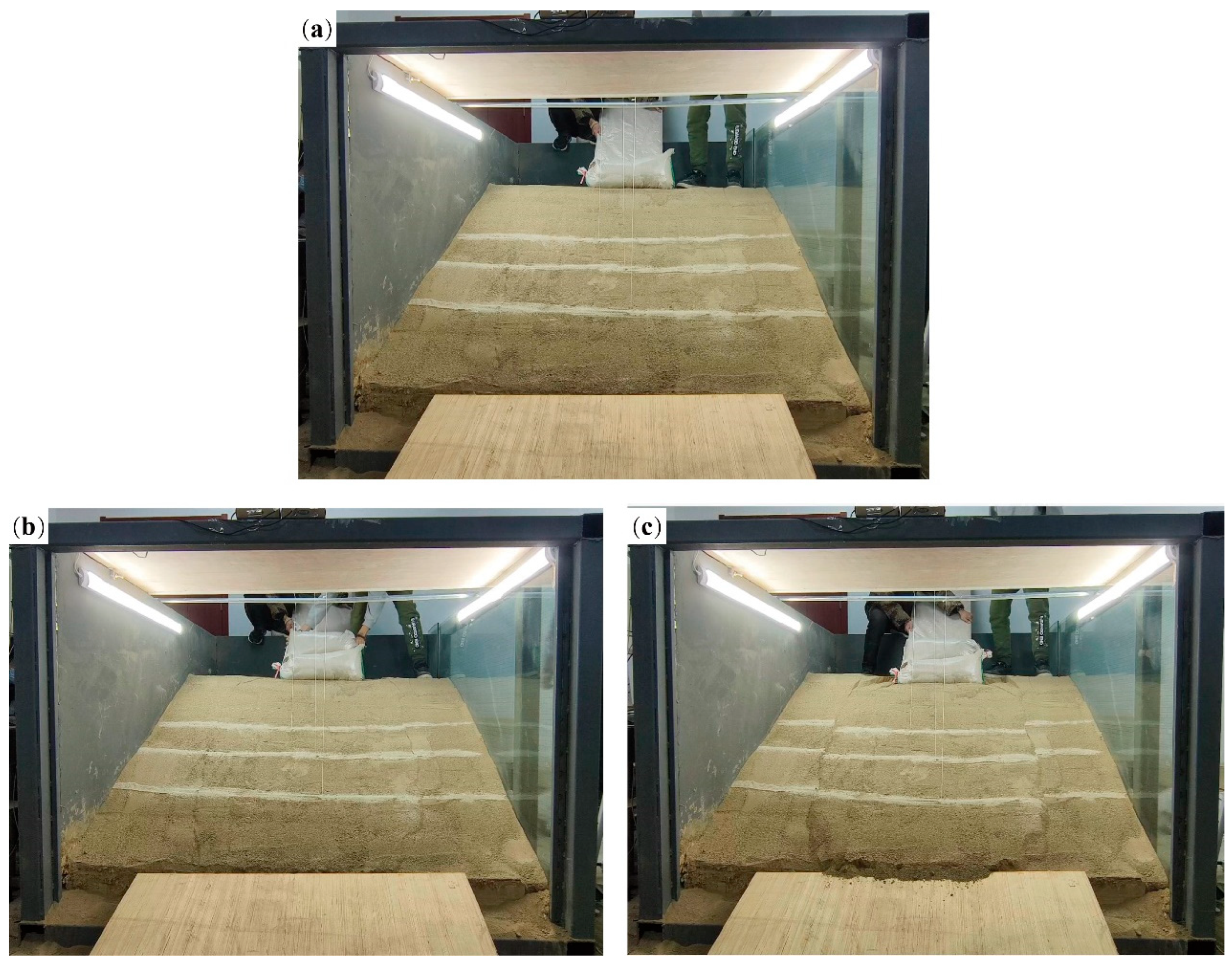
2.3.1. Landslide Model Construction
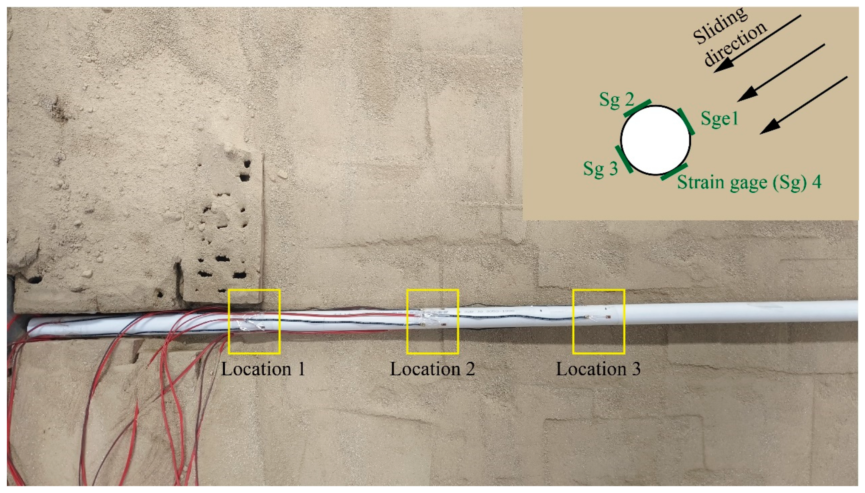
2.3.2. Measurement of Experimental Data
2.3.3. Load Application
3. Experimental Results and Discussion
3.1. Soil Response of Landslide Mass
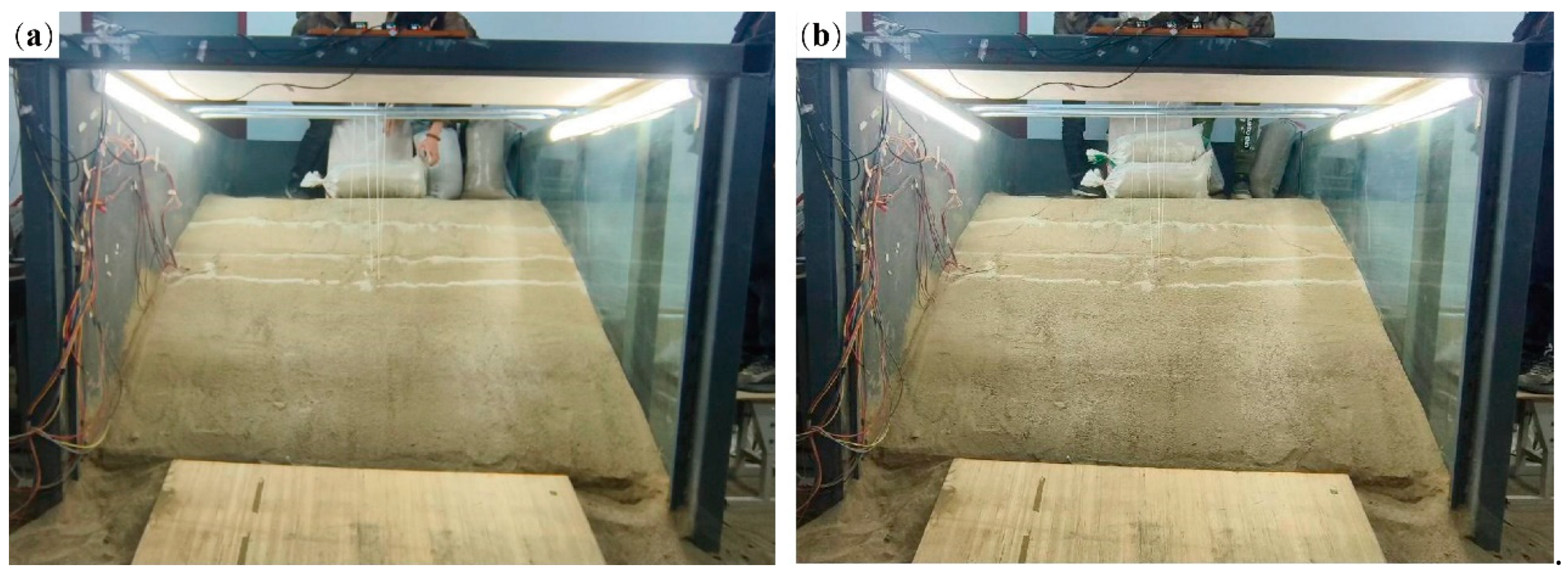
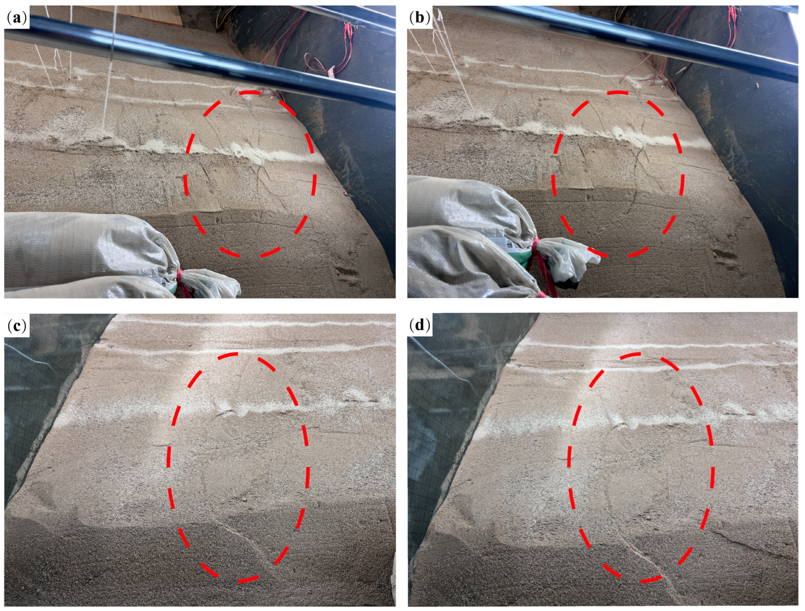
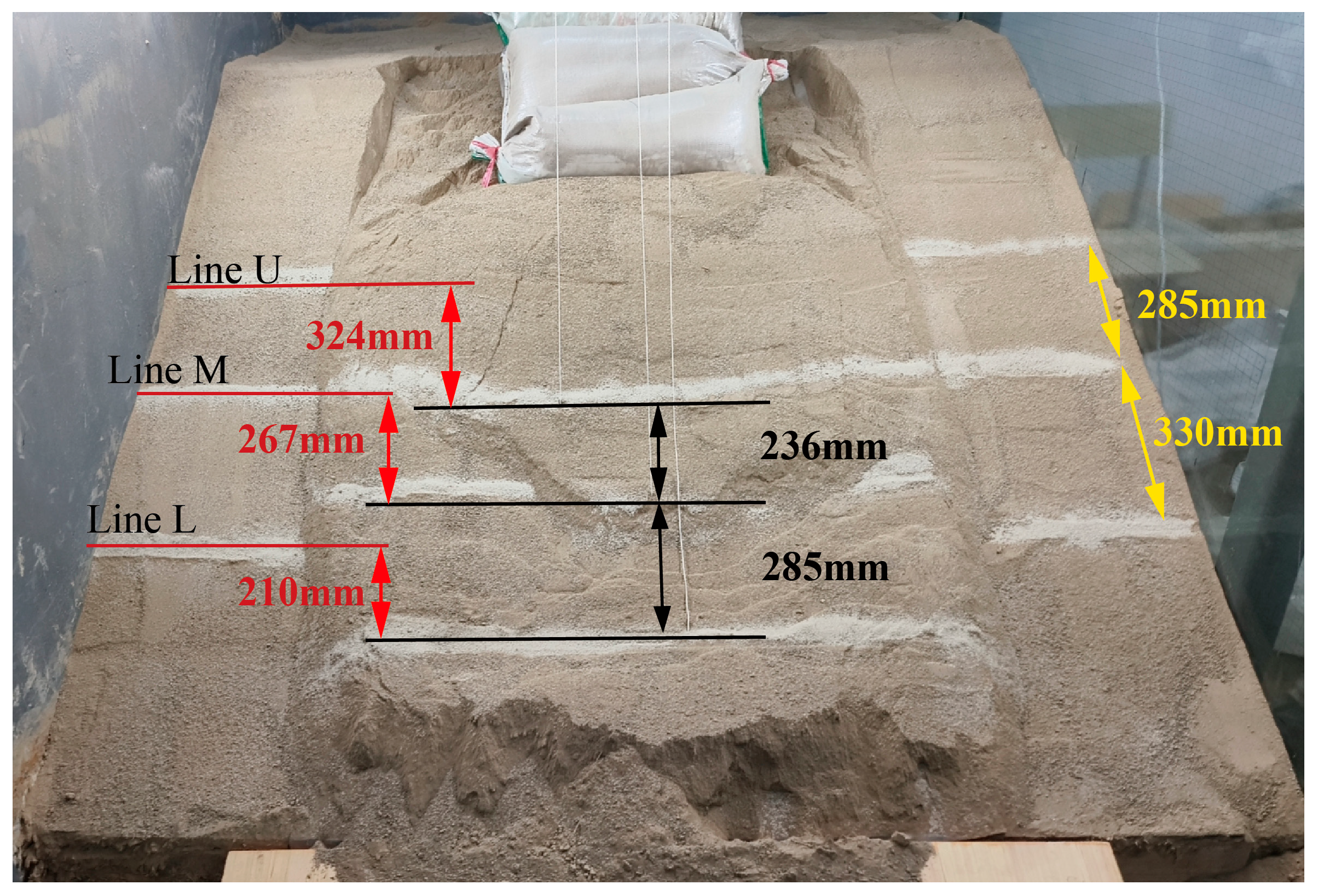
3.1.1. Development of Landslide Cracks
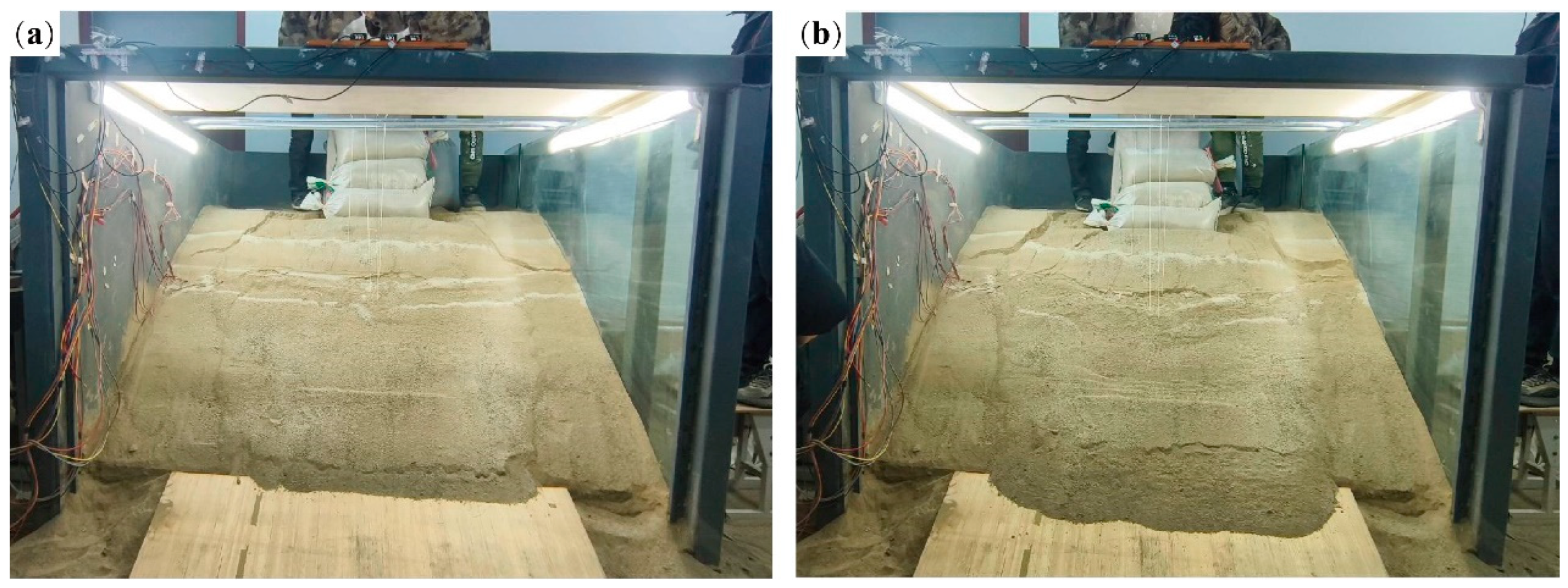
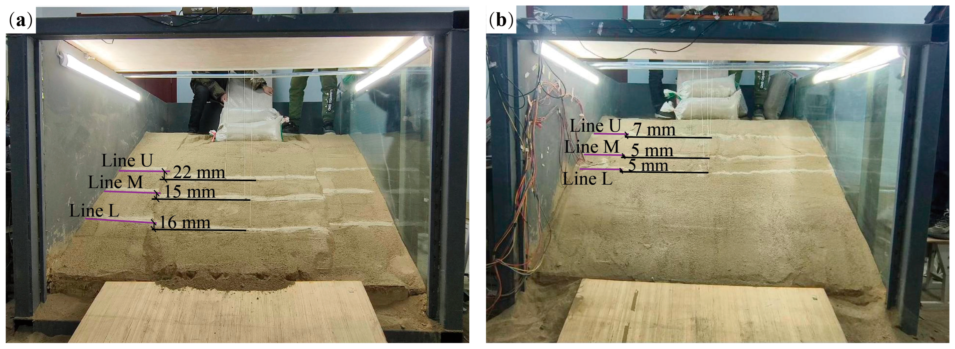
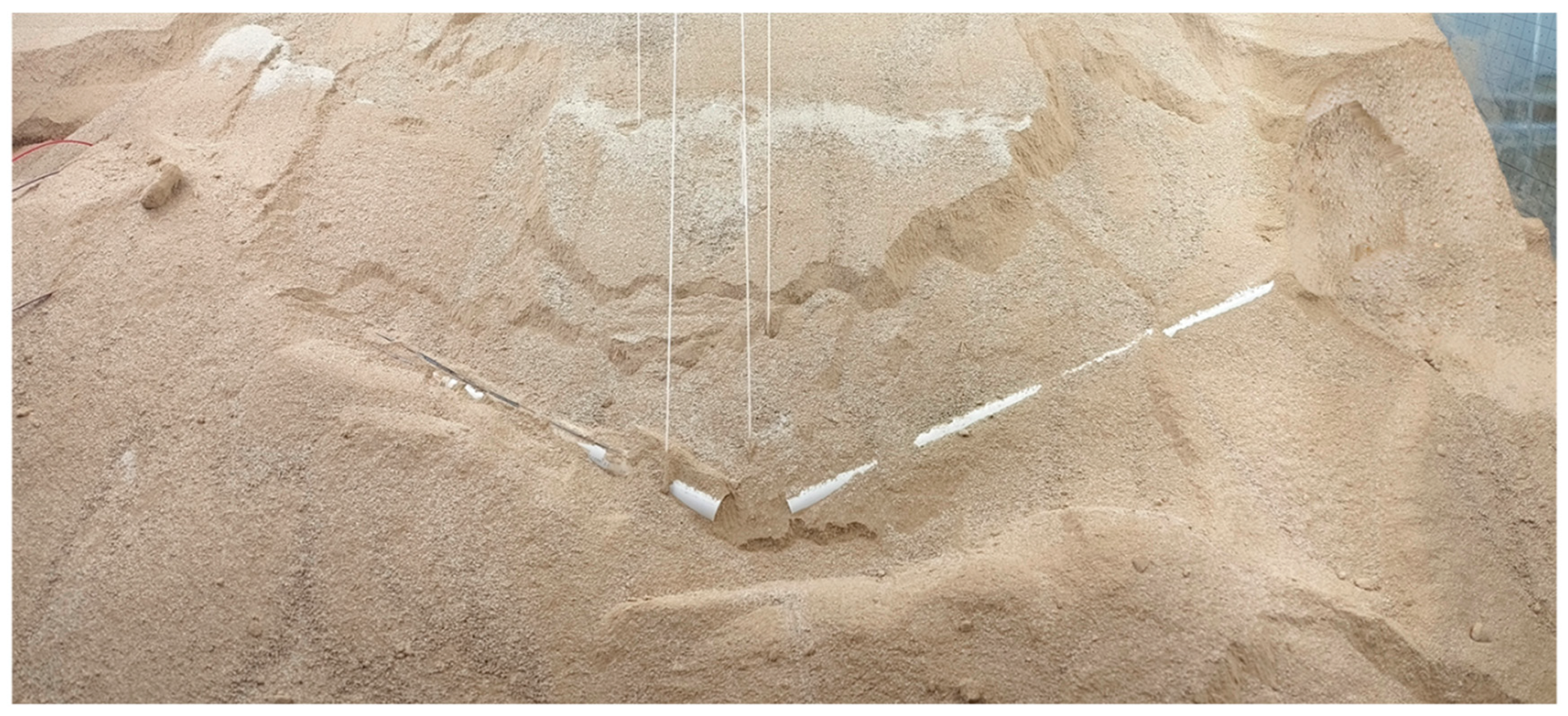
3.1.2. Mechanisms of Landslide Movement
3.2. Pipeline Response
3.2.1. The Deformation of Pipeline
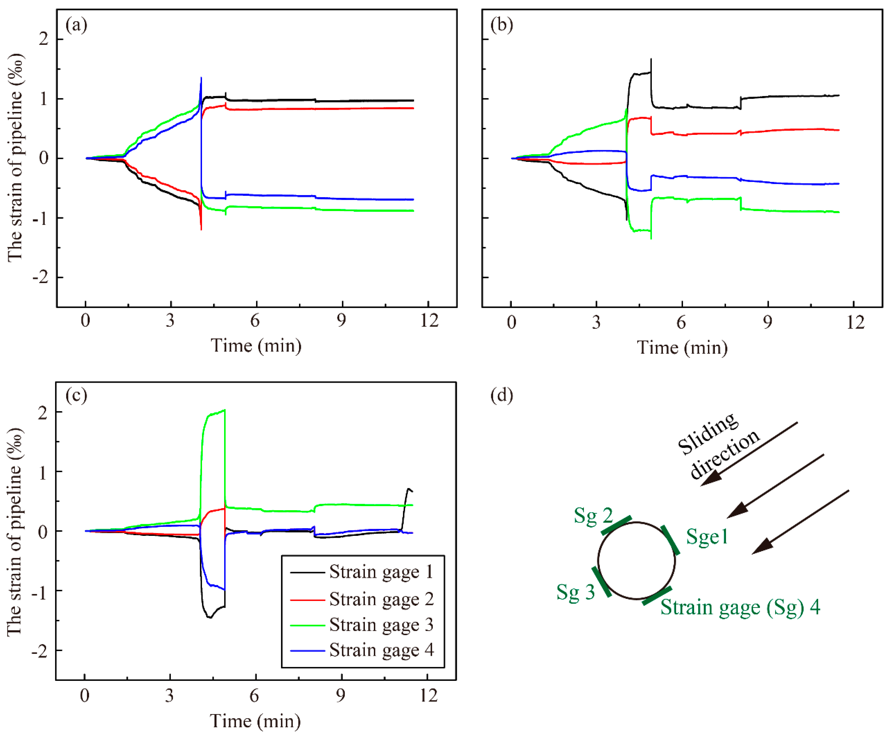
3.2.2. The Strain of Pipeline
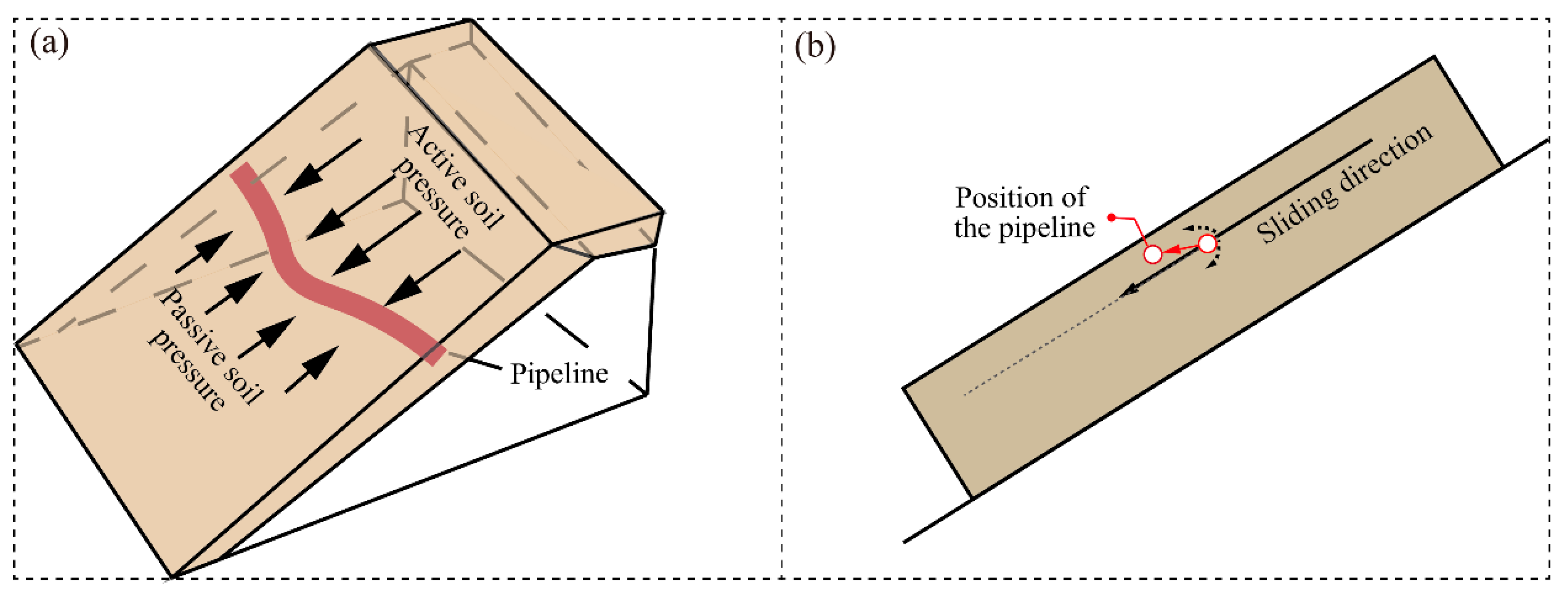
3.3. Discussion of Pipeline–Soil Interaction
4. Conclusions
- (1)
- The crack in the slope initially develops at the crest when subjected to a top load, which is subsequently followed by downward sliding. The upper sliding mass exerts a thrust on the lower stable soil, leading to the propagation of cracks toward the toe of the slope. Once a critical loading threshold is reached, the lower slope becomes destabilized due to the thrust from the upper mass, resulting in global sliding and eventual slope failure.
- (2)
- Pipelines that traverse the sliding mass are subjected to thrust loads in the direction of sliding, which results in peak strain of pipelines occurring at the midpoint of the sliding mass. This location is identified as the most susceptible to fracture of pipelines. Furthermore, shear forces at the interface between the sliding and non-sliding regions contribute to significant strain in these areas.
- (3)
- When constrained by non-sliding regions, laterally embedded pipelines behave similarly to beam structures, providing resistance against thrust, shear, and bending moments. This structural behavior increases the load threshold for slope instability, thereby enhancing the overall stability of the slope.
- (4)
- The presence of pipelines alters the evolution of landslide movement patterns. The pipeline decreases the overall sliding displacements of the sliding mass and changes the sliding direction of the sliding mass. The movements of the sliding mass divide into upward and downward movements around the pipeline. The downward movements around the pipeline exert upward pressure on the pipeline, effectively reducing its burial depth of pipeline.
Author Contributions
Funding
Institutional Review Board Statement
Informed Consent Statement
Data Availability Statement
Conflicts of Interest
References
- Huang, W.H. The development of oil and gas storage and transportation technology in China. Oil Gas Storage Transp. 2012, 31, 411–415. [Google Scholar]
- Peng, S.B.; Liao, W.; Liu, E.B. Pipe–soil interaction under the rainfall-induced instability of slope based on soil strength reduction method. Energy Rep. 2020, 6, 1865–1875. [Google Scholar] [CrossRef]
- Yan, Y.; Xiong, G.L.; Zhou, J.J.; Wang, R.; Huang, W.; Yang, M.; Wang, R.C.; Geng, D. A Whole Process Risk Management System for the Monitoring and Early Warning of Slope Hazards Affecting Gas and Oil Pipelines. Front. Earth Sci. 2022, 9, 812527. [Google Scholar] [CrossRef]
- Fa-You, A.; Chen, T.H.; Yang, C.; Wu, Y.F.; Yan, S.Q. Study on Disaster Mechanism of Oil and Gas Pipeline Oblique Crossing Landslide. Sustainability 2023, 15, 3012. [Google Scholar] [CrossRef]
- Cruz, A.M.; Krausmann, E. Vulnerability of the oil and gas sector to climate change and extreme weather events. Clim. Chang. 2013, 121, 41–53. [Google Scholar] [CrossRef]
- Xiao, J.Z.; Kong, W.C.; Wang, X.L.; Li, M. Numerical modeling and assessment of natural gas pipeline separation in China: The data from Henan Province. Pet. Sci. 2020, 17, 268–278. [Google Scholar] [CrossRef]
- Huang, W.H.; Chen, J.D.; Fu, C.; Huang, Y. Approach for natural gas to be a primary energy source in China. Front. Eng. Manag. 2019, 6, 467–476. [Google Scholar] [CrossRef]
- Niu, H.T. Smart safety early warning model of landslide geological hazard based on BP neural network. Saf. Sci. 2020, 123, 104572. [Google Scholar]
- Zahid, U.; Godio, A.; Mauro, S. An analytical procedure for modelling pipeline landslide interaction in gas pipelines. J. Nat. Gas Sci. Eng. 2020, 81, 103474. [Google Scholar] [CrossRef]
- Zhang, J.; Liang, B.F.; Pan, B.; Shen, K.R.; Chen, L.Y. Mechanical Response Analysis of Gas Pipeline under Traction Landslide. Press. Vessel Technol. 2020, 37, 19–25+38+58. [Google Scholar]
- Zhang, H.; Liu, X.B. Design strain calculation model for oil and gas pipelines subject to geological hazards. Oil Gas Storage Transp. 2017, 36, 91–97. [Google Scholar]
- Lin, D.; Lei, Y.; Xu, K.; Huang, R. An experiment on the effect of a transverse landslide on pipelines. Acta Pet. Sin. 2011, 32, 728–732. [Google Scholar]
- Feng, W.K.; Huang, R.Q.; Liu, J.T.; Xu, X.; Luo, M. Large-scale field trial to explore landslide and pipeline interaction. Soils Found. 2015, 55, 1466–1473. [Google Scholar] [CrossRef]
- Calvetti, F.; Prisco, C.; Nova, R. Experimental and Numerical Analysis of Soil–Pipe Interaction. J. Geotech. Geoenviron. Eng. 2004, 130, 1292–1299. [Google Scholar] [CrossRef]
- Lian, J.Q.; Shi, R.; Fan, R.D.; Li, X. Study on the Pipe–soil Interaction under Instability of Slope Based on Flume Experiment. J. Phys. Conf. Ser. 2022, 2381, 012060. [Google Scholar] [CrossRef]
- Guan, W.; Wu, H.G.; Wu, D.Y.; Tang, L.; Wei, H. Study on Interaction Mechanism of Natural Gas Pipe-Landslide System Reinforced by Micropile Groups Based on Model Test. Geofluids 2022, 2022, 8436297. [Google Scholar] [CrossRef]
- Katebi, M.; Wijewickreme, D.; Maghoul, P.; Roy, K. Lateral force-displacement response of buried pipes in slopes. Géotechnique 2023, 73, 375–387. [Google Scholar] [CrossRef]
- Daiyan, N.; Kenny, S.; Phillips, R.; Popescu, R. Investigating pipeline–soil interaction under axial–lateral relative movements in sand. Can. Geotech. J. 2011, 48, 1683–1695. [Google Scholar] [CrossRef]
- Zhang, W.Y.; Askarinejad, A. Behaviour of buried pipes in unstable sandy slopes. Landslides 2019, 16, 283–293. [Google Scholar] [CrossRef]
- He, W.G.; Li, H.Z.; Jia, L.L.; Yao, G.Z. Deformation monitoring and mechanism analysis on landslide along China-Myanmar Natural Gas Pipeline: Case of Shazi Town Landslide in west of Guizhou Province. Yangtze River 2020, 51, 138–143. [Google Scholar]
- Jahromi, F.H.; Jafarzadeh, F.; Zakaria, S.M. Experimental study of burial depth effect on embedded pipe deformations in sandy slopes under dynamic landsliding. Soil Dyn. Earthq. Eng. 2018, 114, 281–297. [Google Scholar] [CrossRef]
- Wang, D.Y. Study on Improvement of Pipe-Soil Spring Model in Mountain Slope Area. J. Phys. Conf. Ser. 2022, 2381, 012090. [Google Scholar] [CrossRef]
- Jiang, K.; Wang, D.; Yu, Z.F.; Huang, D. Analysis of Pipeline Damage Caused by Lateral Landslides: Taking Two Explosion Accidentsin the Qinglong Section of China-Myanmar Pipeline in Guizhou as an Example. Sci. Technol. Eng. 2023, 23, 8988–8995. [Google Scholar]
Disclaimer/Publisher’s Note: The statements, opinions, and data contained in all publications are solely those of the individual author(s) and contributor(s) and not of MDPI and/or the editor(s). MDPI and/or the editor(s) disclaim responsibility for any injury to people or property resulting from any ideas, methods, instructions, or products referred to in the content. |


| Physical Parameters | Units | Similitude Relationships | Scaling Ratios |
|---|---|---|---|
| Geometric dimensions | m | 1:30 | |
| Gravity | m/s2 | 1:1 | |
| Density | Kg/m3 | 1:1 | |
| Stress | N/m2 | = | 1:30 |
| Strain | / | 1:1 |
Disclaimer/Publisher’s Note: The statements, opinions and data contained in all publications are solely those of the individual author(s) and contributor(s) and not of MDPI and/or the editor(s). MDPI and/or the editor(s) disclaim responsibility for any injury to people or property resulting from any ideas, methods, instructions or products referred to in the content. |
© 2025 by the authors. Licensee MDPI, Basel, Switzerland. This article is an open access article distributed under the terms and conditions of the Creative Commons Attribution (CC BY) license (https://creativecommons.org/licenses/by/4.0/).
Share and Cite
Xue, T.; Liu, L.; Zhang, J.; Dai, M.; Shi, G.; Li, X. Experimental Study on Pipeline–Soil Interaction in Translational Landslide. Coatings 2025, 15, 537. https://doi.org/10.3390/coatings15050537
Xue T, Liu L, Zhang J, Dai M, Shi G, Li X. Experimental Study on Pipeline–Soil Interaction in Translational Landslide. Coatings. 2025; 15(5):537. https://doi.org/10.3390/coatings15050537
Chicago/Turabian StyleXue, Tianjun, Lingxin Liu, Jianlei Zhang, Mengjie Dai, Gengyuan Shi, and Xinze Li. 2025. "Experimental Study on Pipeline–Soil Interaction in Translational Landslide" Coatings 15, no. 5: 537. https://doi.org/10.3390/coatings15050537
APA StyleXue, T., Liu, L., Zhang, J., Dai, M., Shi, G., & Li, X. (2025). Experimental Study on Pipeline–Soil Interaction in Translational Landslide. Coatings, 15(5), 537. https://doi.org/10.3390/coatings15050537