Article

Effect of Gun Geometry on MCrAlX Coating Microstructure and In-Flight Oxidation Deposited by Low-Temperature High-Velocity Air Fuel

by
Murilo Sergio Lamana
1,
Aravind Kumar Thoutam
1,
Bruno C. N. M. de Castilho
1,
Fadhel Ben Ettouil
1,
Ritvij Chandrakar
2,
Stephanie Bessette
2,
Nicolas Brodusch
2,
Raynald Gauvin
2,
Ali Dolatabadi
3 and
Christian Moreau
1,*
1
Department of Mechanical, Industrial and Aerospace Engineering (MIAE), Concordia University, Montreal, QC H4V 1T4, Canada
2
Department of Mining and Materials Engineering, McGill University, Montreal, QC H3A 0G4, Canada
3
Department of Mechanical and Industrial Engineering, University of Toronto, Toronto, ON M5S 3H2, Canada
*
Author to whom correspondence should be addressed.
Coatings 2025, 15(3), 357; https://doi.org/10.3390/coatings15030357
Submission received: 18 February 2025 / Revised: 12 March 2025 / Accepted: 17 March 2025 / Published: 19 March 2025

Abstract

:
Aircraft gas turbine blades operate in aggressive, generally oxidizing, atmospheres. A solution to mitigate the degradation and improve the performance of such components is the deposition of thermal barrier coatings systems (TBCs). High-velocity air fuel (HVAF) is a very efficient process for coating deposition in TBC systems, particularly for bond coats in aerospace applications. However, its low-temperature variant has received little attention in the literature and could be a promising alternative to limit oxidation during spraying when compared to conventional methods. This study has the main objective of analyzing how the geometry of the low-temperature HVAF gun influences the microstructure and the in-flight oxidation of MCrAlX coatings. To that end, a low-temperature HVAF torch is used to deposit MCrAlX coatings on a steel substrate with different nozzle lengths. In-flight particle diagnosis is used to measure the MCrAlX particle velocity, and to correlate to the nozzle geometry and to analyze its influence on the final coating. The microstructure of the coatings is assessed by scanning electron microscopy (SEM) and the material oxidation is analyzed and measured on a field emission scanning transmission electron microscope (FE-STEM) equipped with focused ion beam (FIB) and by Energy Dispersive Spectroscopy (EDS).

1. Introduction

The aerospace industry aims at developing components that enhance efficiency and reduce the time between overhauls. One of the primary components under research in the aerospace industry is the gas turbine engine, the improvement of which can decrease fuel consumption and consequently reduce aircraft operation costs. Gas turbine blades operate in aggressive atmospheres with constant variations in temperature and pressure, which, in over extended operational periods, may cause structural damage to these components [1,2].
A solution to enable the base material of these components to withstand aggressive atmospheres for longer periods without structural damage is the application of coatings. The primary advantage of applying a coating is its cost-effectiveness compared to other maintenance solutions for gas turbine engines, such as part replacements or regular overhauls [3]. Additionally, the application of coatings contributes to an increase in engine operating temperature and life. Therefore, the justification for investigating coatings and deposition methods lies in their ability to enhance gas turbine efficiency and reduce maintenance costs.
Coatings commonly used to mitigate the effects of high temperature and pressure in a gas turbine are thermal barrier coatings. These coatings consist of two main layers: the bond coat (BC) and the topcoat (TC). The topcoats typically comprise a ceramic layer, with 8YSZ (yttria-stabilized zirconia) being the most common, serving as an insulating layer to reduce the temperature gradient between the gases and the base material of the turbine blade [4,5]. Between the topcoat and the base material, a bond coat is deposited to promote bonding between these two layers, aiming at protection against oxidation and hot corrosion. The bond coat is usually composed of a metallic layer of the MCrAlX type (M = Ni, Co, or a combination of both, and X = Y, Hf, Si, and/or Ta), in which Al provides oxidation resistance, and Cr ensures resistance to hot corrosion. Furthermore, the presence of the bond coat is crucial to reduce the difference in thermal expansion coefficients between the ceramic layer and the base material [6].
Oxide formation can occur in the bond coat, either during the deposition process or due to exposure to high temperatures during turbine operation. Controlled oxidation of the MCrAlX coating results in the formation of a thermally grown oxide (TGO) layer that ensures adhesion between the ceramic and metallic layers, prevents oxygen ingress into the bond coat and base material, and consequently inhibits oxidation of these layers.
The presence of oxides and the quality of thermally grown oxide formation is strongly related to the bond coat deposition process. If in-flight oxidation is present during the deposition process, the reservoir of Al necessary for controlled growth of the thermally grown oxide layer will be reduced. Therefore, the in-flight oxidation during the deposition process is not favorable for BCs, as coatings with higher oxide content will be produced, and therefore, less Al will be available to form the required α-Al2O3 TGO [7].
In early generations, atmospheric plasma spray (APS) was used to deposit coating materials such as Ni-Cr or Ni-Al with relatively simple compositions and for temperatures up to 950 °C. However, the demand for higher inlet temperatures to improve turbine efficiency made the operation environment harsher and TBC performance needed to be improved. The NiCoCrAlY coating proved to be an ideal material because of its capability to form the TGO, which is protective and beneficial to TBCs. However, the APS process has a major limitation for NiCoCrAlY bond coats, as it results in significant in-flight oxidation of the particles [8].
With the development and enhancement of high-velocity deposition systems, it was possible to deposit coatings with relatively low oxide content. The high-velocity oxy-fuel (HVOF) process has become a strong candidate and is currently one of the most used processes to generate fully dense bond coats. More recent solutions include high-velocity air fuel (HVAF) and cold spray, with both leading to decreased oxidation, and generating very dense coatings [9,10]. Nevertheless, these processes require further understanding, notably for the application of BCs.
The main difference between HVOF and HVAF is that HVAF uses air as a comburent, which promotes combustion at a lower temperature, while particles are sprayed at similar velocities. These features allow the HVAF process to deposit metallic coatings with a lower amount of oxidation. Both processes are controllable through their deposition parameters, which may generate very similar coatings in density and surface roughness [11,12].
A promising system to deposit MCrAlX material with even lower oxide content than the regular HVAF is the low-temperature HVAF system. The system is often referred in the literature as activated combustion HVAF (AC-HVAF) [13], as a graphite disk present in the back of this system is responsible to catalyze the combustion and continuously active it. Such a system operates at lower temperatures than the conventional HVAF system (1150 °C to 1600 °C) and is comparable to some extent to cold spray, as it is closer to a solid state deposition technique [14]. One of the possible setups for the low-temperature HVAF is the internal diameter HVAF (ID-HVAF), which is very efficient to deposit on the inner part of cylindrical objects, thus being useful for aerospace applications. Due to its low-temperature operation characteristics, this system can also be an alternative for additive manufacturing. However, this system is still little explored in the literature, being considered a novelty in thermal spray. There are only a few papers published for this system; therefore, fundamental work on low-temperature HVAF must still be performed.
In this study, a NiCoCrAlY commercial alloy was selected to be sprayed by low-temperature HVAF to evaluate the effect of gun geometry on bond coat formation. Additionally, microstructure and morphology of the powder was analyzed. Particle temperature measurement along with microstructural and compositional analysis were performed to have a better understanding of how the geometry influences the in-flight characteristics and the final performance of the bond coat.

2. Materials and Methods

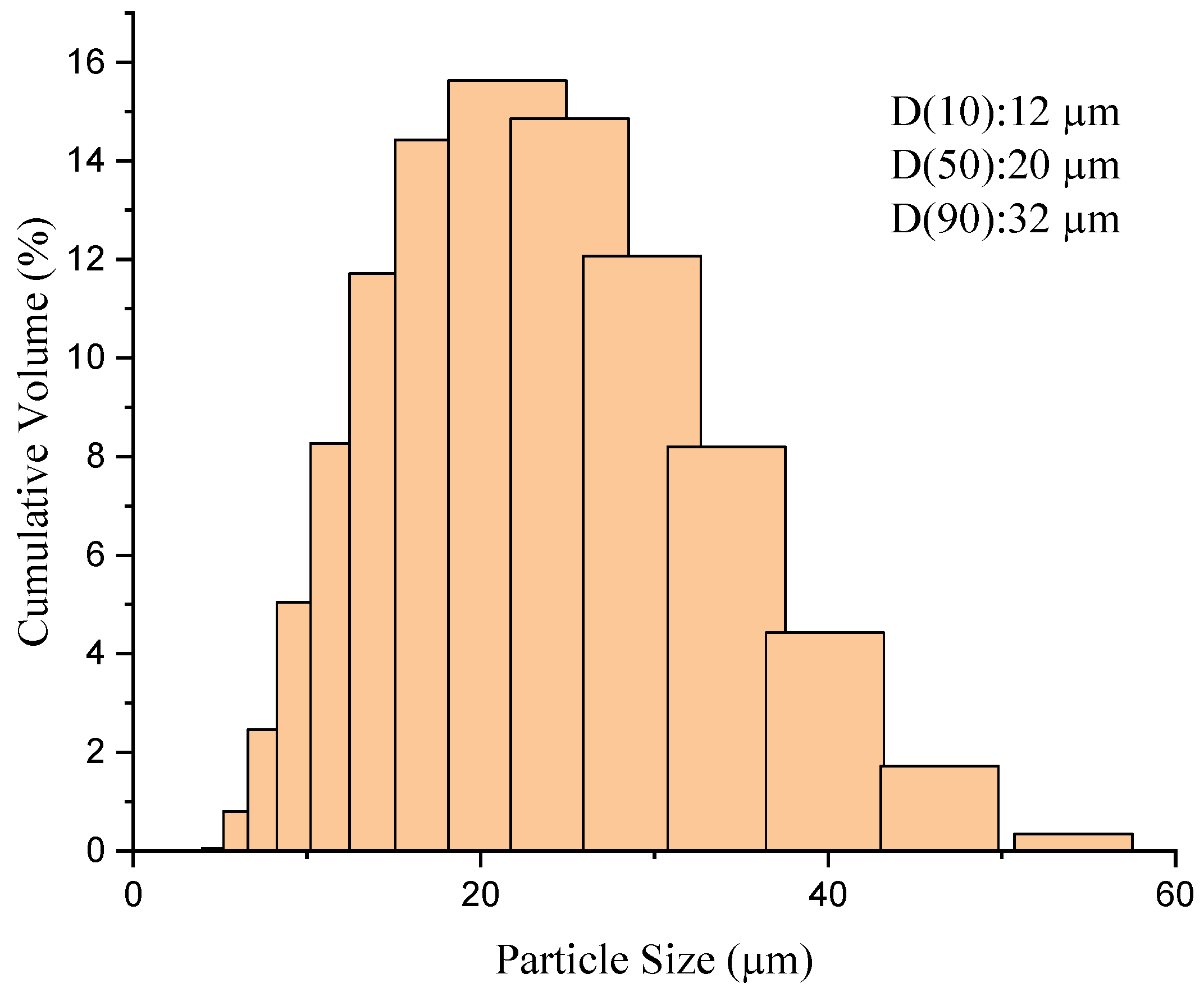
2.1. Powder Selection

For this study, a commercial NiCoCrAlY alloy, Amdry 386 (Oerlikon Metco Inc., Wohlen, Switzerland), was used. The composition of this powder and its cut size provided by the manufacturer are shown in Table 1. The powder had to be sieved, as shown in Figure 1, since the original cut size was not suitable for the low-temperature HVAF deposition system, as larger particles result in lower deposition efficiency, as they are neither thermally softened nor plastically deformed enough to adhere to the surface. The powder size distribution was analyzed after sieving by a Spraytec Laser Diffraction system (Malvern Panalytical, Worcestershire, UK). The obtained powder showed a D(10) of 12 µm, a D(50) of 20 µm and a D(90) of 32 µm. The sieved powder was sprayed onto stainless steel substrates measuring 2.54 cm × 2.54 cm. The substrates were grit blasted with alumina grit of grade 20, to an average roughness (Ra) of about 5 µm.

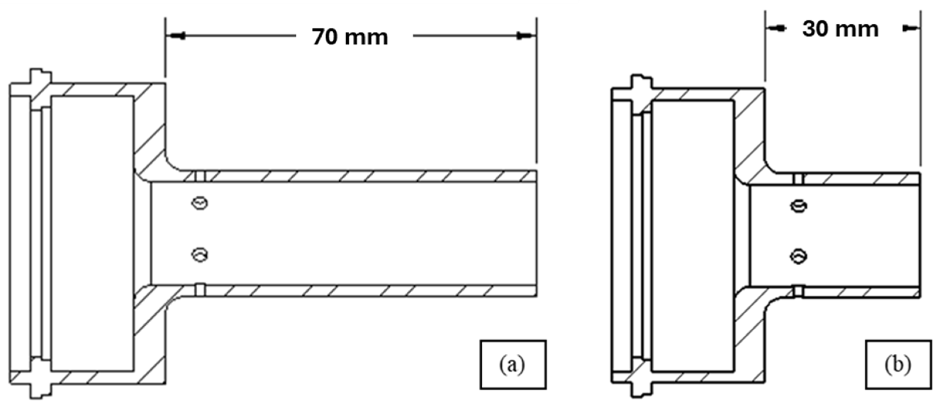
2.2. High-Velocity Air Fuel Deposition

A low-temperature HVAF system, more specifically the i7A spray torch (Uniquecoat Technologies LLC, Oilville, VA, USA), was used to deposit the NiCoCrAlY coatings. Several factors can impact the final coating quality, performance, and microstructure, such as the hardware configurations of the deposition system, that affect gas flow, particle temperature, and velocity. According to the manufacturer, the geometry of the i7A system can be varied in terms of combustion chamber, powder injector, and nozzle length, so the desired microstructure can be achieved. Altogether, two different nozzle lengths, according to Figure 2, were used, with the parameters described in Table 2. The nozzles varied in length only, having the same entry and exit diameter. A squared combustion chamber and a powder injector with a 2.4 mm diameter were used to deposit the coatings. The regulation of air, fuel, and carrier gas inlets is managed via a control console integrated with a touch-screen operator interface. A V4TM volumetric powder feeder (Uniquecoat Technologies LLC, Oilville, VA, USA), controlled through the same console, was utilized. In this study, propylene served as the fuel, while compressed air was used as the oxidant. For the deposition, the HVAF torch was moved perpendicular to the substrate surface and in steps to cover the whole sample.

2.3. Particle Diagnosis

Particle diagnoses were conducted prior to coating deposition, using a DPV evolution sensor (Tecnar Automation Ltee, Saint Bruno, QC, Canada). DPV consists of a system that measures the temperature, velocity, and diameter of individual particles in the flame [15]. The in-flight particle information was implemented to understand how particle velocity and temperature can affect the deformation and the composition of the deposited coatings.

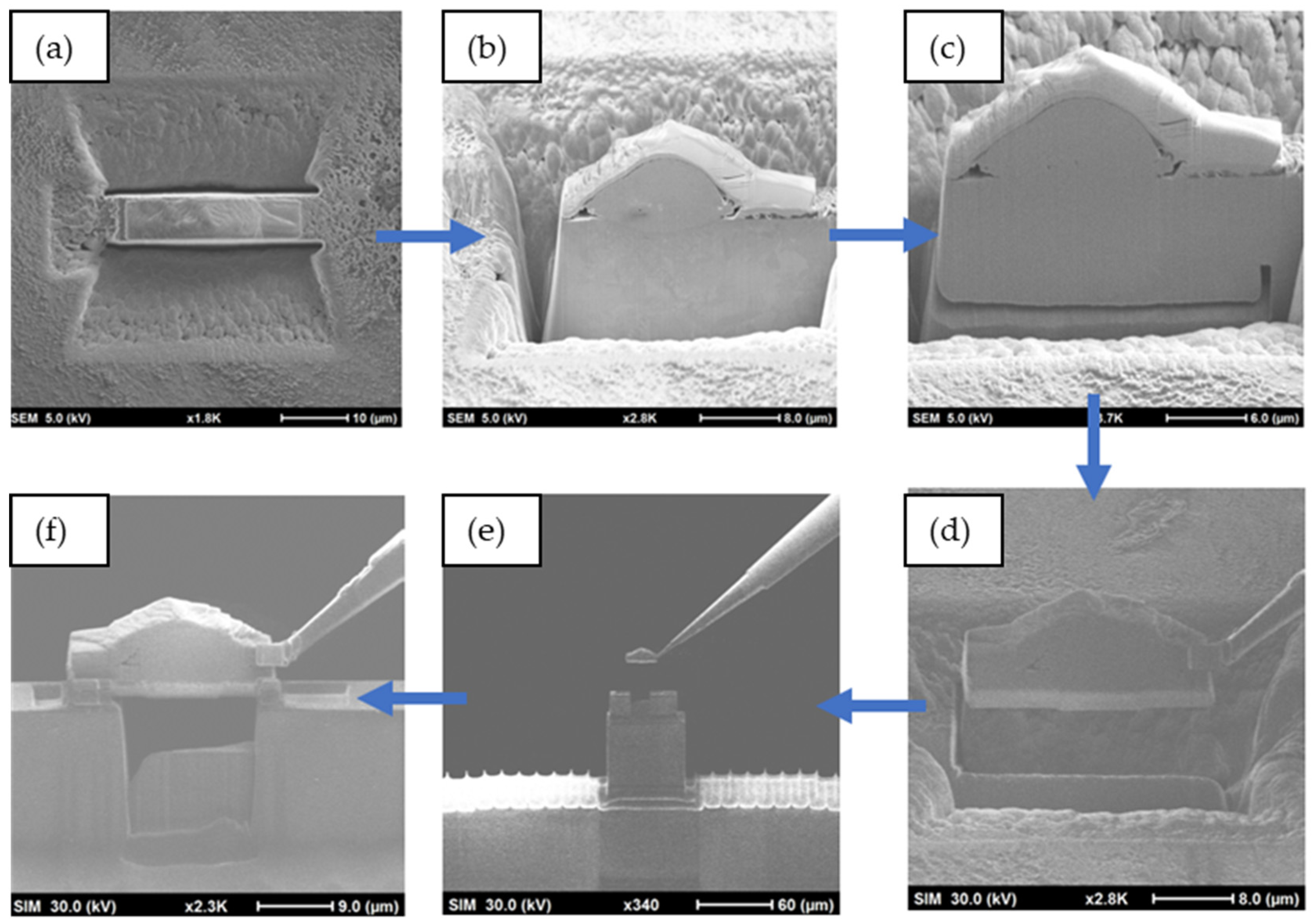
2.4. Characterization Techniques

Powder and coating microstructure characterization were performed by SEM, with both BSE (backscattered electron) and SE (secondary electron) imaging. The cross section of the Amdry 386 particles and of the deposited coatings was obtained by mounting the powder in resin, followed by grinding and polishing of the samples. The samples were ultrasonically cleaned with acetone and dried before analysis. The samples were analyzed topographically using a S-3400N SEM (Hitachi Ltd., Tokyo, Japan) equipped with EDS for elemental mapping. An analysis of the porosity and thickness of the samples was performed through ImageJ software (Version1.53k). Five different images of different locations were used, with both 500× and 1000× magnification. The deposition efficiency was determined by calculating the mass of particles sprayed, using the powder feed rate and the time the robot spent in front of the sample during deposition. By dividing the mass of particles sprayed by the final mass of the coating, the percentage of material effectively deposited on the substrate was calculated.
To investigate the oxide layer, a lift-out sample was prepared from the bulk sample using a standard lift-out technique [16] in a Hitachi Ethos NX5000 FIB-SEM (Hitachi Ltd., Tokyo, Japan) equipped with a Ga ion FIB source. The first step of the preparation was to apply a 1μm layer of platinum using beam-assisted deposition with a gas injection system (GIS) to protect the region of interest from Ga beams and prevent curtaining on the cross sectioned faces by providing a smooth surface, as demonstrated in Figure 3. After the application of the protective Pt layer, milling was carried out with an accelerating voltage of 30 KeV and a current of 45 nA. Trenches were milled on the front, back, and sides of the selected region of interest as well as below the lamella, leaving only a small portion of the coating attached to the bulk. A tungsten needle was welded to the lamella before the final milling steps to detach the lamella from the bulk sample. The lamella was then placed and welded onto a half grid; an example is shown in Figure 4d–f. The final polishing of the front face of lift-out sample was conducted in two stages: first polishing was performed with a current of 12 nA and the second stage polishing was performed with 3.5 nA to provide an even smoother surface free of topography for EDS analysis [17].
After the lift-out, EDS maps were collected using the Hitachi SU-9000 SEM equipped with an Extreme windowless EDS detector from Oxford Instruments (Oxford Instruments, Abingdon, UK). The windowless construction and high solid angle of the detector enables it to detect low energy x-rays with high efficiency.
The EDS analysis was performed on all the samples at an accelerating voltage of 2.5 KeV, emission current of 30 μA, and native resolution of 2048 using Oxford Instruments Aztec software. The oxide thickness measurements were carried using ImageJ software. The quantification of the X-ray maps was carried out using the quantification tool implemented in the Aztec software based on the factory standards and the beam normalization using a pure silicon sample [17].

3. Results and Discussion

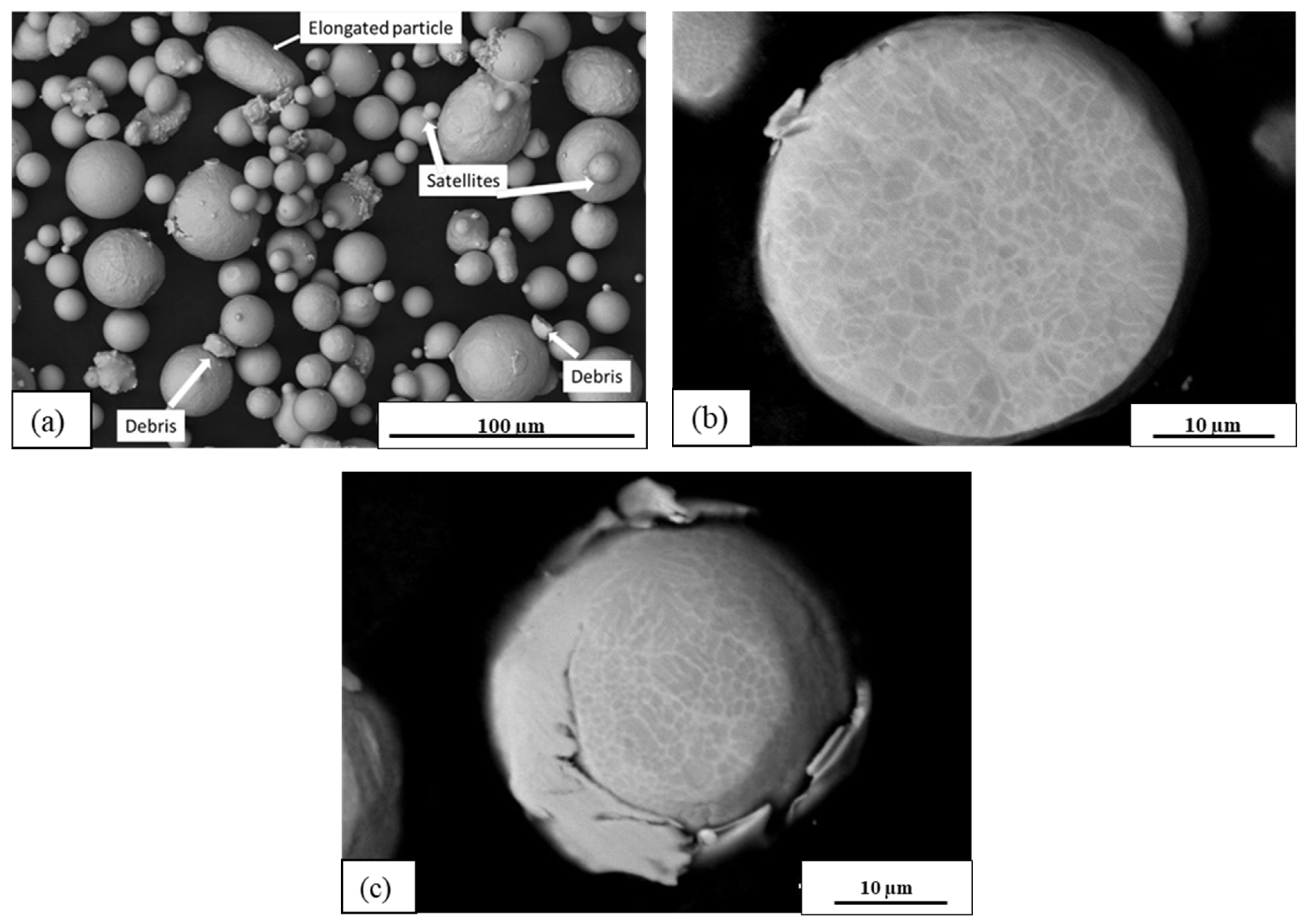
3.1. Powder Characterization

The morphological characteristics of Amdry 386 were subjected to analysis through SEM, as depicted in Figure 5a. The gas atomized (GA) powder exhibits a spheroidal morphology, featuring elongated particles with a cylindrical shape, satellites characterized by smaller particles adhering to larger particles, and the presence of attached debris. The occurrence of satellites aligns with established observations in GA powders, as documented in the existing literature [18,19,20]. It is important to mention that the presence of debris and elongated particles introduces a non-trivial aspect, and the origin of these features remains unclear, whether stemming from the gas atomization process or subsequent sieving procedures.
Additionally, powder cross sectional imaging, illustrated in Figure 5b, was conducted to facilitate the examination of the microstructure of the powder and the visual identification of distinct phases. It is noteworthy that the darker phase corresponds to a β-phase (NiAl), while the brighter phase corresponds to a γ-phase (Ni/Co) [21,22]. Both phases assume a critical role in high-temperature oxidation processes, contributing to the formation of a protective α-Al2O3-rich (TGO) layer [23]. In Figure 5c, another aspect of GA powder is demonstrated in the particle cross section, with a particle embedded on top of the other.
The oxygen content and oxide layer thickness were assessed for the feedstock material, with an average oxygen content of 4.94.9 ± 3.3 wt.%, and an oxide layer thickness of 13.6 ± 2.4 nm for the Amdry 386 powder.
In general, the features described in Figure 5a,c are not of concern when it comes to deposition processes with higher temperature deposition, such as HVOF, as the particles will melt during the in-flight. However, for low-temperature processes, such as HVAF, cold spray, and additive manufacturing, these features can be reflected in the coating, causing defects and impacting the performance [24]. It is noted that there is a significant amount of oxygen already present in the feedstock. Specifically for bond coats, at elevated temperature applications, it can be an initiator of the oxide growth, as the presence of spinels and other previously formed oxides will minimize the TBC lifespan [25].

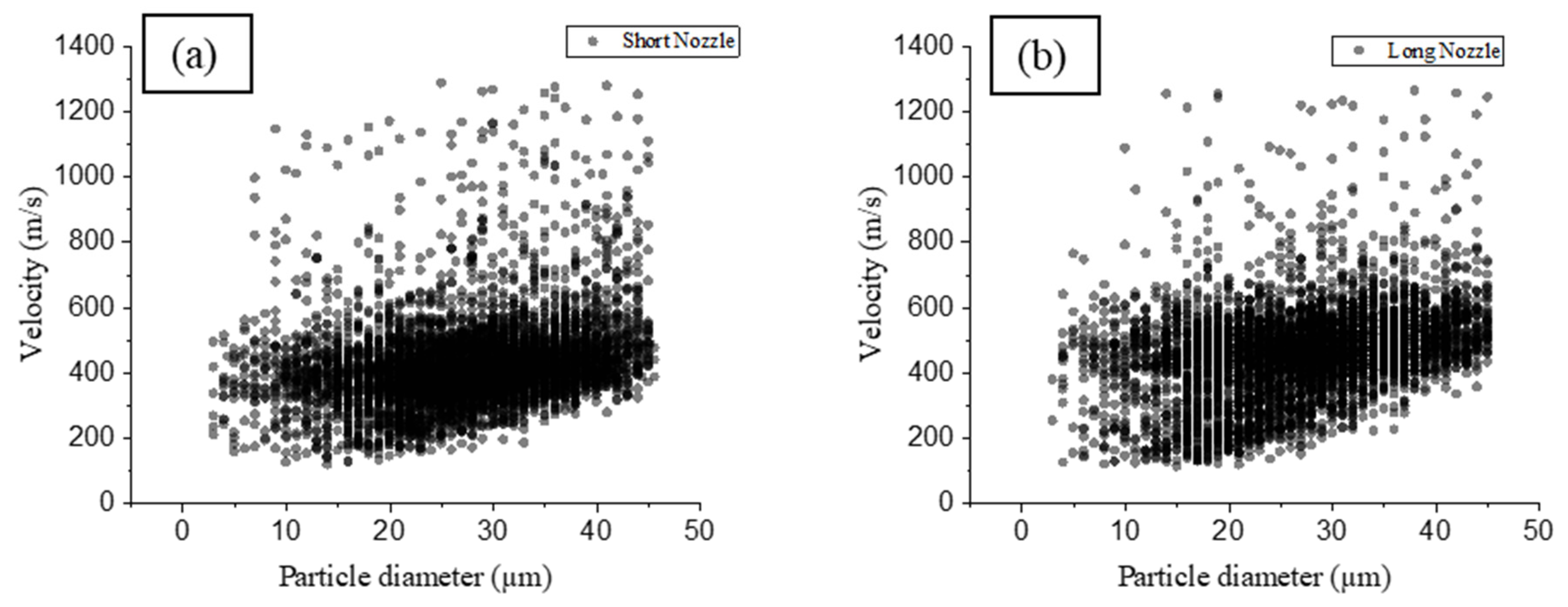
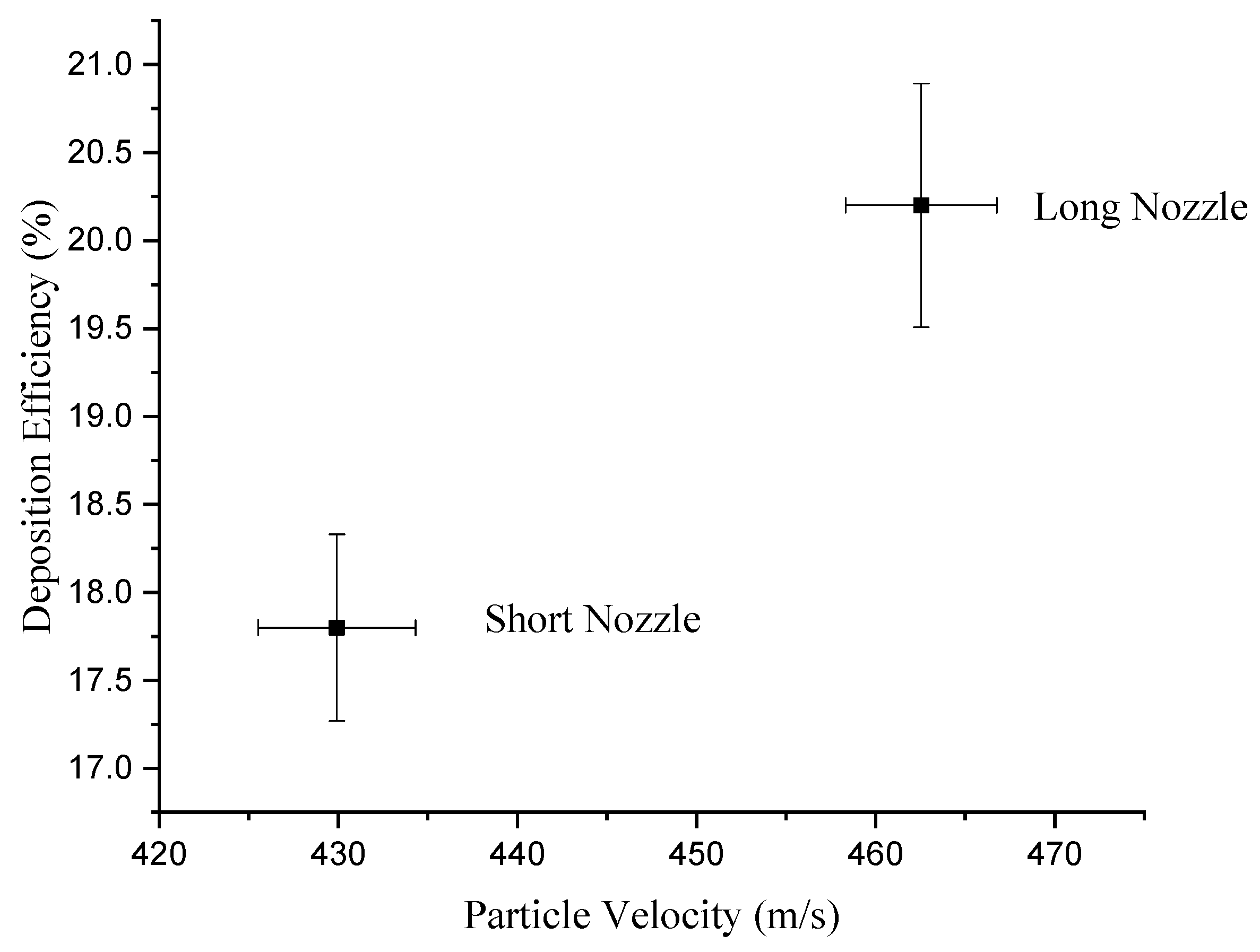
3.2. Particle Diagnostics

The characterization of particle diameter and velocity was conducted utilizing the DPV system during spraying, with the parameters outlined in Table 2, with a variation in nozzle length of the HVAF gun. Typically, the DPV sensor can discern the temperature of individual particles in the flame, provided their thermal radiation falls within the visible range (0.4–0.7 µm). In instances where particle temperatures are not high enough for radiation emission in this range, the system is equipped with laser illumination to facilitate particle detection and the determination of velocity and diameter only. Given the substantially lower temperature of the low-temperature HVAF in comparison to conventional combustion deposition processes, temperature data acquisition was not feasible. Consequently, the DPV system exclusively captured particle velocity and diameter data, as depicted in Figure 6.
A higher average velocity of 462 ± 4 m/s was observed when the long nozzle was used, as opposed to 430 ± 4 m/s for the short nozzle. Based on the numerical analysis conducted in the literature for the HVAF thermal spraying process [26], it is noted that the length of the divergent section of the nozzle has an impact on particle temperature, increasing for a longer nozzle, as the particles stay in the flame flow for a longer time. However, the velocity is very similar for different nozzles varying in length. The particle diameter versus velocity data demonstrated in Figure 6 help to provide a better overview of the particle characteristics prior to deposition. The darker the spots, the more the number of particles in that velocity range.
Although the particle diameters versus velocity distributions were similar for both cases, it is possible to notice a higher number of particles above 800 m/s when the short nozzle is used for spraying. The number of particles reaching 800 m/s and above for the short nozzle is 40% higher than the long nozzle. This can have a positive effect on the coating porosity, as high-velocity particles can densify the coating, as described in the literature for cold spray of Al coatings [27].

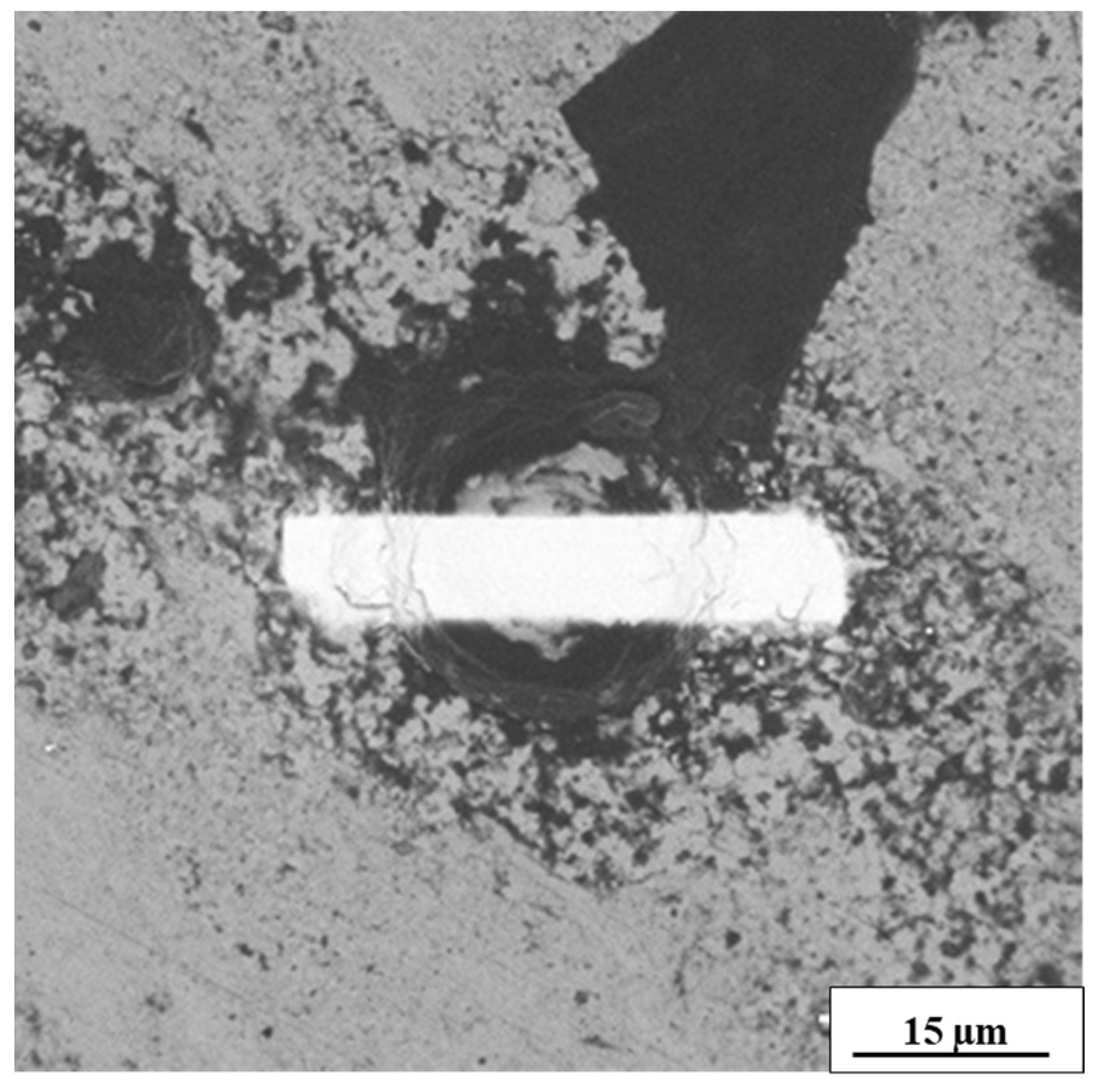
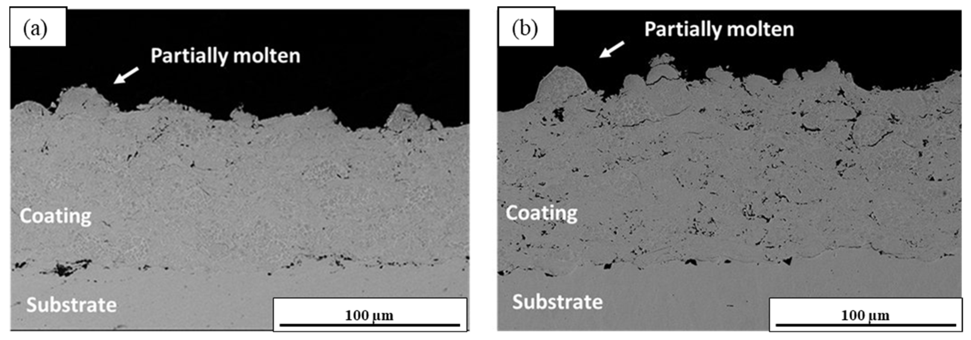
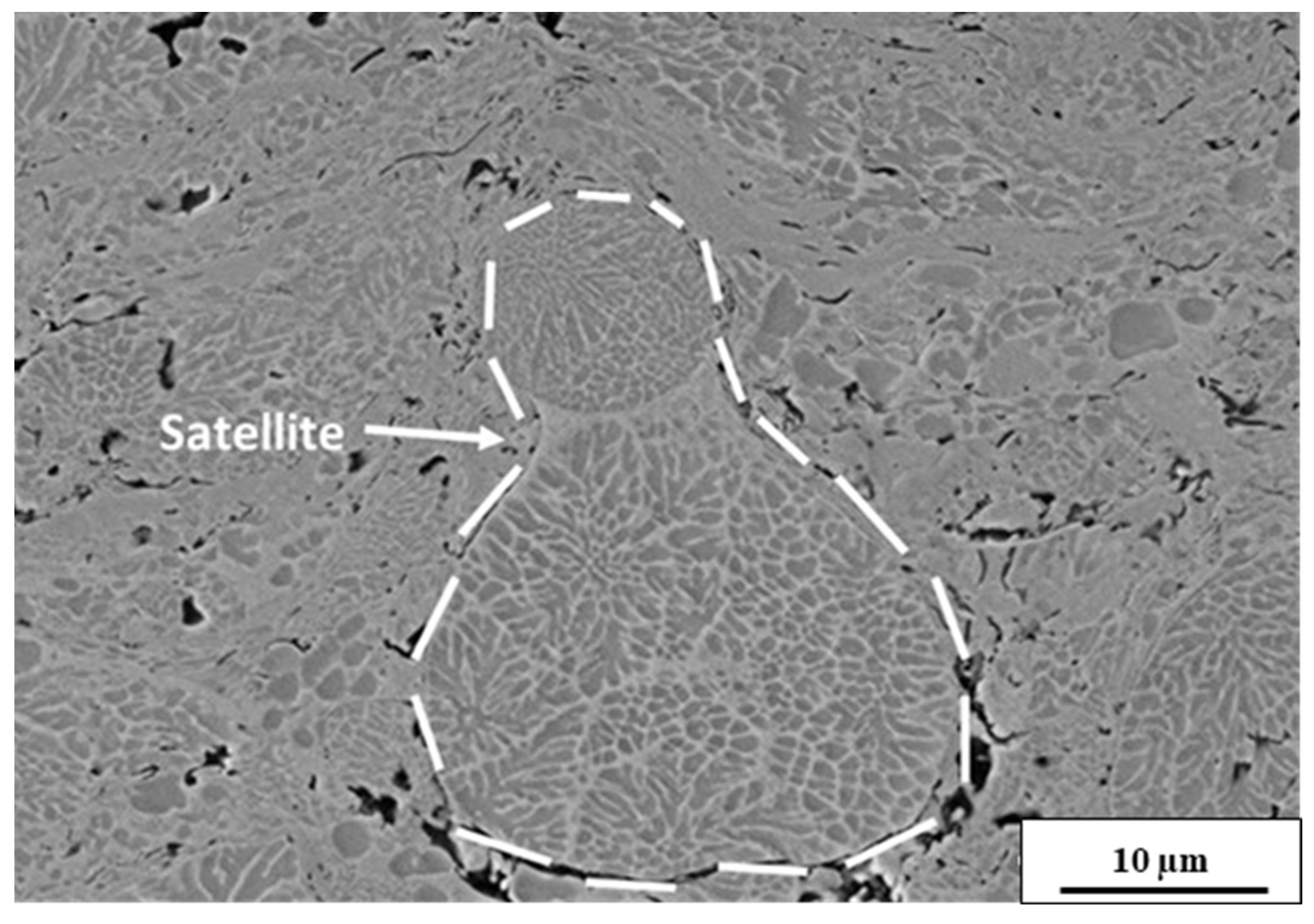
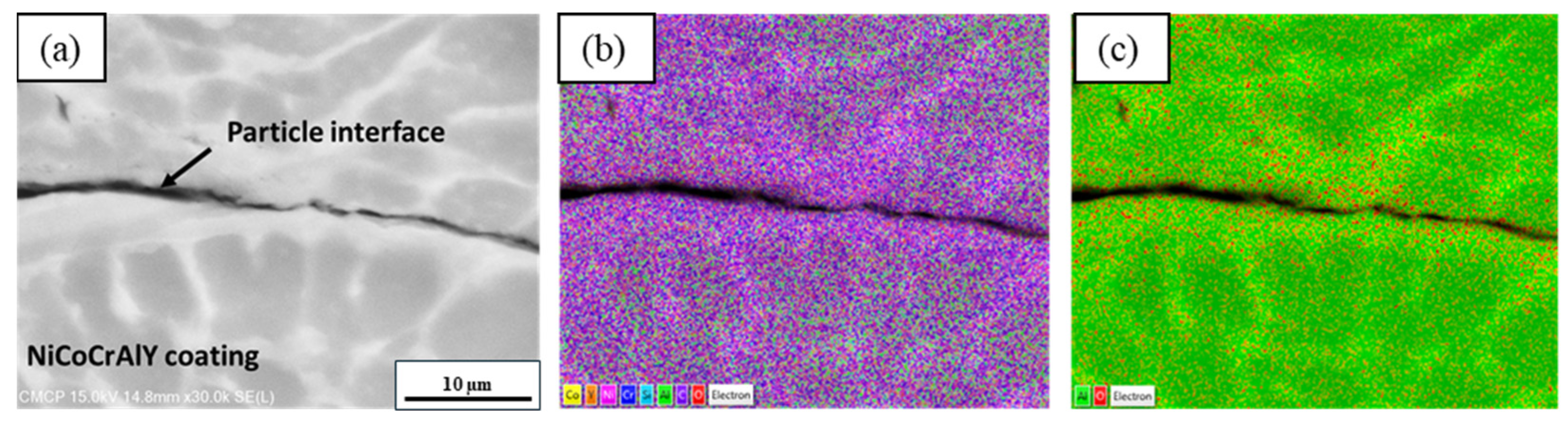
3.3. Microstructural Analysis

The deposited coatings were characterized via SEM, and their microstructure is presented in Figure 7a,b for short and long nozzle lengths, respectively. For both coatings, the presence of partially molten/slightly plastically deformed particles is observed, while keeping the spherical shape from the powder.
With the low-temperature HVAF system, particles with larger diameters (above 20 µm) generally remain unmolten or partially melted, showing the same phases present in the powder (Figure 5b). The features present in powder are also present in the coating, as shown in Figure 8. As low-temperature HVAF operates closer or just slightly above the melting temperature of the material, large particles remain in the solid state. The difference in melting grades (unmolten, partially melted, and fully melted) for different particle diameters was described in the literature for conventional HVAF [28]. This will also have an impact on surface roughness and porosity of the coating.
It is possible to verify that the coating deposited with the long nozzle is more porous than the one deposited with the short nozzle. Both coatings show higher density closer to the substrate and more pores closer to the surface.
The quantified porosity for the coating produced by the short nozzle is 1.0 ± 0.5% while for the long nozzle, it is 2.0 ± 0.1%. Higher porosity in the coating deposited by the long nozzle may be explained by the large diameter particles that are deposited with this nozzle. For the short nozzle, large diameter particles may not be deposited, as they do not have enough momentum to plastically deform. In such cases, the high diameter particles may promote a peening effect and rebound, not remaining in the coating. This situation can be confirmed by the particle diameter versus velocity depicted in Figure 6, and calculating the deposition efficiency of the coatings, as presented in Figure 9, which represents the mass of sprayed particles to the total mass of the sprayed powders. The thickness of the coatings is also related to the deposition efficiency in this graph. As expected, the deposition efficiency is directly proportional to how thick the coating is.
As the long nozzle promotes higher residence time in the flame for the particles, the heat transfer is higher than the one promoted by the short nozzle and the particles arrive at the substrate with higher temperature. The high diameter particles are then deposited, and the deposition efficiency is higher than the one sprayed with the short nozzle. Therefore, for the short nozzle, the mechanism of deposition relies mainly on the plastic deformation of the particles, being deposited almost at a solid state, while the long nozzle presents slightly higher temperature along with plastic deformation. Similar results for an activated combustion HVAF system were described in the literature [26].

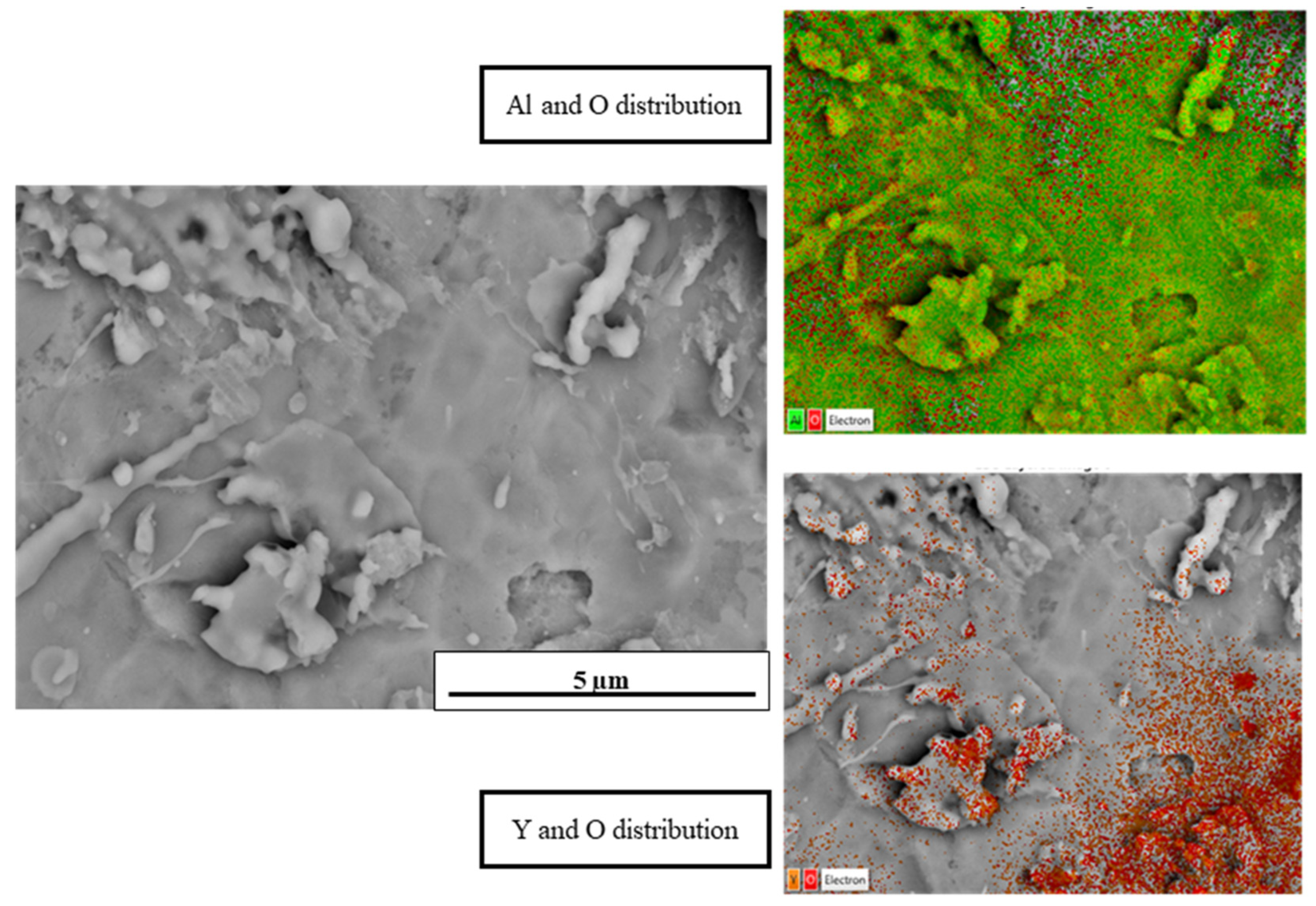
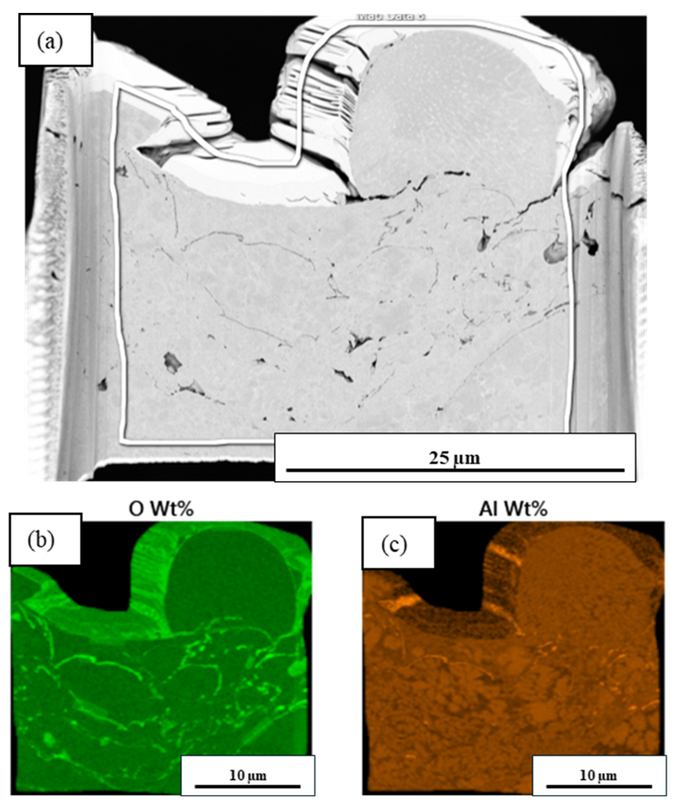
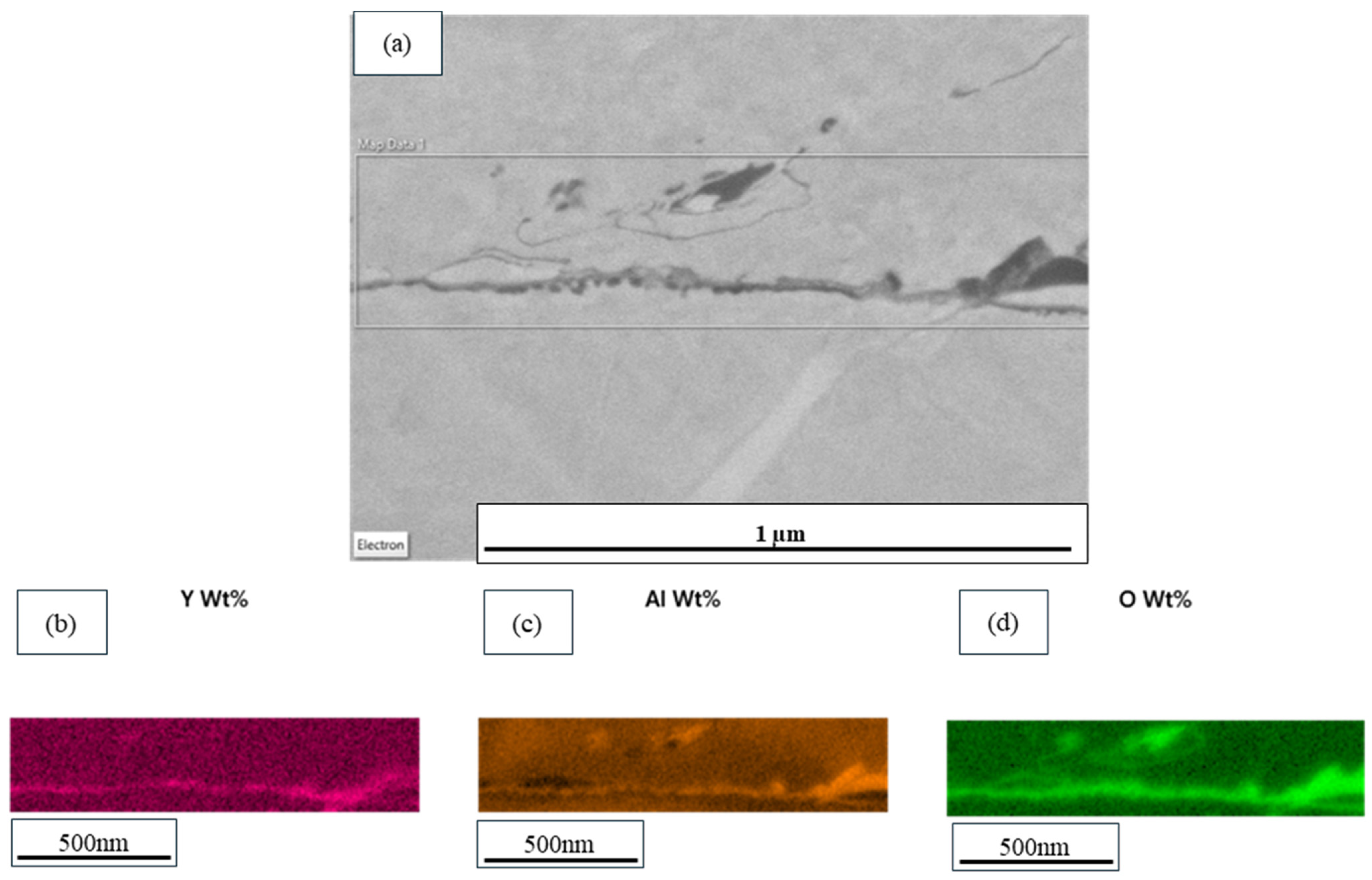
3.4. Compositional Analysis

The compositional analysis performed at low magnification on the surface of the coatings did not show any significant traces of oxidation for either the short or long nozzle. However, at higher magnification, some traces of both Al and Y oxides were present at the top surface, as indicated in Figure 10.
Having no traces of oxidation at the surface can indicate that the in-flight oxidation for the low-temperature HVAF process is minimized, as the particles deposited at the final layer do not show significant oxygen content. However, the surface analysis is not enough to conclude that in-flight oxidation was not present. Therefore, a compositional analysis of the cross section of the coating was performed, as shown in Figure 11.
At the higher magnification, it was possible to detect traces of oxidation at the particle interface (Figure 11c), although in very small amounts. Therefore, a measurement of the oxide layer was supplementary selected to compare the oxidation in the coatings obtained with different nozzles. Subsequently, to have an accurate evaluation of this layer and oxide content, thin lift-out samples were collected and analyzed in an ultra-high-resolution SEM, and composition was investigated with a windowless EDS.
For the long nozzle, shown in Figure 12, it is possible to verify the presence of oxygen and aluminum, suggesting the formation of Al2O3 in specific regions of the sample. In bond coats, for high-temperature applications, the formation of an Al2O3 layer is expected; however, the formation of yttrium, in the form of fine oxide precipitates, was also reported in the literature [29,30]. For the short nozzle, shown in Figure 13, the same behavior was observed, with aluminum oxides detected.
To evaluate the remaining oxide compositions, the accelerating voltage of the EDS detector needed to be changed from 2.5 to 4 KeV, so a wider range of materials could be detected. With this technique, it was possible to confirm that yttrium is present and matching with oxygen, as shown in Figure 14, and as previously observed in the literature [29,30]. Therefore, the oxides formed in the coating are mainly composed of aluminum and yttrium.
To assess the in-flight oxidation of both coatings, the oxide layer thickness and average oxygen content was measured and reported in Table 3.
The coating deposited with the short nozzle had a slightly higher oxide layer thickness and average oxygen content than the coating deposited with the long nozzle. As the coating deposited with the long nozzle produced coatings at higher temperatures and with increased porosity, a higher oxygen content was anticipated. Nevertheless, the difference is in the range of the standard deviation, resulting in a remarkably similar oxygen content in both samples.
The values presented in Table 3 are significantly higher than the ones presented in the feedstock material. Hence, an oxygen uptake might have occurred during the deposition process, as the particles were exposed to the flame. This is further supported by the presence of inter-lamellar oxidation, which is likely a consequence of the high flame temperature interacting with the deposited layer. Given the short stand-off distance, the stagnation flow on the substrate can result in localized temperature elevations, promoting oxidation within the deposited structure. In this context, the elevated flame temperature, combined with the presence of oxygen at the substrate interface, facilitates oxidation in the inter-lamellar regions. Notably, the substrate temperature remained similar in both cases, measuring approximately 180 °C, ensuring that variations in oxidation are primarily attributed to the deposition conditions rather than substrate temperature differences. Nevertheless, the oxygen levels observed in both coatings differ significantly from those reported in the literature [28], particularly when compared to bond coats produced by other thermal spray processes such as conventional HVAF, HVOF, and APS. This discrepancy is primarily attributed to the methodology used and the fact that measurements were conducted at the nanoscale. The impact of this difference in oxygen content on bond coat performance is currently under investigation.

4. Conclusions

The study involved the use of a low-temperature HVAF system with varying nozzle lengths to deposit coatings. Measurement of particle velocity was conducted using a DPV Evolution sensor, and the data were then correlated with the characteristics of the resulting coatings. The investigation revealed the sensitivity of the low-temperature HVAF system to changes in nozzle length, as the particle velocity and consequent microstructure and oxygen content of coatings varied with this geometric change.
When a shorter nozzle was utilized, the coatings displayed reduced deposition efficiency. This was attributed to the shortened residence time of particles in the flame, especially when compared to configuration with the longer nozzle. Consequently, particles above 20 µm in diameter experienced, due their higher mass, lower heat transfer in the shorter nozzle, leading to their impingement on the surface, rebounding, and not contributing to the formation of the coating. In contrast, the use of a longer nozzle resulted in coatings characterized by increased porosity. For the shorter nozzle, porosity is reduced likely due to the peening effect of larger particles, densifying the coating.
Moreover, the analysis of powder cross sections revealed a notable alignment between the phases present in the powder and those observed in the coatings. This correlation suggested that the particles underwent limited heat exposure during the HVAF deposition process, primarily due to the inherently low temperature of the i7A HVAF system employed. Additionally, when longer nozzles were used, larger particles were observed to undergo no melting or partial melting, exhibiting insufficient plastic deformation to adequately spread and fill voids within the coating structure.
Finally, the performed compositional analysis showed that no significant content of oxygen was observed for lower magnification when using regular SEM and EDS systems. At a smaller scale, it was possible to identify some oxygen traces, and oxygen content and oxide layer thickness were measured under an ultra-high-resolution SEM and windowless EDS, in an FIB-produced cross section. It was possible to detect aluminum and yttrium matching with oxygen in some regions. According to the literature [31], although aluminum oxide is the most common oxide to be formed in a bond coat system, yttrium oxide precipitates can be formed as well. The oxygen content and oxide layer thickness for both long and short nozzles were very similar, and further studies may be performed to identify the influence of this layer on the performance of the bond coat at high-temperature applications, especially if compared to baseline coatings deposited by HVOF and conventional HVAF systems.

Author Contributions

Conceptualization, M.S.L., A.K.T., A.D. and C.M.; methodology, M.S.L., A.K.T., F.B.E., R.G., A.D. and C.M.; validation, M.S.L., A.K.T., R.G., A.D. and C.M.; formal analysis, M.S.L., A.K.T., R.G., A.D. and C.M.; investigation, M.S.L. and A.K.T.; data curation, M.S.L., A.K.T., R.C., S.B. and N.B.; writing—original draft preparation, M.S.L.; writing—review and editing, M.S.L., A.K.T., B.C.N.M.d.C., R.G., A.D. and C.M.; visualization, M.S.L., A.K.T., F.B.E., A.D. and C.M.; supervision, A.D. and C.M.; project administration, A.D. and C.M.; funding acquisition, A.D. and C.M. All authors have read and agreed to the published version of the manuscript.

Funding

This project was funded by Consortium for Research and Innovation in Aerospace in Québec (CRIAQ), grant number APMC, and by the Natural Sciences and Engineering Research Council of Canada (NSERC), grant number ALLRP 556145-20.

Institutional Review Board Statement

Not applicable.

Informed Consent Statement

Not applicable.

Data Availability Statement

Data are contained within the article.

Acknowledgments

The authors also wish to thank Pratt and Whitney Canada and USA and Tecnar Automation for their support with this project.

Conflicts of Interest

The authors declare no conflicts of interest.

Abbreviations

The following abbreviations are used in this manuscript:
HVAFHigh-Velocity Air Fuel
HVOFHigh-Velocity Oxygen-Fuel
TBCThermal Barrier Coatings
SEMScanning Electron Microscopy
FE-SEMField Emission Scanning Electron Microscopy
FIBFocused Ion Beam
EDSEnergy Dispersive Spectroscopy
BCBond Coat
TCTopcoat
YSZYttria-Stabilized Zirconia
TGOThermally Grown Oxide
AC-HVAFActivated Combustion High-Velocity Air Fuel
ID-HVAFInternal Diameter High-Velocity Air Fuel
GISGas Injection System
BSEBackscattered Electron
SESecondary Electron
GAGas Atomized

References

  1. Osyka, A.S.; Rybnikov, A.I.; Leontiev, S.A.; Nikitin, N.V.; Malashenko, I.S. Experience with metal/ceramic coating in stationary gas turbines. Surf. Coat. Technol. 1995, 76–77, 86–94. [Google Scholar] [CrossRef]
  2. Gildersleeve, V.V.E.J.; Viswanathan, V.; Lance, M.J.; Haynes, J.A.; Pint, B.A.; Sampath, S. Role of bond coat processing methods on the durability of plasma sprayed thermal barrier systems. Surf. Coat. Technol. 2019, 375, 782–792. [Google Scholar] [CrossRef]
  3. Boyce, M.P. (Ed.) Gas Turbine Engineering Handbook; Butterworth-Heinemann: Oxford, UK, 2012; pp. i–ii. Available online: https://www.sciencedirect.com/science/article/pii/B978012383842100024X (accessed on 28 March 2022).
  4. Fauchais, P.L.; Heberlein, J.V.R.; Boulos, M.I. Thermal Spray Fundamentals: From Powder to Part; Springer Science & Business Media: New York, NY, USA, 2014. [Google Scholar]
  5. Pawlowski, L. The Science and Engineering of Thermal Spray Coatings, 2nd ed.; John Wiley and Sons: Hoboken, NJ, USA, 2008. [Google Scholar]
  6. Moskal, G. Thermal barrier coatings: Characteristics of microstructure and properties, generation and directions of development of bond. J. Achiev. Mater. Manuf. Eng. 2009, 37, 323–331. [Google Scholar]
  7. International Workshop on Surface Engineering and Coatings; Rajagopal, I.; National Aerospace Laboratories. International Workshop on Surface Engineering and Coatings: June 25–30, 1998; Allied Publishers: New Delhi, India, 1999. [Google Scholar]
  8. Karaoglanli, A.C.; Ozgurluk, Y.; Doleker, K.M. Comparison of microstructure and oxidation behavior of CoNiCrAlY coatings produced by APS, SSAPS, D-gun, HVOF and CGDS techniques. Vacuum 2020, 180, 109609. [Google Scholar] [CrossRef]
  9. Szymanski, K.; Goral, M.; Kubaszek, T.; Monteiro, P. Microstructure of TBC coatings deposited by HVAF and PS-PVD methods. Solid State Phenom. 2015, 227, 373–376. [Google Scholar] [CrossRef]
  10. Joshi, S.; Nylen, P. Advanced Coatings by Thermal Spray Processes. Technologies 2019, 7, 79. [Google Scholar] [CrossRef]
  11. Kuroda, S.; Watanabe, M.; Kim, K.; Katanoda, H. Current Status and Future Prospects of Warm Spray Technology. J. Therm. Spray Technol. 2011, 20, 653–676. [Google Scholar] [CrossRef]
  12. Rajasekaran, B.; Mauer, G.; Vaßen, R. Enhanced characteristics of HVOF-sprayed MCrAlY bond coats for TBC applications. J. Therm. Spray Technol. 2011, 20, 1209–1216. [Google Scholar] [CrossRef]
  13. Gao, X.; Li, C.; Xu, Y.; Chen, X.; Han, X. Effects of Fuel Types and Process Parameters on the Performance of an Activated Combustion High Velocity Air-Fuel (AC-HVAF) Thermal Spray System. J. Therm. Spray Technol. 2021, 30, 1875–1890. [Google Scholar] [CrossRef]
  14. Lyphout, C.; Bjorklund, S. Internal Diameter HVAF Spraying for Wear and Corrosion Applications. J. Therm. Spray Technol. 2015, 24, 235–243. [Google Scholar] [CrossRef]
  15. Mauer, G.; Vaßen, R.; Stöver, D. Plasma and Particle Temperature Measurements in Thermal Spray: Approaches and Applications. J. Therm. Spray Technol. 2010, 20, 391–406. [Google Scholar] [CrossRef]
  16. Giannuzzi, L.A.; Drown, J.L.; Brown, S.R.; Irwin, R.B.; Stevie, F.A. Focused Ion Beam Milling and Micromanipulation Lift-Out for Site Specific Cross-Section Tem Specimen Preparation. MRS Proc. 1997, 480, 19–27. [Google Scholar] [CrossRef]
  17. Chandrakar, R.; Bessette, S.; Brodush, N.; Gauvin, R. High-Resolution Imaging and X-Ray Microanalysis of Oxide at Low Energy using Scanning Electron Microscope and Triple Beam FIB Microscope. Microsc. Microanal. 2024, 30 (Suppl. S1), ozae044.332. [Google Scholar] [CrossRef]
  18. Chen, W.R.; Irissou, E.; Wu, X.; Legoux, J.-G.; Marple, B.R. The Oxidation Behavior of TBC with Cold Spray CoNiCrAlY Bond Coat. J. Therm. Spray Technol. 2011, 20, 132–138. [Google Scholar] [CrossRef]
  19. Zakeri, A.; Ghadami, F.; Rouhaghdam, A.S.; Saeedi, B. Study on production of modified MCrAlY powder with nano oxide dispersoids as HVOF thermal spray feedstock using mechanical milling. Mater. Res. Express 2020, 7, 015030. [Google Scholar] [CrossRef]
  20. Strondl, A.; Lyckfeldt, O.; Brodin, H.; Ackelid, U. Characterization and Control of Powder Properties for Additive Manufacturing. JOM 2015, 67, 549–554. [Google Scholar] [CrossRef]
  21. Giese, S.; Neumeier, S.; Amberger-Matschkal, D.; Bergholz, J.; Vaßen, R.; Göken, M. Microtensile creep testing of freestanding MCrAlY bond coats. J. Mater. Res. 2019, 34, 2643–2652. [Google Scholar] [CrossRef]
  22. Kim, D.J.; Seo, D.Y.; Huang, X.; Yang, Q.; Kim, Y.-W. Cyclic oxidation behavior of a beta gamma powder metallurgy TiAl–4Nb–3Mn alloy coated with a NiCrAlY coating. Surf. Coat. Technol. 2012, 206, 3048–3054. [Google Scholar] [CrossRef]
  23. Lu, J.; Zhang, H.; Chen, Y.; Zhao, X.; Guo, F.; Xiao, P. Effect of microstructure of a NiCoCrAlY coating fabricated by high-velocity air fuel on the isothermal oxidation. Corros. Sci. 2019, 159, 108126. [Google Scholar] [CrossRef]
  24. Xiong, L.; Chuang, A.C.; Thomas, J.; Prost, T.; White, E.; Anderson, I.; Singh, D. Defect and satellite characteristics of additive manufacturing metal powders. Adv. Powder Technol. 2022, 33, 103486. [Google Scholar] [CrossRef]
  25. Chen, W.R.; Wu, X.; Marple, B.R.; Nagy, D.R.; Patnaik, P.C. TGO growth behaviour in TBCs with APS and HVOF bond coats. Surf. Coat. Technol. 2008, 202, 2677–2683. [Google Scholar] [CrossRef]
  26. Gao, X.; Li, C.; Zhang, D.; Gao, H.; Han, X. Numerical analysis of the activated combustion high-velocity air-fuel (AC-HVAF) thermal spray process: A survey on the parameters of operation and nozzle geometry. Surf. Coat. Technol. 2021, 405, 126588. [Google Scholar] [CrossRef]
  27. Jenkins, R.; Yin, S.; Aldwell, B.; Meyer, M.; Lupoi, R. New insights into the in-process densification mechanism of cold spray Al coatings: Low deposition efficiency induced densification. J. Mater. Sci. Technol. 2019, 35, 427–431. [Google Scholar] [CrossRef]
  28. Mauer, G.; Rauwald, K.-H.; Sohn, Y.J.; Vaßen, R. The Potential of High-Velocity Air-Fuel Spraying (HVAF) to Manufacture Bond Coats for Thermal Barrier Coating Systems. J. Therm. Spray Technol. 2024, 33, 746–755. [Google Scholar] [CrossRef]
  29. Hejrani, E.; Sebold, D.; Nowak, W.J.; Mauer, G.; Naumenko, D.; Vaßen, R.; Quadakkers, W.J. Isothermal and cyclic oxidation behavior of free standing MCrAlY coatings manufactured by high-velocity atmospheric plasma spraying. Surf. Coat. Technol. 2017, 313, 191–201. [Google Scholar] [CrossRef]
  30. Mauer, G.; Sebold, D.; Vaßen, R.; Hejrani, E.; Naumenko, D.; Quadakkers, W.J. Impact of processing conditions and feedstock characteristics on thermally sprayed MCrAlY bondcoat properties. Surf. Coat. Technol. 2017, 318, 114–121. [Google Scholar] [CrossRef]
  31. Lu, J.; Chen, Y.; Zhang, H.; Zhao, C.; Zhao, X.; Guo, F.; Xiao, P. Superior oxidation and spallation resistant NiCoCrAlY bond coat via homogenizing the yttrium distribution. Corros. Sci. 2019, 159, 108145. [Google Scholar] [CrossRef]
Figure 1. Particle size distribution after sieving.
Coatings 15 00357 g001
Figure 2. Squared combustion chambers with (a) long and (b) short nozzles.
Coatings 15 00357 g002
Figure 3. Protective layer of platinum using gas injection system (GIS).
Coatings 15 00357 g003
Figure 4. Preparation steps for lift-out cross section using FIB ([17], with permission of Microscopy and Microanalysis, Oxford University Press). (af) show the sequence of the lift out cross section preparation.
Coatings 15 00357 g004
Figure 5. SEM-BSE image of Amdry 386 powder (a) distribution, (b) cross section, and (c) morphology.
Coatings 15 00357 g005
Figure 6. Particle velocity and diameter distribution for (a) short and (b) long nozzles.
Coatings 15 00357 g006
Figure 7. SEM-BSE image of coating deposited with short (a) and long (b) nozzles.
Coatings 15 00357 g007
Figure 8. A SEM-BSE image of a satellite particle on the deposited coating.
Coatings 15 00357 g008
Figure 9. Correlation between deposition efficiency and coating thickness.
Coatings 15 00357 g009
Figure 10. Compositional analysis of coating surface at 10,000× magnification.
Coatings 15 00357 g010
Figure 11. Compositional analysis of coating cross section at 30,000× magnification. (a) is SEM image; (b) is full EDS map; (c) is Al and O map.
Coatings 15 00357 g011
Figure 12. Compositional analysis of coating cross section at 30,000× magnification, deposited with long nozzle. (a) is the SEM image; (b) is the O rich regions; (c) is Al rich regions.
Coatings 15 00357 g012
Figure 13. Compositional analysis of coating cross section at 30,000× magnification, deposited with short nozzle. (a) is the SEM image; (b) is the O rich regions; (c) is Al rich regions.
Coatings 15 00357 g013
Figure 14. Compositional analysis of coating cross section of using higher accelerating voltage of the EDS detector. (a) is the SEM image; (b) is Y rich region; (c) is Al rich region; (d) is O rich region.
Coatings 15 00357 g014
Table 1. Composition and nominal particle size distribution.
Amdry 386
Powder cut size (µm)−63 + 5
MaterialNiCoCrAlHfYSi
wt.%47.62217120.50.50.4
Table 2. Parameters for NiCoCrAlY bond coat deposition by i7A spraying gun.
Parameters
SubstrateStainless Steel
FuelPropylene
Powder feed rate (g/min)100
Carrier gas flow (L/min)18
Air flow rate (L/min)3300
Fuel flow rate (g/min)200
Stand-off distance (mm)75
Robot speed (mm/s)1000
Nozzle length (mm)30 and 70
Table 3. Oxygen content and oxide layer thickness of coatings sprayed.
CoatingAverage Oxygen Content (wt.%)Oxide Layer Thickness (nm)
Short Nozzle17.5 ± 1.727.0 ± 3.8
Long Nozzle14.1 ± 1.622.5 ± 3.4
Disclaimer/Publisher’s Note: The statements, opinions and data contained in all publications are solely those of the individual author(s) and contributor(s) and not of MDPI and/or the editor(s). MDPI and/or the editor(s) disclaim responsibility for any injury to people or property resulting from any ideas, methods, instructions or products referred to in the content.

