Article

Carbon Felt/Nickel Oxide/Polyaniline Nanocomposite as a Bifunctional Anode for Simultaneous Power Generation and Energy Storage in a Dual-Chamber MFC

1
College of Light Industry, Harbin University of Commerce, Harbin 150028, China
2
Shanxi Province Key Laboratory of Chemical Process Intensification, North University of China, Taiyuan 030051, China
3
State Key Laboratory of Microbial Technology, Shandong University, Jinan 250016, China
4
Faculty of Analytical Chemistry, Oles Honchar Dnipro National University, 49000 Dnipro, Ukraine
5
Faculty of Chemistry and Geology, Oles Honchar Dnipro National University, 49000 Dnipro, Ukraine
*
Authors to whom correspondence should be addressed.
Coatings 2025, 15(3), 356; https://doi.org/10.3390/coatings15030356
Submission received: 20 February 2025 / Revised: 18 March 2025 / Accepted: 18 March 2025 / Published: 19 March 2025

Abstract

:
Microbial fuel cell (MFC) technology has become a novel and attractive method for generating renewable energy during wastewater treatment. In this study, researchers combined carbon felt (CF), metal oxide (NiO), and polyaniline (PANI) to prepare CF/NiO/PANI multilayer capacitive bioelectrodes. The MFC equipped with a CF/NiO/PANI bioanode has a peak power density of 1988.31 ± 50.96 mW/m2, which is 3.8 times higher than that of the MFC with a bare CF electrode, having a peak power density of 518.29 ± 27.07 mW/m2. Charge–discharge cycle tests show that the storage charge capacity of the CF/NiO/PANI bioanode is 3304.64 C/m2, which is 10.5 times greater than that of the bare CF anode. The electrochemical, morphological, and chemical properties of the prepared anodes are characterized using techniques such as SEM, EDS, FTIR, XPS, and XRD. Notably, high-throughput sequencing reveals that electrogenic bacteria account for 79.2% of the total microbial population on the CF/NiO/PANI multilayer capacitive bioelectrode. The synergistic effects of the composite materials result in the formation of a richer biofilm on the electrode surface, providing more active sites and enhancing capacitive characteristics. This innovative approach significantly improves the output power and peak current of MFCs, while also endowing the electrode with dual functions of simultaneous power generation and energy storage.

1. Introduction

Microbial fuel cells (MFCs) convert the chemical energy in organic matter into electrical energy through the decomposition of organic matter by microorganisms under anaerobic conditions. Diverse types of bacteria and abundant sources of organic matter make microbial fuel cell technology a novel and attractive method for utilizing renewable energy during wastewater treatment. Therefore, microbial fuel cells have received extensive attention in both the industrial and academic fields. MFCs generally involve the process of anode bio-enzyme catalytic oxidation, microbial electron transfer, external circuit electron conduction, and cathode reduction of oxidants [1]. However, limited electron transfer and the inability to store energy pose significant challenges for microbial fuel cells in their practical applications. At present, numerous studies have primarily focused on the methods of optimizing the electrode structure and exploring electrode materials to improve the power output of microbial fuel cells [2,3,4,5].
The selection of electrode materials is crucial for influencing the performance of MFCs. The ideal electrodes for MFCs should promote microbial attachment, ensure durability, facilitate high electron transfer and rapid cathode oxygen reduction reaction (ORR), and possess minimal electrode resistance [6,7]. Therefore, the selection of electrode materials is key to improving MFCs. In the current research progress, porous carbon-based materials, such as carbon cloth (CC), carbon felt (CF), and carbon paper (CP), are often used as anode substrate materials in MFC devices. Carbon materials are a promising anode material for MFCs, as their high specific surface area provides abundant microbial attachment sites, their excellent electrical conductivity enhances electrochemical activity, and their structure promotes biofilm formation and microbial community development. Sonawane et al. [8] reported that the current density generated by the CC anode (33.7 A/m2) was 1.6 times higher than that generated by the stainless steel (SS) anode. Wang et al. [9] reported that the coulombic efficiency of the CF-MFC (64.89–65.38%) was higher than that of the CC-MFC (55.58–63.51%). When synthetic wastewater with a biochemical oxygen demand (BOD) concentration of 25 mg/L was used, the coulombic efficiency of the CF-MFC (65.38%) was 17.63% higher than that of the CC-MFC (55.58%). CF facilitated the diffusion of organic matter and electron transfer, resulting in a higher and more stable coulombic efficiency. Aelterman et al. [10] prepared CF electrodes as the anode of a MFC, and the maximum power density reached 386 W/m3. Although the modification treatment of the surface of the carbon-based anode improved the charge transfer efficiency on the anode and enhanced the performance of the MFC, the limitations of limited output current and low power density have not been effectively addressed. Additionally, because microbial fuel cells rely solely on the metabolic activities of electrogenic bacteria to generate electricity, their electricity generation is restricted. Therefore, it is necessary to effectively accumulate and store the electricity generated by microorganisms to further promote the practical application of MFCs.
Meanwhile, in recent years, electrochemical supercapacitors have attracted much attention because of their characteristics such as fast charge and discharge, high specific power, and long life cycle; they can meet the demands of energy storage applications. Supercapacitors (SCs) are mainly divided into three types: electrical double-layer capacitors (EDLCs), pseudocapacitors, and battery-supercapacitor hybrids (BSHs) [11]. However, due to the lower energy density of EDLCs compared to pseudocapacitors, the latter have attracted more attention because of their higher theoretical specific capacitance and wider working potential range [12]. Due to the participation of a large number of ions in redox reactions, pseudocapacitors can provide much higher specific capacity and energy density than EDLCs [13]. Metal oxides, hydroxides, and sulfides are used as electrode materials for pseudocapacitors [14]. Furthermore, due to their high specific capacitance, low resistance, and good electrocatalytic activity toward bacterial metabolites [15,16], metal oxides have become a research hotspot as anode materials for microbial fuel cells in recent years.
Especially, transition metal oxide nanoparticles have attracted great attention due to their remarkable physicochemical and electrochemical properties, such as enhanced charge storage performance and efficient reversible redox reactions. Among various transition metal oxides (such as Fe3O4 [17], SnO2 [18], and MnO2 [19]), NiO materials stand out because of their highly electroactive sites with multiple oxidation states, abundance, and simple and low-cost synthesis routes. In the past decades, nickel oxide (NiO) has been studied as a low-cost, environmentally friendly, and favorable alternative electrocatalyst in batteries, supercapacitors, and MFCs due to its high theoretical capacitance [20]. Gunasekaran et al. [21] reported that the assembled asymmetric NiO-NPs activated carbon (AC) supercapacitor unit has a high specific capacitance of approximately 280 F/g (approximately 38.8 mAh/g), an excellent specific energy of 25 Wh/kg, and maintains excellent rate performance and a coulombic efficiency of 98% after 10,000 cycles. Budania et al. [22] reported a composite electrode of micro-activated carbon beads (NiO-N-CNF/ACB) modified by nitrogen-doped nickel oxide-catalyzed carbon nanofibers, which operated in batch mode, with an open circuit potential reaching 0.8 V and a maximum power density of 2900 mW/m2. Moreover, NiO-N-CNF/ACB exhibited excellent cumulative total charge of 255 C/g and a specific capacitance of 754 F/g in the test, far exceeding the corresponding values of NiO-ACB and ACB. Although the addition of transition metal oxide (NiO) endows the electrode with excellent energy storage performance and enhances its maximum power density and output current, microbial fuel cells mainly depend on the metabolic activities of microorganisms, electron acceptors, and electrode reactions for electricity generation. Therefore, after loading transition metal oxides, polymers are introduced to utilize the characteristics of polymers and combine the advantages of metal oxides and polymers to promote the optimization of the overall performance of microbial fuel cells.
Among numerous polymers, polyaniline (PANI) has become an attractive choice for electrode materials due to its numerous advantages such as good electrical conductivity, high specific surface area, and excellent biocompatibility. Wang et al. [19] prepared a three-dimensional multilayer porous sponge coating electrode of nitrogen-doped carbon nanotube/polyaniline/manganese dioxide (S/N-CNT/PANI/MnO2). The maximum power density can reach 1019.5 mW/m2, which is 2.2 times and 5.8 times higher than that of the S/N-CNT/MnO2 bioanode and the S/N-CNT bioanode (470.7 mW/m2 and 176.6 mW/m2), respectively. In the chronoamperometry experiment with 60 min charging and 20 min discharging, the S/N-CNT/PANI/MnO2 capacitive bioanode can store 10,743.9 C/m2, while the S/N-CNT bioanode can only store 3323.4 C/m2. Fatemeh Nourbakhsh et al. [23] reported that an anode fabricated by loading a novel nickel oxide/carbon nanotube/polyaniline (NCP) nanocomposite on carbon cloth was used in their study. The maximum power density of the MFC using the novel NCP nanocomposite-carbon cloth anode increased by 61.88% compared with that of the bare carbon cloth anode. Compared with the bare carbon cloth anode, the current density output of the new composite anode increased by 26.8%. Wang et al. [24] prepared a sandwich-structured MnO2/PANI/MnO2 composite on a carbon felt substrate. The maximum power density of the microbial fuel cell with the MnO2/PANI/MnO2 anode reached 1124.8 mW/m2, which was 11.6 times higher than that of the bare carbon felt anode (97.6 mW/m2). In the chronoamperometry test with 120 min charging and 20 min discharging cycles, the MnO2/PANI/MnO2 electrode could store 27,574 C/m2, while the bare carbon felt anode could only store 8709 C/m2. PANI is incorporated into the interlayer framework of the metal oxide (MnO2). With its excellent conductive performance, it facilitates the rapid transfer of electrons between the anode and microorganisms, thereby improving the overall efficiency of the battery. In summary, after incorporating the transition metal oxide, the introduction of the polymer and its combination can form a more effective electrochemical reaction interface on the electrode surface, increasing the current density and output power of the battery. Moreover, the introduction of the polymer can enhance the affinity of the electrode material for microorganisms, promoting microbial attachment to the anode surface and biofilm formation, which in turn improves the power generation capacity of the microbial fuel cell. The combination of this composite material can enhance the performance of the microbial fuel cell in multiple aspects, such as significantly enhancing the overall conductivity of the composite material, which helps promote the rapid transfer of electrons. In addition, the high specific surface area and good synergy provide more reaction sites while enhancing the kinetics of the electrochemical reaction, thus increasing current output and further improving battery efficiency. The power generation performance enhanced by the composite material is stored using the pseudocapacitance properties of the transition metal oxide, enabling simultaneous power generation and energy storage. When there is an energy demand, a larger current (both instantaneously generated and stored currents are released simultaneously) can be discharged to achieve higher power density.
Here, in this paper, the combination of carbon-based materials (carbon felt), metal oxides (nickel oxide), and polymers (polyaniline) not only can fully leverage the advantages of each material but also achieve complementary effects, thereby realizing a comprehensive improvement in the anode performance of MFCs and demonstrating good practical application prospects. By preparing the CF/NiO/PANI electrode, the MFC achieves the dual functions of simultaneous power generation and energy storage, addressing the limitations of small output current and low power density in MFCs. Due to its excellent energy storage performance, the device can effectively store charges generated when current supply is not needed. When current supply is required, a larger current (the sum of instantly generated and stored charges) is released to drive relatively high-power electrical equipment. Therefore, the composite electrode with dual functions of simultaneous power generation and energy storage prepared in this paper provides new ideas and methods for MFCs to drive high-power electrical equipment while treating wastewater. Meanwhile, MFCs with energy storage capabilities show great potential in self-powered hybrid systems for low-power microsystems.

2. Materials and Methods

2.1. Preparation of the CFNiO/PANI Anode

Briefly, 0.03 M NiCl2 (A.R. Ronen Technology (Beijing) Co., Ltd., Beijing, China) and 0.045 M urea (A.R. 99% Ronen Technology (Beijing) Co., Ltd., Beijing, China) were accurately weighed using an electronic balance to prepare a 50 mL solution that was subsequently placed on a magnetic stirrer (Joanlab (Zhejiang) Co., Ltd., Wuzhou, China) for continuous stirring. During this process, 0.5467 g of cetyltrimethylammonium bromide (CTAB) (A.R. 99%, Shanghai Yuanye Biotechnology Co., Ltd., Shanghai, China) was added, and the mixture was stirred until complete dissolution was achieved, resulting in a clear solution. The clear solution was then transferred into a polytetrafluoroethylene (PTFE)-lined container. Pre-treated CF (the treatment process is detailed in the Supplementary Document) was vertically immersed in the solution within the PTFE-lined container that was subsequently placed into a hydrothermal reactor. Afterwards, the reaction kettle was placed in a blast drying oven (Shanghai Yiheng Scientific Instrument Co., Ltd., Shanghai, China) and reacted at 150 °C for 8 h. After the reaction was completed, once it had cooled down to room temperature, the carbon felt was taken out of the hydrothermal reaction kettle. The CF was then retrieved and washed multiple times with anhydrous ethanol (A.R. Tianjin Fuyu Fine Chemical Co., Ltd., Tianjin, China) and deionized water (Shanghai McLean Biochemical Technology Co., Ltd., Shanghai, China), followed by drying in an oven at 60 °C for 12 h to obtain the CF/Ni(OH)2 precursor. Finally, the CF/Ni(OH)2 precursor was annealed in a muffle furnace at 350 °C for 2 h to produce the CF/NiO electrode.
Next, 20 mL of 1.5 mol/L sulfuric acid solution was prepared. Then, 10 mL of 1.5 mol/L sulfuric acid solution was taken, and 0.01 mol of aniline (A.R.99.5%, Ronen Technology (Beijing) Co., Ltd., Beijing, China) liquid was slowly added to it. This mixture was placed on a magnetic stirrer at room temperature and stirred for 30 min. Simultaneously, 7 mL of 1.5 mol/L sulfuric acid solution was taken, and 0.02 mol of ammonium persulfate (99.99%, Ronen Technology (Beijing) Co., Ltd., Beijing, China) powder was slowly added to it. This mixture was also placed on a magnetic stirrer at room temperature and stirred for 30 min. Subsequently, the CF/NiO electrode was placed into the stirred aniline solution, and the stirred ammonium persulfate solution was then slowly dripped into the aniline solution containing the CF electrode. This process was carried out under ice bath conditions, with low-temperature polymerization occurring for 8 h. Finally, the prepared electrode was removed and repeatedly rinsed with distilled water. The rinsed electrode was placed in a drying oven and dried for 24 h, resulting in the CF/NiO/PANI electrode. The synthesis schematic diagram of the CF/NiO/PANI anode for the battery is shown in Figure 1.

2.2. MFC Configuration

In this study, an H-type dual-chamber microbial fuel cell (Harbin Organic Reactor Factory, Harbin, China) was used. The anode chamber and the cathode chamber were separated by a proton exchange membrane (Nafion 117, DuPont, Wilmington, DE, USA) and tightly fixed using a clamping device. In the anode chamber, the prepared CF and composite electrode were placed as the anode material, while the cultivated bacteria were suspended in the anode nutrient solution (the specific formula can be found in Table S1 in the Supporting Information) that provided energy for the system. In order to maintain the growth and metabolism of microorganisms in the anode chamber, a fixed volume of the anode nutrient solution needs to be replaced weekly to ensure the provision of sufficient nutrients for the microorganisms. Here, 250 milliliters of potassium ferrocyanide solution (with a concentration of 10 g per liter) (A.R. 99.5%, Tianjin Xinboter Chemical Co., Ltd., Tianjin, China) was added to the cathode chamber as the cathode liquid, and a carbon rod was used as the cathode of the MFC. It is worth noting that the anode chamber should be kept anaerobic throughout the process, while no such requirement exists for the cathode chamber. A complete current loop is formed between the anode and the cathode through an external resistor (8000 Ω). In addition, to ensure the accuracy of the experimental data, it is necessary to maintain a consistent volume of added liquid when replacing the anode nutrient solution and to ensure that the concentration of nutrients in the nutrient solution remains constant [25].

2.3. Characterizations and Measurements

The structure and surface morphology of the samples were observed using scanning electron microscopy (SEM, Hitachi SU5000, Tokyo, Japan) with the following technical parameters: the resolution was 2.0 nm @ 1 kV, 1.2 nm @ 30 kV, and 3.0 nm @ 15 kV; the magnification range was 10–150 K; the acceleration voltage range was 0.5–30 kV; and the probe current range was 1 pA–100 nA. Further, the energy dispersive spectrometer (EDS, ULTIMAX MAX40) was used for analysis at a voltage of 20 kV. The functional groups of the anode material were characterized in the range of 450–4000 cm−1 using Fourier transform infrared spectroscopy (FTIR, AVATAR 360, Thermo Fisher Nicolet, Waltham, MA, USA). Under the conditions of using a Cu target Kα line, tube current of 40 mA, tube voltage of 40 kV, and scanning range of 2θ from 5° to 90°, the structures and phases of CF, CF/NiO, and CF/NiO/PANI were tested and characterized using a D/Max2500 X-ray diffractometer from Shimadzu Corporation of Japan.
In this study, the electrochemical performance of the electrode materials was tested using a CHI760E workstation (Chenhua Instrument Co., Ltd., Shanghai, China). In a three-electrode system, the anode within the anode chamber was used as the working electrode, Ag/AgCl served as the reference electrode, and a graphite electrode in the cathode chamber functioned as the counter electrode. Cyclic voltammetry (CV) tests were conducted at scan rates ranging from 10 mV/s to 50 mV/s within a voltage window of −0.6 V to 0.5 V, with a sensitivity setting of 0.01 A/V. In the three-electrode system, a constant current of 5 mA was applied to the electrode under investigation for chronopotentiometry (CP) testing, and the curve of the charge–discharge voltage of the electrode material varying with time was obtained. The capacitance performance of the electrode material was visually represented by the length of the charge–discharge time. The electrochemical impedance test (EIS) was conducted under open circuit potential using the three-electrode system, with a sinusoidal disturbance amplitude of 5 mV and a frequency range from 0.01 Hz to 100 kHz. The open circuit potential–time (OCPT) test and the anode chronoamperometry (CA) test were both experimentally conducted for time periods of 5 min, 10 min, and 15 min. By connecting the MFC to an external digital multimeter (Fluke Testing Instruments (Shanghai) Co., Ltd., Shanghai, China) and a sliding rheostat, the voltage and potential under the corresponding conditions were measured by adjusting the resistance value of the sliding rheostat. After calculation using Formula (1), the power density of the MFC was obtained.
  P = 1000 × U 2 A R e x
Here, P indicates the power density (mW/m2) of the MFC device, U denotes the measured voltage (V), A refers to the cross-sectional area (m2) of the fabricated electrode, and R e x signifies the impedance (Ω) of the external resistor in the MFC device, respectively.

2.4. Microbial Characterization Technique

High-throughput sequencing technology was implemented according to the standardized measurement protocol provided by Shanghai Sangon Biotech Co., Ltd. (Shanghai, China). Metagenomic sequencing using high-throughput methods is primarily used to detect the community and species information of microorganisms in the environment. The main processes include sample gDNA extraction, library construction, and sequencing. The gDNA was extracted using a kit, and then the target sequence was enriched using highly specific primers. Finally, the data were obtained through sequencing and subjected to bioinformatics analysis. The main steps include: first, preprocessing the samples; second, extracting the DNA and conducting quality tests; third, performing PCR amplification of the target sequences; and finally, conducting quality control of the library and determining the library concentration using the Qubit® 4.0 Fluorometer. The main instruments include the benchtop centrifuge (Pico-21, Thermo Fisher Scientific, Waltham, MA, USA), vortex mixer (GL-88B, Haimen Qilin Bell Instrument Manufacturing Co., Ltd., Haimen, China), Qubit® 4.0 fluorometer (Q33238, Thermo Fisher Scientific, USA), gel imaging system (FR-1000, Shanghai Furi Technology Co., Ltd., Shanghai, China), etc. This study performed Illumina MiSeq paired-end sequencing (2 × 300 bp) with an average depth of 50,000 valid sequences per sample to ensure the coverage of the diversity of the microbial community. Sequencing targeted the V3-V4 hypervariable region of the bacterial 16S rRNA gene, using primers 341F (CCTACGGGNGGCWGCAG) and 805R (GACTACHVGGGTATCTAATCC). The selection of this region was based on its advantages in species resolution and amplification success rate.

3. Results and Discussion

3.1. Morphological Characteristics of the Prepared CF/NiO/PANI Electrode

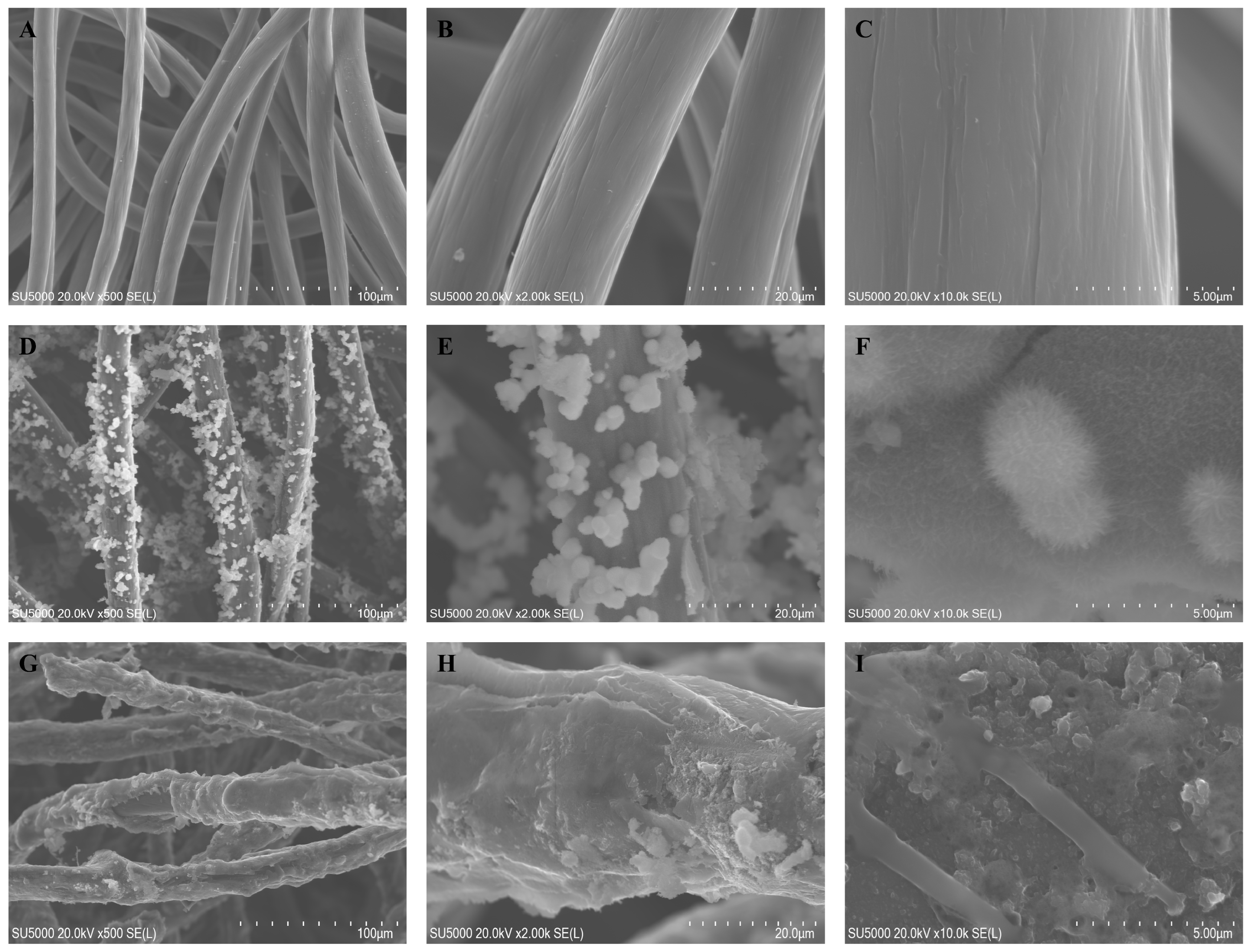
The prepared electrodes were subjected to scanning electron microscope (SEM) testing for the morphological characterization of the electrode fiber surface. Figure 2A–I show the surface microstructure of CF, CF/NiO, and CF/NiO/PANI electrodes at magnifications of 500×, 2000×, and 10,000×. Figure 2A–C clearly present the typical structure and smooth surface of the carbon fiber material of CF. By performing acid pickling and water washing treatments on the purchased CF substrate, inorganic impurities and ash on the raw material were removed, improving both the electrical conductivity and the surface characteristics of CF. This makes its surface smoother, which is conducive to the combination with subsequent composite materials. Figure 2D shows the surface microstructure of the CF/NiO electrode fiber. It can be clearly seen that the prepared NiO is uniformly and tightly loaded onto the pretreated CF fiber. The prepared NiO exhibits a dandelion-like flocculent morphology (Figure 2F), and its inherent three-dimensional structure significantly increases the specific surface area of the CF fiber. This can provide more active sites for microbial attachment and release more electrons to achieve a higher current density. Figure 2G shows that after the successful loading of PANI, the carbon fiber becomes noticeably thicker and effectively encapsulates the fiber surface and the NiO metal surface, forming a dense coral-like structure (Figure 2I). Due to the loading of PANI, the specific surface area has been further increased, and the good biocompatibility of the polymer PANI can promote the formation of a tight biofilm of microorganisms on the surface of the electrode fibers, effectively reducing the limitation of low output power density caused by the limited efficiency of the transmembrane and extracellular electron transfer processes [26]. A good biofilm can increase the current generation efficiency, enhance stability, and improve the reaction rate in the degradation of organic substances and the electron transfer process, thereby enhancing the overall energy conversion efficiency. By designing a composite material of CF, NiO, and PANI, and combining the advantages of each material, the output power of MFCs can be increased. This enables MFCs to have the functions of simultaneous power generation and energy storage, providing an effective approach for the further development of MFC applications.
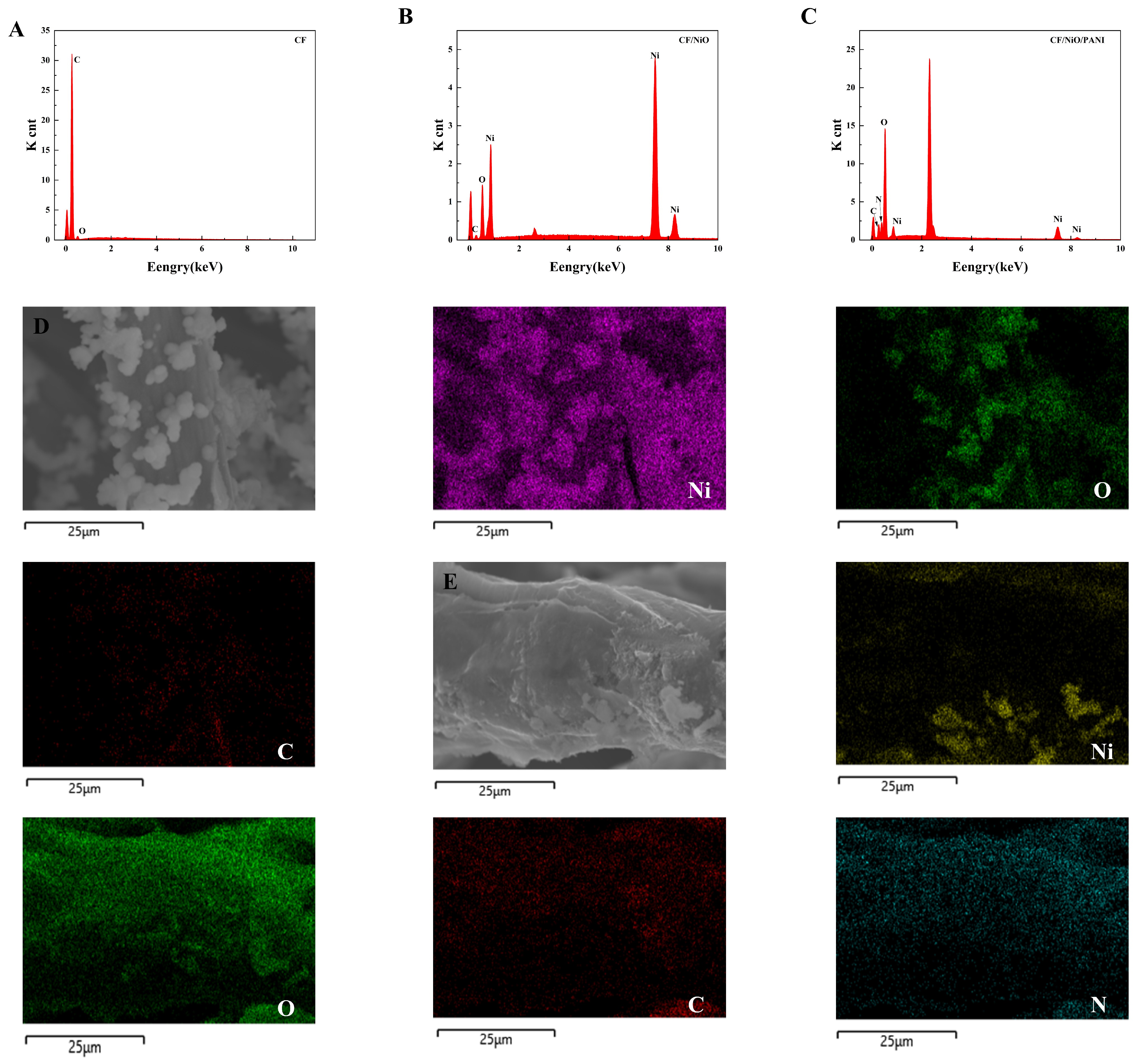
The energy dispersive spectroscopy (EDS) image in Figure 3 shows that the CF electrode after pretreatment is mainly composed of carbon (C) and oxygen (O), with no recognizable impurities (Figure 3A). The EDS of the CF/NiO electrode, shown in Figure 3B, indicates that it is primarily composed of carbon (C), oxygen (O), and nickel (Ni), with no recognizable impurities. Additionally, to provide quantitative and spatial distribution information of the elements in the carbon fibers of the CF/NiO electrode, an elemental distribution map was generated (Figure 3D). The EDS spectrum confirmed the presence of Ni, O, and C, with Ni having an atomic percentage of 55%. The EDS image in Figure 3C shows that the CF/NiO/PANI electrode fibers are mainly composed of nickel (Ni), oxygen (O), carbon (C), and nitrogen (N). Moreover, the percentage of nitrogen atoms in the CF/NiO/PANI anode reached 19.27%, and this observation indicates that the polymer (PANI) is effectively loaded onto the metal oxide (NiO). The spatial distribution information of each element is shown in Figure 3E. These elements are uniformly distributed over the entire surface of the CF/NiO/PANI electrode fibers. The uniform distribution of these elements observed in the mapping image verifies that NiO and PANI are successfully integrated onto the carbon substrate fibers. After the low-temperature polymerization process, the polyaniline molecules are interconnected on the surface of CF/NiO through hydrogen bonds, forming a tight and uniform coating. This modification can enhance the intercalation of ions and promote the diffusion of ions or electrons to the boundaries within the electrochemical cell. In addition, the composite structure of CF, NiO, and PANI provides a large effective surface area and high conductivity, ultimately improving the overall performance of the anode. This composite effect promotes sufficient contact between the reactants and facilitates the transfer of electrons and ions.
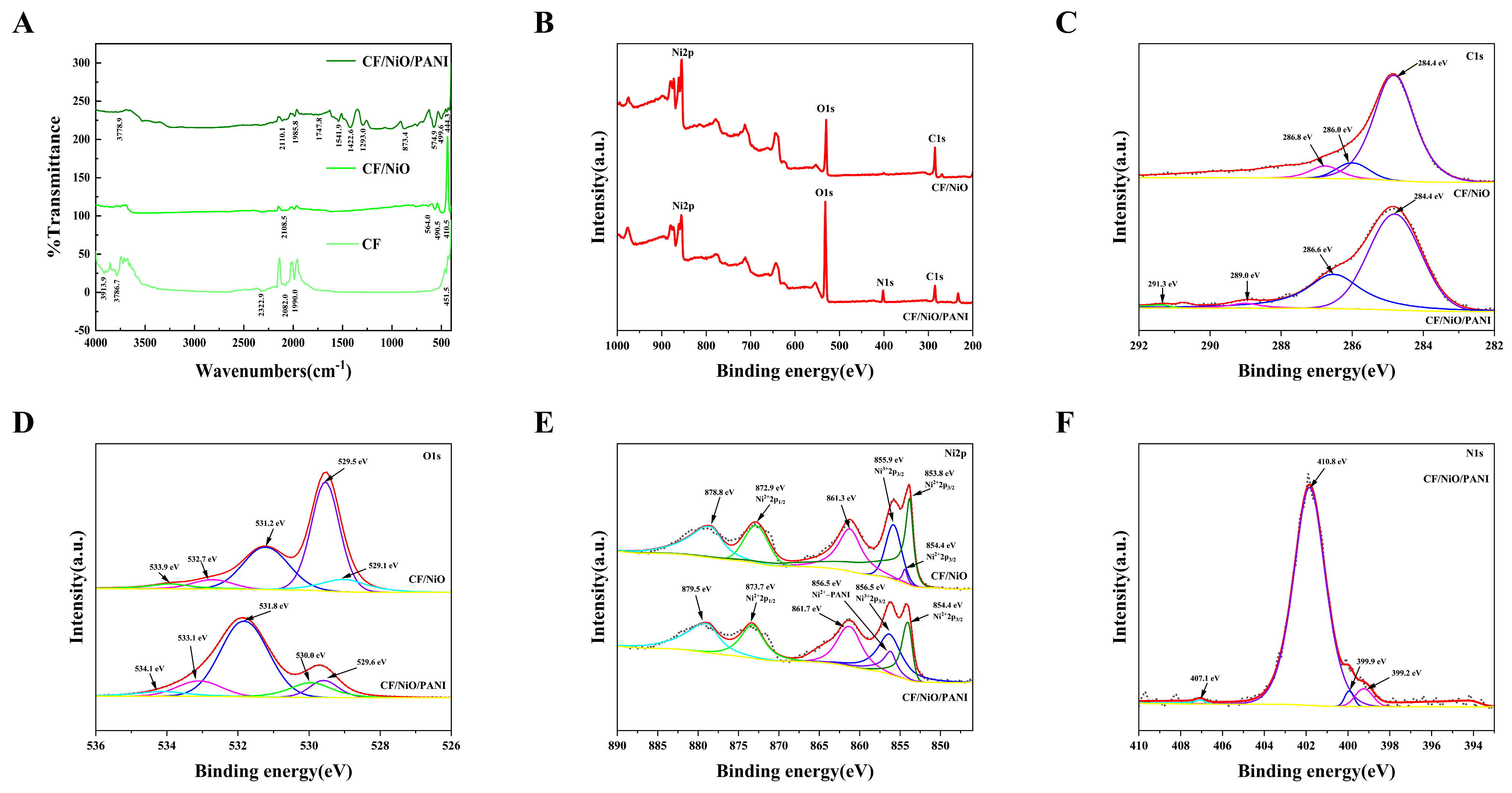
The FTIR spectra of the prepared electrode materials are shown in Figure 4A. As shown in Figure 4A, the CF/NiO composite exhibits characteristic Ni-O vibration peaks at 410.5 cm−1 (symmetric stretching), 490.5 cm−1 (asymmetric stretching), and 564.0 cm−1 (possibly related to surface hydroxyl groups or lattice defects), confirming the successful synthesis of NiO. Additionally, a peak at 1614.5 cm−1, attributed to the H-O-H bending vibration of adsorbed water, is observed due to the porous CF structure prone to adsorbing moisture. For the CF/NiO/PANI composite, the Ni-O peaks shift to higher wavenumbers (444.3, 499.6, and 574.9 cm−1; blue-shifted peaks), suggesting coordination between PANI functional groups (-NH- and -N=) and Ni2+, which redistributes the electron density and strengthens the Ni-O bonds. The reduced intensity of the C-N stretching peak at 1293.0 cm−1 could be attributed to PANI doping state variations or NiO-induced structural interference [27]. Peaks at 1541.9 cm−1 (C=C vibration in PANI quinoid rings) and 1747.8 cm−1 (oxidized C=O groups) further validate PANI incorporation. A weak peak at 3778.9 cm−1, assigned to free O-H stretching (e.g., adsorbed water or surface -OH), shows a blue-shifted position compared to the typical hydrogen-bonded O-H region (3200–3600 cm−1), likely due to steric hindrance from PANI suppressing hydrogen bond formation. These results confirm the successful loading of PANI and its chemical interaction with NiO/CF.
The surface chemical composition and interfacial interactions of carbon felt/nickel oxide (CF/NiO) and its polyaniline composite (CF/NiO/PANI) were comparatively analyzed using X-ray photoelectron spectroscopy (XPS), revealing key differences in chemical state distributions and their implications for electrode performance (in Figure 4B–F). For CF/NiO, the C 1s spectrum exhibits three characteristic peaks at 284.8 eV (C-C/C-H bonds of the carbon fiber substrate), 286.0 eV (C-O/C-N bonds from surface oxidation or residual CTAB), and 286.8 eV (C=O/O-C=O groups from deep oxidation), indicating a gradient oxidized surface formed during pretreatment and annealing. The O 1s spectrum shows dominant lattice oxygen of NiO (529.1–529.5 eV) and minor oxygen-containing groups (531.2–533.9 eV, attributed to hydroxyl, carboxyl, and adsorbed water). The Ni 2p spectrum confirms the NiO phase (Ni2+main peak at 854.4 eV) with a trace of surface Ni3+ (855.9 eV), likely from incomplete reduction during annealing. In contrast, for CF/NiO/PANI, the C 1s spectrum reveals additional peaks at 286.6 eV (C-N bonds in PANI backbone) and 291.3 eV (N-C=O from amide groups), while the O 1s spectrum shows a new peak at 534.1 eV (oxygenated species related to PANI). The N 1s spectrum further validates PANI coating through peaks at 399.2 eV (imine -N=), 399.9 eV (amine -NH-), and 401.8 eV (protonated -NH+- or Ni-PANI coordination bonds). Notably, the Ni 2p spectrum of CF/NiO/PANI exhibits a shifted peak at 856.7 eV, assigned to Ni2+ coordinated with PANI nitrogen (-N→Ni), alongside an enhanced Ni3+ signal at 856.5 eV, attributed to ammonium persulfate-induced oxidation during PANI polymerization. However, the CF/NiO electrode relies on NiO lattice oxygen and surface oxygen functional groups for redox activity, yet its performance is limited by the low conductivity of carbon fibers and instability of surface groups. In contrast, CF/NiO/PANI achieves multifunctional enhancements: (1) the conductive PANI network (-NH+- doping) improves charge transfer and capacitance; and (2) Ni-PANI coordination (856.7 eV) and Ni3+/Ni2+ redox pairs (854.4–856.5 eV) synergistically enhance interfacial charge transfer kinetics. Additionally, the hygroscopic nature of PANI likely contributes to the enhanced hydroxyl adsorption peak at 531.8 eV (O 1s), potentially facilitating ion diffusion at the electrode/electrolyte interface. The above results demonstrate that CF/NiO/PANI exhibits higher specific capacity, rate performance, and stability through chemical bonding and multi-component synergy, providing a basis for high-performance electrode designs aimed at enhancing power and energy storage in microbial fuel cells.
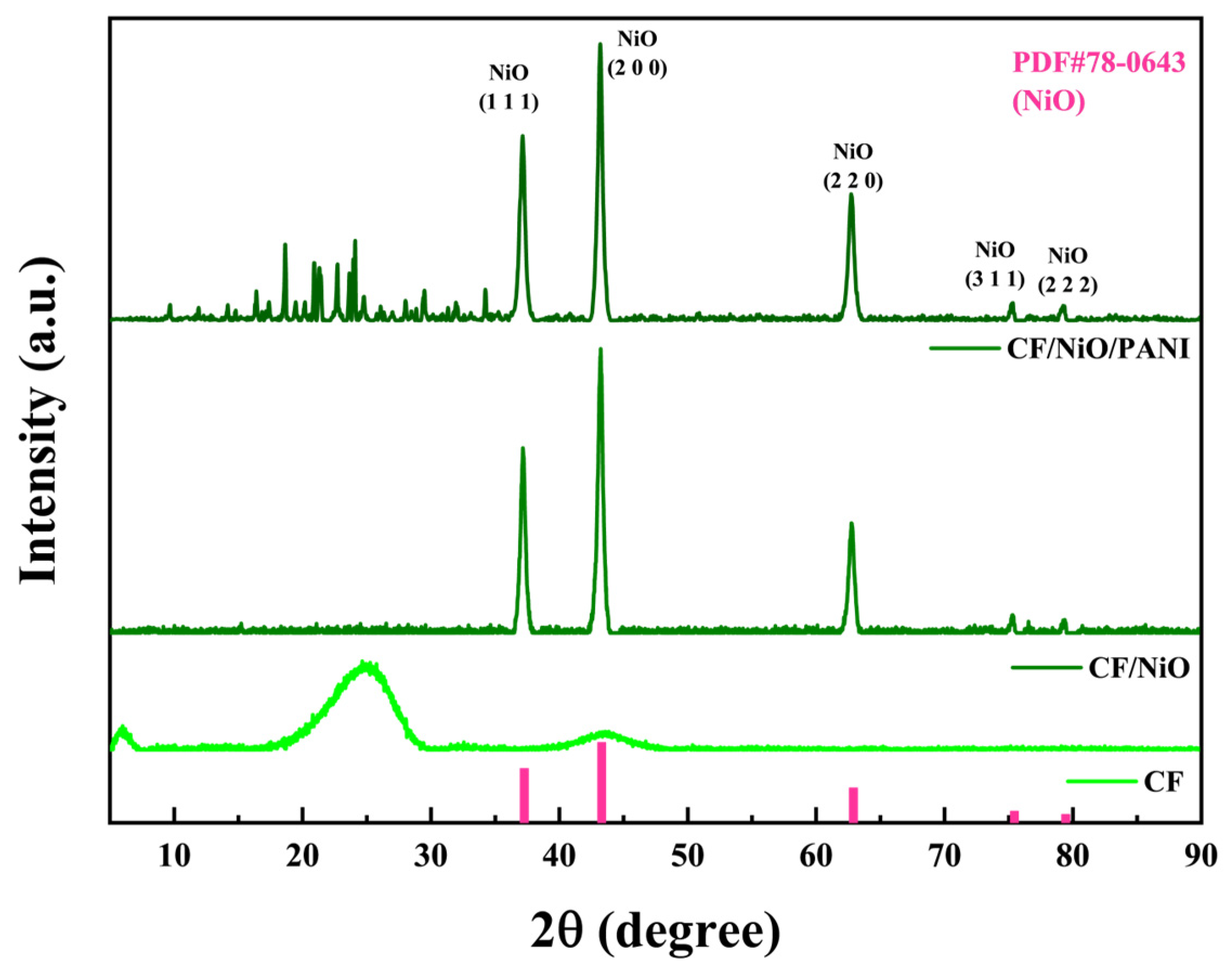
The crystal phase and structure of the experimentally prepared composite materials were characterized using X-ray diffraction (XRD). As shown in Figure 5, the diffraction peaks of the composite material CF/NiO at 2θ = 37.2°, 43.2°, 62.8°, 75.3°, and 79.4° correspond to the (111), (200), (220), (311), and (222) planes of face-centered cubic NiO (PDF#78-0643). This confirms the successful preparation and loading of NiO, and no significant impurity peaks are observed, indicating the high purity of the prepared material. For CF/NiO/PANI, the NiO peaks (37.1°, 43.2°, 62.8°, 75.3°, 79.2°) remained prominent, demonstrating that PANI deposition does not alter the crystallinity of NiO. Notably, weak diffraction peaks were observed between 10° and 30° in CF/NiO/PANI, which were absent in CF/NiO. These features were attributed to the partial ordering of PANI chains induced by interfacial interactions with NiO, as supported by XPS analysis (e.g., in Figure 4F, N 1s peak at 401.8 eV for Ni2⁺-N coordination). Such interactions were found to promote local alignment of PANI chains, generating weak diffraction signals typically associated with π-π stacking (15°–25°). However, the broad and low-intensity features suggested that PANI remained predominantly amorphous, consistent with its low crystallinity in composite systems. These diffraction peaks appear to result from the overlap of NiO peaks and PANI peaks. The peak intensities indicated that the surface-deposited PANI did not significantly affect the crystallization characteristics of NiO [28,29,30]. It is noteworthy that the loading of polyaniline preserved the crystalline structure and pseudocapacitive properties of NiO while enhancing electrode biocompatibility. Strong interfacial interactions were formed among polyaniline, CF, and NiO, leading to significantly improved MFC output power. This configuration achieved dual functionality for simultaneous power generation and energy storage, ultimately enhancing the performance of the MFCs.

3.2. Output Characteristics of MFCs

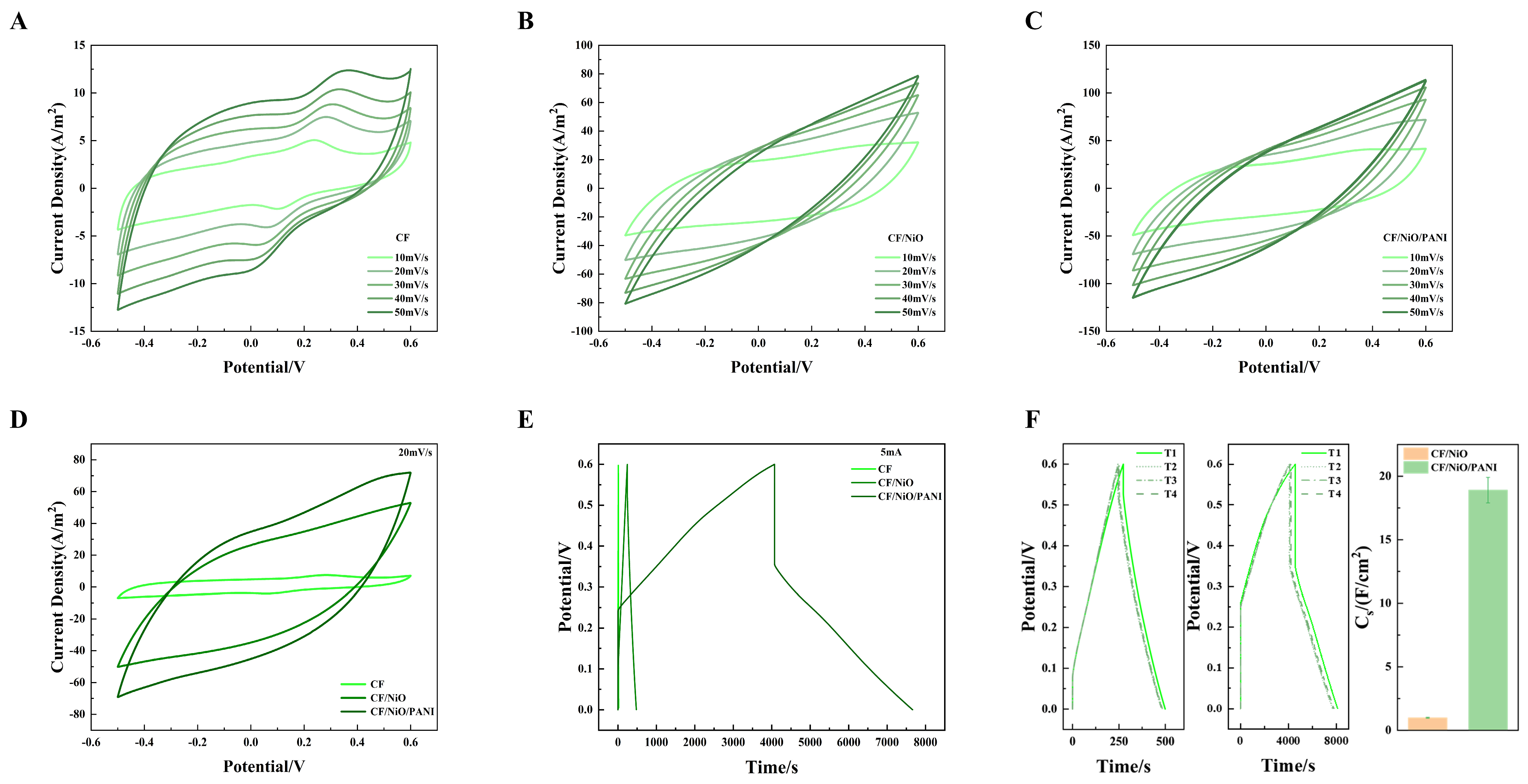
The cyclic voltammetry (CV) analysis was performed on the prepared CF, CF/NiO, and CF/NiO/PANI electrode samples, with the corresponding data presented in Figure 6A–D. As shown in Figure 6A–C, when the scan rate was increased from 10 mV/s to 50 mV/s, the CV curve contour shapes of CF, CF/NiO, and CF/NiO/PANI maintained unchanged shapes with consistent symmetry and stability. It is worth noting that CF/NiO/PANI exhibited a symmetrical rectangular CV curve with a broad oxidation peak, confirming the formation of an electric double layer (EDL) on its surface. The enhancement of capacitance originates from the pseudocapacitive contributions of NiO, the unique pore structure providing more active sites for ions to enter the electrode surface, and the unique electrochemical properties and doping mechanism of PANI. The PANI-NiO composite demonstrated significantly improved capacitive energy storage and structural stability compared to individual components. This hybrid structure reduces energy dissipation through optimized charge transfer pathways, thereby extending the electrode lifespan. For direct comparison, CV data acquired at 20 mV/s within the −0.6 V to 0.5 V potential window were analyzed. As shown in Figure 6D, both CF/NiO and CF/NiO/PANI exhibited CV curves with substantially larger enclosed areas and improved symmetry compared to pure CF. The larger enclosed area and good CV curve indicate that the electrode has a large specific capacitance and good stability. This observation suggests that the charge transfer resistance in the CF/NiO electrode is low and there is sufficient active surface area for electron transfer. Despite the absence of distinct redox peaks, the quasi-rectangular CV profile of CF/NiO confirms excellent capacitive behavior from NiO modification. It is worth noting that the capacitance of the CF/NiO/PANI anode is significantly higher than that of the CF/NiO and blank CF anodes. This increase in capacitance can be attributed to the modification by pseudocapacitive materials such as metal oxides and polymers. Although no redox peaks were observed, symmetrical oxidation and reduction processes occurred at almost the same rate. This finding indicates that the charge–discharge process of the CF/NiO/PANI anode is relatively reversible. The larger pore size on the anode surface facilitates the rapid transfer of ions in the electrolyte (with low diffusion resistance) both inside and outside the electrode. Furthermore, minimized contact resistance ensures efficient charge transfer, accelerating redox kinetics and thereby boosting pseudocapacitive performance.
Figure 6E shows the CP curves obtained by potentiostatic analysis of blank CF, CF/NiO, and CF/NiO/PANI anodes. It can be clearly seen from Figure 6E that the discharge time (3592s) of the CF/NiO/PANI electrode is significantly longer than that of the blank CF electrode and the CF/NiO electrode (479s). The significant increase in the charging/discharging time indicates that a more excellent specific capacitance performance is achieved after modification with the composite of NiO and PANI. The specific capacitance ( C s ) is calculated using Formula (2). The specific capacitance ( C s ) was calculated using the following equation:
C s = 2 i A V   d t V 2 V i V f
where C s indicates the specific capacitance (mF/cm2) of the MFC device; V   d t denotes the curve integral area (V·s); i A refers to the current density (A/cm2) of the fabricated electrode; and V i and V f represent the initial potential (V) and the terminal voltage (V) of the external resistor in the MFC device, respectively.
The C s value of the CF/NiO electrode is 0.98 ± 0.04 F/cm2. This indicates that, at the same current density (1.25 mA/cm2), its capacitance performance is 24.5 times higher than that of the blank CF electrode (0.04 F/cm2). The C s value of the CF/NiO/PANI electrode is 18.91 F/cm2. At the same current density, its capacitance performance is 472.8 times higher than that of the blank CF electrode (0.04 F/cm2) and 19.3 times higher than that of the CF/NiO electrode (0.98 ± 0.04 F/cm2). When the current density is 1.25 mA/cm2, the chronopotentiometry (CP) curve of CF/NiO resembles the shape of an isosceles triangle (Figure 6E). This observation is highly consistent with the typical high capacitance performance of a double-layer capacitor. Meanwhile, the repetitive data from multiple independent experiments (Figure 6F) indicate the stability of the electrode and the feasibility of the experimental method. In addition, the combination of NiO and PANI is conducive to promoting a good ion diffusion rate, enabling the electrode to have an excellent energy storage capacity as well as superior cycling performance. It is precisely due to the enhanced charge storage performance of NiO and the efficient reversible redox reaction pseudocapacitance characteristics of PANI, along with its good conductivity and biocompatibility, that the CF/NiO/PANI electrode is expected to enhance the power generation capacity and charge storage performance of MFCs.
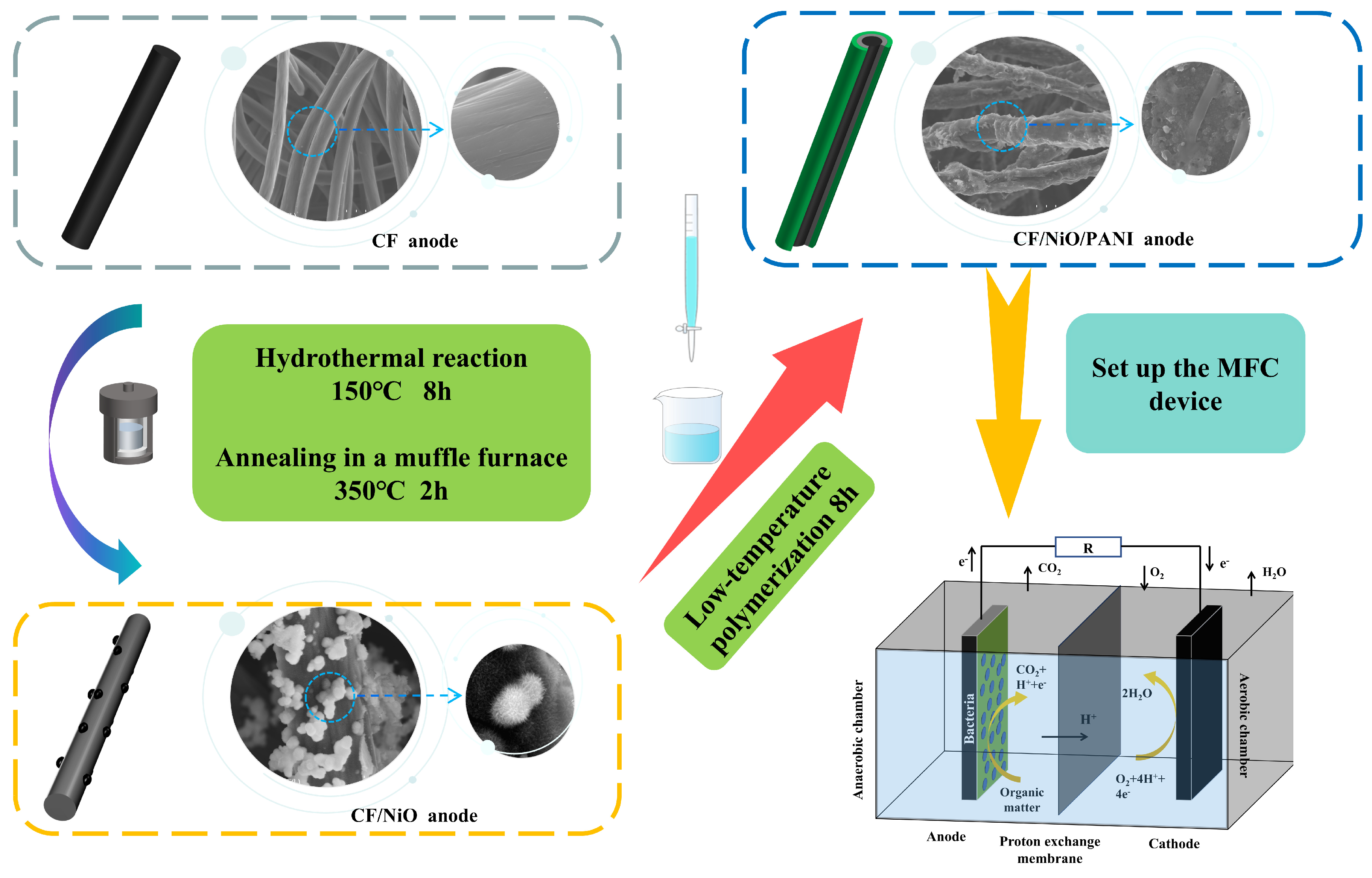
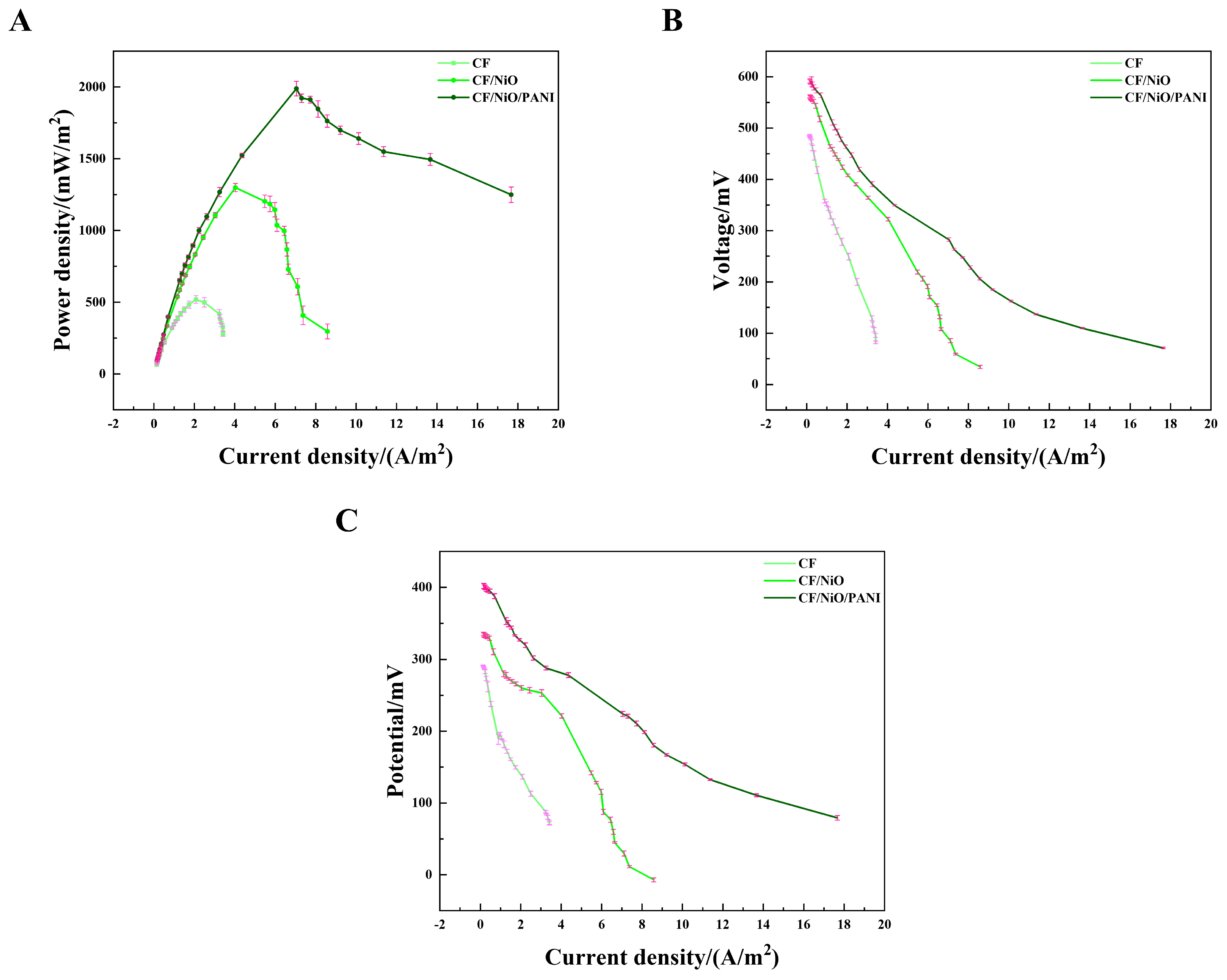
To evaluate the power output, the MFC device was constructed in a two-chamber container (Figure S1). Initially, the output voltage of the MFC increased continuously with time. Within approximately 3 days, it reached a relatively stable state, indicating the successful construction of the MFC. Once the output voltage stabilized, the 8000 Ω resistor used during the initial phase was disconnected, and an external sliding rheostat was connected between the cathode and the anode. The load resistance values in the circuit were varied to obtain the corresponding voltage values. The power density curve, current–voltage (I–V) curve, and anode polarization curve were obtained through calculation. The power density curve (Figure 7A) shows that the maximum power densities of the three electrodes have significant differences. The maximum power density of the blank CF electrode was measured to be 518.29 ± 27.07 mW/m2 by averaging multiple measurements. However, the average maximum power density of the CF/NiO/PANI electrode reached 1988.31 ± 50.96 mW/m2, which is much higher than that of the CF/NiO electrode (1298.84 ± 28.32 mW/m2) and the blank CF (518.29 ± 27.07 mW/m2). The maximum power density achieved by the CF/NiO/PANI electrode is significantly higher than that of other electrode materials previously reported (Table 1). Additionally, Figure 7B shows that the open circuit voltages of the CF/NiO and CF/NiO/PANI electrodes are similar at approximately 0.6 V, which is consistent with the maximum voltage output of similar MFCs. It was noted that the CF/NiO/PANI electrode displayed the maximum average current output of 17.67 ± 0.38 A/m2, which was significantly higher than that of the blank CF (3.42 ± 0.11 A/m2) and CF/NiO (8.58 ± 0.76 A/m2). It was proven that a large number of microorganisms effectively transformed organic matter and released electrons, achieving relatively high current density and stability. Moreover, the anode polarization curve (Figure 7C) provided further evidence supporting the excellent electrochemical performance of the composite bioanode. In Figure 7C, the polarization curve of the CF/NiO/PANI anode was the most gradual, indicating high electrochemical reaction activity and efficient electron transfer between the anode and microorganisms, while the polarization curve of the blank CF anode showed the most drastic change, suggesting limited reaction activity.
Among these three electrodes, the CF/NiO/PANI capacitive bioanode exhibits greater power density and superior polarization performance. The innovative multilayer structure significantly enhances the availability of active sites on the electrode and shortens the ion diffusion path, thereby forming a more direct conduction path [31,32,33,34]. The incorporation of NiO enhances both the power output performance and pseudocapacitance of the electrode, while the increased specific surface area promotes higher loading of PANI. The addition of PANI facilitates charge transfer due to its excellent biocompatibility and promotes the growth of electrogenic bacteria, which further enhances the energy storage performance of the electrode. Therefore, the increase in current density can be attributed to either a higher bacterial load in the anode biofilm or more efficient charge transfer with reduced charge loss due to the enhanced charge transfer rate. Additionally, the synergistic effect of incorporating NiO and PANI, along with the increased specific surface area, improved electrochemical properties, better conductivity, and enhanced quasi-Faraday effect, collectively contribute to the MFC exhibiting higher output power and superior polarization performance.
Table 1. The power densities of MFCs modified with polymers and metal oxides on the anode documented in the literature.
ReferencesAnodePower Density
1This studyCF/NiO1298 ± 28 mW/m2
2This studyCF/NiO/PANI1988 ± 51 mW/m2
3Park et al. [15]CP/CNT/Fe3O4830 mW/m2
4Wang et al. [19]CF/MnO2872.0 mW/m2
5Wang et al. [19]CF/MnO2/PANI/MnO21124.8 mW/m2
6Kumar et al. [35]NiO/RGO71.1 mW/m2
7Peng et al. [36]AC/SSM664 ± 17 mW/m2
8Peng et al. [36]AC/Fe3O4/SSM809 ± 5 mW/m2
9Mishra et al. [37]CC/MWCNT-MnO2/PPy1125.4 mW/m2
10Mehdinia et al. [38]MWCNT/SnO2/GC1421 mW/m2
11Feng et al. [39]CF/AQDS/PPy1300 mW/m2
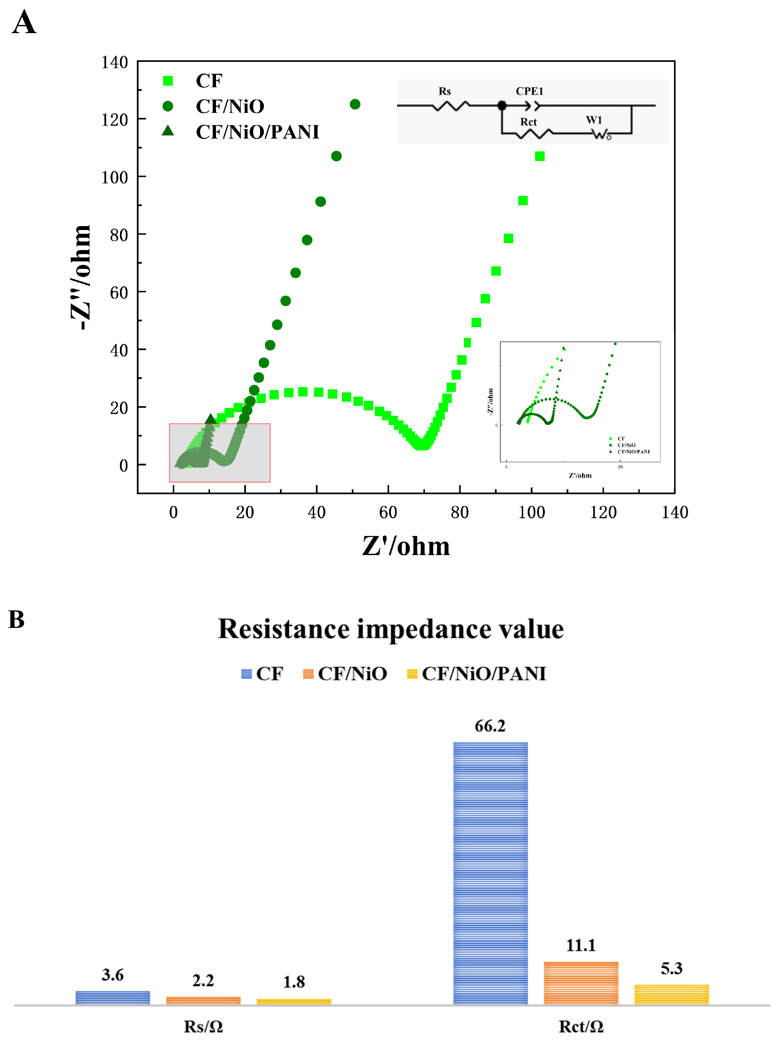
In order to study the reasons for the performance improvement of MFCs and evaluate the charge transfer efficiency through the electrolyte/electrode interface, electrochemical impedance spectroscopy (EIS) tests were conducted in the frequency range of 0.01 Hz to 100 kHz. The semicircle at high frequencies corresponds to part of the electron transfer process, while the linear portion at low frequencies indicates good capacitive behavior due to rapid electron transfer. The internal circuit diagram represents the equivalent fitting circuit used to analyze the corresponding EIS data. This circuit includes electrolyte resistance (Rs), double-layer capacitance (Cdl), charge transfer resistance (Rct), and the Warburg element (Rw). Rs encompasses solution resistance, electrode internal resistance, contact resistance, and electrolyte ion resistance within the system [40]. It can be directly read from Figure 8B that the Rs value of the CF/NiO/PANI electrode is 1.8 Ω, which is significantly lower than that of the blank CF electrode (3.6 Ω) and the CF/NiO electrode (2.2 Ω). This suggests that the conductivity between the electrolyte solution and the prepared composite electrode material CF/NiO/PANI has been enhanced. These results indicate that the CF/NiO/PANI electrode structure facilitates the rapid migration of electrolyte ions and the efficient transfer of electrons into the material. The Rct values of the CF electrode, the CF/NiO electrode, and the CF/NiO/PANI electrode are 66.2 Ω, 11.1 Ω, and 5.3 Ω, respectively. Both the Rs and Rct values of the CF/NiO/PANI electrode are much lower than those of the blank CF electrode, indicating a significant improvement in the rate of electron transfer from bacteria to the electrode. This improvement is mainly attributed to the increase in the anode’s specific surface area, the nanostructured network formed by polyaniline that promotes the electron conduction path, and NiO that enhances the ability of direct electrochemical interaction between bacterial cells and the electrode, which jointly enhance the charge transfer efficiency of the entire system. However, in the low-frequency range of Figure 8A, the slope of the linear part is related to the magnitude of the Warburg resistance (Rw), and the magnitude of Rw is attributed to the diffusion of electrolyte ions within the electrode pores. Moreover, a lower slope of the straight line indicates a higher Rw. As observed from the figure, in the low-frequency range, the slope of the straight line decreases successively from the CF/NiO/PANI electrode to the CF/NiO electrode, and then to the blank CF electrode. Therefore, the Warburg resistance (Rw) increases in this order, and the ion diffusion rate also gradually slows down. Among these three electrodes, the electrochemical performance of the CF/NiO/PANI electrode is the best. The above results indicate that the enhanced conductivity of polyaniline and the improved catalytic performance of nickel oxide contribute to the increased electrochemical activity and reaction kinetics of the electrode. The structural optimization of the composite material increases the current transmission capacity and contact area while maintaining good mechanical strength and stability, thereby effectively reducing the overall impedance of the electrode.

3.3. Storage Capacity of MFCs

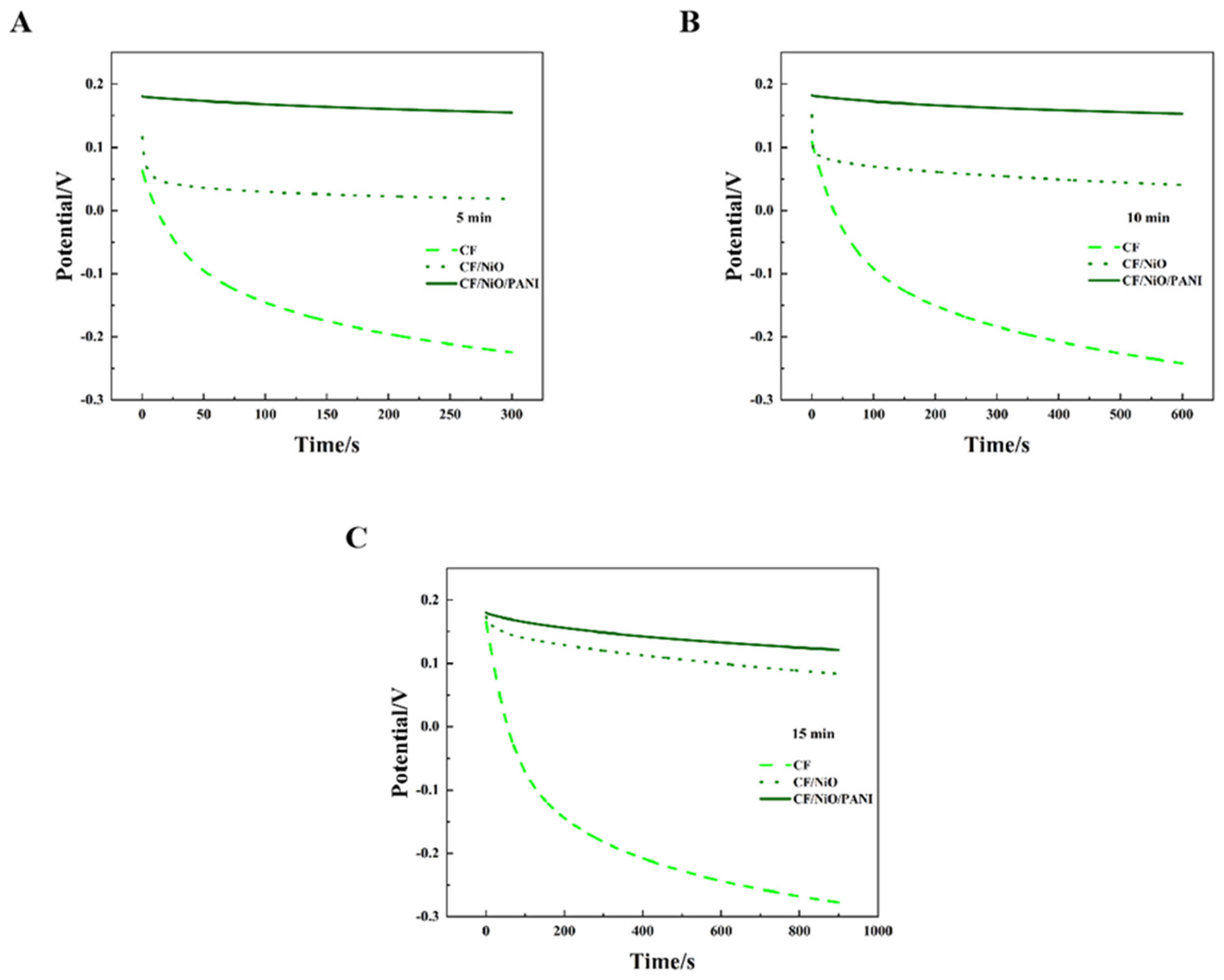
Figure 9A–C show the open circuit potential–time profiles of MFCs with electrodes CF, CF/NiO, and CF/NiO/PANI when an external 200 Ω resistor is connected during charging periods of 5 min, 10 min, and 15 min, respectively. It is worth noting that the potentials of the three anodes all exhibited a similar downward trend in the open circuit potential–time curves at 5 min, 10 min, and 15 min. However, distinct differences in decay rates were observed among the anodes in each dataset. Among them, the blank CF anode has the most pronounced decline, followed by the CF/NiO anode, while the CF/NiO/PANI anode exhibits the weakest downward trend. In Figure 9C, the blank CF anode potential plummeted from 0.166 V to −0.278 V. In contrast, the potential change of the CF/NiO anode was relatively slow, dropping from an initial potential of 0.174 V to 0.083 V over a period of 15 min. Compared with the blank CF anode, this electrode exhibited a higher initial potential. This behavior suggests that NiO’s high electrochemical activity enhanced oxidation kinetics, while its uniform coating (Figure 8B) reduced charge transfer resistance. These combined effects enabled the CF/NiO anode to maintain a higher initial potential with suppressed current loss, thereby prolonging potential retention. Additionally and most significantly, the initial potential of the CF/NiO/PANI anode dropped from 0.180 V to 0.121 V after 15 min. This 0.059 V decay was significantly smaller than the 0.444 V and 0.091 V losses observed for the blank CF and CF/NiO anodes, respectively. The incorporation of NiO provided a larger specific surface area for CF fibers, promoting the loading of PANI. Meanwhile, the pseudocapacitance characteristics of NiO and PANI, as pseudocapacitive materials, facilitated rapid N-type or P-type doping and dedoping redox reactions, ultimately leading to the enhancement of Faradaic capacitance. Therefore, the CF/NiO/PANI composite electrode stored more charges compared to the CF/NiO electrode and the blank CF electrode, achieved a higher initial potential, and exhibit better electrical conductivity and environmental stability, thereby enhancing the energy storage capacity of MFCs and slowing down the decrease in anode potential.
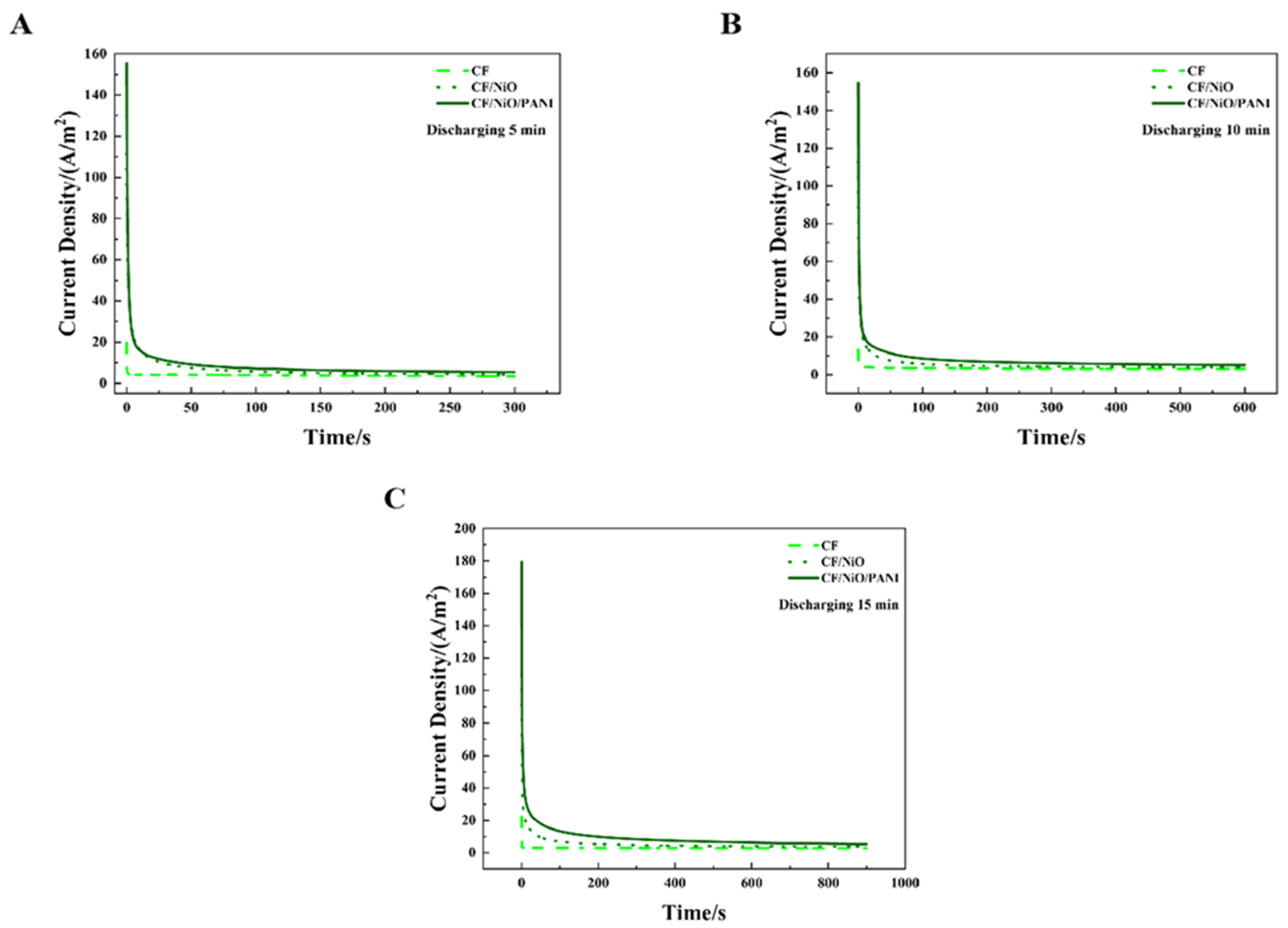
Figure 10 shows the MFC discharge curves of the three electrodes under an external resistor (200 Ω) condition at charge–discharge cycle periods of 5 min, 10 min, and 15 min. It can be seen from Figure 10A–C that the discharge curves of these three electrodes all exhibit a peak current density, after which the current density decreases over time and eventually reaches a relatively stable state. Based on the existing data, Table 2 can be obtained through calculation and visually presents the peak current density (ih), steady-state current density (is), charge storage capacity (Qs), and total charge quantity (Qt) of the three electrodes across different charge–discharge cycle periods. It can be seen from Table 2 that in the 15 min charge–discharge cycle, the peak current density (ih) of the MFC with the CF/NiO/PANI electrode reached 179.40 A/m2, which was much higher than that of the MFC with the blank CF electrode (20.00 A/m2) and the MFC with the CF/NiO electrode (110.43 A/m2). Meanwhile, the steady-state current density (is) of the MFC with the CF/NiO/PANI electrode reached 5.41 A/m2, which was much higher than that of the MFC with the blank CF electrode (3.60 A/m2) and the MFC with the CF/NiO electrode (3.86 A/m2). It is worth noting that the total charge (Qt) and stored charge (Qs) of the CF/NiO/PANI electrode reached 8175.89 C/m2 and 3304.64 C/m2, respectively, which were significantly higher than those of the blank CF electrode (Qt = 4860.50 C/m2, Qs = 1386.50 C/m2) and the CF/NiO electrode (Qt = 3552.50 C/m2, Qs = 314.75 C/m2). The total charge (Qt) and stored charge (Qs) of the CF/NiO/PANI electrode were 1.74 times and 2.38 times those of the blank CF electrode, and 2.30 times and 10.44 times those of the CF/NiO electrode, respectively. Similarly, the results of the charge–discharge tests conducted at 5 min and 10 min were consistent with the trend observed in the 15 min charge–discharge tests.
The chronoamperometry test (CA) results show that among these three electrodes, the MFC equipped with the CF/NiO/PANI electrode not only has the highest peak current and steady-state current but also exhibits the largest total charge and stored charge, reaching 2.30 times and 10.50 times that of the blank CF electrode, respectively. This significant enhancement indicated that NiO modification (CF/NiO) endowed the electrode with excellent energy storage capability and high power output. Uniform NiO deposition on carbon fibers (Figure 2D) increased the specific surface area, facilitating microbial attachment/growth/colonization, providing abundant active sites, and enhancing electrochemical activity. As an efficient catalyst, NiO promoted electrochemical reactions, accelerated kinetics, boosted current density, and enabled higher current output at identical potentials. Additionally, the introduction of NiO improved the double-layer capacitance characteristics of the electrode and enhanced the capacitance performance, resulting in a higher total charge and charge storage capacity under good electrical conductivity. Notably, the increased surface area after loading NiO allows carbon fibers to load more PANI. PANI, as a conductive polymer, significantly improves the conductivity of the electrode and enhances the charge transfer efficiency when combined with CF and NiO. Both PANI and nickel oxide exhibit good electrochemical catalytic effects, accelerated the electrochemical reaction kinetics, thereby accelerated current density. Furthermore, their combination can generate a synergistic interaction between them, providing more active sites for the electrochemical reactions in microbial fuel cells. The expanded surface area enhanced reactant accessibility to active sites, while the composite EDL effect improved both reaction rates and capacitive energy storage. Simultaneously, the optimized surface properties of the composite promoted microbial adhesion, strengthening microbe–electrode interactions and boosting energy conversion efficiency. Simultaneously, the optimized surface properties of the composite promoted microbial adhesion, strengthening microbe–electrode interactions and boosting energy conversion efficiency. During power shortages, the MFC stored microbially generated energy within its capacitive anode. When power output is required, the MFC can release a higher current, including both the newly generated current and the previously stored current, thereby increasing the overall output power of the device.

3.4. Analysis of Anode Biodiversity and Microbial Community Structure

The basic principle of MFCs is to convert the chemical energy in the substrate into electrical energy using the metabolic processes of microorganisms. The selection of electroactive bacteria has a decisive influence on the performance of MFCs, as different types of microorganisms can significantly alter the current density, energy efficiency, and voltage output. In addition, microorganisms can efficiently decompose complex organic substances into simple and available compounds through the action of metabolic enzymes, thereby maximizing the available energy of the battery. Therefore, microorganisms play a core role in MFCs and directly determine the performance, efficiency, and operational stability of the battery. In this study, we conducted high-throughput sequencing analysis on the surfaces of blank carbon fiber (CF) anodes and modified anodes to explore the microbial community structure and the distribution of electrogenic bacteria. This study aims to deeply explore the key factors that contribute to improving the power generation and energy storage performance of MFCs.
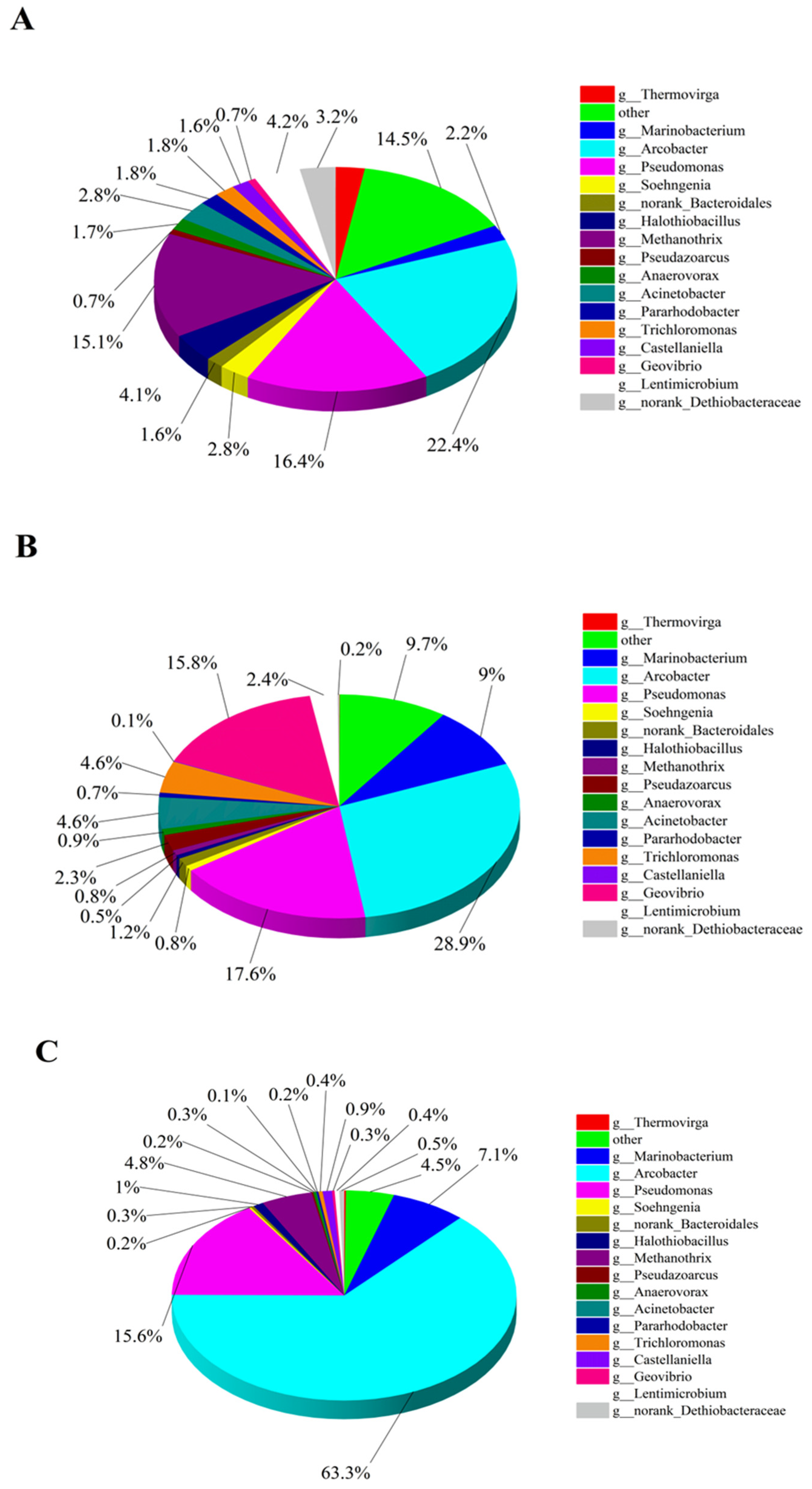
In this high-throughput test, the blank CF anode was used as the control group and labeled as A1, while the CF/NiO anode and the CF/NiO/PANI anode in the experimental groups were labeled as A2 and A3, respectively. Figure 11A–C show the pie charts of the microbial community composition structure on the anode surface at the genus level for the three anodes. It can be seen from Figure 11A that the microbial community on the surface of the blank CF anode was primarily composed of Arcobacter (22.3%), Pseudomonas (16.3%), Methanothrix (15.1%), Lentimicrobium (4.1%), and Acinetobacter (2.8%), among others. Among them, the main electrogenic bacteria such as Arcobacter, Pseudomonas, and Acinetobacter account for approximately 41.5%. Methanothrix is a non-electrogenic bacterium. In the MFC system, such bacteria only consume the organic matter in the anode chamber and cannot provide electrical energy for the system. It is regarded as a non-beneficial bacterium in the research on MFC electricity generation. In Figure 11B, the microbial community on the surface of the CF/NiO anode is mainly composed of Arcobacter (28.9%), Pseudomonas (17.6%), Geovibrio (15.7%), Marinobacter (9.0%), and Trichloromonas (4.6%). The proportion of the main electrogenic bacteria has reached 65.7%, which is significantly higher compared with the blank CF anode. This observation indicates that the loading of NiO provides more suitable environmental conditions for the attachment and metabolism of electrogenic bacteria. The microbial community on the surface of the CF/NiO/PANI anode was mainly composed of Arcobacter (63.3%), Pseudomonas (15.6%), Methanothrix (4.8%), and Marinobacterium (7.1%). Notably, the proportion of the main electrogenic bacteria reached 79.2%, which was significantly higher than that of the blank CF anode (41.5%), with the proportion of Arcobacter increasing from 22.3% to 63.3%. The results indicated that in the limited organic matter environment in the anode chamber, more organic matter was utilized by the electrogenic bacteria, reducing the metabolic consumption of non-beneficial bacteria, thereby increasing charge generation and enhancing electricity production. This can be attributed to the addition of NiO and PANI, which effectively increased the electrogenic bacterial community in the MFC, enhancing its overall performance by improving conductivity, promoting microbial attachment and growth, and enhancing electrochemical reactions. This finding is consistent with the measured power test results.
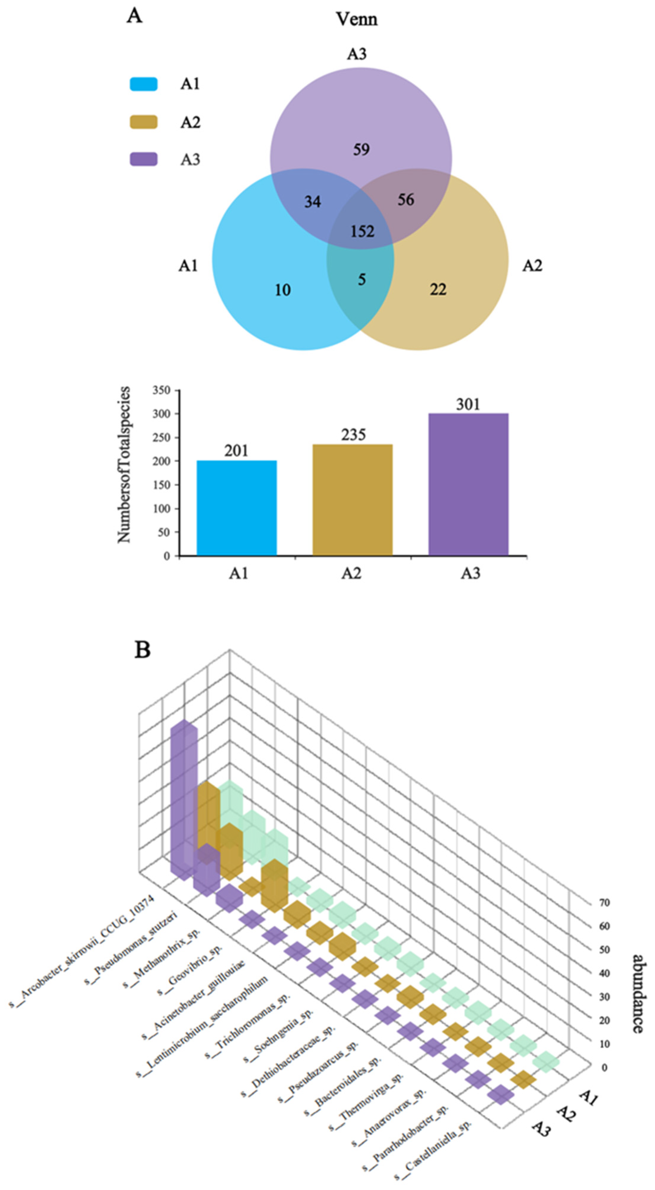
To investigate the enhanced electrochemical performance of the CF/NiO/PANI bioanode, species-level Venn analysis was performed on the microbial communities of the anode surfaces of the three electrodes. The blank CF anode served as control (A1), with CF/NiO and CF/NiO/PANI designated as A2 and A3, respectively. The Venn diagram (Figure 12A) revealed distinct microbial diversity patterns among the three anodes. The analysis identified 338 species of microorganisms across the three electrodes, with a total of 152 unique species. Notably, the microbial community of the CF/NiO/PANI anode comprised 301 species, including 59 unique species, which was higher than that of the blank CF anode (201 species, 10 unique species) and the CF/NiO anode (235 species, 22 unique species). The results demonstrate that there are significant differences in the dominant species between the multilayer capacitive biological anode modified with NiO and PANI composite material and the blank CF anode, and the data in Figure 11 also support this observation. The 3D species abundance histogram (Figure 12B) further visualizes the dominant microbial populations within the anode chamber microenvironment. The dominant species in A3 include electrogenic bacterial communities such as Arcobacter and Pseudomonas, which account for 78.9%. This percentage is higher than the total abundance of the dominant species Arcobacter, Pseudomonas, and Geovibrio in the electrogenic community of A2 (61.2%) and higher than the total abundance of the dominant species Arcobacter, Pseudomonas, Geovibrio, and Acinetobacter in the electrogenic community of A1 (42.2%). Compared with the CF anode, the CF/NiO/PANI anode shows higher total biomass, richer microbial diversity, and increased aggregation of electrogenic bacteria. These findings confirm that the CF/NiO/PANI bioanode combines exceptional biocompatibility with superior power density (1988.31 ± 50.96 mW/m2).

4. Conclusions

The primary objective of this study was to enhance the power density and charge storage capacity of microbial fuel cells (MFCs). The electrochemical, morphological, and chemical properties of the fabricated anode were characterized using SEM, EDS, FTIR, XPS, and XRD. Structural characterization revealed that a dense, coral-like 3D coating formed on the modified electrode surface, effectively enhancing its conductivity, catalytic activity, biofilm formation capacity, and specific surface area. Notably, the MFC equipped with the CF/NiO/PANI bioanode achieved a peak power density of 1988.31 ± 50.96 mW/m2, representing a 3.8-fold increase over the blank CF anode (518.29 ± 27.07 mW/m2). Furthermore, charge–discharge cycling tests demonstrated that the CF/NiO/PANI bioanode exhibited a charge storage capacity of 3304.64 C/m2, 10.5 times higher than the blank CF anode. The charge transfer resistance of the CF/NiO/PANI electrode decreased from 66.2 Ω (that of the CF electrode) to 5.3 Ω. During the 15 min open circuit potential test, the magnitude of the decrease for the CF/NiO/PANI electrode was the smallest (only 59 mV), which was significantly lower than those of the CF/NiO electrode (91 mV) and the CF electrode (444 mV). Meanwhile, regarding the microbial community composition at the genus level, the proportion of electrogenic bacteria in the CF/NiO/PANI bioanode reached 79.2%, a value higher than that of the blank CF electrode (41.5%). At the species level, the CF/NiO/PANI bioanode also exhibited higher total biomass, greater microbial diversity, and a higher aggregation of electrogenic bacteria (301 species in total, including 59 unique species). The CF/NiO/PANI-integrated MFC demonstrated superior power output, enhanced biocompatibility, and efficient dual functionality for simultaneous energy generation and storage.

Supplementary Materials

The following supporting information can be downloaded at: https://www.mdpi.com/article/10.3390/coatings15030356/s1, Figure S1. A physical illustration of a double-chamber microbial fuel cell. Figure S2. The Shanghai Chenhua CHI760E workstation is used for electrochemical testing. Table S1. The formula of the anode chamber nutrient solution.

Author Contributions

Conceptualization, Y.W.; Methodology, Z.W.; Software, Y.S.; Formal analysis, X.K.; Resources, S.M.; Data curation, Y.D.; Writing—original draft, V.P.; Supervision, D.Z.; Project administration, A.V. All authors have read and agreed to the published version of the manuscript.

Funding

The project was funded by the Provincial Foreign Expert Program for 2024 (NO. G2024050); the Opening Project of Shanxi Province Key Laboratory of Chemical Process Intensification, North University of China (NO. 2024-CPI07); and the State Key Laboratory of Microbial Technology Open Projects Fund (Project NO. M2024-19).

Data Availability Statement

The original contributions presented in this study are included in the article/Supplementary Materials. Further inquiries can be directed to the corresponding author.

Conflicts of Interest

The authors declare no conflicts of interest.

References

  1. Karthikeyan, C.; Sathishkumar, Y.; Lee, Y.S.; Kim, A.R.; Yoo, D.J.; Gnana Kumar, G. The influence of chitosan substrate and its nanometric form toward the green power generation in sediment microbial fuel Cell. J. Nanosci. Nanotechnol. 2017, 17, 558–563. [Google Scholar] [CrossRef] [PubMed]
  2. Singh, S.; Bairagi, P.K.; Verma, N. Candle soot-derived carbon nanoparticles: An inexpensive and efficient electrode for microbial fuel cells. Electrochim. Acta. 2018, 264, 119–127. [Google Scholar] [CrossRef]
  3. You, S.; Zhao, Q.; Zhang, J.; Jiang, J.; Wan, C.; Du, M.; Zhao, S. A graphite-granule membrane-less tubular air-cathode microbial fuel cell for power generation under continuously operational conditions. J. Power Sources 2007, 173, 172–177. [Google Scholar] [CrossRef]
  4. Budania, Y.; Mishra, Y.; Mishra, Y.; Jana, A.; Modi, Y.; Tyagi, Y.; Kumar, P.; Singh, S. Multi-heteroatom doped vehicle exhaust soot derived nano-onion based economical and efficient electrodes for microbial fuel cell: A waste to wealth strategy. Chem. Eng. J. 2023, 474, 145627. [Google Scholar] [CrossRef]
  5. Dessie, Y.; Tadesse, Y.; Eswaramoorthy, R.; Adimasu, Y. Biosynthesized α-MnO2-based polyaniline binary composite as efficient bioanode catalyst for high-performance microbial fuel cell. All Life 2021, 14, 541–568. [Google Scholar] [CrossRef]
  6. Simoska, O.; Cummings, D.A., Jr.; Gaffney, E.M.; Langue, C.; Primo, T.G.; Weber, C.J.; Witt, C.E.; Minteer, S.D. Enhancing the performance of microbial fuel cells via metabolic engineering of escherichia coli for phenazine production. ACS Sustain. Chem. Eng. 2023, 11, 11855–11866. [Google Scholar] [CrossRef]
  7. Subhadarshini, S.; Sravan, J.S.; Sarkar, O.; Venkata Mohan, S.; Roy, T.K.; Jana, T. Sulfonated polybenzimidazole as a PEM in a microbial fuel cell: An efficient strategy for green energy generation and wastewater cleaning. ACS Appl. Energy Mater. 2023, 6, 1422–1438. [Google Scholar] [CrossRef]
  8. Sonawane, J.M.; Yadav, A.; Ghosh, P.C.; Adeloju, S.B. Recent advances in the development and utilization of modern anode materials for high performance microbial fuel cells. Biosens. Bioelectron. 2017, 90, 558–576. [Google Scholar] [CrossRef]
  9. Wang, C.; Yin, L.Y.; Wang, S.; Jin, X.J.; Yang, J.X.; Liu, H. Role played by the physical structure of carbon anode materials in MFC biosensor for BOD measurement. Sci. Total Enviroment. 2022, 856, 158848. [Google Scholar] [CrossRef]
  10. Aelterman, P.; Versichele, M.; Marzorati, M.; Boon, N.; Verstraete, W. Loading rate and external resistance control the electricity generation of microbial fuel cells with different three-dimensional anodes. Bioresour. Technol. 2008, 99, 8895–8902. [Google Scholar] [CrossRef]
  11. Kim, S.H.; Vinodh, R.; Gopi, C.V.M.; Kummara, V.G.R.; Sambasivam, S.; Obaidat, I.M.; Kim, H.J. Novel porous carbon material derived from hypercross-linked polymer of p-xylene for supercapacitors electrode. Mater. Lett. 2020, 263, 127222. [Google Scholar] [CrossRef]
  12. Gopi, C.V.M.; Vinodh, R.; Sambasivam, S.; Obaidat, I.M.; Kim, H.J. Recent progress of advanced energy storage materials for flexible and wearable supercapacitor: From design and development to applications. J. Energy Storage 2020, 27, 101035. [Google Scholar]
  13. Anitha, T.; Reddy, A.E.; Vinodh, R.; Kim, H.J.; Cho, Y.R. Preparation and characterization of CoWO4/CoMn2O4 nanoflakes composites on Ni foam for electrochemical supercapacitor applications. J. Energy Storage 2020, 30, 101483. [Google Scholar] [CrossRef]
  14. Gopi, C.V.M.; Sambasivam, S.; Raghavendra, K.V.G.; Vinodh, R.; Obaidat, I.M.; Obaidat, I.M.; Kim, H.J. Facile synthesis of hierarchical flower-like NiMoO4-CoMoO4 nanosheet arrays on nickel foam as an efficient electrode for high rate hybrid supercapacitors. J. Energy Storage 2020, 30, 101550. [Google Scholar] [CrossRef]
  15. Park, I.H.; Christy, M.; Kim, P.; Nahm, K.S. Enhanced electrical contact of microbes using Fe3O4/CNT nanocomposite anode in mediator-less microbial fuel cell. Biosens. Bioelectron. 2014, 58, 75–80. [Google Scholar] [CrossRef] [PubMed]
  16. Wang, Y.; Li, B.; Cui, D.; Xiang, X.; Li, W. Nano-molybdenum carbide/carbon nanotubes composite as bifunctional anode catalyst for high-performance Escherichia coli-based microbial fuel cell. Biosens. Bioelectron. 2014, 51, 349–355. [Google Scholar] [CrossRef]
  17. Wang, Y.Y.; Wang, Z.J.; Hu, G.X. Bifunctional polypyrrole/ferroferric oxide as anode material for enhanced electricity generation and energy storage in microbial fuel cell. Renew. Energy 2023, 219, 119432. [Google Scholar] [CrossRef]
  18. Mehdinia, A.; Ziaei, E.; Jabbari, A. Facile microwave-assisted synthesized reduced graphene oxide/tin oxide nanocomposite and using as anode material of microbial fuel cell to improve power generation. Int. J. Hydrog. Energy 2014, 39, 10724–10730. [Google Scholar] [CrossRef]
  19. Wang, Y.Y.; Zheng, H.T.; Chen, Y.; Wen, Q.; Wu, J.S. Macroporous composite capacitive bioanode applied in microbial fuel cells. Chin. Chem. Letters 2020, 31, 205–209. [Google Scholar] [CrossRef]
  20. Qiao, Y.; Wu, X.S.; Li, C.M. Interfacial electron transfer of Shewanella putrefaciens enhanced by nanoflaky nickel oxide array in microbial fuel cells. J. Power Sour. 2014, 266, 226–231. [Google Scholar] [CrossRef]
  21. Gunasekaran, S.S.; Gopalakrishnan, A.; Subashchandrabose, R.; Badhulika, S. Phytogenic generation of NiO nanoparticles as green-electrode material for high performance asymmetric supercapacitor applications. J. Energy Storage 2021, 37, 102412. [Google Scholar] [CrossRef]
  22. Budania, A.; Chauhan, M.; Mishra, S.; Singh, S. N/NiO-ornated graphitic fiber-engrained micro-carbon beads: Innovative packed bed type capacitive electrodes for microbial fuel cells. Chem. Eng. J. 2024, 499, 156018. [Google Scholar] [CrossRef]
  23. Nourbakhsh, F.; Mohsennia, M.; Pazouki, M. Nickel oxide/carbon nanotube/polyaniline nanocomposite as bifunctional anode catalyst for high-performance Shewanellabased dual-chamber microbial fuel cell. Bioprocess Biosyst. Eng. 2017, 11, 1669–1677. [Google Scholar] [CrossRef]
  24. Wang, Y.Y.; Wen, Q.; Chen, Y.; Qi, L.J. A novel polyaniline interlayer manganese dioxide composite anode for high-performance microbial fuel cell. J. Taiwan Inst. Chem. E 2017, 75, 112–128. [Google Scholar] [CrossRef]
  25. Pu, K.; Ma, Q.; Cai, W. Polypyrrole modified stainless steel as high performance anode of microbial fuel cell. Biochem. Eng. J. 2018, 132, 255–261. [Google Scholar] [CrossRef]
  26. Cao, B.C.; Zhao, Z.P.; Peng, L.L.; Shiu, H.-Y.; Ding, M.; Song, F.; Guan, X.; Lee, C.K.; Huang, J.; Zhu, D.; et al. Silver nanoparticles boost charge-extraction efficiency in Shewanella microbial fuel cells. Science 2021, 373, 1336–1340. [Google Scholar] [CrossRef] [PubMed]
  27. Gautam, V.; Singh, K.P.; Yadav, V.L. Multicomponent template effects-preparation of highly porous polyaniline nanorods using crude lemon juice and its application for selective detection of catechol. ACS Sustain. Chem. Eng. 2018, 6, 2256–2268. [Google Scholar] [CrossRef]
  28. Lee, J.Y.; Liang, K.; An, K.H.; Lee, Y.H. Nickel oxide/carbon nanotubes nanocomposite for electrochemical capacitance. Synth. Met. 2005, 150, 153–157. [Google Scholar] [CrossRef]
  29. Qiao, Y.; Bao, S.J.; Li, C.M.; Cui, X.Q.; Lu, Z.S.; Guo, J. Nanostructured polyaniline/titanium dioxide composite anode for microbial fuel cells. ACS Nano. 2008, 2, 113–119. [Google Scholar] [CrossRef]
  30. Zou, Y.; Wang, Y. NiO nanosheets grown on graphene nanosheets as superior anode materials for Li-ion batteries. Nanoscale 2011, 3, 2615–2620. [Google Scholar] [CrossRef]
  31. Ahn, Y.; Logan, B.E. Effectiveness of domestic wastewater treatment using microbial fuel cells at ambient and mesopheric temperatures. Bioresour. Technol. 2010, 101, 469–475. [Google Scholar] [CrossRef] [PubMed]
  32. Liu, J.; Qiao, Y.; Guo, C.X. Graphene/carbon cloth anode for high-performance mediatorless microbial fuel cells. Bioresour. Technol. 2012, 114, 275–280. [Google Scholar] [CrossRef] [PubMed]
  33. Zhang, C.; Liang, P.; Jiang, Y.; Huang, X. Enhanced power generation of microbial fuel cell using manganese dioxide-coated anode in flow-through mode. J. Power Source 2015, 273, 580–583. [Google Scholar] [CrossRef]
  34. Zheng, J.; Cheng, C.; Zhang, J. Appropriate mechanical strength of carbon black-decorated loofah sponge as anode material in microbial fuel cells. Int. J Hydrog. Energy 2016, 41, 23156–23163. [Google Scholar] [CrossRef]
  35. Kumar, M.; Kumar, V.; Mustafa, S. Graphene-loaded nickel oxide nanocomposite as anode material for microbial fuel cell. Biomass Convers. Bior. 2023, 14, 13245–13252. [Google Scholar] [CrossRef]
  36. Peng, X.H.; Yu, H.B.; Wang, X.; Zhou, Q.X.; Zhang, S.J.; Geng, L.J.; Sun, J.G.; Cai, Z. Enhanced performance and capacitance behavior of anode by rolling Fe3O4 into activated carbon in microbial fuel cells. Bioresour. Technol. 2012, 121, 450–453. [Google Scholar] [CrossRef]
  37. Mishra, P.; Jain, R. Electrochemical deposition of MWCNT-MnO2/PPy nano-composite application for microbial fuel cells. Int. J. Hydrog. Energy 2016, 47, 22394–22405. [Google Scholar] [CrossRef]
  38. Mehdinia, A.; Ziaei, E.; Jabbari, A. Multi-walled carbon nanotube/SnO2 nanocomposite: A novel anodematerial for microbial fuel cells. Electrochim. Acta 2014, 130, 512–518. [Google Scholar] [CrossRef]
  39. Feng, C.; Ma, L.; Li, F.; Mai, H.; Lang, X.; Fan, S. A polypyrrole/anthraquinone-2,6-disulphonic disodium salt (PPy/AQDS) modified anode to improve performance of microbial fuel cells. Biosens. Bioelectron. 2010, 25, 1516–1520. [Google Scholar] [CrossRef]
  40. Hu, D.; Jia, Y.; Huang, F.; Long, Y.; Ai, C.; Du, P. Nanoscale nickel phosphide encapsulated in carbon microsphere from a spherical MOF toward highperformance supercapacitors. J. Alloy. Compd. 2023, 935, 168088. [Google Scholar] [CrossRef]
Figure 1. Schematic diagram of the synthesis process for the CF/NiO/PANI anode battery.
Coatings 15 00356 g001
Figure 2. SEM images of CF (AC), CF/NiO (DF), and CF/NiO/PANI (GI) electrodes at magnifications of 500×, 2000×, and 10,000×, respectively.
Coatings 15 00356 g002
Figure 3. EDS spectrum of the (A) CF, (B) CF/NiO, and (C) CF/NiO/PANI composite electrodes and the distribution of elements in the mapping images of the (D) CF/NiO electrode (Ni, O, C elements) and the (E) CF/NiO/PANI electrode(Ni, O, C, N elements).
Coatings 15 00356 g003
Figure 4. The FTIR spectra (A) and XPS spectra (B) full scan, (C) C 1s, (D) O 1s, (E) Ni 2p, and (F) N 1s of CF, CF/NiO, and CF/NiO/PANI.
Coatings 15 00356 g004
Figure 5. XRD spectra of the three electrodes obtained by scanning 2θ from 5° to 90°.
Coatings 15 00356 g005
Figure 6. (AC) CV curves of CF, CF/NiO, and CF/NiO/PANI anodes at scan rates of 10 mV/s to 50 mV/s, as well as (D) the CV curves of the three anodes at 20 mV/s; (E) the CP curves of the three anodes at a current density of 1.25 mA/cm2; and (F) CP plots showing the area-specific capacitance for CF/NiO and CF/NiO/PANI electrodes under multiple experiments along with their average values.
Coatings 15 00356 g006
Figure 7. (A) Power density curves, (B) polarization curves, and (C) anodic polarization curves for the three electrodes used in the MFCs.
Coatings 15 00356 g007
Figure 8. (A) EIS curves of the different anodes and (B) the resistive impedance values of the three electrodes.
Coatings 15 00356 g008
Figure 9. Open circuit potential–time curves of the three different anodes used in the MFCs: (A) 5 min, (B) 10 min, and (C) 15 min, demonstrating performance under varying charging durations with a 200 Ω load resistor.
Coatings 15 00356 g009
Figure 10. Chronoamperometry test results for the three different anodes used in the MFCs: (A) 5 min, (B) 10 min, and (C) 15 min, demonstrating performance under varying charging durations with a 200 Ω load resistor.
Coatings 15 00356 g010
Figure 11. The pie charts A-C show the composition structure of microbial communities at the genus level for the CF anode (A), CF/NiO anode (B), and CF/NiO/PANI anode (C) as determined using high-throughput testing.
Coatings 15 00356 g011
Figure 12. (A) Venn analysis of the CF anode (A1), CF/NiO anode (A2), and CF/NiO/PANI anode (A3); and (B) 3D column chart of species-level abundance of microbial communities.
Coatings 15 00356 g012
Table 2. Anode timing current measurement results after different anode charging and discharging times of MFCs (C5/D5: charging 5 min/discharging 5 min; C10/D10: charging 10 min/discharging 10 min; C15/D15: charging 15 min/discharging 15 min).
AnodeParameterC5/D5C10/D10C15/D15
CF i h   (A/m2)19.7513.3220.00
i s   (A/m2)3.463.083.60
Q s   (C/m2)115.83165.68314.75
Q t   (C/m2)1152.332015.183552.50
CF/NiO i h   (A/m2)111.68113.18110.43
i s   (A/m2)4.293.893.86
Q s   (C/m2)697.62862.991386.50
Q t   (C/m2)1984.623198.494860.50
CF/NiO/PANI i h   (A/m2)155.50154.63179.40
i s   (A/m2)5.435.075.41
Q s   (C/m2)772.801423.273304.64
Q t   (C/m2)2401.804462.278175.89
Disclaimer/Publisher’s Note: The statements, opinions and data contained in all publications are solely those of the individual author(s) and contributor(s) and not of MDPI and/or the editor(s). MDPI and/or the editor(s) disclaim responsibility for any injury to people or property resulting from any ideas, methods, instructions or products referred to in the content.

