Article

Transient Simulation of the Thermal Performance of a Novel Phase Change Material Trombe Wall

1
State Key Laboratory of Metastable Materials Science and Technology, Heibei Province Low-Carbon and Clean Building Heating Technology Innovation Center, Hebei Key Laboratory of Heavy Metal Deep-Remediation in Water and Resource Reuse, Yanshan University, Qinhuangdao 066004, China
2
Department of Environmental Engineering, Hebei University of Environmental Engineering, Qinhuangdao 066102, China
*
Author to whom correspondence should be addressed.
Coatings 2025, 15(3), 303; https://doi.org/10.3390/coatings15030303
Submission received: 25 December 2024 / Revised: 22 February 2025 / Accepted: 4 March 2025 / Published: 5 March 2025

Abstract

:
The Trombe wall is a typical passive building technique. To enhance the thermal performance of Trombe walls, a novel Trombe wall structure incorporating two phase change material (PCM) layers was designed. A numerical model of the PCM Trombe wall was established and validated against the experimental results. To explore the thermal performance of this PCM Trombe wall system, actual meteorological conditions were incorporated into the numerical simulations. Under transient conditions, the indoor temperature and velocity during the thermal storage and release stages were analyzed. Compared to conventional Trombe walls, the new PCM Trombe wall exhibited a 4 h delay in reaching peak temperature while simultaneously reducing indoor temperature fluctuations by 68.4%. Moreover, the new PCM Trombe wall showed excellent thermal storage capabilities, and the indoor temperature reached 18.2 °C after continuous cycles of thermal storage and release. Notably, the internal thermal storage layer in the new PCM Trombe wall can significantly reduce the indoor air velocity and improve thermal comfort.

1. Introduction

The energy consumption and carbon emissions associated with building heating have attracted significant attention. Solar energy is the most typically utilized form of renewable energy. The utilization of solar energy for building heating has good application prospects [1,2]. Passive building refers to construction that focuses on creating highly energy-efficient structures [3]. These buildings are designed to have a minimized reliance on fossil fuels by employing passive strategies such as insulation, solar gain, natural ventilation, and thermal mass [4,5]. These buildings have been demonstrated to effectively utilize solar radiation for building heating [6,7,8]. They can absorb and store solar radiation energy to increase the indoor temperature by improving the design of building envelope structures [9,10,11].
The Trombe wall is representative of passive solar building, characterized by its simple structure, cleanliness, and low carbon emissions, and it known as the ‘breathing skin’ of buildings [12,13,14]. Previous studies have shown that the traditional Trombe wall can significantly increase room temperatures and reduce heating demands in winter [15,16,17,18,19]. However, it suffers from a limited thermal storage capacity and is easily affected by the external environment [20,21,22]. Phase change materials (PCMs) are widely used in the field of architecture due to their light weight and high thermal capacity [23,24]. The performance of Trombe walls combined with PCMs has been widely studied. Xiao et al. [25] found that incorporating PCM into Trombe walls can reduce the heat load by 71.53% during the heating season. Therefore, PCMs hold great potential for enhancing the thermal efficiency of Trombe walls.
The structure of the PCM Trombe wall has a significant impact on its thermal performance. Numerous researchers have studied the thermal performance of double-layer PCM Trombe walls. Kong et al. [26] proposed a double PCM layer for use on the inside of thermal storage walls with different melting points. The new Trombe wall showed a better performance than the traditional Trombe wall, the single-layer PCM Trombe wall, and ordinary double-layer PCM Trombe walls. With the new Trombe wall, the average indoor temperature can be reduced by 0.3~6.6 °C in winter. Liu et al. [27] studied the thermal performance of the double-layer PCM Trombe wall. The external PCM is used for night ventilation to provide a natural cooling capacity, and the internal PCM is used for cooling. The results show that compared with the traditional PCM Trombe wall, the annual cooling energy consumption of the double-layer PCM Trombe wall is reduced by 20.8% and 18.6% when the indoor temperature is kept at 22 °C and 24 °C, respectively. Therefore, compared with single-layer PCMs, double-layer PCMs can significantly improve the thermal performance of Trombe walls.
Traditional numerical methods for analyzing the thermal performance of Trombe walls usually use steady-state conditions, assuming a constant radiation intensity and an ambient temperature. However, considering that solar radiation intensity and outdoor air temperature vary periodically over time, it becomes necessary to account for unsteady-state conditions in order to accurately evaluate the practical application effect of PCMs on Trombe walls. Therefore, conducting simulations under unsteady-state conditions is essential. Sheikholeslami et al. [28] simulated the relative position of PCMs within a Trombe wall under varying solar radiation, ambient temperatures, and wind speeds to capture unsteady conditions. Liu et al. [29] studied the effects of the design parameters of the external insulation components on the thermal performance of PCM Trombe walls to improve the thermal insulation performance of the Trombe walls under unsteady conditions. Zhou et al. [30] employed a numerical model to simulate the thermal performance of PCM Trombe wall considering both steady and unsteady variations in ambient temperature and radiation intensity during heating seasons, finding that such walls can effectively mitigate room temperature fluctuations and changes in air velocity. Compared to the steady-state conditions, the unsteady-state condition can better reflect the thermal performance of the PCM Trombe wall. Therefore, it is recommended that simulations assessing their thermal behavior adopt an unsteady-state condition approach.
In this paper, a novel double-layer PCM Trombe wall is proposed. It used PCMs with different melting points to form a double-air-layer structure to realize energy storage. This innovative design ensures that high efficiencies are sustained in both the heat storage and release processes of PCMs when there is a temperature difference between the dual air layers. Its thermal performance is simulated and analyzed under unsteady conditions. This study is expected to deepen our understanding of the thermal performance of PCM Trombe walls in unsteady environments by analyzing the flow and temperature field changes in the composite wall and the indoor space over a two-day period.

2. Model Description

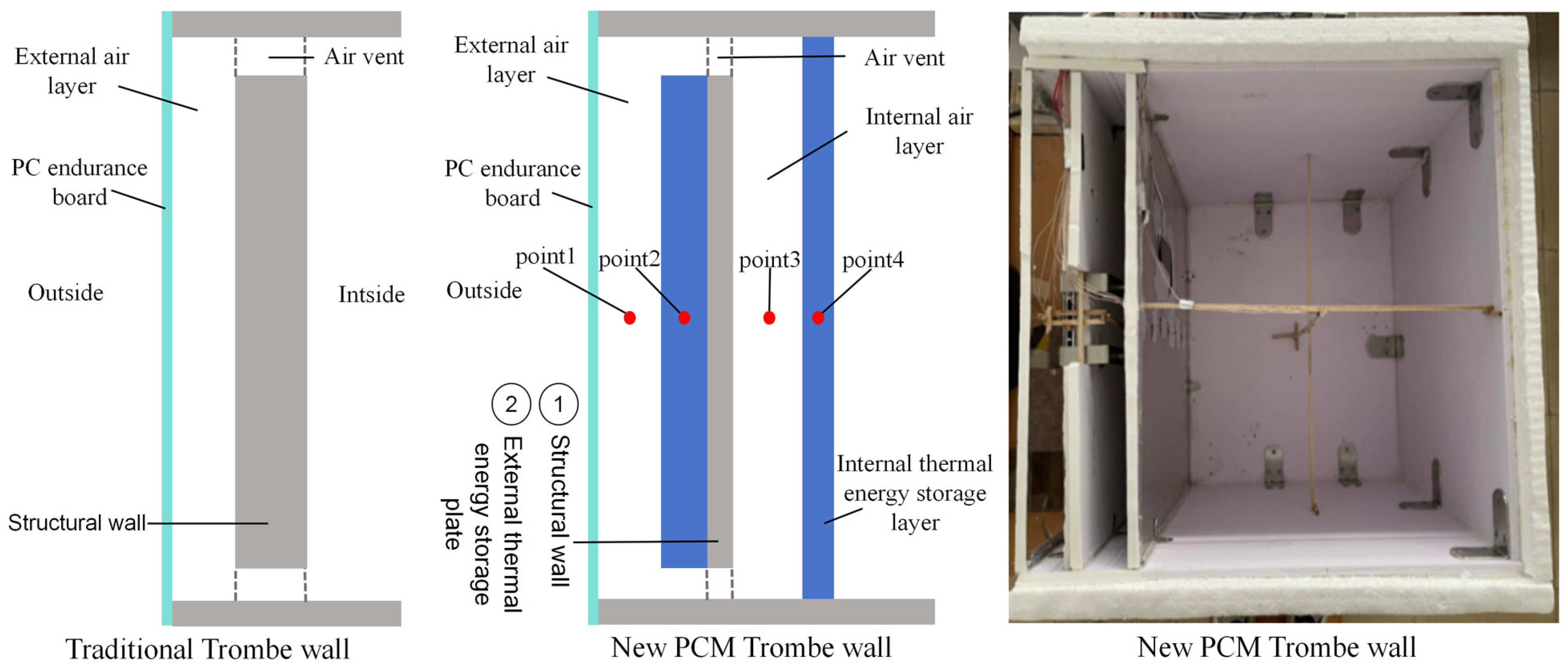
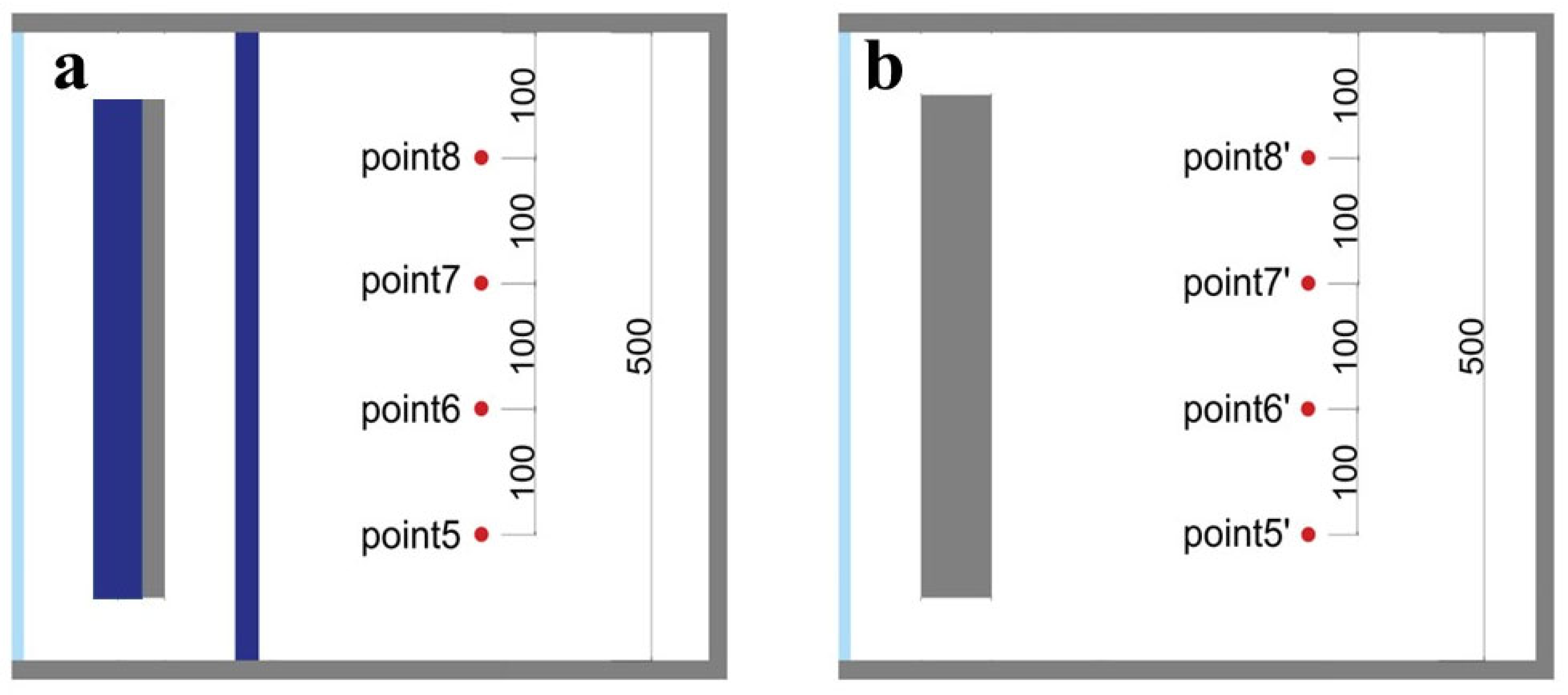
2.1. Model Structural Design

The experimental chamber model is illustrated in Figure 1. Each structural layer was secured with metal fasteners. The internal dimensions were 0.5 × 0.5 × 0.5 m. From outside to inside, the structures consist of a polycarbonate (PC) endurance board (0.5 × 0.5 × 0.005 m), an external air layer (0.03 m), an external thermal storage layer (0.5 × 0.4 × 0.02 m), a structural wall (0.5 × 0.5 × 0.009 m), an internal air layer (0.03 m), and an internal thermal storage layer (0.5 × 0.5 × 0.015 m). The other envelopes were made of a poly vinyl chloride (PVC) panel (0.009 m) and expandable polystyrene (EPS) (0.03 m).

2.2. Experimental Apparatus

The experiment employed the T-type thermocouple as the temperature measuring element, which has the advantages of a simple structure, high reliability and sensitivity, as well as an extensive measuring range. Thermocouples are passive sensors that require other supporting instruments for temperature measurements. Table 1 presents a list of the experimental instruments employed.
Paraffin was selected as the phase change material with a small addition of expanded graphite (2 wt%) to enhance its thermal conductivity. The Paraffin was procured from Shanghai Rushang Phase Change Materials Co., Ltd. (Shanghai, China). The heat storage plate was welded using aluminum plates to form uncovered boxes. The PCM was encapsulated in the thermal storage plate. Table 2 shows the parameters of the phase change materials. PCM1 served as the external thermal storage layer while PCM2 functioned as the internal heat storage layer.

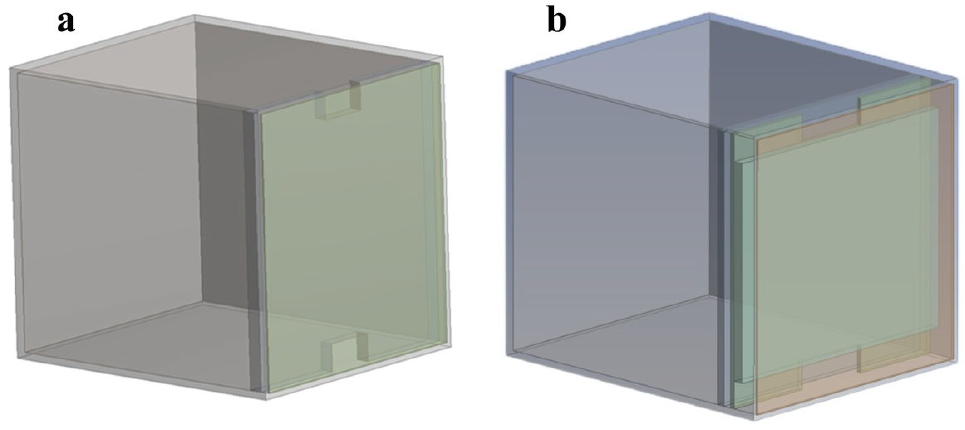
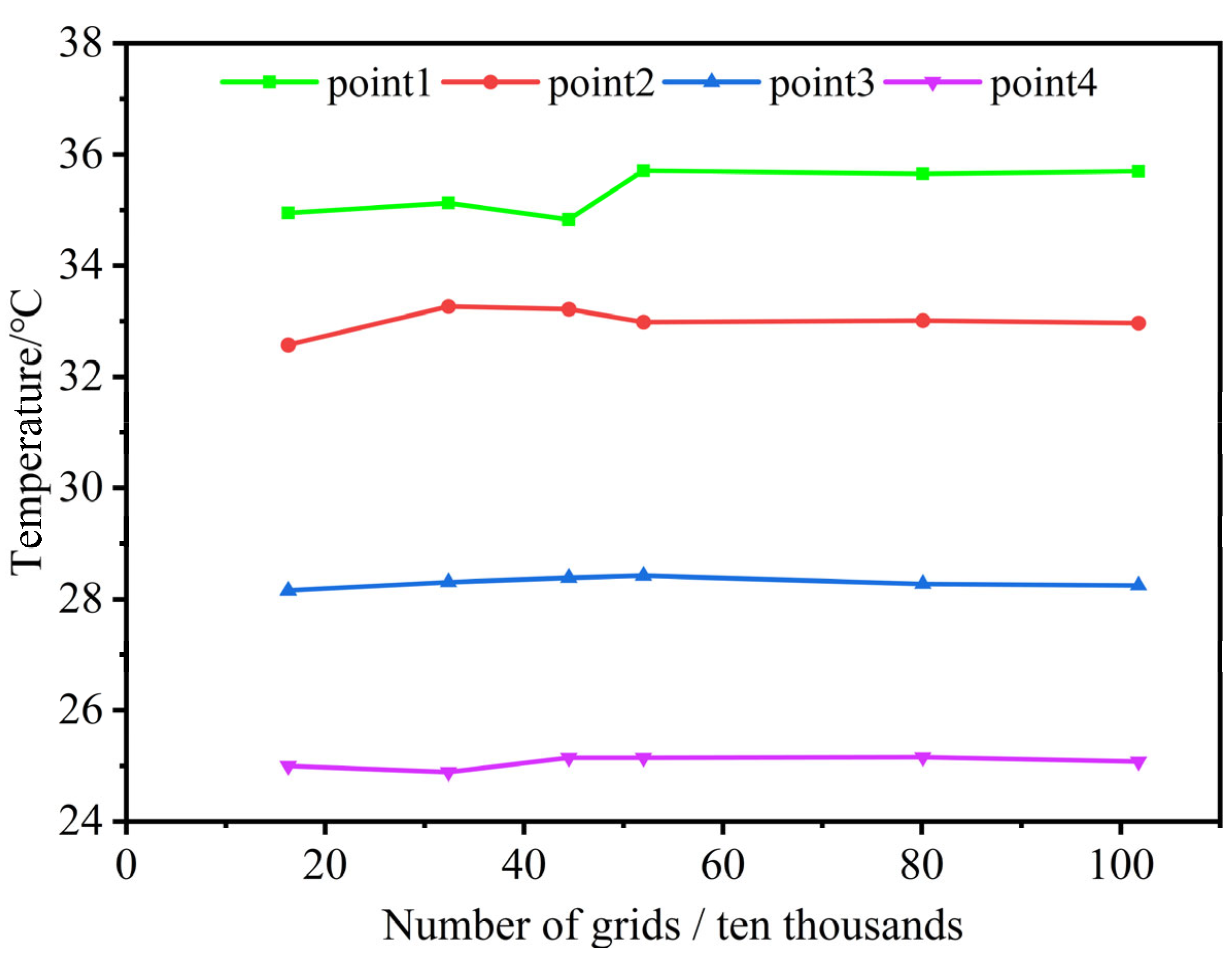
2.3. Numerical Model

The ANSYS Fluent 19.2 software was employed to conduct numerical simulations. Figure 2 shows numerical models of the traditional and new PCM Trombe walls. The dimensions of the Trombe wall were the same as the experimental chamber. In order to establish the numerical model for the traditional Trombe wall, an equal-thickness wall was utilized instead of a thermal storage layer. The material composition of the traditional Trombe wall was identical to that of the structural wall in the new PCM Trombe wall, both utilizing polyvinyl chloride (PVC). The dimensions of the polycarbonate endurance plate, air vent size, and the thickness of the air layer in the traditional Trombe wall were equivalent to those in the new PCM Trombe wall. Additionally, the thickness of the structural wall in the traditional Trombe wall was designed to equal the combined thickness of the external thermal energy storage layer and the structural wall in the new phase change Trombe wall.
The boundary of PC endurance board is mixed boundary condition, namely radiation and convection condition. The surface of the outer heat storage layer was heated using a polyimide heating film, so it was set to the heat flow boundary condition. The roof, floor, and other walls were insulated using EPS, so they were set to the adiabatic boundary condition. The internal temperature of the model was consistent with the ambient temperature at the start of the simulation. The governing equations are as follows: (1)–(10):
Mass conservation equation:
ρ t + x i ρ v i = 0
where ρ is air density (kg/m3), t is time, v is fluid velocity (m/s), and xi is the velocity components in the x, y, z directions (m/s).
Momentum equation:
t ρ v + ρ ν v = μ e f f v p + S m
μ e f f = μ + μ t
where μeff is the effective diffusion coefficient (kg/(m·s)), Sm is the source term of the momentum equation, μ is power viscosity (kg/(m·s), and μt is the fluid turbulent viscosity coefficient (kg/(m·s)).
Energy equation:
t ρ H + ρ v H = k H + S e
k = λ c p
H = h + f L
where H is a specific enthalpy (kJ/kg), cp is a specific heat (J/(kg·K)), h is a sensible heat (kJ/kg), L is the latent heat from the phase change (kJ/kg), Se is the source term of the energy equation, λ is thermal conductivity (W/(m·K)), and f is the liquid fraction. The function f can be defined as follows:
f = 0   if   T < T s o l i d u s 1   if   T > T l i q u i d u s T T s o l i d u s T l i q u i d u s - T s o l i d u s   if   T s o l i d u s < T < T l i q u i d u s
where Tsolidus is the solidification temperature, and Tliduidus is the melting temperature. For pure materials, Tsolidus and Tliduidus are equal.
Enthalpy equations:
ρ H t = λ 2 T
T =             H c s                 ,           H < H s H + ( T m l ) L 2 l c s + L 2 l     ,    H s H H l T m + l + H H l c l   ,      H > H l
H s = c s ( T m l )
H l = c s ( T m + l ) + L
where Tm is the phase transition temperature (K), cs is the average specific heat capacity in the solid phase (J/(kg·K)), cl is the average specific heat capacity in the liquid phase (J/(kg·K)), l is the phase change temperature radius (K), Hl is the specific enthalpy of the saturation of the liquid phase (J/kg), and Hs is the specific enthalpy of the saturation of the solid phase (J/kg).
The numerical simulation of the PCM Trombe wall involves complex phase change processes and natural convection. The following assumptions were made during the numerical simulation:
  • The phase change paraffin used is assumed to be homogeneous and isotropic;
  • The melted PCM is treated as an incompressible Newtonian fluid;
  • The liquid phase portion of the PCM satisfies the Boussinesq assumption.
A suitable number of grids needs to be determined to ensure computational accuracy and improve computational efficiency. The grid numbers 163,000, 324,000, 445,000, 520,000, 801,000, and 1,018,000 were selected for analysis. The results are shown in Figure 3. After one hour of thermal energy storage under identical boundary conditions, the temperature values at the four monitoring points (Figure 1) were examined individually. Among the grid numbers tested, it was found that the grid number of 520,000 satisfies both the requirements for computational accuracy and speed.
The surface of the external thermal energy storage layer was coated with an electric heating film, providing a constant heat flux of 300 W/m2. The duration of thermal energy storage was set to 7 h, while the release time spanned over 17 h. Figure 4 presents a comparison between experimental and simulated results regarding temperature measurements at the four monitoring points. There is only a slight deviation between the simulated values and the measured values, and the numerical results may reflect the variations observed in the measured data.

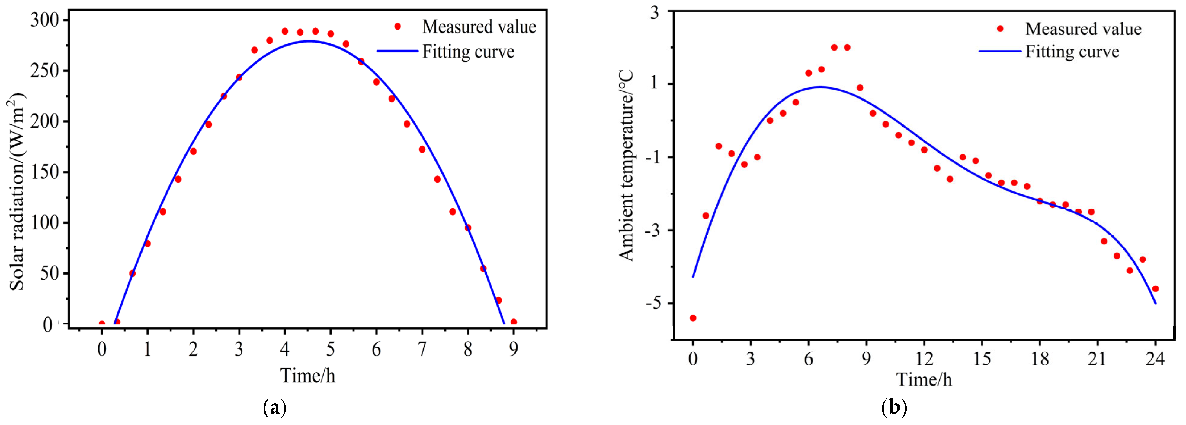
2.4. Meteorological Condition

The meteorological parameters of Qinhuangdao, Hebei Province, China, on 1 December 2023 were selected as the periodic boundary conditions for this study. Meteorological data were collected from a local weather station. The minimum ambient temperature recorded was −5.4 °C, while the maximum temperature reached 2 °C. The peak radiation appeared around noon at approximately 12:00 and reached an intensity of 289 W/m2.
A fitted curve was generated to represent the measured radiation intensity values. Piecewise function fitting was employed to derive functional equations (Equation (12)) that described the fitting curve relationship between time and solar radiation intensity. When t < 0.43 or t > 8.7, the radiation intensity is 0 W/m2.
y 1 = 37.08062 + 139.55822 t 15.39565 t 2   ( 0.43     t     8.7 )
where t is time (hour), and y1 is the solar radiation intensity. The fitted curve of radiation intensity is shown in Figure 5a. The area enclosed by this curve represents a total solar radiation value of 1141 kJ.
The same approach was employed to derive Equation (13), which represents the curve fitting equation for ambient temperature. Figure 5b illustrates the fitting curve of ambient temperature (y2).
y 2 = 4.27574 + 1.76225 t 0.16631 t 2 + ( 8.17319 e 4 ) t 3 + ( 3.6712 e 4 ) t 4 ( 1.00877 e 5 ) t 5
y1 and y2 were set as the boundary conditions of the PC endurance board (Figure 1): y1 is the heat-flux and y2 is the boundary temperature. They were incorporated into the numerical model using a User-Defined Function (UDF).

3. Results and Discussion

The indoor air velocity and temperature are crucial indicators for assessing indoor thermal comfort. In order to comprehensively analyze the thermal performance of both the new PCM Trombe wall and the traditional Trombe wall, the numerical model is employed to simulate and analyze the temperature field and velocity field.

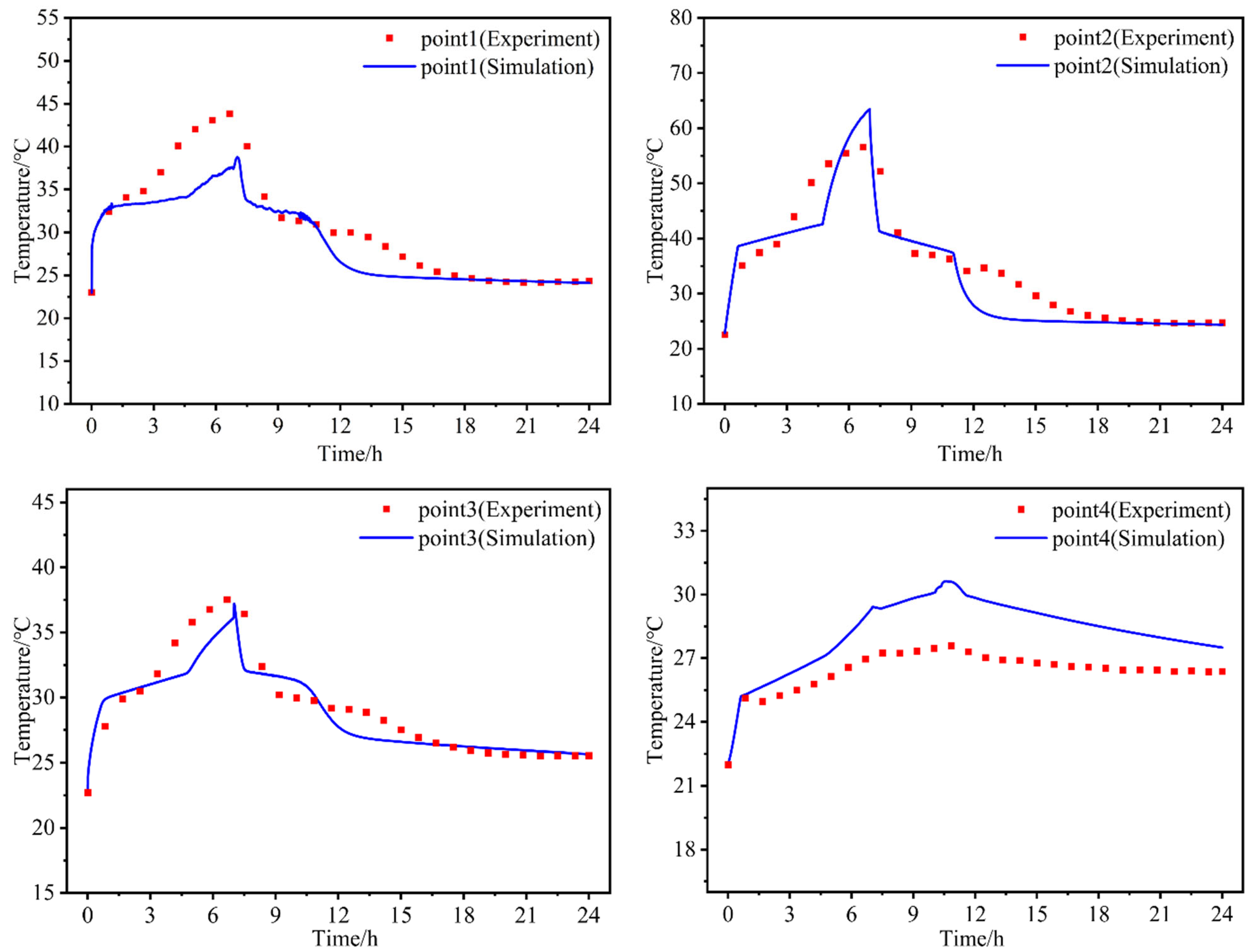
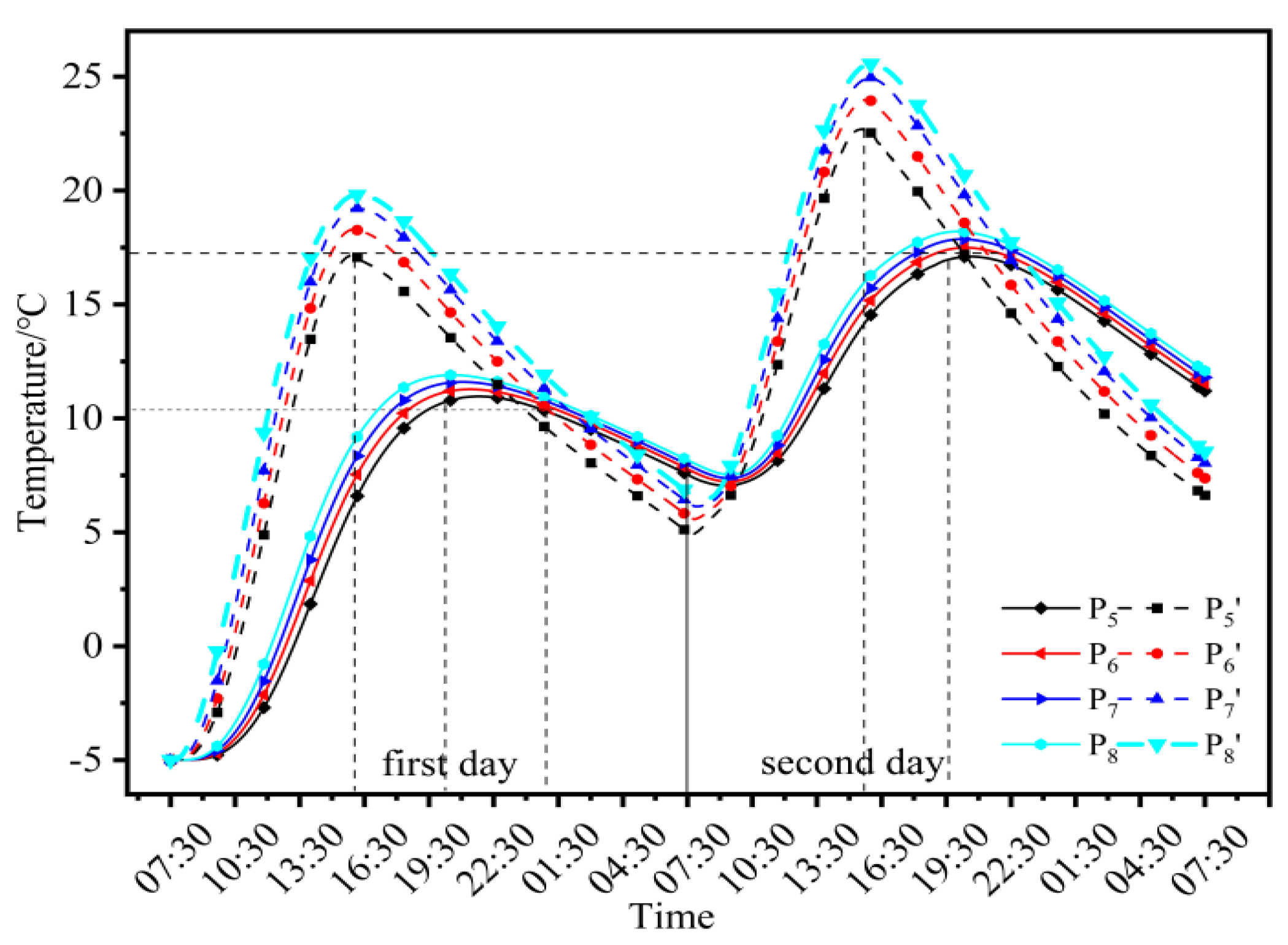
3.1. Analysis of Indoor Temperature

In order to analyze the simulation results, temperature measurement points were set in the numerical models of the new PCM Trombe wall and the traditional Trombe wall, as shown in Figure 6.
Figure 7 shows the indoor air temperature variation when the new PCM Trombe wall and the traditional Trombe wall were used. With the increase in radiation intensity and ambient temperature, the indoor temperature increased rapidly at an average rate of 3.06 °C/h when the traditional Trombe was used. The peak value of the indoor temperature was reached at 15:50. The indoor temperatures were 19.8 °C at the upper point P8′ and 17.1 °C at the lower point P5′. When the new PCM Trombe wall was used, the indoor temperature increased more slowly, at an average rate of 2.13 °C/h. The peak temperature was reached at 20:00. The indoor temperature at the upper point P8′ was 11.9 °C, and at the lower point P5 it was 10.9 °C. Compared with the traditional Trombe wall, it took approximately four additional hours for the new PCM Trombe wall to reach its peak indoor temperature. On the second day, the traditional Trombe wall exhibited maximum and minimum average indoor temperatures of 24.5 °C and 6.8 °C, respectively. In contrast, the new PCM Trombe wall demonstrated maximum and minimum indoor temperatures of 17.2 °C and 7.3 °C, respectively.
During the thermal release stage, the traditional Trombe wall exhibits an indoor temperature difference of 2.45 °C between its upper and lower points. In contrast, the indoor temperature difference between the upper and lower of the new PCM Trombe wall is 0.66 °C, and the temperature uniformity indoors during the thermal release stage is better. This improvement can be attributed to the internal thermal storage layer blocking the indoors from the outdoors, reducing the influence of the outside cold air on the indoor environment during the thermal release stage. This shows that the new PCM Trombe wall can reduce the indoor temperature stratification phenomenon and has a better indoor environment regulation ability than the traditional Trombe wall. At the end of the thermal release stage, the average indoor temperatures using the new PCM Trombe wall and the traditional Trombe wall are 12.2 and 8.3 °C, respectively.
As shown in Figure 7, the rate of decrease in the indoor temperature with the new PCM Trombe wall is significantly lower than that with the traditional Trombe wall at night. The average rate of decrease in the temperature with the traditional wall and the new PCM Trombe wall are 0.853 °C/h and 0.242 °C/h. After the thermal release, the indoor temperature of the new PCM Trombe wall is higher than that of the traditional Trombe wall. In order to better evaluate the thermal insulation performance of the new PCM Trombe wall, the relative fluctuation number proposed by Kong et al. [26] was adopted. The relative fluctuation number is the ratio of the indoor temperature fluctuation coefficient to the outdoor temperature fluctuation coefficient. It can be used to assess the stability of the indoor environment. A higher fluctuation value indicates a poorer thermal insulation performance of a given wall type. The method for calculating the relative fluctuation number is as follows:
T v i = T σ i T a i
T v o = T σ o T a o
V r = T v i T v o
where Tvi is the indoor temperature fluctuation factor, Tσi is the standard deviation of the indoor temperature, Tai is the average indoor temperature, Tvo is the outdoor temperature fluctuation coefficient, Tσo is the standard deviation of the outdoor temperature, Tao is the average outdoor temperature, and Vr is the relative fluctuation number.
The relative fluctuation numbers of the conventional Trombe wall and the new PCM Trombe wall are shown in Table 3. The relative fluctuation number of the new PCM Trombe wall is much smaller than the traditional Trombe wall. This shows that the thermal insulation performance of the new PCM Trombe wall is better, which can better reduce the fluctuation in the indoor temperature and improve indoor thermal comfort. The risk of indoor overheating can be reduced to a greater extent in summer.

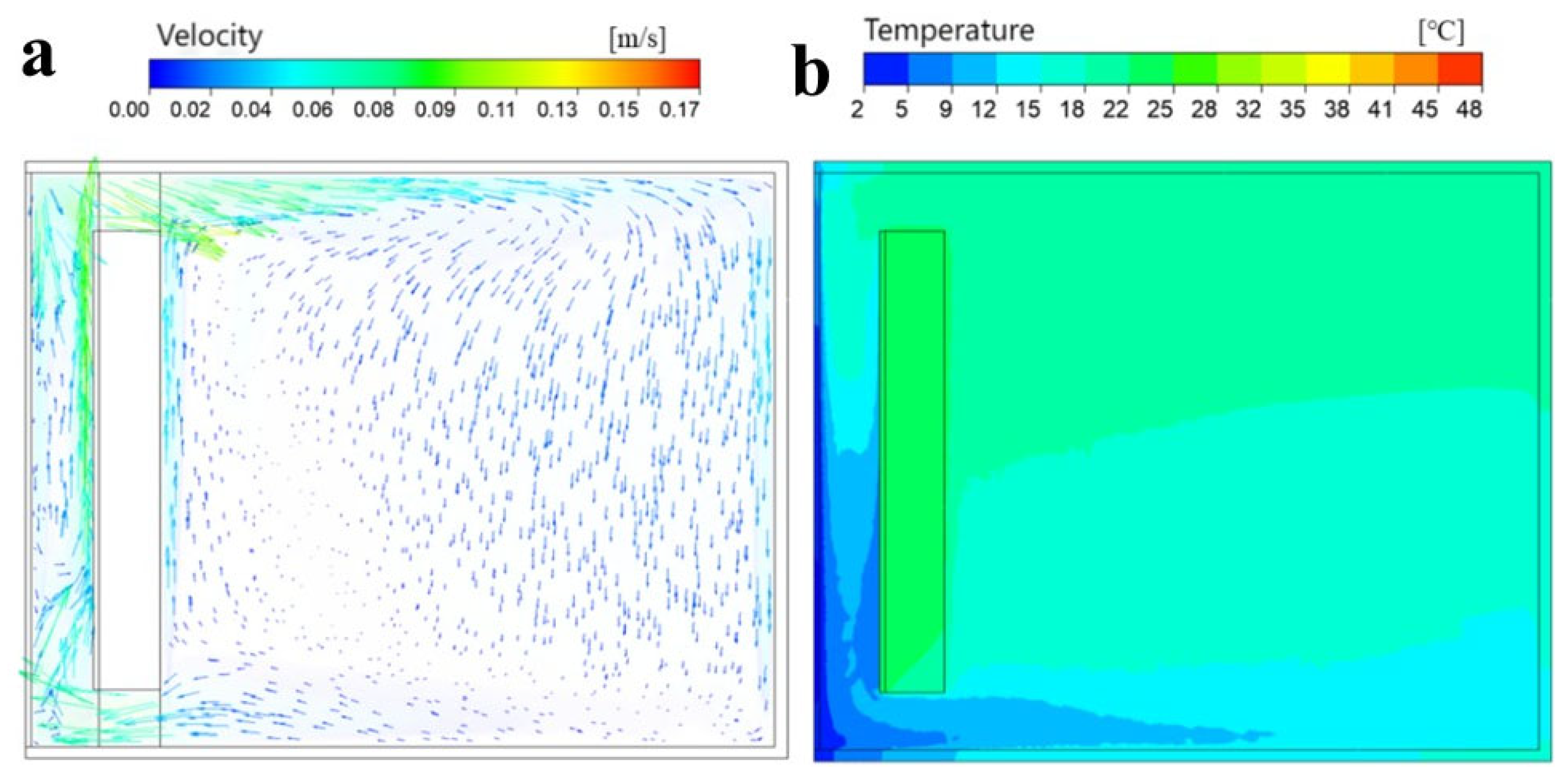
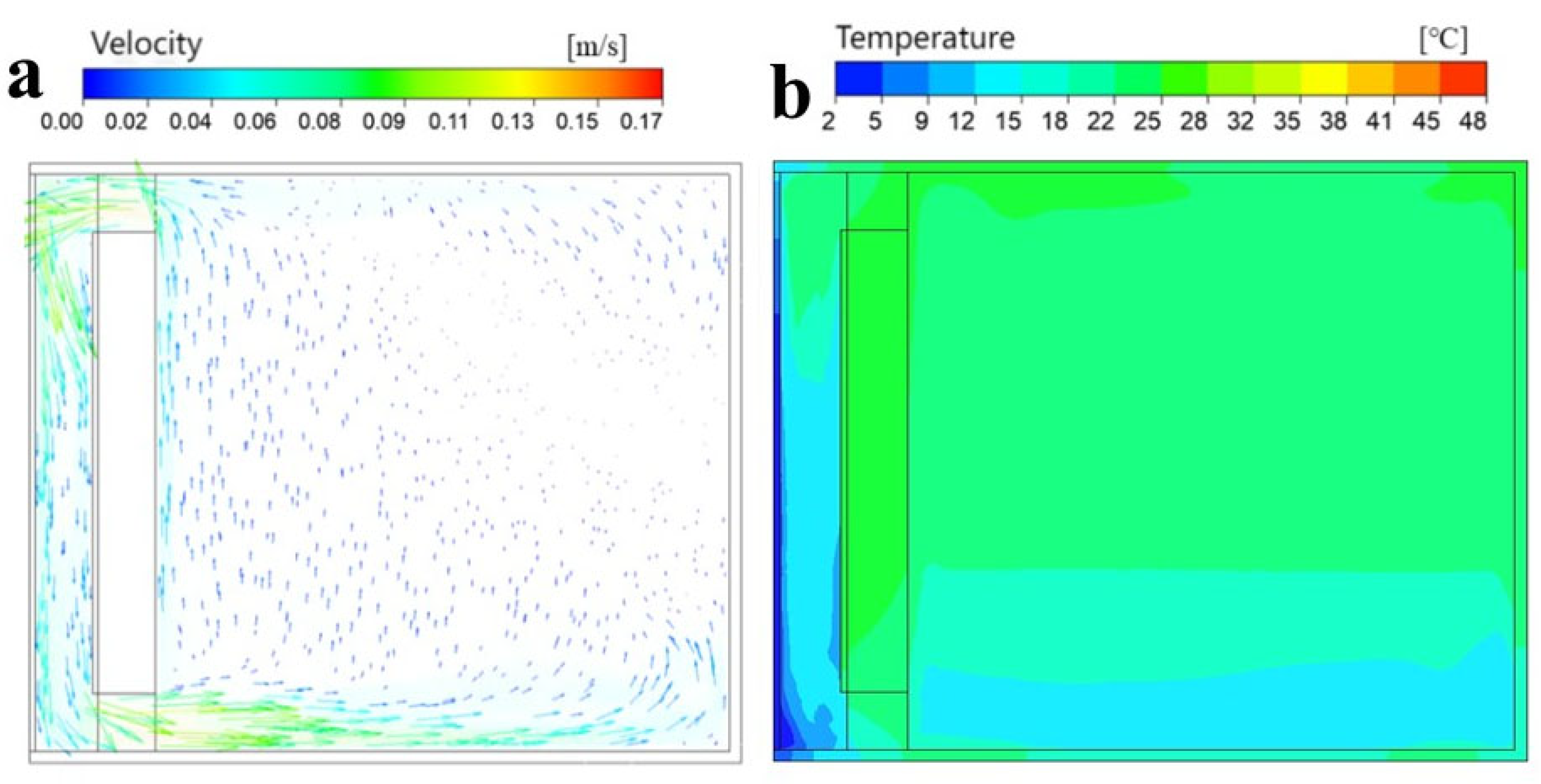
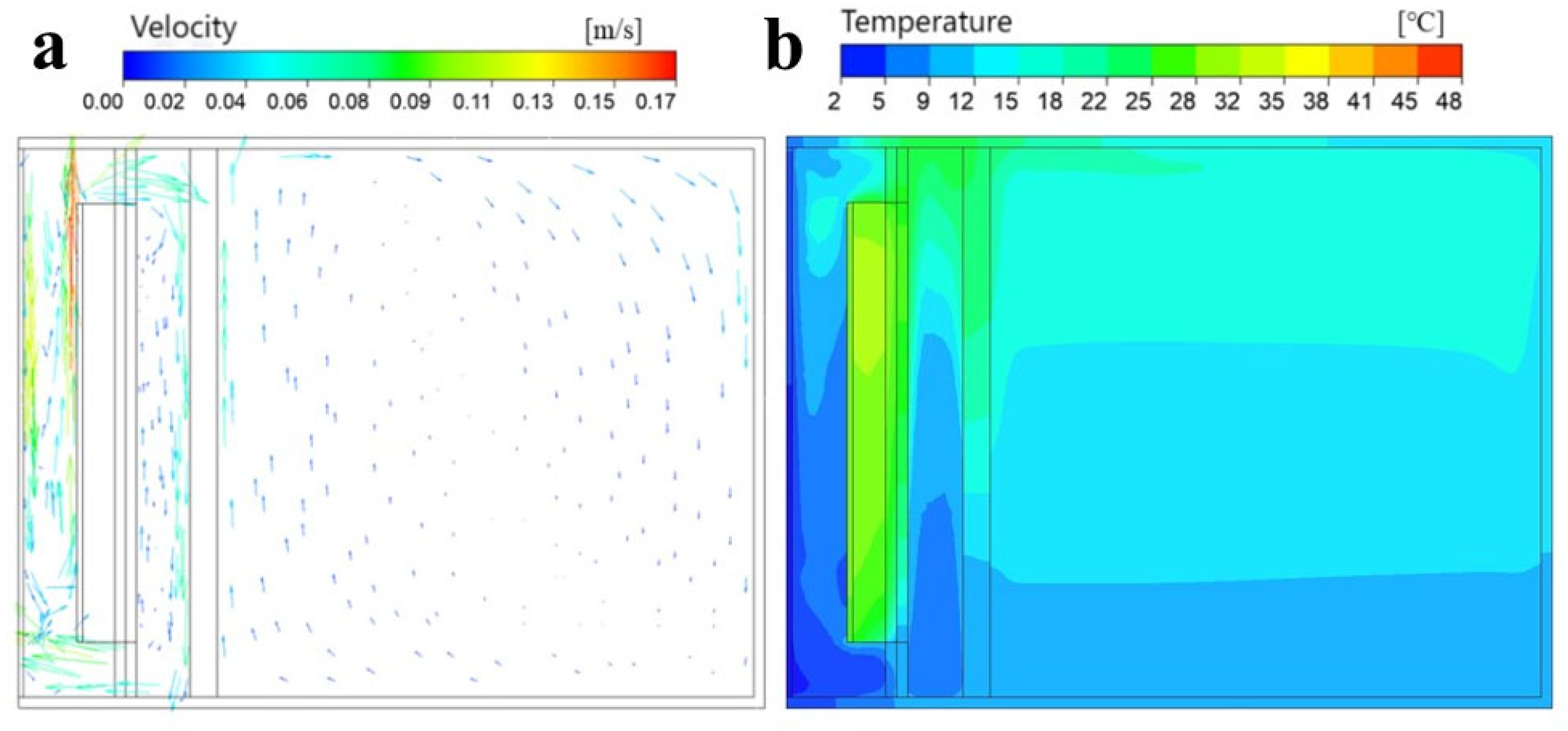
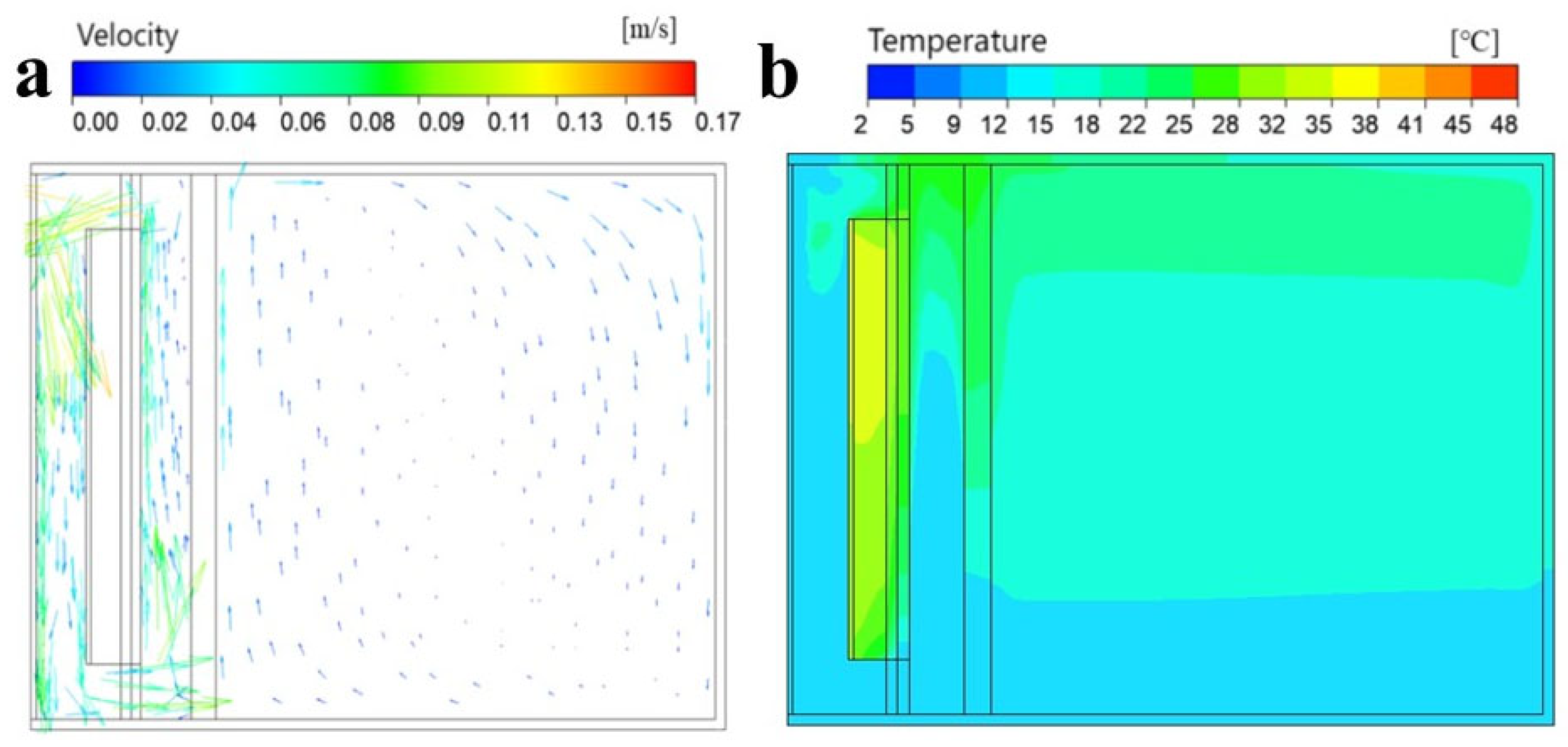
3.2. Analysis of Indoor Velocity

An analysis of the indoor air velocity was conducted on the second day. Figure 8 shows a velocity vector map and temperature cloud map for the traditional Trombe wall at 13:00 during the thermal storage stage. The airflow velocity of the traditional Trombe wall indoor space mainly depends on the temperature difference between the air layer and the indoor air. During thermal storage stage, there is minimal disparity between the air layer and indoor ambient temperatures, with a maximum velocity of 0.24 m/s observed at both the upper and lower vents.
Figure 9 shows a velocity vector map and temperature cloud map for the traditional Trombe wall at 17:00 during thermal release stage. Due to the rapid decrease in the air layer temperature, the indoor air produces a large amount of reflux. The indoor air enters the air layer from the upper vent and returns to the indoors from the lower vent. Therefore, the air velocity in the upper and lower vents is larger, and the highest velocity appears in the lower outlet, which is 0.28 m/s, resulting in a higher air velocity in the lower indoor space.
Figure 10 shows a velocity vector map and temperature cloud map for the PCM Trombe wall at 13:00 during the thermal storage stage. The maximum air velocity is also concentrated near the vents and the thermal storage layer, and the maximum air velocity is close to 0.25 m/s. The indoor air velocity is relatively uniform, and higher wind speeds are mainly found on the inner surface of the internal thermal storage layer, reaching a maximum value of 0.08 m/s. As shown in the temperature cloud map, heat gradually transfers to other areas of the room through airflow. Figure 11 shows a velocity vector map and temperature cloud map for the PCM Trombe wall at 17:00 during the thermal release stage. The air in the air layer begins to recirculate, with the highest air velocity observed at the upper and lower vents, reaching approximately 0.2 m/s. The indoor air velocity is relatively uniform, with the maximum value still found on the inner wall of the internal thermal storage layer, measuring 0.07 m/s. The distribution of indoor temperature is also relatively uniform due to this consistent airflow pattern, thereby avoiding excessive local temperature differences.
In summary, the air velocity at the ventilation outlet in the traditional Trombe wall is larger during both the thermal storage and thermal release stages, resulting in potential discomfort due to excessive airflow in the main activity areas of a room. Conversely, only the air velocity within the air layer of the new PCM Trombe wall increases during these stages, leading to a more uniform indoor velocity field. Consequently, this promotes a relatively even distribution of temperature throughout the room without significant local variations, thereby enhancing indoor thermal comfort. These findings demonstrate that compared to its traditional counterpart, the new PCM Trombe wall exhibits a superior performance in terms of indoor air velocity uniformity and temperature consistency.

4. Conclusions

In this study, a novel double-layer PCM Trombe wall was proposed, and transient simulations were conducted to evaluate its thermal performance. The indoor temperature and velocity were studied, and the main conclusions are:
(1)
Compared to the traditional Trombe wall, the peak temperature time in the new PCM Trombe wall is delayed by 4 h, and the relative fluctuation number is reduced by 68.4%. The indoor temperature distribution of the new PCM Trombe wall is more uniform, and its thermal insulation performance is better.
(2)
The new PCM Trombe wall exhibited good thermal storage and thermal preservation performances. At the end of the thermal release stage, the average indoor temperatures with the new PCM Trombe wall and the traditional Trombe wall were 12.2 °C and 8.3 °C, respectively. The traditional Trombe wall exhibited maximum and minimum average indoor temperatures of 24.5 °C and 6.8 °C, respectively. In contrast, the new PCM Trombe wall demonstrated maximum and minimum indoor temperatures of 17.2 °C and 7.3 °C, respectively. The relative fluctuation number of the new PCM Trombe wall was 0.8, which is much smaller than the relative fluctuation number of 2.534 for the traditional Trombe wall.
(3)
The internal thermal storage layer of the new PCM Trombe wall can significantly reduce the indoor air velocity and improve the thermal comfort of the room. The maximum velocity of air in the new PCM Trombe wall is 0.08 m/s lower than that of the traditional Trombe wall.

Author Contributions

All authors contributed equally to the preparation of this manuscript. All authors have read and agreed to the published version of the manuscript.

Funding

This research was funded by the Central Leading Local Science and Technology Development Fund Project (No. 246Z3609G).

Institutional Review Board Statement

Not applicable.

Informed Consent Statement

Not applicable.

Data Availability Statement

Data are contained within the article.

Conflicts of Interest

The author(s) declare no potential conflicts of interest with respect to the research, authorship, and/or publication of this article.

References

  1. Li, G.; Li, M.; Taylor, R.; Hao, Y.; Besagni, G.; Markides, C.N. Solar energy utilisation: Current status and roll-out potential. Appl. Therm. Eng. 2022, 209, 118285. [Google Scholar] [CrossRef]
  2. Yin, Y.; Chen, H.; Zhao, X.; Yu, W.; Su, H.; Chen, Y.; Lin, P. Solar-absorbing energy storage materials demonstrating superior solar-thermal conversion and solar-persistent luminescence conversion towards building thermal management and passive illumination. Energy Convers. Manag. 2022, 266, 115804. [Google Scholar] [CrossRef]
  3. Kolani, K.; Wang, Y.; Zhou, D.; Nouyep Tchitchui, J.U.; Okolo, C.V. Passive building design for improving indoor thermal comfort in tropical climates: A bibliometric analysis using citespace. Indoor Built Environ. 2023, 32, 1095–1114. [Google Scholar] [CrossRef]
  4. Ismail, R.M.; Megahed, N.A.; Eltarabily, S. A conceptual framework for phase change material integration in building components. Indoor Built Environ. 2023, 32, 1115–1139. [Google Scholar] [CrossRef]
  5. Wang, Z.; Liu, C.; Yao, P.; Fu, X. Measurement of the indoor environment and heating energy consumption of a passive office building in severely cold region, China. Indoor Built Environ. 2024, 33, 1705–1722. [Google Scholar] [CrossRef]
  6. Si, P.; Lv, Y.; Rong, X.; Shi, L.; Yan, J.; Wang, X. An innovative building envelope with variable thermal performance for passive heating systems. Appl. Energy 2020, 269, 115175. [Google Scholar] [CrossRef]
  7. Barone, G.; Buonomano, A.; Forzano, C.; Giuzio, G.F.; Palombo, A. Passive and active performance assessment of building integrated hybrid solar photovoltaic/thermal collector prototypes: Energy, comfort, and economic analyses. Energy 2020, 209, 118435. [Google Scholar] [CrossRef]
  8. Qiu, Z.; Wang, J.; Yu, B.; Liao, L.; Li, J. Identification of passive solar design determinants in office building envelopes in hot and humid climates using data mining techniques. Build. Environ. 2021, 196, 107566. [Google Scholar]
  9. Wu, Y.; Yu, S.; Wang, C.; Chen, Q.; Ming, T. The use of a thermal diode bridge for passive temperature control in the built environment during the heating seasons—An analytical study. Energy 2023, 262, 125289. [Google Scholar] [CrossRef]
  10. Albayyaa, H.; Hagare, D.; Saha, S. Energy conservation in residential buildings by incorporating passive solar and energy efficiency design strategies and higher thermal mass. Energy Build. 2019, 182, 205–213. [Google Scholar] [CrossRef]
  11. Yu, Z.; Gou, Z.; Qian, F.; Fu, J.; Tao, Y. Towards an optimized zero energy solar house: A critical analysis of passive and active design strategies used in solar decathlon europe in madrid. J. Clean. Prod. 2019, 236, 117646. [Google Scholar]
  12. Briga-Sá, A.; Leitão, D.; Boaventura-Cunha, J.; Martins, F.F. Trombe wall thermal performance: Data mining techniques for indoor temperatures and heat flux forecasting. Energy Build. 2021, 252, 111407. [Google Scholar]
  13. Elsaid, A.M.; Hashem, F.A.; Mohamed, H.A.; Ahmed, M.S. The energy savings achieved by various trombe solar wall enhancement techniques for heating and cooling applications: A detailed review. Sol. Energy Mater. Sol. Cells 2023, 254, 112228. [Google Scholar]
  14. Kou, F.; Shi, S.; Zhu, N.; Song, Y.; Zou, Y.; Mo, J.; Wang, X. Improving the indoor thermal environment in lightweight buildings in winter by passive solar heating: An experimental study. Indoor Built Environ. 2022, 31, 2257–2273. [Google Scholar]
  15. Xiong, Q.; Alshehri, H.M.; Monfaredi, R.; Tayebi, T.; Majdoub, F.; Hajjar, A.; Delpisheh, M.; Izadi, M. Application of phase change material in improving Trombe wall efficiency: An up-to-date and comprehensive overview. Energy Build. 2022, 258, 111824. [Google Scholar]
  16. Wang, D.; Hu, L.; Du, H.; Liu, Y.; Huang, J.; Xu, Y.; Liu, J. Classification, experimental assessment, modeling methods and evaluation metrics of Trombe walls. Renew. Sustain. Energy Rev. 2020, 124, 109772. [Google Scholar]
  17. Zhou, L.; Huo, J.; Zhou, T.; Jin, S. Investigation on the thermal performance of a composite Trombe wall under steady state condition. Energy Build. 2020, 214, 109815. [Google Scholar]
  18. Yu, B.; Yang, J.; He, W.; Qin, M.; Zhao, X.; Chen, H. The performance analysis of a novel hybrid solar gradient utilization photocatalytic-thermal-catalytic-Trombe wall system. Energy 2019, 174, 420–435. [Google Scholar]
  19. Sergei, K.; Shen, C.; Jiang, Y. A review of the current work potential of a Trombe wall. Renew. Sustain. Energy Rev. 2020, 130, 109947. [Google Scholar]
  20. Xu, B.; Gan, W.; Wang, Y.; Chen, X.; Fei, Y.; Pei, G. Thermal performance of a novel Trombe wall integrated with direct absorption solar collector based on phase change slurry in winter. Renew. Energy 2023, 213, 246–258. [Google Scholar]
  21. Zhu, N.; Deng, R.; Hu, P.; Lei, F.; Xu, L.; Jiang, Z. Coupling optimization study of key influencing factors on PCM Trombe wall for year thermal management. Energy 2021, 236, 121470. [Google Scholar] [CrossRef]
  22. Pan, S.; Cao, B.; Yuan, D.; Jiao, T.; Zhang, Q.; Tang, S. Complexes of cupric ion and tartaric acid enhanced calcium peroxide fenton-like reaction for metronidazole degradation. Chin. Chem. Lett. 2024, 35, 109185. [Google Scholar] [CrossRef]
  23. Liu, Y.; Zheng, J.; Deng, Y.; Wu, F.; Wang, H. Effect of functional modification of porous medium on phase change behavior and heat storage characteristics of form-stable composite phase change materials: A critical review. J. Energy Storage 2021, 44, 103637. [Google Scholar] [CrossRef]
  24. Chang, Z.; Wang, K.; Wu, X.; Lei, G.; Wang, Q.; Liu, H.; Wang, Y.; Zhang, Q. Review on the preparation and performance of paraffin-based phase change microcapsules for heat storage. J. Energy Storage 2022, 46, 103840. [Google Scholar] [CrossRef]
  25. Xiao, Y.; Zhang, T.; Liu, Z.; Fei, F.; Fukuda, H. Optimizing energy efficiency in HSCW buildings in China through temperature-controlled PCM Trombe wall system. Energy 2023, 278, 128015. [Google Scholar] [CrossRef]
  26. Kong, X.; Li, J.; Fan, M.; Li, W.; Li, H. Study on the thermal performance of a new double layer PCM Trombe wall with multiple phase change points. Sol. Energy Mater. Sol. Cells 2022, 240, 111685. [Google Scholar] [CrossRef]
  27. Liu, X.; Zhou, Y.; Zhang, G. Numerical study on cooling performance of a ventilated trombe wall with phase change materials. Build. Simul. 2018, 11, 677–694. [Google Scholar] [CrossRef]
  28. Sheikholeslami, M.; Al-Hussein, H.R. Modification of heat storage system involving Trombe wall in existence of paraffin enhanced with nanoparticles. J. Energy Storage 2023, 58, 106419. [Google Scholar] [CrossRef]
  29. Liu, Y.; Hou, L.; Yang, Y.; Feng, Y.; Yang, L.; Gao, Q. Effects of external insulation component on thermal performance of a Trombe wall with phase change materials. Sol. Energy 2020, 204, 115–133. [Google Scholar] [CrossRef]
  30. Zhou, S.; Bai, F.; Razaqpur, G.; Wang, B. Effect of key parameters on the transient thermal performance of a building envelope with Trombe wall containing phase change material. Energy Build. 2023, 284, 112879. [Google Scholar] [CrossRef]
Figure 1. Structural diagram of the new PCM Trombe wall and traditional Trombe wall.
Coatings 15 00303 g001
Figure 2. (a) Traditional and (b) new PCM Trombe wall numerical model.
Coatings 15 00303 g002
Figure 3. Grid independence verification.
Coatings 15 00303 g003
Figure 4. Numerical model and experimental data validation.
Coatings 15 00303 g004
Figure 5. Fitting curves of (a) radiation intensity and (b) ambient temperature.
Coatings 15 00303 g005
Figure 6. Temperature measurement points in the (a) new and (b) traditional Trombe wall.
Coatings 15 00303 g006
Figure 7. Indoor air temperature variation.
Coatings 15 00303 g007
Figure 8. The indoor (a) velocity and (b) temperature with the traditional Trombe wall at 13:00.
Coatings 15 00303 g008
Figure 9. The indoor (a) velocity and (b) temperature with the traditional Trombe wall at 17:00.
Coatings 15 00303 g009
Figure 10. The indoor (a) velocity and (b) temperature with the PCM Trombe wall at 13:00.
Coatings 15 00303 g010
Figure 11. The indoor (a) velocity and (b) temperature with the PCM Trombe wall 17:00.
Coatings 15 00303 g011
Table 1. List of experimental instruments.
InstrumentModelPrecisionManufacturer
ThermocoupleT-type±0.2 °CShanghai Yulai Instrument Co., Ltd. (Shanghai, China)
Data acquisition instrumentAgilent34972A/YesterTech Co., Ltd. (Beijing, China)
Voltage regulatorTDGC2-1/Zhengtai group Co., Ltd. (Taizhou, China)
Electronic balance/0.1 gKai Fung group Co., Ltd. (Yongkang, China)
Table 2. Parameters of phase change materials.
Materialsρ (kg/m3)λ (W/m·K)cp (J/kg·K)Hm (kJ/kg)Melting Point (°C)
PCM18300.70180016036–40
PCM28300.70210018025–29
Table 3. Relative fluctuation numbers.
TypesTraditional Trombe WallNew PCM Trombe WallOutdoor Air
Parameters
Average temperature10.525 °C9.418 °C−2 °C
Standard deviation of temperature3.6531.1481.378
Indoor/outdoor temperature
fluctuation coefficient
0.0130.0040.005
Relative fluctuation number2.5340.800
Disclaimer/Publisher’s Note: The statements, opinions and data contained in all publications are solely those of the individual author(s) and contributor(s) and not of MDPI and/or the editor(s). MDPI and/or the editor(s) disclaim responsibility for any injury to people or property resulting from any ideas, methods, instructions or products referred to in the content.

