Abstract
Laser processing is an effective and precise micro-structure fabrication technique. At present, micro-structure processing is primarily applied to planar surfaces. However, for curved surfaces, variations in the incident angle of the laser beam lead to distortions in micro-structural morphology. In this study, an experimental investigation was conducted to characterize micro-structural ablation under oblique laser incidence. Initially, a single-factor parametric study was performed on the surface of stainless steel. The results indicate that grooves measuring 45 μm in width and 43 μm in depth were achieved under the conditions of a single-pulse energy of 10 μJ, a laser frequency of 70 kHz, a scanning speed of 10 mm/s, and 20 processing cycles. Subsequently, the influence of the laser incidence angle on groove morphology was further examined. The results demonstrate that for incidence angles below 11°, the groove removal rate approaches 1, and the root mean square of shape error (RMS) remains below 1.5 μm. To reduce the deformation of the micro-structure at oblique incidence, a curve-guided surface projection (CGSP) method was developed, and the micro-dimples were fabricated at laser incidence angles of 10° and 14°. Compared with the conventional direct projection (DP) method, the CGSP approach significantly mitigates structural distortion resulting from oblique incidence. Finally, the CGSP method was applied to fabricate the micro-dimples at various locations on a spherical surface. The removal rates of 0.988 and 0.936 were closer to unity than those achieved via direct projection, while the RMS values were reduced by 56.4% and 76.2%, respectively. These findings offer a promising solution to the challenge of oblique laser incidence in curved micro-structuring and further broaden the application scope of laser processing technology.
1. Introduction
The design and fabrication of functional micro-structures are critical for improving device performance, including anti-fog, anti-icing, and self-cleaning properties for aircraft engine surfaces [1,2,3], negative refraction and stealth characteristics for radar reflectors [4,5,6], wear resistance and lubrication for turbine blades [7,8], and corrosion-resistant coatings for ship surfaces [9,10]. Currently, micro-structure fabrication methods include CNC micro-milling [11], mask chemical etching [12], flexible screen transfer [13,14], and 3D printing [15]; however, these techniques exhibit limitations in material adaptability, scalability, and precision.
Laser technology is widely employed in precision micro-structural machining due to its high power, non-contact nature, precise control, and broad material compatibility. Common micro-structures include periodic structures [16,17], micro-grooves [18,19], micro-holes [20,21], micropillars [22,23], porous structures [24], and hierarchical structures [25,26]. The fabrication of these structures is primarily focused on planar workpieces, with emphasis on the machining process and laser parameters rather than on the orientation of the laser beam. In this configuration, the laser beam is typically directed vertically, enabling patterned structures to be mapped onto a flat surface without distortion via direct projection (DP) methods, ensuring a uniform spot distribution. Although the effects of laser parameters such as energy density, pulse width, and wavelength on the formation of planar structures [27,28] have been extensively studied, laser machining of non-planar surfaces is becoming increasingly critical due to the growing demand for complex curved parts in industrial applications. The inherent curvature of non-planar parts causes the surface normal vector to deviate from the vertical and the positional height to vary across the surface. This leads to distortions in the direct projection pattern, and spot deviations can alter energy distribution, further complicating the fabrication of micro-structures due to these non-laser factors.
To address this challenge, numerous studies have been conducted. Nivas et al. [29] investigated the effect of varying incidence angles on the formation of periodic ripples on silicon surfaces using femtosecond lasers, revealing that changes in incidence angle influenced ripple periodicity. Yang et al. [30] employed varying incidence angles on YG6 cemented carbide to fabricate linear micro-structures with a 200 μm pitch and determined that a 60° incidence angle yielded optimal friction performance. These studies indicate that micro-structural deformation substantially impacts surface functionality under oblique incidence conditions. However, these investigations primarily addressed the optimization of functional structures rather than the microfabrication process itself. Furthermore, Wang et al. [31] demonstrated that high processing accuracy can be preserved when the laser incidence angle remains below a critical threshold.
In micro-structure fabrication, to enhance the accuracy of micro-structural pattern fabrication, certain studies have employed techniques, such as model parameterization and texture mapping [32,33]. This approach typically entails expanding the 3D model into the 2D plane using either conformal parameterization, which minimizes angular distortion, or authalic parameterization, which reduces area distortion. Subsequently, the parameterized 2D plane points are mapped back to the 3D model. Guo et al. [34] employed conformal parameterization to process the entire STL model, achieving effective 2D pattern mapping onto 3D artifacts. Similarly, Luo et al. [35] used conformal parameterization for STL models, projecting 2D machining paths onto 3D surfaces using angle-based flattening (ABF) and edge-based flattening (EBF) methods. Xiao et al. [36] proposed an optimized parameterization method for STL models involving model reconstruction with uniform triangle sizes through resampling, which led to improved parameterization outcomes. Although these methods are capable of projecting patterns onto complex surfaces, much of the research has focused on using STL triangular mesh models, which are typically suited for applications such as 3D printing and marking, where precision is less critical. And, these methods often involve intricate processes and extensive mathematical calculations, which present challenges for system integration. A straightforward approach involves adjusting the height of the 2D pattern and projecting it directly onto the 3D model. However, this method often results in substantial distortions, particularly in areas with pronounced curvature variations. To address this issue, some researchers have employed the equal arc length projection method [37], which alleviates distortion to some extent; however, it still results in considerable local errors on certain general free-form surfaces. Moreover, its implementation relies on commercial software.
Based on the above research status, this study takes 304L stainless steel planar and spherical surfaces as the research object and innovatively introduces the curve-guided surface projection (CGSP) method to systematically investigate the laser ablation characteristics under oblique incidence conditions. Specifically, this study examines the influence of scanning speed, laser frequency, number of scans, and single-pulse energy on groove formation. Building upon these findings, the effect of incidence angle on groove morphology is further analyzed, and the threshold incidence angle for laser processing on stainless steel is identified. Subsequently, utilizing the proposed CGSP method and the determined incidence angle threshold, the micro-dimples were designed and precisely fabricated on inclined and spherical surfaces. This study offers a novel approach to addressing micro-structural fabrication challenges under oblique laser incidence and further expands the potential applications of laser processing technology.
2. Method
2.1. Experimental Setup
The processing device used in this experiment was independently developed by our research group and is shown in Figure 1. The system comprises a picosecond laser, an optical system, and a displacement-rotation platform. A picosecond laser (EdgeWave, Aachen, Germany) operating at a wavelength of 532 nm and a pulse width of 10 ps was employed. The optical system includes a beam expander, a grating, a reflector, and a three-dimensional galvanometer. When emitted, the laser beam undergoes initial expansion before being directed to the beam expander. The expanded beam then traverses two sequential mirrors before reaching the 3D galvanometer at the terminal optical path. The 3D galvanometer comprises a dynamic focusing unit and a 2D galvanometer, which is equipped with an F-theta lens at its base. This system focuses on the laser beam, producing a high-quality Gaussian spot with a 45 μm diameter on the workpiece surface. The workpiece is mounted on a displacement-rotation stage to allow precise positional adjustments. Precise laser processing control is achieved using laboratory-developed computer software, which regulates the movement of the displacement-rotation platform and sets parameters such as scanning speed, frequency, and number of scans. This software is built upon the laboratory’s proprietary LR-EMC laser motion control card and is used exclusively for in-house experiments.
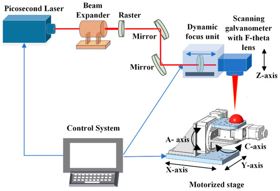
Figure 1.
Experiment setup.
2.2. Curve-Guided Surface Projection
Conventional methods for mapping structural patterns onto surfaces typically employ direct projection (DP), akin to the principle of a parallel light beam propagating along the Z-axis, forming a projection of the pattern onto the surface. This method generates the micro-structural pattern on the surface by directly mapping the two-dimensional coordinate system to the Z-axis. However, this method is prone to significant distortion of the micro-structure on the surface. Therefore, a curve-guided surface projection processing method is necessary to mitigate the distortion. The schematic of this method is illustrated in Figure 2. First, the center of the enclosing box is chosen as a reference point within the pattern structure, and a Cartesian coordinate system is established at this point, denoted as O-xy. Subsequently, the reference point is projected onto the complex surface to obtain the point O-uv, which defines the parametric coordinate system. Next, discretize the micro-structural pattern into several discrete points and compute the Cartesian coordinate distance D between any discrete point P(x0, y0) in the pattern and the reference point O-xy. Then, project the point P onto P(u0, v0), ensuring that the line segment Lxy is mapped onto the curve Luv. Finally, find a point L(u1) on the curve such that the length of the arc from O-uv equals D, and adjust the point P(u0, v0) to L(u1).
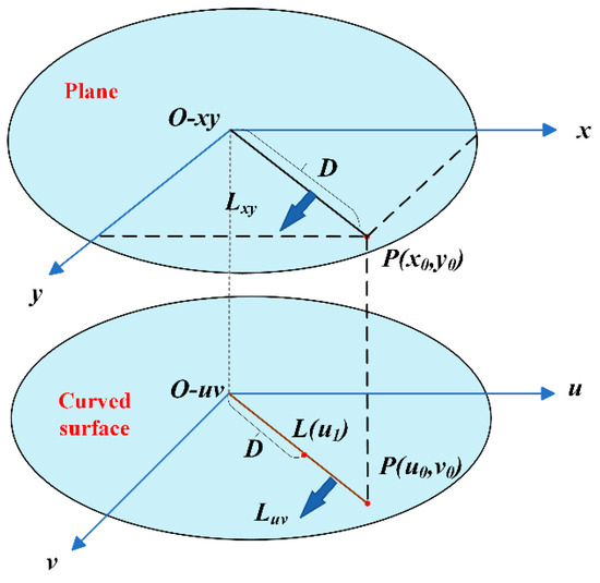
Figure 2.
Schematic of CGSP.
2.3. Experimental Design
2.3.1. Single-Factor Experimental Study on Grooving Processing
Due to the curvature of the surface, the laser interacts with it in a non-perpendicular manner. Therefore, it is essential to investigate the effect of the laser incidence angle on the surface structure before micro-structuring. The groove, being the fundamental unit of the micro-structure, was selected as the object of study for this experiment, with 304 stainless steel (0.5 mm thick) used as the test material. This study investigates the influence of processing time, scanning speed, laser frequency, and single-pulse energy on the depth and width of grooves. Based on this, a set of parameters yielding moderate depth and width, along with improved morphology, was chosen to further investigate the effect of the laser incidence angle on groove characteristics. The specific experimental parameters are provided in Table 1. The term scanning times refers to the number of times the pattern is processed and is a unitless parameter.

Table 1.
Parameters used for the single-factor experimental study on grooving processing.
2.3.2. Experimental Study on Texturing of Inclined Surfaces
After investigating the effect of the laser incidence angle on groove properties, the limiting range was determined to be 11°, and the plane was tilted using a rotating table to simulate non-perpendicular laser incidence. A micro-dimple pattern was designed, as shown in Figure 3, consisting of nine identical regions with 600 μm spacing. Each region features line segments with lengths of 400 μm and spacings of 20 μm, with the laser scanning along each line segment sequentially. The laser scanned along each line segment in turn, with patterns projected onto the inclined plane at 10° and 14° using CGSP and DP methods, respectively. Patterns were also processed on a plane with a 0° inclination angle, serving as the control group (i.e., laser incidence angles of 0°, 10°, and 14°, respectively). The specific experimental parameters are provided in Table 2.
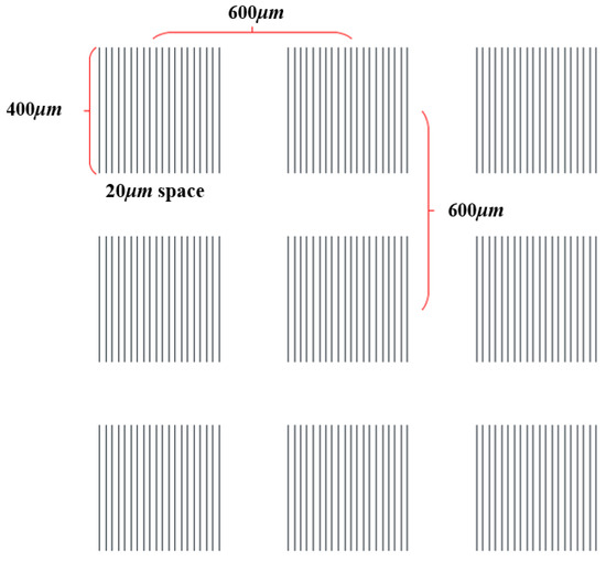
Figure 3.
Design of the micro-structure.
Table 2.
Parameters used for the experimental study on the micro-dimples of inclined surfaces.
2.3.3. Experiment on Micro-Structure Texturing of Spherical Surfaces
A curved surface, in contrast to a slanted surface, has normal vectors that vary in different directions, potentially resulting in multiple angles of incidence within the same design structure. The normal vector of the center point of the enclosing box within the structure is used as a reference, with the maximum laser incidence angle defined as the greatest angle between the normal vector of any point within the structure and the reference normal vector, calculated and solved by software written by the laboratory. To ensure structural stability, the maximum laser incidence angle of the micro-structure must fall within a defined range. The specific experimental parameters are provided in Table 3. Additionally, as shown in Figure 4, under identical micro-structure patterns and laser parameters, a 25 mm diameter 304 stainless steel sphere was selected, and the pattern was projected to different locations on the sphere using DP and CGSP methods, respectively (one at the center and one at the edge of the sphere, chosen as representative locations). Following projection, the maximum incidence angles of each micro-structure are presented in Table 4. The center of the micro-structures was relocated to the center of the galvanometer by shifting and rotating the stage for 3D scanning. A pattern was machined on the plane with a 0° inclination angle, serving as the control group.
Table 3.
Parameters used for the experiments on the micro-structure texturing of spherical surfaces.
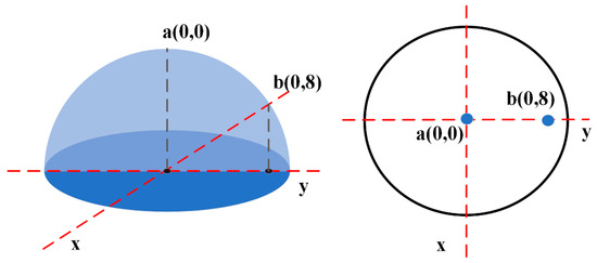
Figure 4.
Location of the micro-structure.
Table 4.
Maximum incidence angles.
2.3.4. Characterization and Measurement Methods
After the machining process was completed, the samples were first ultrasonically cleaned using anhydrous ethanol and then dried with oil-free compressed air. Subsequently, the surface morphology was measured and characterized using a 3D laser confocal scanning microscope (OLS-4100; Olympus, Tokyo, Japan), and the depth and width information of the micro-structures were recorded, as shown in Figure 5, where Figure 5a shows the measurement information of the micro-structures, where D stands for the depth, W stands for the width, and L stands for the length, and Figure 5b shows the measurement information of the grooves.
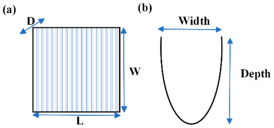
Figure 5.
Schematics of characterization and measurement: (a) micro-dimple; (b) groove.
In addition, in order to evaluate the quality of grooves and the machining accuracy of micro-structures on curved surfaces, the removal rate and the root mean square of the shape error were introduced as indicators of micro-structure and groove quality. The removal rate is defined as the ratio of the actual volume removed from the area where the cell is located on the surface of the workpiece to the theoretical volume removed from the cell design. The theoretical volume removed from the cell design refers to the target removal volume specified during the design phase, which serves as a reference benchmark. In this study, the actual removal volume of micro-structures under different methods is calculated from the measured values, and the removal volume of micro-structures under the plane is taken as the theoretical value. Then, the micro-structure removal rate is shown in Equation (1) [38]
where D, W, and L denote the depth, width, and length of the micro-pit structure under the plane, respectively, and the corresponding D0, W0, and L0 denote the depth, width, and length measurements under other methods. The value of γ in the formula indicates the removal rate, and the closer γ is to 1 represents that the processed micro-structure pattern is more accurate, and no distortion occurs.
The root mean square of the shape error is used to measure the degree of distortion of the micro-structure, as shown in Equation (2).
The smaller root mean square in Equation (2) represents the smaller degree of distortion of the processed micro-structure, which is more consistent with the theoretical value. The groove structure removal rate and root mean square can be given as shown in Equation (3), similarly [38].
3. Results and Discussion
3.1. Results of the Single-Factor Experiment on Grooving
Figure 6 demonstrates the change rule of groove depth and width with the number of scans, laser frequency, scanning speed, and single-pulse energy. A fixed laser frequency of 70 kHz, a scanning speed of 10 mm/s, a single-pulse energy of 10 μJ, and change the scanning speed. With the increase in the number of scans, the groove depth first rapidly increased before the scanning times of 30 and the growth rate slowed down after. The groove width do not show a significant increase with the increase in the number of scans Figure 6a. This is because with the increase in the number of times of processing, the laser pulse continues to act with the stainless steel surface, which produces ablation, resulting in a rapid increase in depth, and when the depth of the groove reaches a certain value, the laser pulse energy at the bottom of the groove will be attenuated, resulting in weakened ablation. The increase in the depth of the groove slows down, and the depth of the existence of a limit value can be predicted due to the laser pulse energy distribution being approximate to the Gaussian distribution, i.e., high in the middle and low at the edge. One of the reasons why groove widening is not observed within the processing times in this experiment is that the laser single-pulse energy is low, and although the number of processing times increases, the edge energy is not enough to produce significant ablation of stainless steel. Another possible reason is that the width has already reached the ablation limit for this energy level.
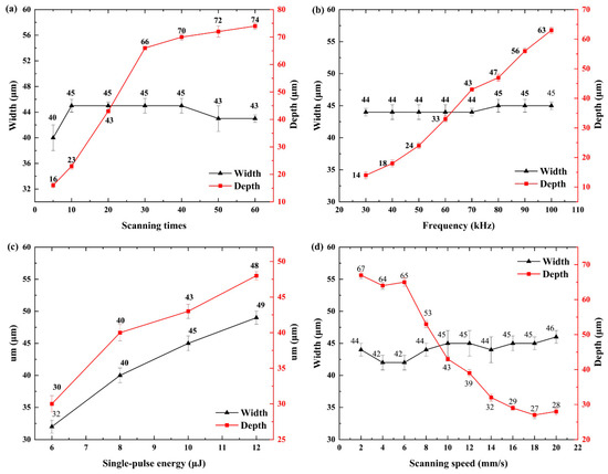
Figure 6.
Effect of laser parameters on groove depth and width: (a) scanning times; (b) frequency; (c) single-pulse energy; (d) scanning speed.
Figure 6c illustrates the relationship between groove depth and width and single-pulse energy (a laser frequency of 70 kHz, a scanning speed of 10 mm/s, 20 processing times). As the energy increases, both the groove depth and width expand. This is attributed to the rise in energy at the periphery of the laser spot, which is initially lower and increases and facilitates the material’s ablation threshold, reaching it more easily.
Figure 6b shows the variation of groove depth and width with laser frequency (a single-pulse energy of 10 μJ, a scanning speed of 10 mm/s, 20 processing times). As the laser frequency increases, the groove depth keeps increasing while the width remains at a relatively stable level. Figure 6d demonstrates the variation of groove depth and width with scanning speed (a single-pulse energy of 10 μJ, a laser frequency of 70 kHz, 20 processing times). With the increase in scanning speed, the groove depth shows a decreasing trend, while the groove width is maintained at a stable level. Laser frequency and scanning speed decide the spot overlap rate. The width of the groove depth that is needed to produce the impact of the spot overlap rate in the formula is shown in Equation (4) [39], where Sover is the spot overlap rate, Vscan is the scanning speed, frep is the laser pulse frequency, and df is the spot size. When the laser frequency increases or the scanning speed decreases, the spot overlap rate will increase, and the overlap rate will lead to an increase in the effective action time of the laser pulse at the same processing position, which will make the ablation phenomenon more obvious. So, the depth of the groove is increased, while the width remains relatively constant because a single pulse is not enough energy to produce significant ablation at the edges.
In order to better investigate the influence of the laser incidence angle on the groove molding law, we choose to further investigate the influence of the incidence angle on the groove morphology under the following laser parameter conditions: 10 μJ of single-pulse energy, a scanning speed of 10 mm/s, a laser frequency of 70 kHz, and 20 processing times. Figure 7a shows the effect of the incidence angle on the groove depth and width of the law, with the increase in the incidence angle and within a certain range of the depth and width to maintain a relatively stable level. When the incidence angle of more than 11°, it can be observed that the depth and width of the groove begin to have a significant decline. This is because when the angle change is not large, although the spot in the workpiece shape distortion has occurred, resulting in a change in the energy distribution, the degree of distortion is low. The energy distribution has changed but can still be more normal with the surface ablation of the stainless steel. When the incident angle exceeds a certain threshold, the spot aberration is larger, resulting in the energy distribution still being approximately in line with the Gaussian distribution, but the energy density will be reduced, resulting in a reduction in the ablation effect. Figure 7b–d show the morphology of the laser incidence angles of 0°, 10°, 14°, and 18° taken by a confocal microscope, respectively. The groove structure is uniform with no obvious heat-affected zone when the laser incidence angles are 0° and 10°, and there is an obvious heat-affected zone on the surface of the grooves when the laser incidence angles are 14° and 18°. This is due to the fact that the incident angle is too large, which results in a change in the shape of the light spot, from a circle to an elliptical, while the edge energy density is reduced, which cannot occur with the ablation of the stainless steel surface. Figure 7f shows the cross-section shape of the groove when the laser incidence angles are 0°, 10°, 14°, and 18°. When the incidence angle is 0°, the groove morphology is more symmetrical, approximately in line with the Gaussian distribution; when the incidence angle is 10°, it can be observed that the groove morphology appears to a certain extent tilted, but the overall width of the depth of the 0° angle is more consistent. When the angle of incidence is 14°, the groove morphology also appears to a certain extent tilted, and the depth is significantly reduced; when the angle of incidence is 14°, the groove shape also appears to a certain extent tilted, and the depth is significantly reduced. When the incidence angle is 14°, the groove shape is also tilted to some extent, and the depth decreases significantly; when the incidence angle is 18°, the groove shape is already different from 0°, and it can be approximated as a processing failure.
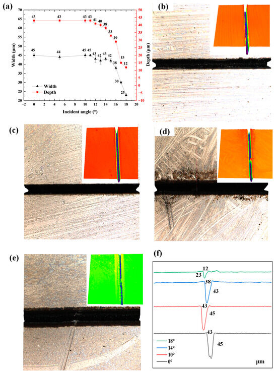
Figure 7.
Groove morphology results under varying incidence angles: (a) depth and width variation trends; (b) morphology at 0°; (c) morphology at 10°; (d) morphology at 14°; (e) morphology at 18°; (f) cross-sectional profiles at different incidence angles and their value of depth and width.
Figure 8 shows the changes in the removal rate and root mean square of the groove structure under different incidence angles, respectively. As shown in Figure 8a, with the increase in the incidence angle, the removal rate of the groove is the first to keep a stable level between 0.978 and 1, which indicates that the groove structure basically is the same as that of the grooves on the planar surface, and it starts to decrease gradually after the increase in the incidence angle up to 11 deg until it drops down to 0.143, which is the same as that of the groove depth and width with the incidence angle. This indicates that when the incidence angle continues to increase, the groove structure compared to the planar structure undergoes a significant distortion and loses the accuracy of the structure, which is the same as the change rule of the groove depth and width with the incidence angle. As shown in Figure 8b, with the increase in the incidence angle, the rms value of the groove is first maintained at a relatively small and stable level below 0.5 μm, which indicates that for 304L stainless steel, when the laser incidence angle is less than 11 degrees, the groove results show smaller aberrations and are closer to the dimensions of the planar grooves, and when the incidence angle is increased to 11 degrees, the rms value begins to rise gradually until it reaches 19 μm, which represents a larger dimensional distortion of the groove structure compared to the planar on-plane groove structure.
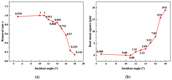
Figure 8.
Influence of varying incidence angles on the trench removal rate and root mean square effect: (a) removal rate; (b) root mean square.
3.2. Results of the Inclined Surface Micro-Dimples Experiment
Figure 9 illustrates the physical results of micro-dimple machining using a stainless steel flat plate simulating an inclined plane. Figure 9a shows the physical image of the micro-dimples processed at an inclination angle of 0 degrees, while Figure 9b,c show the physical images of the micro-dimples processed by the CGSP method and the direct projection method, respectively. Theoretically, the machining method proposed in this paper has less error in the structure and more closely resembles the machining situation on a flat surface compared to the direct projection method, but due to the limitation of the camera resolution and the surface reflection of the stainless steel material, the relevant differences are not easy to be distinguished by the naked eye. Specific differences will be shown in the microscopic images later on.
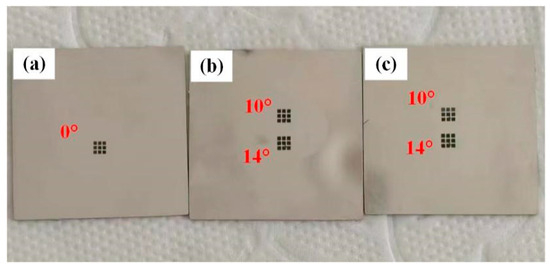
Figure 9.
Physical representation of micro-dimples on the inclined plane: (a) control; (b) DP; (c) CGSP.
Figure 10 presents the micro-dimple morphology obtained using different methods at various inclination angles. In Figure 10a–e, different colors represent different values of height. Figure 10b shows the micro-dimple morphology processed using the direct projection method when the planar inclination angle is 10°. Compared to the micro-dimples in Figure 10a at an inclination angle of 0°, the size of the micro-dimples is slightly enlarged. This enlargement occurs because the curvature of the surface causes a misalignment between the projection direction and the surface normal of the workpiece, resulting in greater distortion when using the direct projection method. Figure 10c presents the micro-dimples processed with the CGSP method under the same inclination angle condition. Compared to the direct projection method, the micro-dimples produced by the CGSP method are closer in size to those obtained at an inclination angle of 0°, indicating that the CGSP method is more effective in reducing distortion. Figure 10d,e depict the micro-structural morphology processed using the direct projection method and the CGSP method, respectively, at an inclination angle of 14°. It can be observed that the micro-dimples produced by the CGSP method more closely resemble the morphology of the planar micro-dimples. Figure 10f illustrates the cross-sectional shapes of micro-dimples obtained by different methods at various inclination angles. When the inclination angle is 0°, the width and depth of the micro-dimples are 424 μm and 71 μm, respectively. Compared to a single-line groove, the depth is greater because the scanning pitch of this structure is 20 μm, while the laser spot diameter is 45 μm. This results in overlapping scanning paths, leading to energy accumulation and an intensified ablation effect, making it easier to reach the ablation limit. The width of the micro-dimples processed using the direct projection method is significantly larger than that of the planar micro-dimples. This is because direct projection causes the actual laser scanning pitch to be greater than the theoretical design value, leading to an increased width. However, the depth does not decrease significantly since despite the increased laser scanning pitch, it does not exceed a critical threshold. As a result, the overlap ratio between scanning paths remains sufficient to prevent a sudden drop in energy density. In contrast, the width of the micro-dimples processed by the CGSP method is closer to that of the planar micro-dimples, further demonstrating its effectiveness in reducing micro-dimple deformation. When the inclination angle increases to 14°, the width and depth of the micro-dimples processed using the direct projection method are 447 μm and 60 μm, respectively, while those obtained using the CGSP method are 426 μm and 56 μm. This further verifies the effectiveness of the CGSP method in minimizing micro-dimple deformation. The reduction in depth is attributed to the incidence angle exceeding a certain threshold, which is consistent with the previously discussed trend in groove depth variation. The bottom of Figure 10a–e exhibits slight irregularities, which are caused by the scanning spacing used in the structural design.
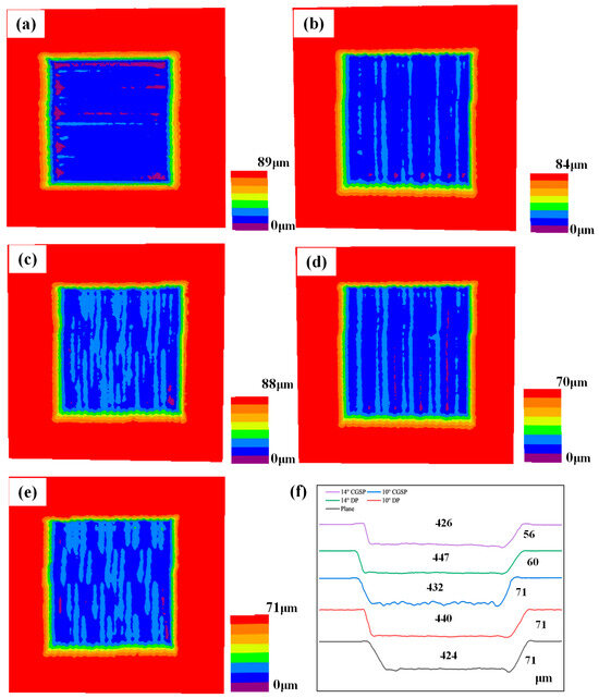
Figure 10.
Morphological results of the micro-dimples on an inclined plane: (a) planar control, (b) 10° DP, (c) 10° CGSP, (d) 14° DP, (e) 14° CGSP, (f) cross-sectional profiles of various methods at different angles and their depth and width. The color scale indicates that different colors correspond to varying heights, with the numerical values expressed in micrometers.
As shown in Figure 11, the removal rate and root mean square values obtained using different methods at various inclination angles are presented. When the inclination angle is 10°, the removal rate and RMS value obtained using the direct projection method are 1.043 and 7.071 μm, respectively, while those obtained using the CGSP method are 1.002 and 4.784 μm. This further indicates that the direct projection method induces deformation in both the micro-dimples and the pattern shape, leading to significant dimensional errors. In contrast, the CGSP method effectively reduces these errors. When the inclination angle increases to 14°, the removal rate and root mean square value obtained using the direct projection method are 0.847 and 9.894 μm, respectively, whereas the CGSP method yields 0.859 and 5.676 μm. This demonstrates that the CGSP method effectively minimizes micro-structural processing errors. However, the removal rate does not significantly approach 1, primarily due to the incidence angle exceeding a certain threshold, which limits the ablation capability. Furthermore, the oblique surface texturing experiment further confirms that the incidence angle should be restricted to within 11° to prevent increased processing errors.
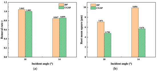
Figure 11.
Removal rates and root mean square values for various methods at different incidence angles: (a) removal rate; (b) root mean square.
3.3. Results of the Spherical Surface Micro-Dimples Experiment
As shown in Figure 12, the actual images of spherical surfaces processed using different methods at various positions are presented. Figure 12a shows the spherical surface processed using the CGSP method, while Figure 12b shows the spherical surface processed using the direct projection method. At position a, there is no significant difference in the micro-structural morphology obtained by the two methods. This is because within the localized central region of the sphere, the angle between the surface normal and the projection direction is relatively small, resulting in a minimal distortion from the direct projection method, which is difficult to detect with the naked eye. At position b, a significant shape deformation is clearly observed in the micro-dimples processed using the direct projection method. This occurs because at position b, the angle between the surface normal and the projection direction is much larger. However, after applying the CGSP method, the shape deformation is significantly reduced.
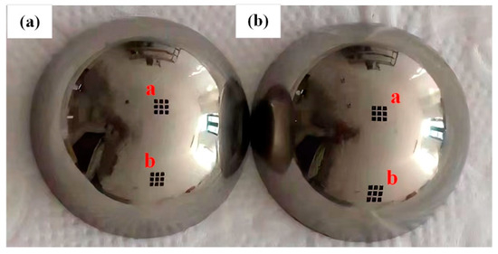
Figure 12.
Physical representation of micro-dimples on the spherical surface: (a) CGSP; (b) DP.
As shown in Figure 13, the microscopic morphology of different positions on the spherical surface processed using different methods is presented. In Figure 13a–e, different colors represent different values of height. Figure 10a, as a reference group, displays the microscopic morphology of planar micro-dimples. Figure 13c presents the morphology at position a on the spherical surface processed using the CGSP method. Compared to Figure 13b, where position a was processed using the direct projection method, the micro-dimples fabricated using the CGSP method exhibit dimensions that are more similar to those of planar micro-dimples. This demonstrates that the CGSP method is more effective in reducing distortion. Figure 13d shows the micro-dimple morphology at position b processed using the direct projection method, where significant shape deformation is evident. In contrast, Figure 13e shows that the micro-dimples produced using the CGSP method exhibit a more accurate pattern. Figure 13f presents the cross-sectional profiles of micro-dimples processed using different methods at different positions on the spherical surface. The width and depth of the planar micro-dimples are 424 μm and 71 μm, respectively, with a greater depth compared to single-line grooves. This is due to the scanning interval being 20 μm, while the laser spot diameter is 45 μm, leading to overlap between scanning paths. As a result, energy accumulation intensifies the ablation effect, making it easier to reach the ablation limit. At position a on the spherical surface, the width and depth of the micro-dimples processed using the direct projection method are 439 μm and 62 μm, respectively, while those processed using the CGSP method are 427 μm and 71 μm. The micro-dimples processed using the direct projection method exhibit a significantly larger width than planar micro-dimples. This is due to the direct projection causing the actual laser scanning interval to exceed the theoretical design value, leading to increased micro-dimple width. Meanwhile, the reduction in depth is attributed to the increased scanning interval, which lowers the overlap rate between scanning lines, consequently decreasing energy density and slightly reducing the ablation depth. Compared to the direct projection method, the CGSP method produces micro-dimples with widths closer to those of planar micro-dimples. This further confirms that the CGSP method effectively reduces micro-dimple deformation, making the structures more consistent with the intended design. The bottom of Figure 13a–e exhibits slight irregularities, which are caused by the scanning spacing used in the structural design. The surface irregularities observed in Figure 13b–e arise from height variations of the spherical surface, as measured by the confocal microscope. These variations, caused by inherent surface topography changes, do not influence the accuracy of the measurement results.
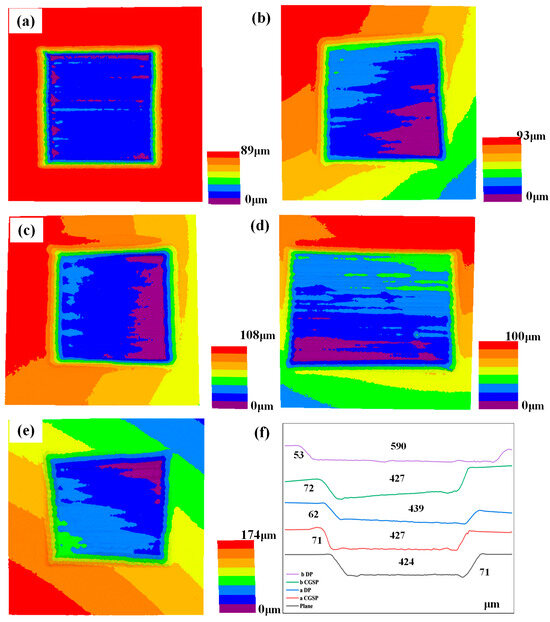
Figure 13.
Morphological results of micro-structures on the sphere: (a) planar control, (b) position a DP, (c) position a CGSP, (d) position b DP, (e) position b CGSP, (f) cross-sectional profiles of different methods at different positions and their depth and width. The color scale indicates that different colors correspond to varying heights, with the numerical values expressed in micrometers.
As shown in Figure 14, the removal rate and root mean square (RMS) values obtained using different methods at different positions on the spherical surface are presented. At position a on the spherical surface, the removal rate and RMS values for the direct projection method are 0.921 and 8.165 μm, respectively, whereas for the CGSP method, they are 0.988 and 3.559 μm. This further indicates that the direct projection method introduces micro-dimples and pattern shape distortions, resulting in significant dimensional errors, whereas the CGSP method effectively mitigates these errors. At position b on the spherical surface, the removal rate and RMS values for the direct projection method are 1.09 and 57.28 μm, respectively, while for the CGSP method, they are 0.936 and 13.601 μm. The removal rate of the direct projection method is closer to 1 compared to the CGSP method. This is attributed to the significant distortion in the ablation width at position b when using the direct projection method, which causes the calculated ablation volume to be closer to that of planar micro-dimples than the CGSP method. Overall, the analysis confirms that the CGSP method effectively reduces micro-dimple processing errors, making it more suitable for precisely processing micro-dimples on curved surfaces.
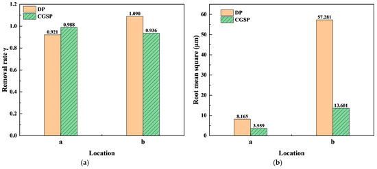
Figure 14.
Removal rates and root mean square values for various methods at different locations: (a) removal rate; (b) root mean square.
4. Conclusions
This study systematically explores the fabrication of laser micro-structures under non-perpendicular incidence conditions. The CGSP method was employed to successfully fabricate micro-pit textures on inclined and spherical surfaces, with accuracy assessed based on the removal rate and root mean square (RMS) values. The key findings are summarized as follows:
- (1)
- The effect of laser incidence angle on groove formation under non-perpendicular conditions was investigated. At a single-pulse energy of 10 µJ, a frequency of 70 kHz, a scanning speed of 10 mm/s, and 20 processing cycles, groove quality remains consistent across different angles when the incidence angle is below 11°.
- (2)
- The CGSP processing method was proposed and validated, with micro-dimples fabricated on inclined surfaces with tilt angles of 10° and 14°. Compared to the direct projection method, the CGSP method effectively reduces micro-structure deformation and distortion. Specifically, micro-structures fabricated using the CGSP method exhibit a removal rate closer to unity and reduced RMS values.
- (3)
- By combining the CGSP method with rotational processing, micro-dimples were successfully fabricated at various positions on a spherical surface. The removal rates of 0.988 and 0.936 were closer to unity than those achieved via direct projection, while the RMS values were reduced by 56.4% and 76.2%, respectively. The results confirm that within a specific range of incidence angles, the CGSP method enables the fabrication of micro-structures with higher precision.
This study has not yet extensively explored microscale mechanisms, which may impose limitations on future applications.
Author Contributions
Y.T.: formal analysis, data curation, methodology, and writing—original draft; Y.Z.: formal analysis, data curation, and methodology; Z.L.: formal analysis, data curation, and methodology; R.K.: formal analysis, data curation, and methodology; X.W.: conceptualization, resources, supervision, and writing—review and editing. All authors have read and agreed to the published version of the manuscript.
Funding
This work was funded by the Natural Science Foundation of Jiangsu Province [BK20231479]; Jiangsu Agriculture Science and Technology Innovation Fund (JASTIF) [CX(23)3030].
Institutional Review Board Statement
Not applicable.
Informed Consent Statement
Not applicable.
Data Availability Statement
Data is contained within the article.
Conflicts of Interest
The authors declare that they have no known competing financial interests or personal relationships that could have appeared to influence the work reported in this paper.
References
- Feng, X.; Guan, H.; Wang, Z.; Niu, S.; Han, Z. Biomimetic Slippery PDMS Film with Papillae-Like Microstructures for Antifogging and Self-Cleaning. Coatings 2021, 11, 238. [Google Scholar] [CrossRef]
- Liu, L.; Tang, W.; Ruan, Q.; Wu, Z.; Yang, C.; Cui, S.; Ma, Z.; Fu, R.K.Y.; Tian, X.; Wang, R.; et al. Robust and durable surperhydrophobic F-DLC coating for anti-icing in aircrafts engineering. Surf. Coat. Technol. 2020, 404, 126468. [Google Scholar] [CrossRef]
- Choi, Y.J.; Ko, J.H.; Jin, S.W.; An, H.S.; Kim, D.B.; Yoon, K.H.; Kim, H.W.; Chung, C.M. Transparent Self-Cleaning Coatings Based on Colorless Polyimide/Silica Sol Nanocomposite. Polymers 2021, 13, 4100. [Google Scholar] [CrossRef]
- Hao, C.; Wang, G.; Chen, C.; Xu, J.; Xu, C.; Kuang, H.; Xu, L. Circularly Polarized Light-Enabled Chiral Nanomaterials: From Fabrication to Application. Nanomicro Lett. 2023, 15, 39. [Google Scholar] [CrossRef] [PubMed]
- Soukoulis, C.M.; Kafesaki, M.; Economou, E.N. Negative-Index Materials: New Frontiers in Optics. Adv. Mater. 2006, 18, 1941–1952. [Google Scholar] [CrossRef]
- Wang, J.; Sun, H.; Zhao, R.; Zhang, X.; Liu, H.; Wei, C. Three-dimensional microflowers assembled by carbon-encapsulated-SnS nanosheets for superior Li-ion storage performance. J. Alloys Compd. 2018, 767, 361–367. [Google Scholar] [CrossRef]
- Zhang, L.; Chen, H.; Guo, Y.; Wang, Y.; Jiang, Y.; Zhang, D.; Ma, L.; Luo, J.; Jiang, L. Micro-Nano Hierarchical Structure Enhanced Strong Wet Friction Surface Inspired by Tree Frogs. Adv. Sci. 2020, 7, 2001125. [Google Scholar] [CrossRef]
- Pan, X.; Zhou, L.; Hu, D.; He, W.; Liu, P.; Yu, Z.; Liang, X. Superior wear resistance in cast aluminum alloy via femtosecond laser induced periodic surface structures and surface hardening layer. Appl. Surf. Sci. 2023, 636, 157866. [Google Scholar] [CrossRef]
- Rajan, R.A.; Rao Konda, S.; Sajed Saraj, C.; Hang Lai, Y.; Verma, G.; Yu, Z.; Yu, W.; Yan, D.; Yang, J. Long-term seawater anti-corrosion properties of Al alloy triggered by femtosecond laser structuring with phase change. Appl. Surf. Sci. 2022, 573, 151612. [Google Scholar] [CrossRef]
- Kedia, S.; Bonagani, S.K.; Majumdar, A.G.; Kain, V.; Subramanian, M.; Maiti, N.; Nilaya, J.P. Nanosecond laser surface texturing of type 316L stainless steel for contact guidance of bone cells and superior corrosion resistance. Colloid Interface Sci. Commun. 2021, 42, 100419. [Google Scholar] [CrossRef]
- Balázs, B.Z.; Geier, N.; Takács, M.; Davim, J.P. A review on micro-milling: Recent advances and future trends. Int. J. Adv. Manuf. Technol. 2021, 112, 655–684. [Google Scholar] [CrossRef]
- Zahedinejad, M.; Khaje, M.; Erfanian, A.; Raissi, F.; Mehrara, H.; Rezvani, F. Patterning of porous silicon nanostructures and eliminating microcracks on silicon nitride mask using metal assisted chemical etching. Thin Solid Film. 2012, 520, 2080–2084. [Google Scholar] [CrossRef]
- Le Borgne, B.; Jacques, E.; Harnois, M. The Use of a Water Soluble Flexible Substrate to Embed Electronics in Additively Manufactured Objects: From Tattoo to Water Transfer Printed Electronics. Micromachines 2018, 9, 474. [Google Scholar] [CrossRef]
- Knoll, M.; Offenzeller, C.; Jakoby, B.; Hilber, W. Screen printed sensors fabricated on non-planar surfaces by water transfer print. Microelectron. Eng. 2019, 209, 49–52. [Google Scholar] [CrossRef]
- Porenta, N.; Nydegger, M.; Menétrey, M.; Hammadi, S.; Reiser, A.; Spolenak, R. Micron-scale additive manufacturing of binary and ternary alloys by electrohydrodynamic redox 3D printing. Mater. Des. 2023, 234, 112364. [Google Scholar] [CrossRef]
- Jin, K.; Zhang, N.; Wang, W.; Hao, Y.; Liu, B. 2D compound structures with deep subwavelength period on silicon fabricated by double time delayed femtosecond laser beams. Photonics Nanostruct. Fundam. Appl. 2023, 57, 101188. [Google Scholar] [CrossRef]
- She, L.; Qi, Q.; Zhang, P.; Dai, S.; Jiang, Y.; Sun, W.; Jia, S.; Wang, S.; Brambilla, G.; Wang, P. Mid-infrared fluoroindate glass long-period fiber grating by femtosecond laser inscription. Infrared Phys. Technol. 2021, 116, 103808. [Google Scholar] [CrossRef]
- He, W.; Yao, P.; Chu, D.; Sun, H.; Lai, Q.; Wang, Q.; Wang, P.; Qu, S.; Huang, C. Controllable hydrophilic titanium surface with micro-protrusion or micro-groove processed by femtosecond laser direct writing. Opt. Laser Technol. 2022, 152, 108082. [Google Scholar] [CrossRef]
- Duan, L.; Zhou, H.; Duan, J.-a. Micro-groove manufacturing via a femtosecond laser on optically clear adhesive films. Appl. Surf. Sci. 2022, 604, 154439. [Google Scholar] [CrossRef]
- Gu, Z.; He, Y.; Yang, J.; Fu, Y.; Ji, J.; Zhang, Y.; Li, J.; Liu, G. Dual-path micro-holes process for 0Cr17Ni7Al stainless steel thin plate with picosecond laser. J. Manuf. Process. 2023, 101, 1224–1233. [Google Scholar] [CrossRef]
- Zhang, N.; Wang, M.; Ban, M.; Guo, L.; Liu, W. Femtosecond laser drilling 100 μm diameter micro holes with aspect ratios > 20 in a Nickel based superalloy. J. Mater. Res. Technol. 2024, 28, 1415–1422. [Google Scholar] [CrossRef]
- Liu, Y.; Li, X.; Jin, J.; Liu, J.; Yan, Y.; Han, Z.; Ren, L. Anti-icing property of bio-inspired micro-structure superhydrophobic surfaces and heat transfer model. Appl. Surf. Sci. 2017, 400, 498–505. [Google Scholar] [CrossRef]
- Patel, D.S.; Singh, A.; Balani, K.; Ramkumar, J. Topographical effects of laser surface texturing on various time-dependent wetting regimes in Ti6Al4V. Surf. Coat. Technol. 2018, 349, 816–829. [Google Scholar] [CrossRef]
- Yilbas, B.S.; Keles, O.; Toprakli, A.Y. Surface Engineering towards Self-Cleaning Applications: Laser Textured Silicon Surface. Procedia Eng. 2017, 184, 716–724. [Google Scholar] [CrossRef]
- Kruse, C.M.; Anderson, T.; Wilson, C.; Zuhlke, C.; Alexander, D.; Gogos, G.; Ndao, S. Enhanced pool-boiling heat transfer and critical heat flux on femtosecond laser processed stainless steel surfaces. Int. J. Heat Mass Transfer 2015, 82, 109–116. [Google Scholar] [CrossRef]
- Rajab, F.H.; Liauw, C.M.; Benson, P.S.; Li, L.; Whitehead, K.A. Production of hybrid macro/micro/nano surface structures on Ti6Al4V surfaces by picosecond laser surface texturing and their antifouling characteristics. Colloids Surf. B Biointerfaces 2017, 160, 688–696. [Google Scholar] [CrossRef]
- Wang, H.; Deng, D.; Zhai, Z.; Yao, Y. Laser-processed functional surface structures for multi-functional applications—A review. J. Manuf. Process. 2024, 116, 247–283. [Google Scholar] [CrossRef]
- Baimler, I.V.; Simakin, A.V.; Dorokhov, A.S.; Gudkov, S.V. Mini-review on laser-induced nanoparticle heating and melting. Front. Chem. 2024, 12, 1463612. [Google Scholar] [CrossRef]
- Jj Nivas, J.; Allahyari, E.; Skoulas, E.; Bruzzese, R.; Fittipaldi, R.; Tsibidis, G.D.; Stratakis, E.; Amoruso, S. Incident angle influence on ripples and grooves produced by femtosecond laser irradiation of silicon. Appl. Surf. Sci. 2021, 570, 151150. [Google Scholar] [CrossRef]
- Lu, Y.; Deng, J.; Wang, R.; Wu, J.; Meng, Y. Tribological performance of micro textured surface machined by Nd:YAG laser with different incident angle. Opt. Laser Technol. 2022, 148, 107768. [Google Scholar] [CrossRef]
- Wang, X.; Duan, J.; Jiang, M.; Ke, S.; Wu, B.; Zeng, X. Study of laser precision ablating texture patterns on large-scale freeform surface. Int. J. Adv. Manuf. Technol. 2017, 92, 4571–4581. [Google Scholar] [CrossRef]
- Haker, S.; Angenent, S.; Tannenbaum, A.; Kikinis, R.; Sapiro, G.; Halle, M. Conformal surface parameterization for texture mapping. IEEE Trans. Vis. Comput. Graph. 2000, 6, 181–189. [Google Scholar] [CrossRef]
- Alla, S.; Emil, P.; Kenneth, R. Mesh Parameterization Methods and Their Applications; Now Foundations and Trends: Boston, MA, USA, 2006; pp. 12–35. [Google Scholar]
- Guo, J.; Liu, G.; Zhang, G.; Guan, Y.; Zhang, H. Projection algorithm for 3D laser marking. In Proceedings of the 2015 IEEE International Conference on Robotics and Biomimetics (ROBIO), Zhuhai, China, 6–9 December 2015; pp. 2199–2204. [Google Scholar]
- Luo, R.C.; Tseng, P.K. Carving 2D image onto 3D curved surface using hybrid additive and subtractive 3D printing process. In Proceedings of the 2017 International Conference on Advanced Robotics and Intelligent Systems (ARIS), Taipei, Taiwan, 6–8 September 2017; pp. 40–45. [Google Scholar] [CrossRef]
- Xiao, H.; Zhou, Y.; Liu, M.-j.; Zhang, W. Approach to optimize STL model for 3D laser machining. DEStech Trans. Comput. Sci. Eng. 2017, 16369. [Google Scholar] [CrossRef] [PubMed]
- Jiang, M.; Wang, X.; Ke, S.; Zhang, F.; Zeng, X. Large scale layering laser surface texturing system based on high speed optical scanners and gantry machine tool. Robot. Comput. Integr. Manuf. 2017, 48, 113–120. [Google Scholar] [CrossRef]
- Jian, W.; Kaiyu, J.; Ao, Q.; Huabin, L.; Ji, Z. Experimental Study of Laser Etching of Non-DevelopableSurface Functional Structures. J. Air Force Eng. Univ. 2024, 25, 22–27. [Google Scholar] [CrossRef]
- Dong, Y.; Shao, P.; Guo, X.; Liu, S.; Zhu, X.; Guo, W. Experimental study on the effect of laser overlap rate on the quality of femtosecond laser machining of micro-holes. Opt. Laser Technol. 2024, 177, 111205. [Google Scholar] [CrossRef]
Disclaimer/Publisher’s Note: The statements, opinions and data contained in all publications are solely those of the individual author(s) and contributor(s) and not of MDPI and/or the editor(s). MDPI and/or the editor(s) disclaim responsibility for any injury to people or property resulting from any ideas, methods, instructions or products referred to in the content. |
© 2025 by the authors. Licensee MDPI, Basel, Switzerland. This article is an open access article distributed under the terms and conditions of the Creative Commons Attribution (CC BY) license (https://creativecommons.org/licenses/by/4.0/).