1. Introduction
Nowadays, bainitic steels are increasingly used in industry for the production of mechanical components, such as shafts and gears, due to their ability to suppress carbide formation, which can lead to steel brittleness, and their favorable combination of mechanical and functional properties. Submicron and nanobainitic steels thus represent materials with significant application potential [
1,
2,
3,
4,
5,
6]. For certain applications, such as the deposition of hard, wear-resistant coatings (e.g., CVD coatings), it is necessary to achieve a surface hardness exceeding that of the base bainitic steel to improve the coating’s resistance to spalling under load [
7,
8,
9]. In this context, the use of surface hardening methods becomes essential, particularly for components in gearboxes, where the durability of the gear teeth directly affects the reliability of the entire system.
The most commonly employed surface hardening techniques are electron beam hardening (EBH) and laser beam hardening (LBH). Compared to conventional thermal treatments, laser beam hardening offers enhanced precision for components with complex geometries. The process features a minimal heat-affected zone and limited thermal distortion, which often reduces or eliminates the need for post-processing. The high heating and cooling rates enable the formation of a fine-grained, hard surface structure, and precision beam deflection systems allow processing of components with intricate geometries [
10,
11,
12,
13,
14,
15,
16]. EBH exhibits higher energy efficiency and a greater power reserve, enabling the formation of hardened layers ranging from a few micrometers to several millimeters in thickness. The process is unaffected by plasma phenomena or beam reflection, and the vacuum environment prevents surface oxidation, which is particularly important for precision gears. Moreover, dynamic beam deflection at frequencies up to 1 kHz allows selective hardening of specific surface areas without moving the component [
9,
17,
18,
19,
20].
Combining the properties of bainitic steels with advanced EBH or LBH techniques results in surfaces with unique mechanical and functional characteristics, which are crucial for extending the service life and reliability of gears in industrial applications. Both methods are widely employed in industry, and the literature consistently confirms their effectiveness in improving the performance of transmission components.
One such example of EBH treatment is the research conducted by the Production Engineering Department at Isuzu Motors Ltd. on the application of electron hardening technology in the automotive industry [
21], which demonstrated the high efficiency of this method and paved the way for its wider industry application. The material utilized for the experimental investigations was 34CrMo4 steel. The research methodology entailed local heating of the sample using only an oscillating electron beam. Utilizing the established parameters, it was observed that the maximum depth of hardening achieved without the occurrence of a liquid phase was 0.9 mm.
Results of the EBH process were also studied in the publication [
22], authored by Song R.G. et al., which presents the findings of a study on the effects of electron beam hardening of AISI D3 tool steel. The outcome of this study is the attainment of surface layers with a depth of approximately 400 μm with the highest hardness of the surface layer measured at approximately 1400 HV0.1. The hardness of the base material was found to be 650 HV 0.1. Another research study undertaken by Jie Y. et al. [
23] presents the results of a hardening process of 40CrMn steel using an oscillating electron beam. The hardening process consisted of three parallel passes at different values of overlap. The surface treatment resulted in an increase in hardness to approximately 650 HV, with the initial hardness of the native material being 300 HV. The phenomenon of tempering has been observed due to the interaction between thermal cycles of successive passes, which caused a decrease in hardness in the tempered zone even to a value of about 400 HV. The research conducted by Deqiang W. [
24] and his team demonstrated that, in comparison with the initial state, the surface microhardness exhibited a significant enhancement. The maximum hardness obtained was 656 HV, while the hardness of the native material was 355 HV.
A plethora of articles have been published on the subject of optimizing the electron hardening process. In the paper presented by Matlák J. and Dlouhý I. [
25], the effects of using different beam deflection modes on the properties of electron beam-hardened layers were studied. The authors concluded that deflection patterns that are field-deflected in the direction parallel to the direction of motion, rather than only a line deflected in the perpendicular direction, result in an increase in the achieved hardening depth at the same sample speed movement rate. The research conducted by Petrov P. [
26], who presented the results of the optimization of the electron beam hardening process, demonstrated that the heating and cooling rates, as well as the overall efficiency of the electron beam hardening process, increased with the movement speed of the specimen. The article of Friedel K.P. et al. [
27] expounds research conducted on the optimization of the electron hardening process. The findings from both mathematical simulations and experimental studies demonstrated that the cooling rate and, consequently, the surface hardness were primarily influenced by the resulting electron beam power, while the hardening depth depended on the energy density of the electron beam on the surface of the hardened object. However, as demonstrated in the aforementioned article [
26], when the analyzed parameter is also the process speed, it exerts a decisive influence on the cooling speed.
Among the published scientific papers, many works on the laser hardening process can be found. Article [
28] describes research into optimizing overlap sizes in multi-stitch laser hardening of large surfaces or rotating elements. Research shows that the distance between axes of the stitches must be less than the effective hardening width. 42CrMo4 steel was used to reproduce all the conditions and a hardness comparison was carried out, showing a good degree of compliance. The team of Anusha E. et al. [
29] developed a laser hardening method for rotating components without tempering effects using a high-speed manipulator. This quasi-stationary technique facilitates a uniform hardened layer over the workpiece’s entire surface, eliminating tempering effects in overlapping areas. The model’s validity was confirmed through experiments using a 4 mm square laser spot on a 12 mm thick cylindrical En-31 steel bar. Optimal parameters resulted in a hardened layer across the entire machined layer. In the work of C. Yao et al. [
30], steel grades 45, 9Cr2Mo, and W18Cr4V were hardened using multi-shot laser hardening, resulting in tempering in each grade. The hardness test results showed that the tempering zone width varied according to steel grade. Different mixed microstructures formed the overlap zone for each steel. The influence of carbon diffusion activation energy in steel and cooling rate on martensite decomposition was investigated. The results show that carbon diffusion activation energy plays a key role in counteracting carbide decomposition and cooling rate has a limited effect on tempering during laser scanning. Philipp Schüßler et al. [
13] presented a simulative study of tempering mechanisms on hardness and residual stress. This resulted in a local hardness lower than the base material due to self-tempering effects. The study also showed that the modeling of tempering mechanisms during laser surface hardening enhances prediction of hardness and stress. It facilitates optimization of the process.
The work of Mahmoud Moradi et al. [
31] presents the findings of an experimental study on laser surface hardening of AISI 410 stainless steel. It used two industrial lasers to explore the effects of various laser parameters on surface hardening. The study investigated the influence of laser distribution and shape, focusing on top-hat and Gaussian beams. The parameters measured included microhardness, geometrical dimensions, microhardness deviation, and ferrite phase percentage. Optical and FE-SEM methodologies were used to evaluate the microstructure of the hardened zones. The findings showed that the diode laser generates higher hardness and reduced ferrite phase. This is due to its lower wavelength (808 nm) relative to the Nd:YAG laser (1064 nm), enhancing laser energy absorption. The diode laser hardened layer was 620 HV0.3 with a depth of 1.8 mm, while the Nd:YAG layer was 598 HV0.3 with 0.21 mm depth. Carlos Soriano’s team [
32] investigated the surface hardening process of the 42CrMo4 steel alloy using an oscillating laser beam. The study utilized a high-power diode laser and a scanning mirror to examine the effect of oscillation frequency on temperature, geometry, microstructure, microhardness, and stress. The findings show that oscillating laser beams can harden surfaces more effectively than fixed optical guidance systems. The selected oscillation frequency significantly impacts the treated region, affecting temperature, geometry, microstructure, and stress. A high oscillation frequency is crucial for stability and uniformity.
Both of these methods have many industrial applications with LBH technology being used more frequently. Laser hardening usually finds its applications in manufacturing parts for automotive, railway, and aerospace industries such as cylinder liners, valve seats, camshafts, rocker arms, and gear teeth, as well as hardened zones on rails and wheel flanges for extended service life. This method is also used in manufacturing of tools, for example, in agricultural machinery or mining tools to harden blades, tines, plowshares or picks, hammers, and wear plates. Electron beam hardening usually has similar applications. It is widely used for hardening camshafts, crankshafts, gear wheels, splines, valves, turbine blades and rotors, injection molding dies, and tooling, as well as nuclear and high-vacuum components [
17,
18,
19,
20,
21].
While both methods aim to increase surface hardness and wear resistance, EBH is typically used in high-precision and vacuum-compatible applications, and it can be used to harden only the selected parts of workpieces due to its ability to deflect the beam very quickly into any shape. The high vacuum also provides significantly better metallurgical protection, making this method more suitable for hardening sensitive materials. Greater efficiency and higher power ratings allow thicker hardened layers to be achieved. On the other hand, LBH is used for processing parts with relatively simple geometry, especially when the entire surface is to be hardened. It can be used for hardening large parts because it is not limited by the size of the working chamber. It offers more accessible integration into production lines [
17,
18,
19,
20,
21].
The extant literature attests to the beneficial impact of electron and laser beam hardening methods on the properties of components subjected to such treatment. A substantial body of knowledge has accumulated regarding the optimization of these processes and the influence of individual parameters. However, a direct comparison between these two methods and the impact of electron and laser beam surface hardening on submicron bainitic steels remains to be elucidated. This paper presents the results of EBH and LBH processes of submicron bainitic steel in relation to the microstructure, phase composition, residual stresses, and hardness.
This study methodically compares two hardening methods, utilizing disparate parameters, and examining the effects on the macro- and microstructure of the resulting hardened layers and their resulting hardness. This study constitutes a significant addition to the extant technical and scientific knowledge concerning both the electron and laser beam hardening processes as a novel method to increase the surface layer hardness of submicron bainitic structured steels coating performance. A key aspect of this work is the innovative application of EBH technology to gears made of carbon-free bainitic steel, which is expected to significantly enhance the durability, fatigue resistance, and operational performance of gear teeth. This approach represents a new technological solution in the high-performance production of gear transmission components.
2. Materials and Methods
The research program includes following experiments:
- •
Electron beam hardening tests;
- •
Laser beam hardening tests;
- •
Light microscopy analysis of hardened layer geometry and microstructure;
- •
Scanning electron microscopy (SEM) microstructure analysis;
- •
Hardness testing;
- •
X-ray diffraction phase composition and residual stress analysis.
The material that was subjected to the treatment was steel, with the chemical composition of the material illustrated in
Table 1. The chemical composition was examined using a Magellan Q8 Optical Emission Spectrometer with spark excitation from Bruker Elemental GmbH, Ettlingen, Germany. Both the flat surface samples and the gear wheel come from the same casting.
The material in the form of cylinders was subjected to heat treatment to obtain a bainitic microstructure. Samples were austenitized at 900 °C for 30 min and then austempered for 120 min at a temperature 365 °C, which is slightly above the Ms temperature. Both stages of heat treatment were realized in an industrial vacuum furnace (Seco/Warwick 15VPT, SECO/WARWICK S.A., Świebodzin, Poland). The employment of an advanced heat treatment enabled a substantial reduction in the processing time and temperature, thereby facilitating the formation of a carbide-free bainite structure. In addition to reducing the time and temperature, the treatment resulted in an enhancement in the steel’s tensile strength, ductility, fracture toughness, and wear resistance compared to conventional quenching and tempering [
33].
After heat treatment, the cylinders were cut. The gear wheel intended for testing and blocks measuring 150 × 30 × 22 mm were milled from the original cylindrical shape. The hardened surface on the flat samples thus had dimensions of 150 × 30 mm.
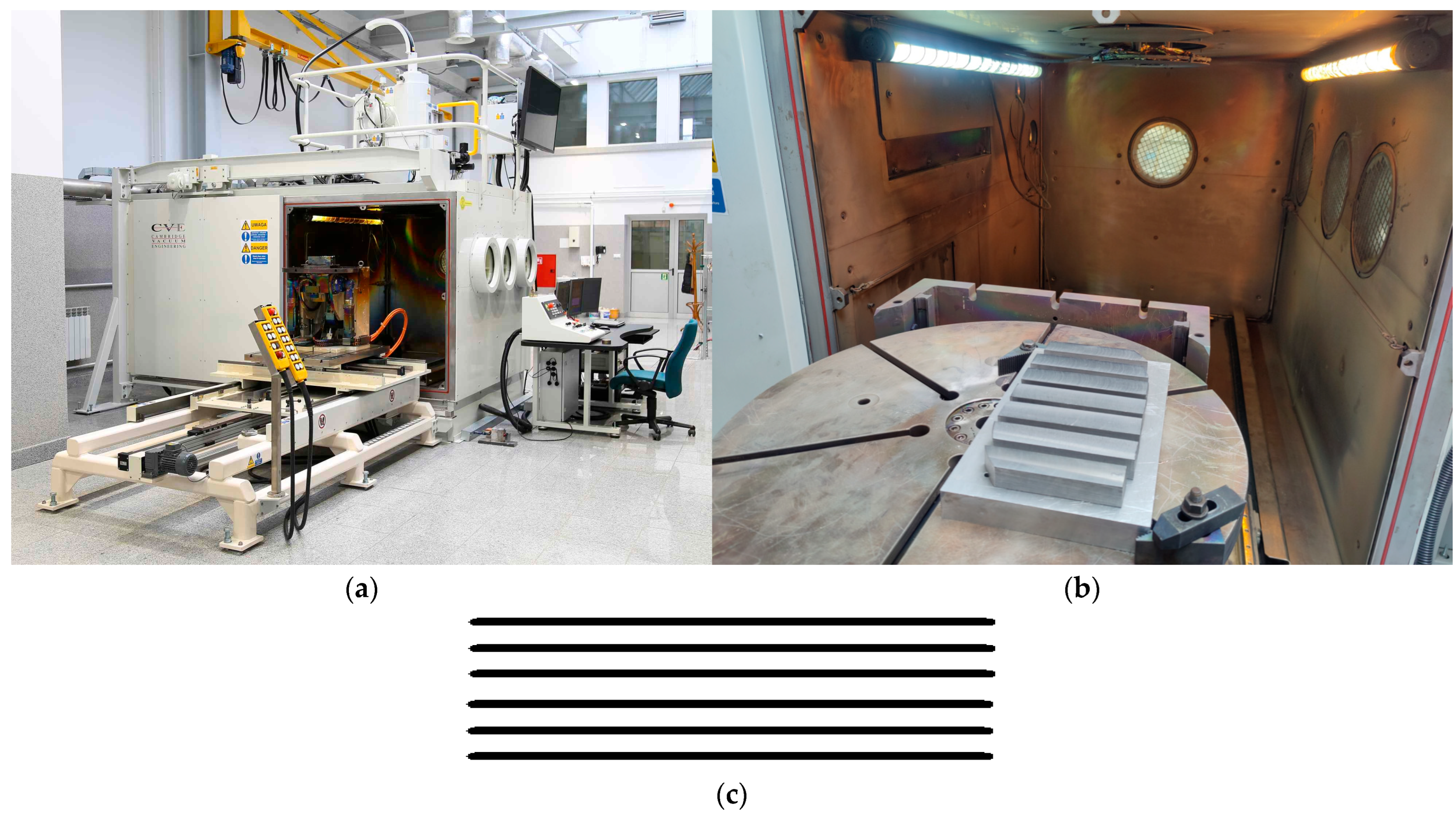
Samples were electron-beam-hardened using an electron beam welding machine from Cambridge Vacuum Engineering, Cambridge, UK, model XW150:30 (
Figure 1a), having a directly heated tungsten cathode filament, with a maximum accelerating voltage of 150 kV, a maximum current of 200 mA, and a working chamber of 2200 × 1500 × 1500 mm.
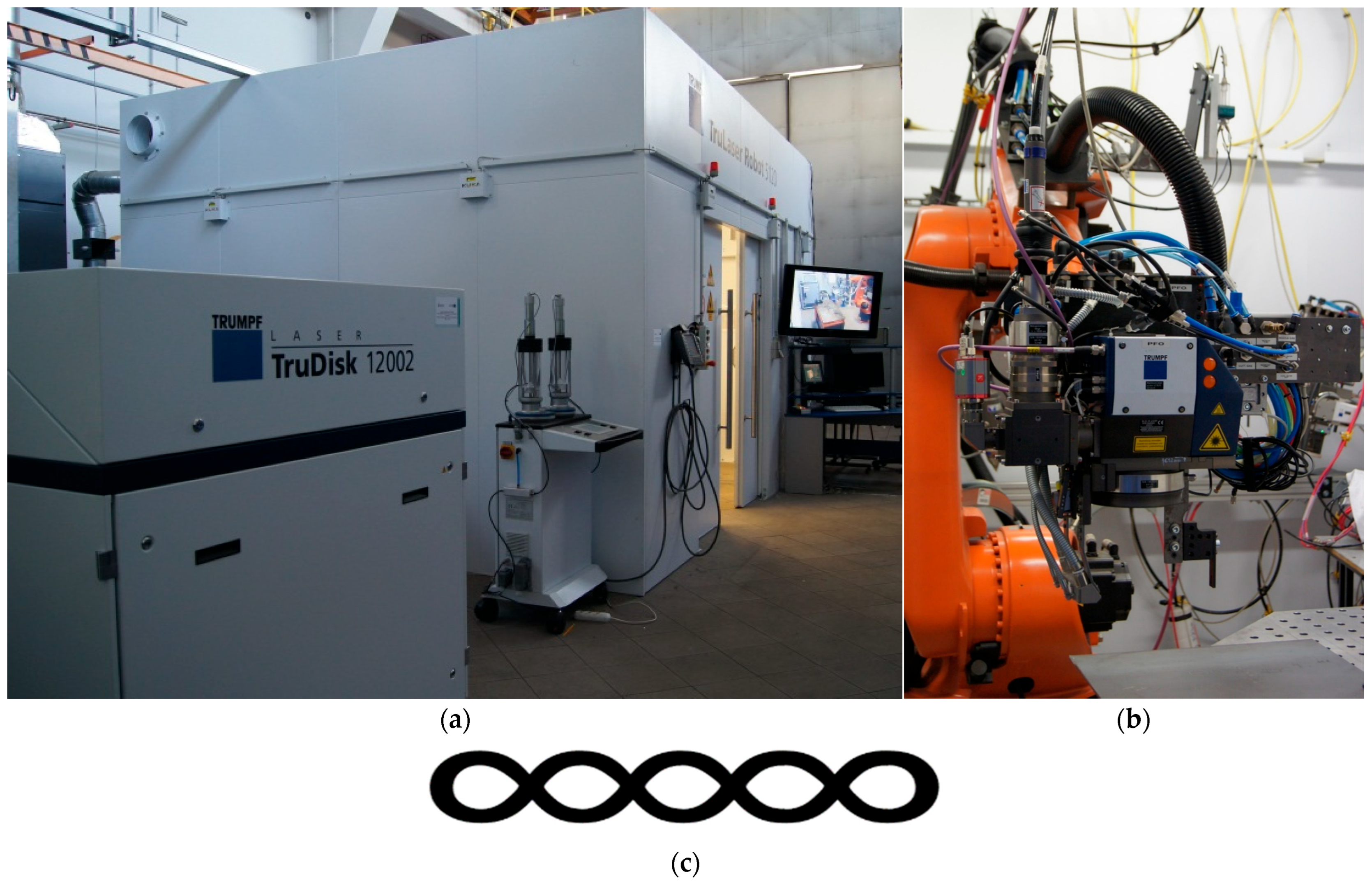
Technological trials of laser surface hardening were conducted on a robotic workstation equipped with a 12 kW TruDisk 12002 YAG disk laser from TRUMPF Laser GmbH, Ditzingen, Germany (
Figure 2a), a KUKA KR30HA industrial robot from KUKA Robotics GmbH, Augsburg, Germany and a PFO scanning head from RUMPF SE + Co. KG, Ditzingen, Germany (
Figure 2b). For the PFO head, the same optical fiber was used, but the focal length of the collimator lens was 200 mm and the focusing lens was 450 mm. Thus, a laser beam focusing area of 0.9 mm in diameter was obtained.
In light of the observations pertaining to the tempering of the hardened layer during the multi-pass electron beam hardening process [
23], it was determined that the entirety of the surface should be hardened in a single pass for both employed technologies. To be able to provide this in both cases, an oscillating beam with an amplitude of 30 mm was used in the direction perpendicular to the direction of sample movement. The analysis of process optimization literature work led to the conclusion that the specimen travel speed should be limited to a maximum of 2000 mm/min. A series of tests were conducted at speeds of 2000, 1500, 1000, 500, 250, and 100 mm/min. These tests demonstrated that at speeds exceeding 500 mm/min, it was not feasible to obtain a hardened layer greater than 1 mm without the formation of a liquid phase. This was a stipulated requirement of the project within which this research was conducted. During these tests, different shapes and longitudinal amplitudes of oscillations were used. For both technologies, a shape was chosen to ensure that the hardened layer was the most uniform in thickness.
During preliminary technological tests of electron hardening, it was noticed that samples after surface hardening cool very slowly due to the low heat capacity of the hardened element and the lack of additional cooling (e.g., by convection). This made it impossible to achieve a sufficiently high level of hardness in the hardened layer. This necessitated attachment of the samples to a 300 × 200 × 30 mm aluminum block via bolts (
Figure 1b). This procedure was intended to increase the heat capacity of the hardened specimen, thereby facilitating enhanced heat dissipation from the hardened surface. The fixture and the attached samples were mounted on the CNC table of an electron beam welding machine.
The electron beam hardening parameters were as follows:
- •
Accelerating voltage: 140 kV;
- •
Beam current: 35 mA (total output power of 4900 W);
- •
Pressure in the working chamber: 1 × 10⁻⁴ mbar;
- •
Working distance: 420 mm;
- •
Sample traveling speed (hardening speed): 500 mm/min.
The electron beam was defocused, with a current of 610 mA being delivered to the focusing lens. The focusing point for a distance of 420 mm was obtained at a current value of 710 mA. The specimen was subjected to a heating field with dimensions of 30 × 6 mm consisting of 6 parallel lines (
Figure 1c), oscillating at 200 Hz, while the sample was moved relative to the heating field.
The laser beam hardening parameters were as follows:
- •
Total output power of 7000 W;
- •
Shielding gas: argon (10 L/min);
- •
Working head linear traveling speed (hardening speed): 400 mm/min.
Technological tests of surface hardening were carried out using a defocused beam. The degree of defocusing was determined by the parameter f denoting the distance of the processing plane from the laser beam focus plane which was 250 mm. The specimen was subjected to a heating field with dimensions of 30 × 1 mm consisting of an infinity sign duplicated five times (
Figure 2c), oscillating at the speed of 1000 mm/s.
After thorough testing of the effects of electron hardening and their comparison with effects of laser beam hardening, additional tests of electron beam hardening were carried out on hardening a gear wheel with a tooth height of 25 mm intended for use in the transmission of a mining scraper conveyor.
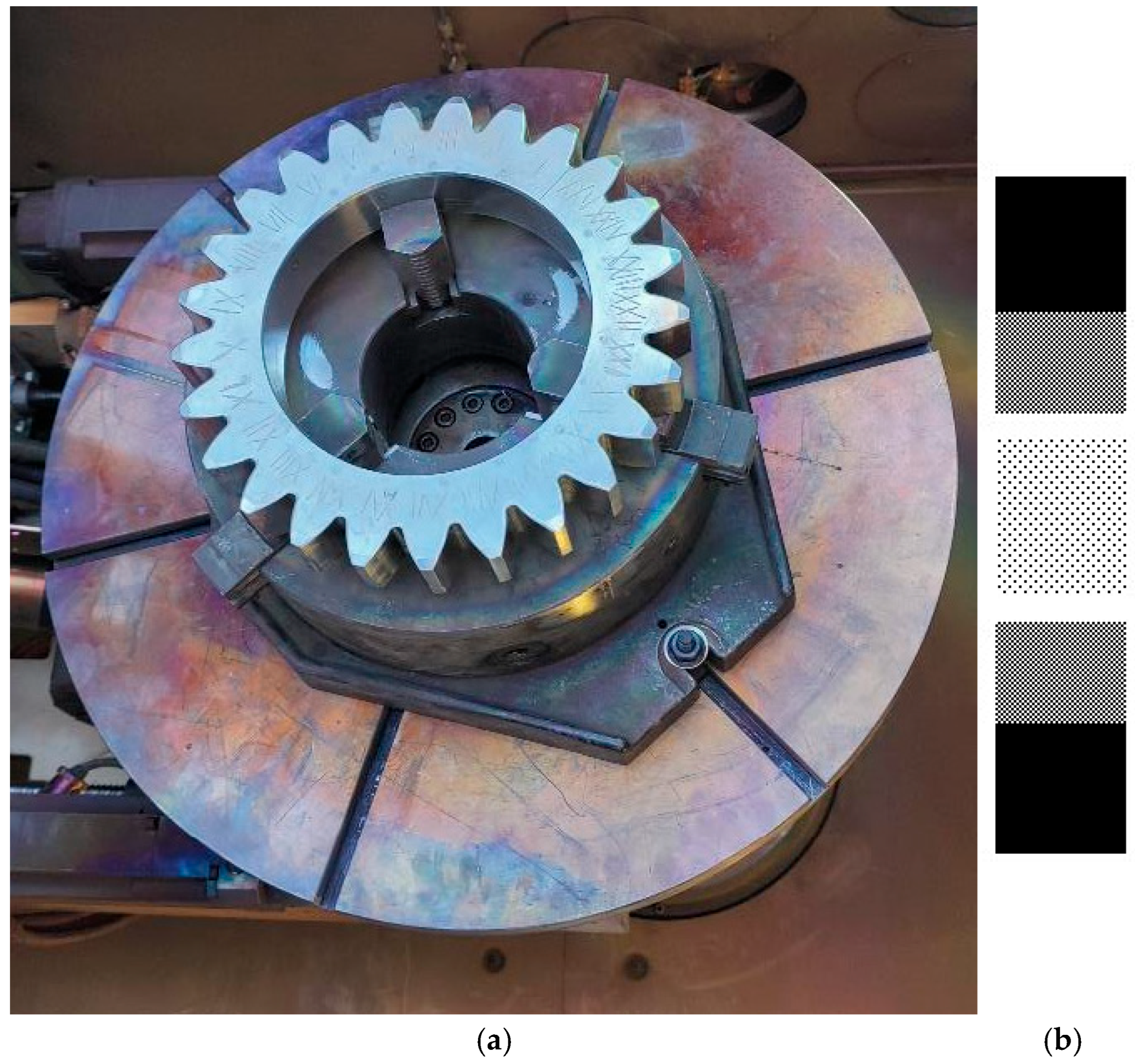
Figure 3a shows the gear mounted to the CNC table of the electron beam machine.
To evenly harden the entire tooth surface in a single pass, the control software functionality was used to convert a monochrome bitmap into a control function for the electromagnetic coils of the electron gun. The oscillatory pattern used in the form of a bitmap was developed on the basis of FEM simulations and technological tests. This pattern is shown in
Figure 3b. The gear tooths were hardened using the same accelerating voltage, pressure in the working chamber, and working distance. The current of the focusing lenses was also 610 mA. The difference, apart from the oscillatory pattern, was the movement speed (100 mm/min) and the beam current intensity (24 mA).
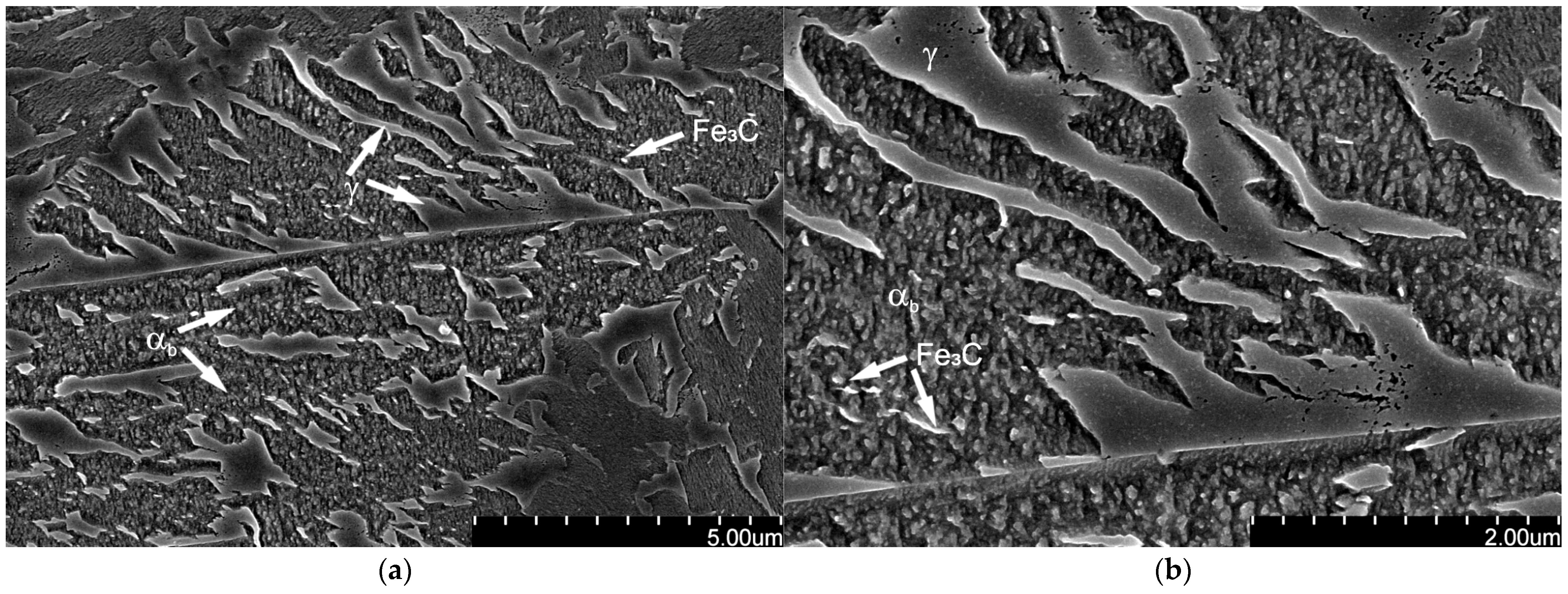
All the samples were meticulously prepared for observation by cutting across the long side, followed by cold mounting and grinding. This process was undertaken to ensure the acquisition of a suitable surface for microscopic analysis. The samples were then etched in 3% nital and then subjected to microscopic observations on a Nikon Eclipse MA200 light microscope from Nikon Corporation, Tokyo, Japan. Detailed SEM observations of the hardened layer were made using a Hitachi SU8000 microscope from Hitachi High‑Tech Corporation, Tokyo, Japan at the cross-sections of the samples at various thicknesses of the layer—near the surface, in the transition zone, and in the tempered zone. Observations were carried out using SE mode.
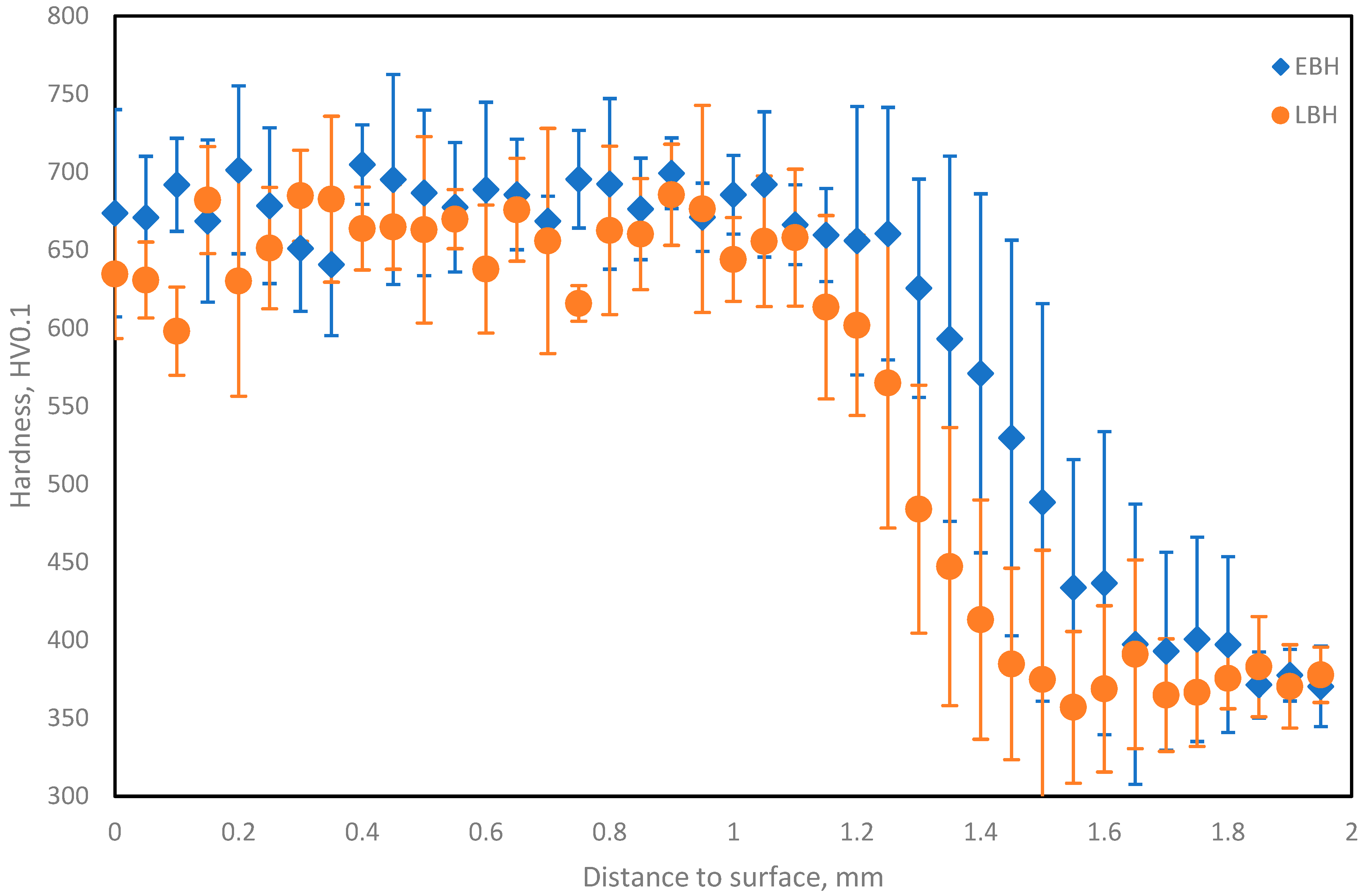
Following metallographic examination, the samples were submitted for hardness testing using an automatic hardness tester manufactured by KB Prüftechnik GmbH, Hochdorf-Assenheim, Germany. Hardness measurements were obtained at HV0.1 load. The measurements were taken in 50-micrometer increments. For the hardened layers, five measurement lines perpendicular to the hardened surface were made on each specimen. Each measurement line consisted of 40 points. The measurements were made in the cross-section of the test specimens. There was one additional measurement line parallel to the hardened surface at the distance of 5 mm of it, consisting of 100 points—to determine the hardness of the base material. Subsequent to this, the average hardnesses along with the standard deviations and maximum and minimum measured hardness values for all samples were calculated: for hardened layers—from 100 points in total, located at most 1 mm from the surface of the sample; for base material—from 100 points in the additional measurement line for the base material.
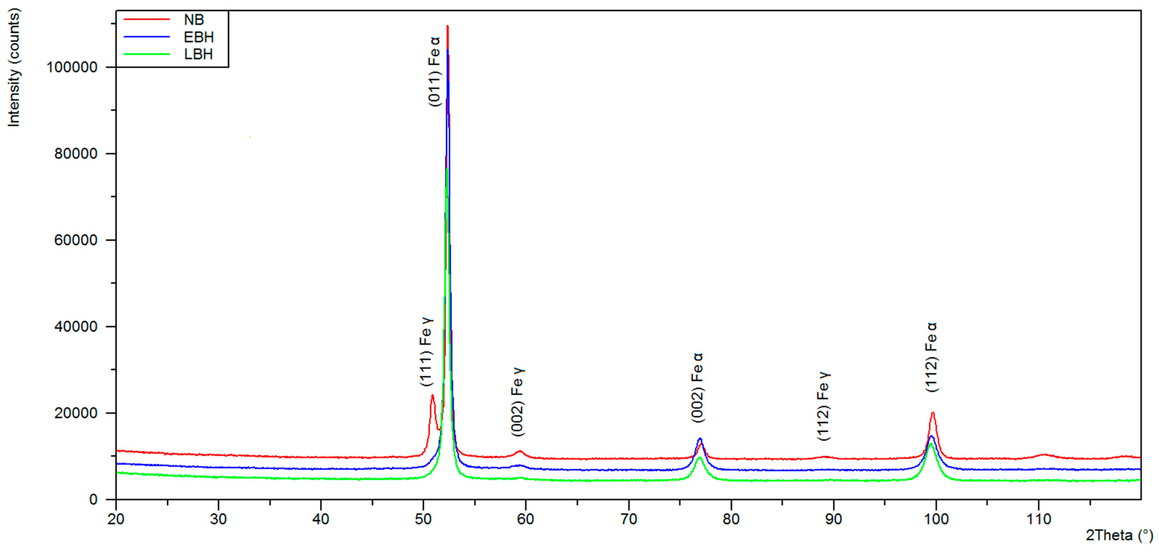
Phase composition studies were performed in an X’Pert PRO MPD X-ray diffractometer from PANalytical B.V., Almelo, The Netherlands, equipped with a cobalt anode X-ray tube (λKα = 0.179 nm) and a PIXcel 3D detector from PANalytical B.V., Almelo, The Netherlands on the deflected beam axis. Diffractograms were recorded in Bragg–Brentano geometry in the 20–120° 2 Theta angle range with a step of 0.05° and a counting time per step of 100 s. X-ray qualitative phase analysis was performed using HighScore Plus software (v. 3.0e) and the PAN-ICSD dedicated database of inorganic crystal structures. The quantitative proportions of the identified phases were calculated using the Rietveld method.
Tribocorrosion tests using the Ball-on-Disk method were also performed for both samples to simulate the real operating conditions of gears, which are characterized by the simultaneous presence of solid contaminants and saline mine water. The sandstone under investigation consisted mainly of quartz (59.26%) and, in smaller quantities, feldspar (7.64%), mica (biotite) and muscovite (9.87% in total). During the test, the sample was immersed in a mixture of a 3.5% NaCl aqueous solution and sandstone powder. In addition, there were rock fragments and heavy minerals (3.48%). The binder accounted for 19.75% of the rock’s volume and consisted of chalcedony (8.64%), carbonate minerals (6.17%), and clay minerals (4.94%).
The following test parameters were used:
- •
Sliding motion at an angle of 70°;
- •
Radius of 7.5 mm;
- •
12,000 cycles;
- •
Test duration of 2 h;
- •
Load of 10 N;
- •
Tungsten carbide ball with a diameter of 6 mm;
- •
Amount of substance: 12.4 g of sandstone per 40 mL of 3.5% NaCl solution.
4. Discussion
As shown in
Figure 4, both of the hardening methods used in this work gave similar results in terms of the layer thickness with a slightly higher (around 0.2 mm) value obtained for EBH. This is true even though the laser power was higher and the laser hardening speed was lower, which translates into a lower linear energy of the EBH process, which is 0.588 kJ/mm compared to the linear energy of the LBH process, which is 1.051 kJ/mm. The laser beam, depending on the wavelength and treated material, is subject to the phenomenon of reflection of part of the radiation. In the case of an electron beam, part of the beam may also be scattered or, e.g., participate in the emission of X-ray radiation, but the energy losses are much smaller than in the case of a laser beam. It seems evident that, in this specific instance of hardening, the efficiency of the laser process is considerably diminished, which confirms the conclusions of the analysis cited in the introduction [
28]. The resulting hardened surface thickness obtained with the EBH method was also more even than that obtained with the LBH method.
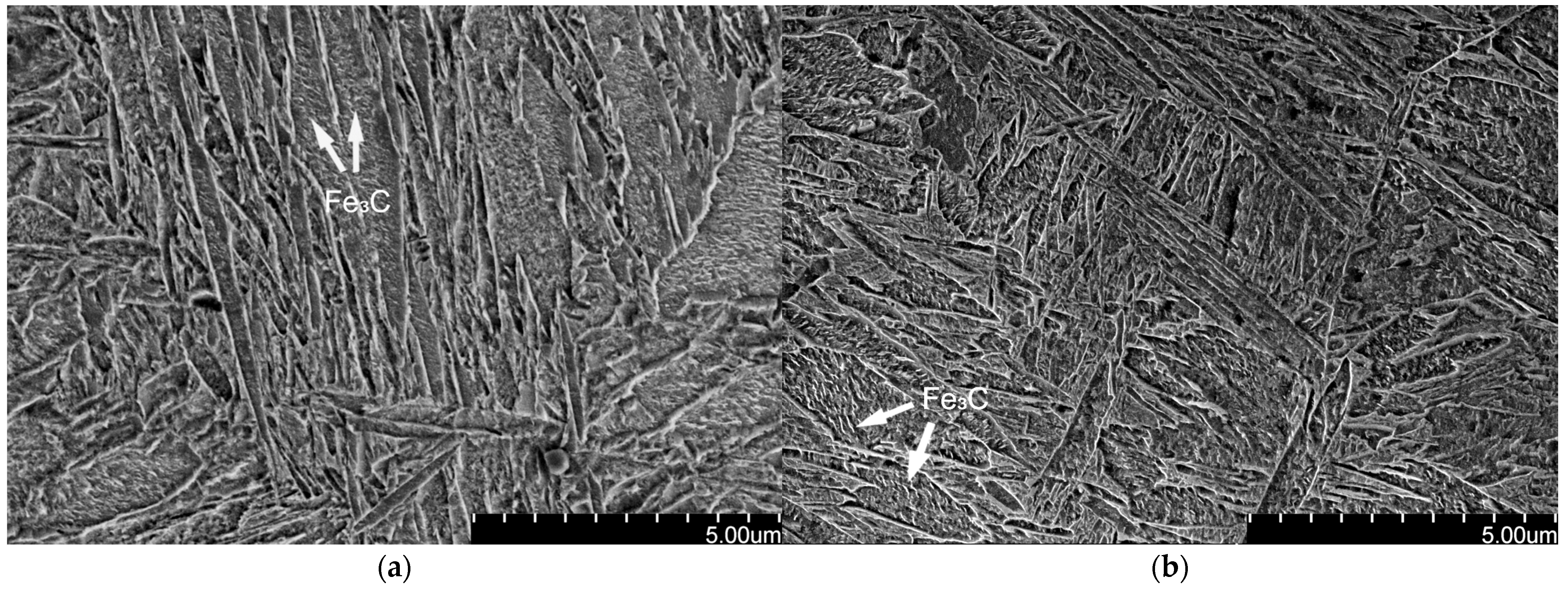
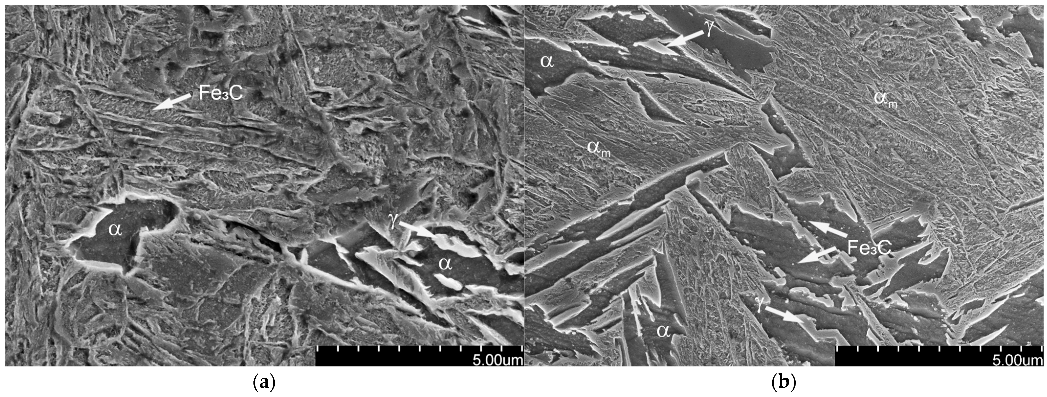
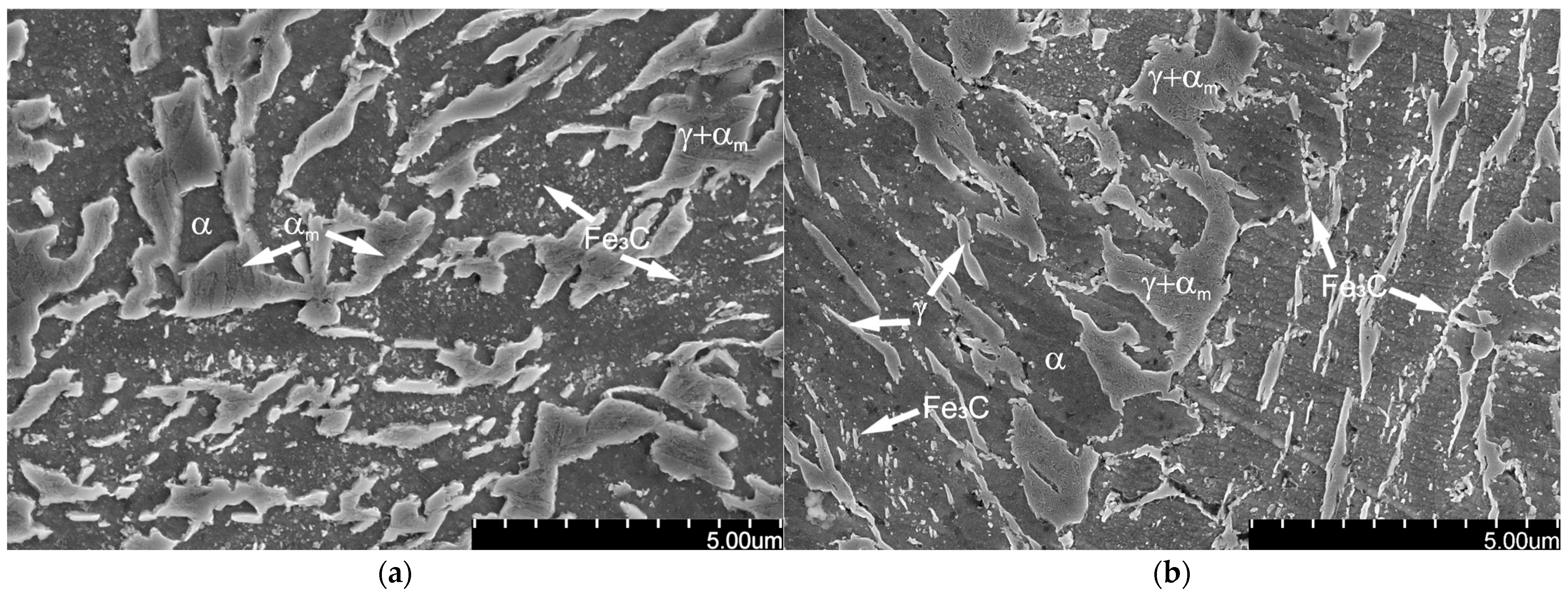
The microstructure in the surface zone of the layers produced by both methods did not differ significantly. However, in the transition zone, clear differences can be observed between layers hardened by different methods. In the EBH sample, the layer is thicker and ferrite appears at a much greater depth. The first ferritic areas in the LBH sample appear at a much shallower depth and are much more numerous. Additionally, the amount of auto-tempered martensite is greater in the LBH sample. Laser hardening was carried out in the atmosphere; thus, cooling rates during the process should be higher, resulting in shorter exposure to elevated temperatures and limited diffusion processes and carbide precipitation—carbon diffuses from martensite to austenite and stabilizes it without carbide precipitation. At the same time, the beam travel speed is lower, resulting in a longer stay at high temperature. Extending the time of exposure to temperature can cause carbides to precipitate in martensite, as a result of which the remaining austenite, due to a stress reduction, can undergo further transformations. On the other hand, EBH is a process carried out in a vacuum, which means that heat should be dissipated much more slowly due to the lack of convection in the chamber atmosphere. Therefore, to increase the rate of heat dissipation during EBH, samples were attached to an aluminum heat sink. This means that the heat generated during EBH penetrates to a greater depth, and at the same time, the material itself is exposed to heat for a shorter time.
For this reason, it is also evident that disparities in microstructure manifest within the tempered zone. In the EBH sample, a structure, characterized by the presence of few precipitates within the ferrite grains, was observed. In case of the LBH sample, the structure containing austenite layers between the ferrite plates was partially preserved, but a feathery structure was also observed. In this case, the precipitates were identified within the tempered zone, not only within the ferrite grains but also at the boundaries between ferrite and austenite, as well as at the boundaries of the former austenite. These precipitates have the potential to substantially diminish the strength and ductility within this area. Observed differences in the microstructure of hardened layers—significantly less autotempered martensite and fewer carbide precipitates—indicate the effectiveness of the aluminum heat sink as a means of accelerating cooling and the higher energy efficiency of EBH. From the point of view of the properties of the hardened layer, it is particularly important to limit carbide precipitation at the grain boundaries.
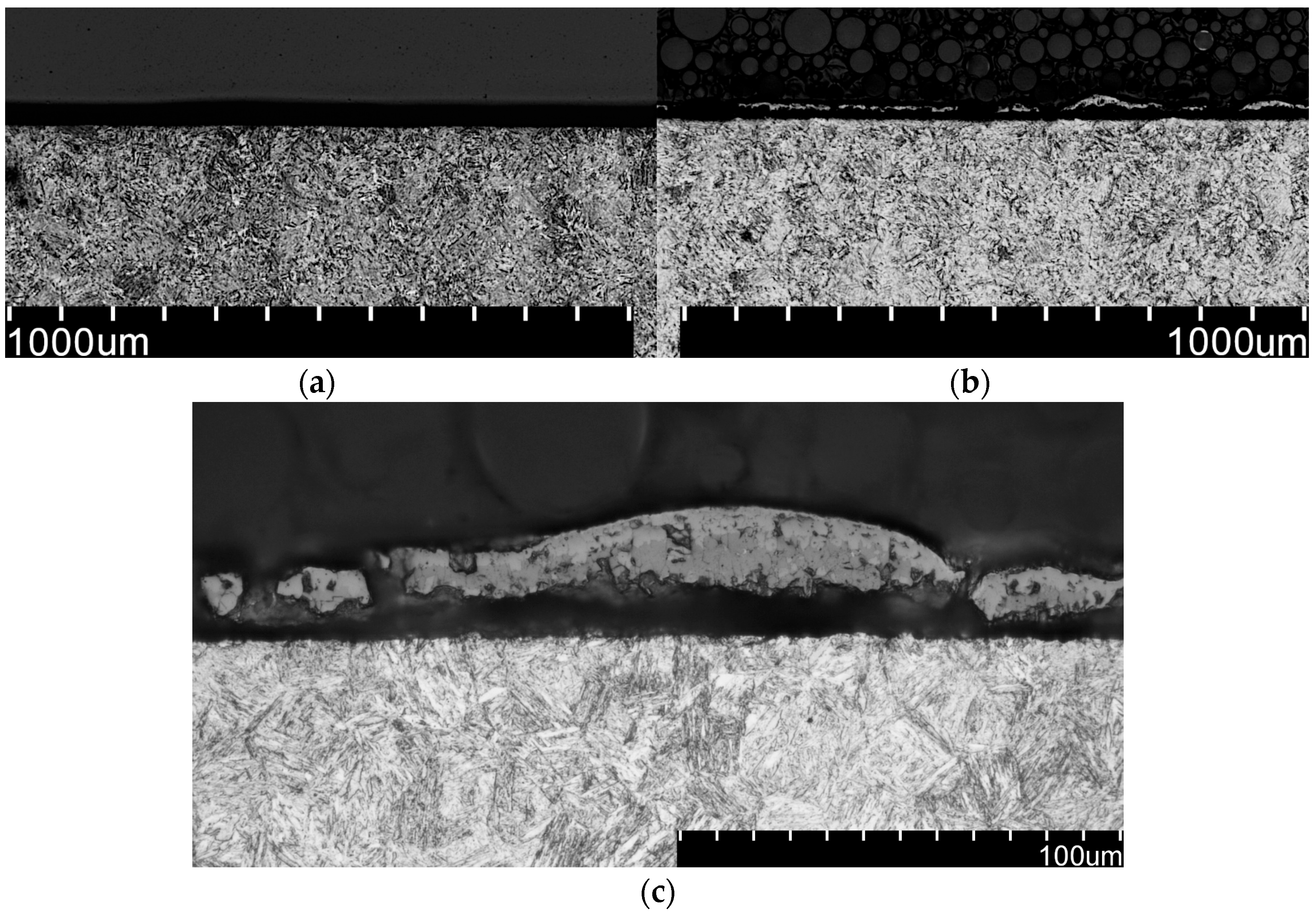
The layer visible in
Figure 6b,c forms due to insufficient shielding from oxygen in atmosphere during hardening, which also confirms the conclusions of the analysis cited in the introduction [
28]. A solution to this problem would be LBH with additional shielding or in the chamber filled with neutral gas or a vacuum chamber like the EBH process. Due to the oxide layer formation, the LBH sample surface should be cleaned prior to any coating application. This additional step makes the LBH process more inconvenient as a method for surface hardening of elements that will be coated using CVD or any other coating method.
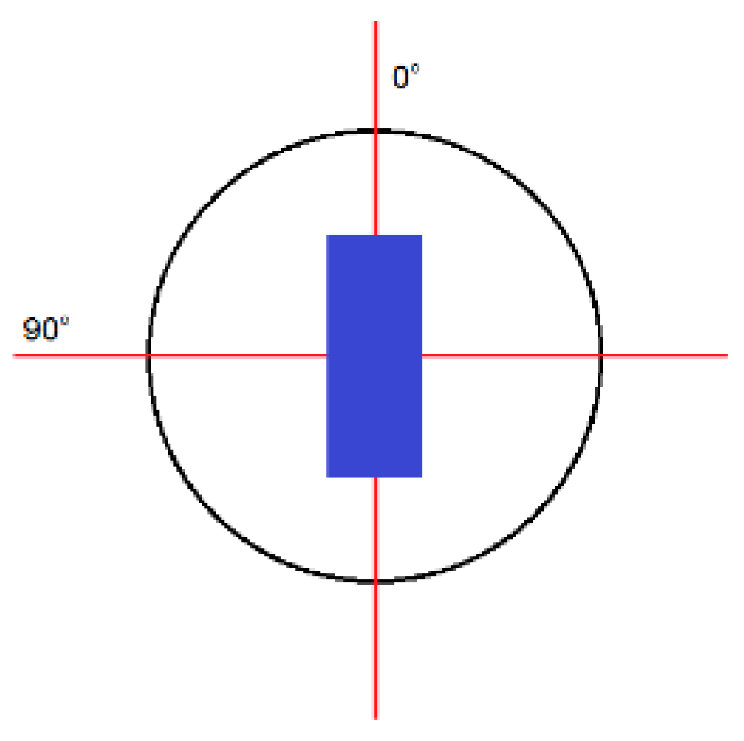
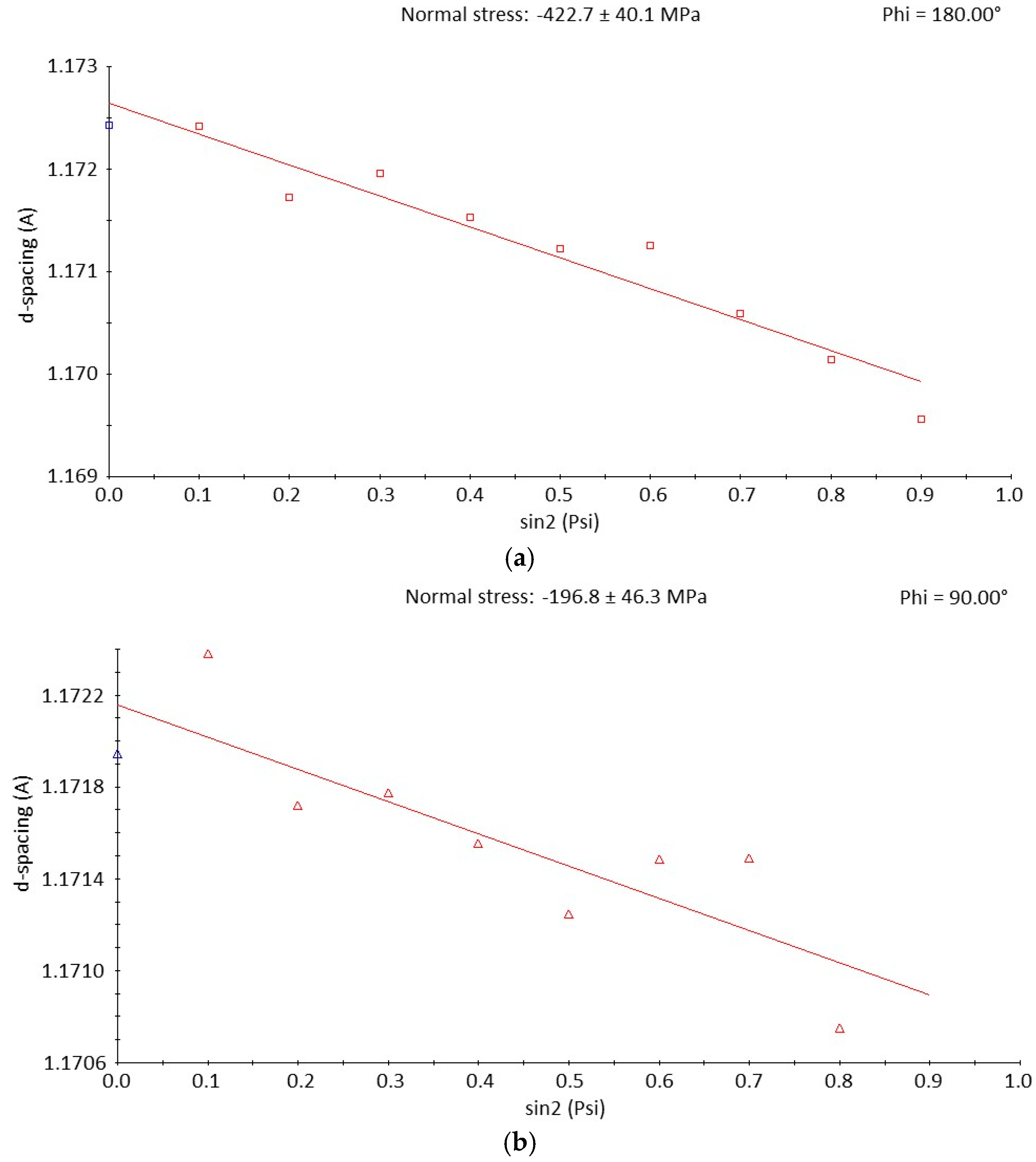
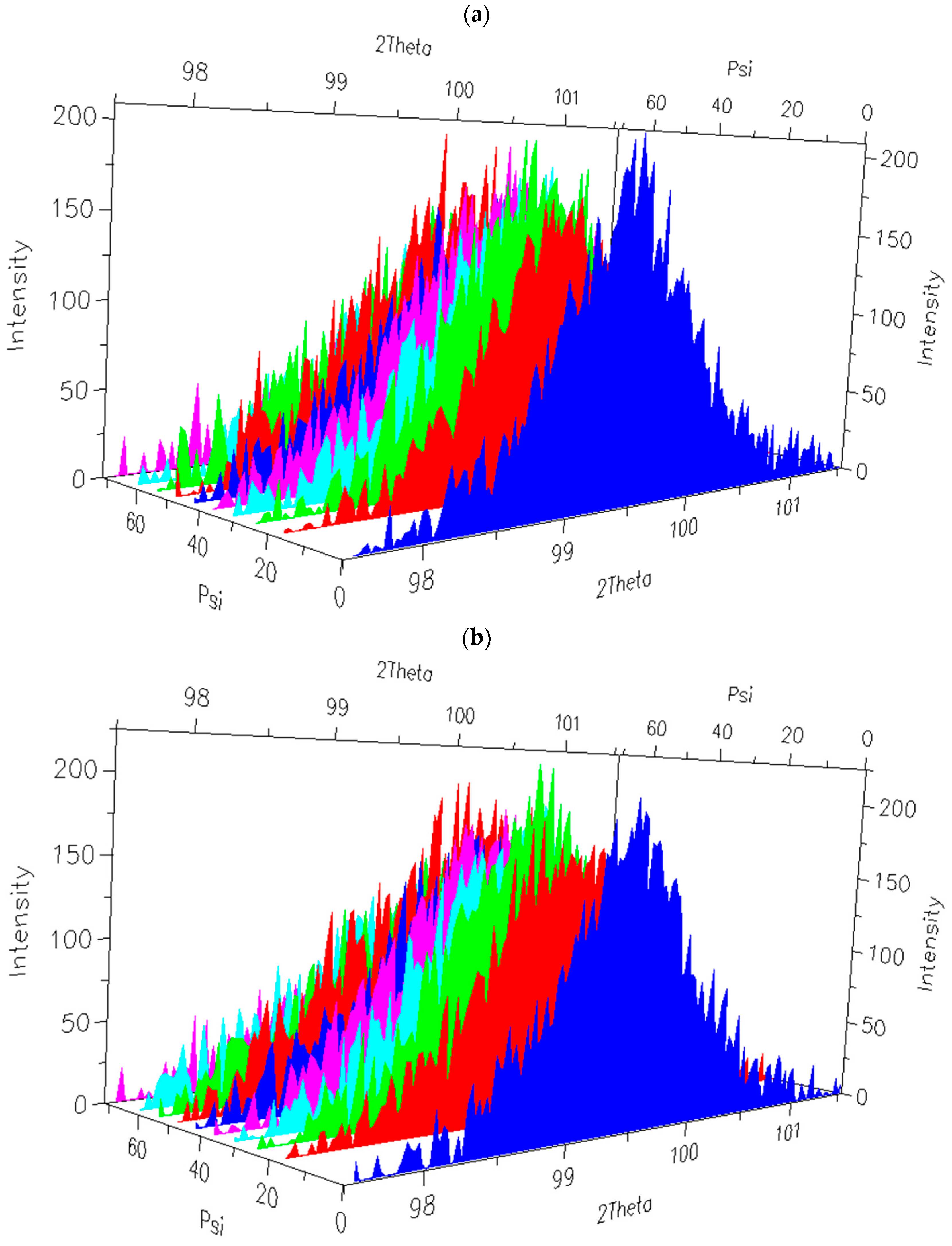
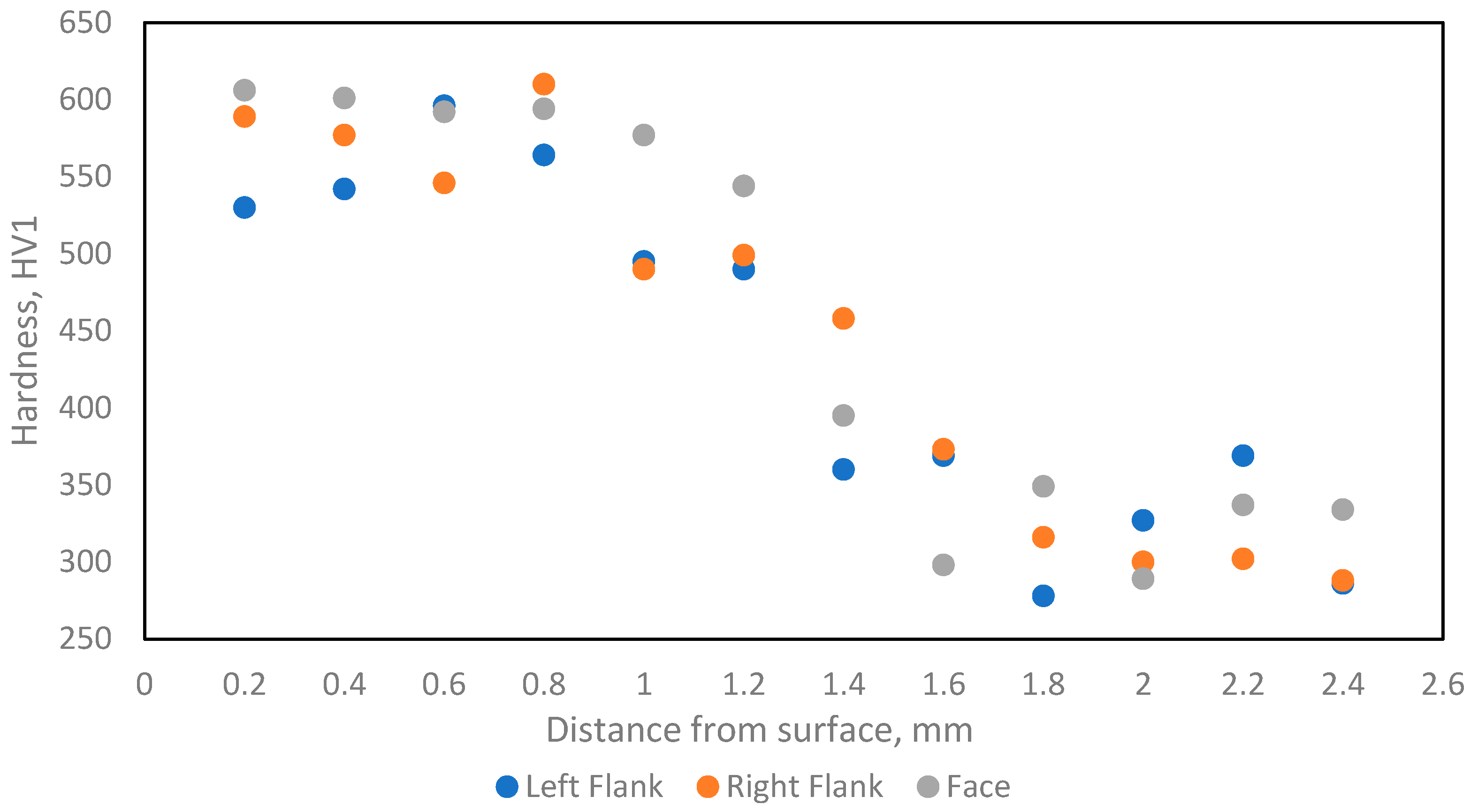
Hardness measurements for the near-surface zone showed only a slight difference in hardness, which was on average about 26 HV higher for the EBH-hardened layer, with the variation in measurement results being similar for both methods. The phase composition in the surface layer is nearly the same. Due to the lack of significant differences in morphology and phase composition, the slight differences in the hardness of both surface layers should be explained by differences in the stress state of the surface layer. This is because the accumulation of internal stresses can significantly affect the mechanical properties of the material, such as hardness, tensile strength, and impact strength. In the SigmaPhi 90° direction, in the surface layer, the stress levels increased by 131% in the case of the EBH sample and 48% in case of the LBH sample. In SigmaPhi 0°, the stress increases amounted to 92% and 133%, respectively. A detailed description of the relationship between internal stresses and the mechanical properties of the steel grade in question will be the subject of a separate study.
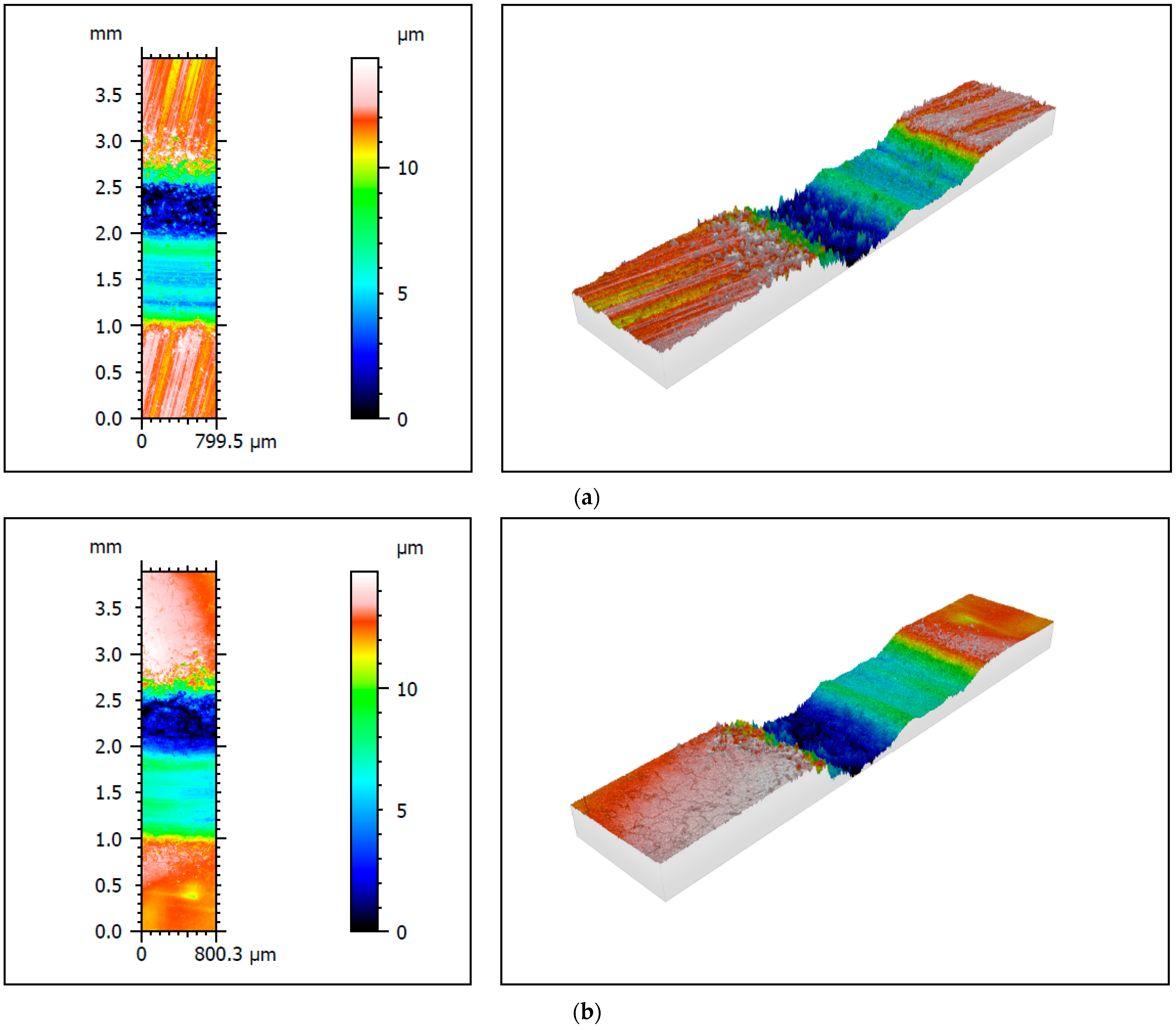
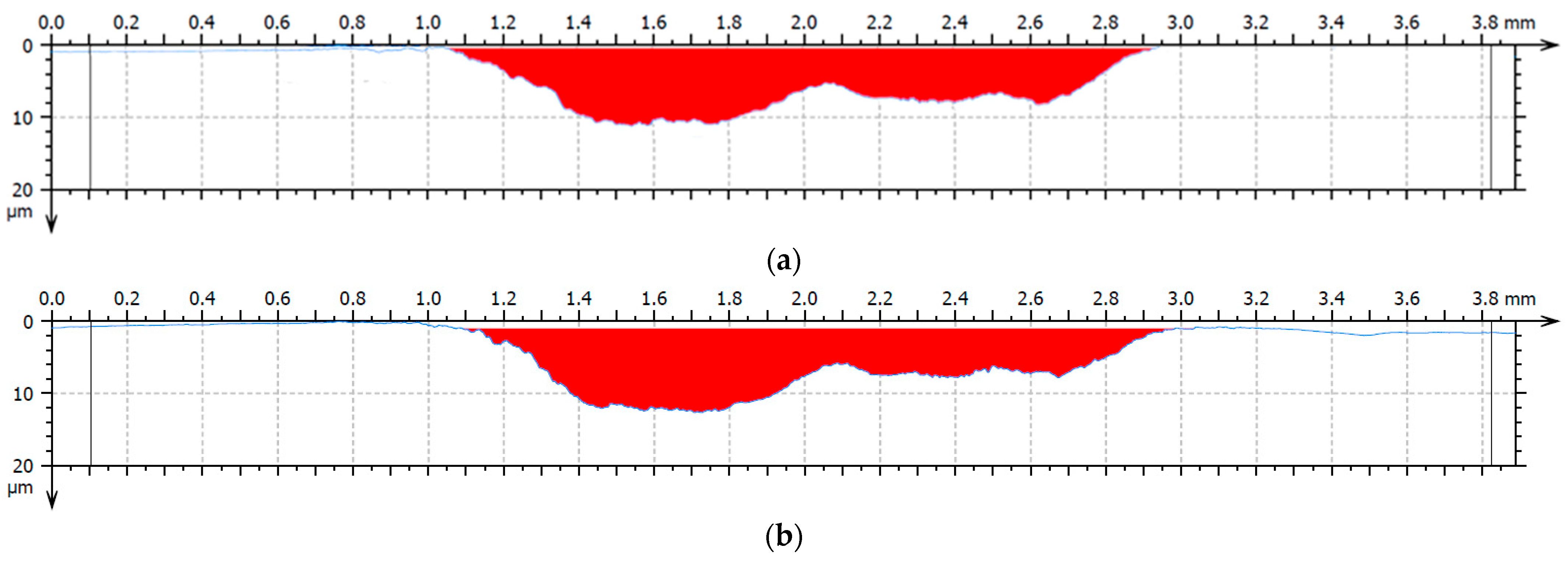
In both cases, the mark left after tribocorrosive wear caused directly by the tungsten counter-sample is clearly visible and the degree of wear is almost the same, with the EBH sample being slightly less worn (7.7% lower wear maximum depth and 1.5% smaller wear cross-sectional surface).
Figure 15 shows many oxidation products and typical longitudinal marks caused by the interaction with a sliding tungsten ball. The surface also shows cavities and microcracks typical for this type of wear.
In summary, it can be concluded that both methods provide a similar set of surface properties after hardening, with electron beam hardening achieving these effects with lower energy consumption and without oxidizing the hardened surface.
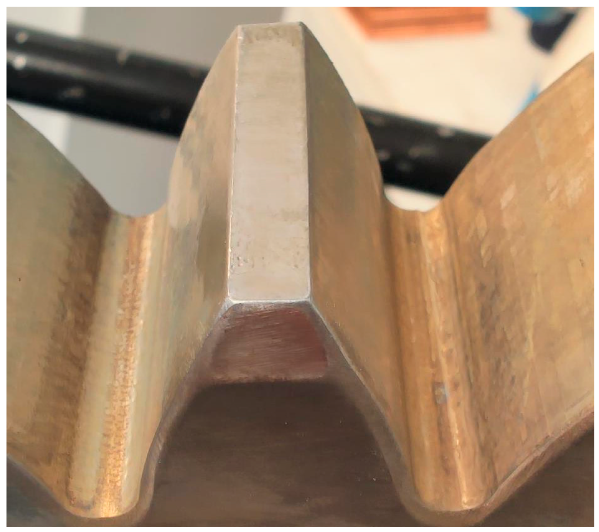
The results of electron hardening of gear teeth show that the use of this technology with an appropriate oscillation pattern enables the entire tooth to be hardened in a single pass, without melting or surface oxidation. The view of the hardened zone shows a gentle slope down to the base of the tooth, i.e., the zone where teeth most often break. This allows for practical application of the developed method in the production of surface-hardened gears made of steel with a submicron microstructure containing carbon-free bainite.

