1. Introduction
Stainless steel is one of the most successful and versatile materials in terms of applications. For instance, AISI 304 stainless steel has been used in a variety of petrochemical equipment, including platforms, vessels, piping, and tubing, as well as in domestic products, such as sinks and wash basins, cooking accessories, pots, pans, and flatware [
1]. However, none of these use cases remains free from corrosion, especially when exposed to aggressive media. In the case of marine environments, stainless steel is very susceptible to pitting corrosion, with the presence of chloride ions leaving it highly susceptible to damage from pits [
2,
3,
4,
5]. One of the most destructive and insidious forms of corrosion, pitting is defined as extremely localized damage leading to very small-scale degradation, which then grows into bigger holes in the metal [
6].
Aparicio et al. developed crack-free melting gel coatings for AISI 304 stainless steel of up to 1 mm in thickness that exhibit exceptional anti-corrosion performance. Electrochemical tests (Anodic Polarization and electrochemical impedance spectroscopy) were performed in 3.5% NaCl solutions, and after several months of immersion, no degradation was observed. The coating seems to remain unchanged during polarization, with breakdown potential only observed in this stage, suggesting that the film is highly stable at the surface [
7,
8].
A variety of materials have been studied for protecting AISI 304 SS against corrosion, including TiO
2 [
9,
10], SiO
2 [
11], ZrO
2 [
12,
13], Nb
2O
5 [
14], ZnO [
15], and Al
2O
3 [
16]. The sol–gel method and dip-coating technique are frequently used for preparing precursors and forming protective coatings. For instance, Curkovik and Akhtar developed TiO
2 and silane coatings, respectively, with the marine performance of the former evaluated via its electrochemical behavior in a 3 wt.% aqueous NaCl solution and 0.5 M aqueous HCl solution, and the latter evaluated in 0.6 M sodium chloride solution by Potentiodynamic Polarization and electrochemical impedance spectroscopy. The results showed that corrosion was largely reduced with both coating systems compared to the uncoated substrates [
9,
17].
On the other hand, tin dioxide (SnO
2) is a semiconductor with potential applications in optoelectronics, photoluminescence, and magnetism [
18], photocatalytic degradation [
19], gas sensors [
20,
21], etc., with such widespread use enabled by its high chemical and mechanical stability [
22].
Recently, SnO
2 coatings have been deployed on 304 stainless steel in order to enhance corrosion resistance in a simulated proton exchange membrane fuel cell (PEMFC) environment. These samples were subjected to corrosion tests using a H
2SO
4 solution, and favorable results were obtained, with a significant decrease in the corrosion current density from 33.22 to 0.1327 µA/cm
2 [
23]. In order to increase the application range of these coatings, TiO
2 was added as a supplementary component to improve the cathodic protection of metals against corrosion [
24].
In several studies, tin dioxide has been obtained via the sol–gel process using remnants of tin chloride from previous investigations as a precursor [
25,
26]; however, this has resulted in the presence of
ions [
27], which can accelerate corrosion. To avoid this inconvenience, tin oxide was synthesized with stannous oxalate as a precursor, again by the sol–gel method; in this case, as the oxalate is a small-molecule organic salt with carboxyl groups, it can be easily removed by calcination at low temperature during thin film formation [
28,
29].
The last fabrication method can be explained in terms of the ability to prepare functional coatings. Here, the sol–gel method offers the deposition of thin oxide films near to room temperature [
30,
31]. This process consists of the formation of composite networks by inorganic elements obtained through two simultaneous chemical reactions—hydrolysis and condensation; it is one of the most used methods for forming coatings because of its advantages of high homogeneity, low synthesis temperatures, and simplicity in covering complex shapes [
12]. This method is usually used alongside dip-coating, a simple film preparation technique that uses the controlled immersion and extraction of the substrate in the sol, producing products whose final properties are strongly dependent on heat treatment [
26,
27].
Therefore, this work aimed to prepare SnO2 coatings from two different precursors by sequential sol–gel and dip-coating techniques in order to prevent damage to 304 stainless steel substrates, additionally investigating changes in the corrosion behavior, surface structure, and chemical composition of the SnO2 coatings.
2. Materials and Methods
The corrosion resistance of 304 stainless steel was evaluated both in its uncoated state and after applying SnO2 coatings. The coatings were synthesized via the sol–gel method and deposited using the dip-coating technique.
2.1. SnO2 Synthesis by Sol–Gel Method
Two SnO2 syntheses were carried out using the sol–gel method, using two different precursors: SnCl2 and SnC2O4.
2.1.1. Synthesis from SnCl2 as Precursor
This synthesis followed a previously reported method—which takes tin (II) chloride (SnCl
2, Sigma Aldrich, St. Louis, MO, USA, 98%) and ethanol (C
2H
6O, Fermont, Monterrey, México, 99.9%) as the precursor and solvent, respectively [
25,
26]—the sol was prepared as follows: A 0.46 M sol of SnCl
2 was prepared in 35 mL of ethanol under vigorous stirring at 80 °C in a closed vessel. Subsequently, citric acid (C
6H
8O
7, Sigma Aldrich, 99.5%) was added to promote Sn-O complex formation, followed by the addition of 2 mL of diethyleneglycol (C
4H
10O
3, Sigma Aldrich, 99%) to increase the sol viscosity. Finally, 0.01 M of urea (CH
4N
2O, Fermont, 98%) was introduced to stabilize the reaction. The mixture was maintained at 70 °C with stirring throughout the entire process.
2.1.2. SnC2O4 as Precursor
The sol was prepared using tin (II) oxalate (SnC
2O
4, Sigma Aldrich, 98%) as the metal precursor and water (H
2O) and ethanol (C
2H
6O, Fermont, 99.9%) as solvents. First, 1.94 M of SnC
2O
4 was dissolved in 5 mL of distilled water, maintaining stirring in a closed vessel to form the initial suspension by hydrolysis. Then, 10 mL of a 1.16 M citric acid solution was added to form the Sn-O complex. Triethanolamine (TEA, (HOCH
2CH
2)
3N, Fermont, 99%) was added dropwise under stirring to form a clear sol and promote the ionization of the acids by H
+ consumption, which is a crucial base for the dissolution and chelation of SnC
2O
4 with C
6H
8O
7 [
28]. Finally, the sol was diluted with 20 mL of ethanol.
Additionally, samples of each sol were dried at 100 °C for 24 h to produce powders. These powders were then calcined at temperatures ranging from 200 to 500 °C for 1 h to determine the optimal heat treatment for SnO2 formation, which was characterized by FTIR and XRD.
2.2. Substrate Preparation
The substrate consisted of 304 stainless steel coupons with a chemical composition (wt.%) of 0.08% C, 0.75% Si, 2% Mn, 0.04% P, 0.03% S, 18%–20% Cr, 8%–11% Ni, and balance Fe. Prior to coating, the substrates were mechanically polished with abrasive paper, cleaned with distilled water, and degreased in an ultrasonic bath with acetone.
2.3. Coating Deposition on the Substrate
Film deposition was achieved via the dip-coating technique, controlling the rate of immersion and extraction (2.5 cm· min−1). After each deposition cycle, the coatings were heat-treated at 100 °C for 10 min to remove solvents, followed by a final treatment at 450 °C for 5 min to crystallize the SnO2. This dipping and heating cycle was repeated three times.
The coating synthesized with SnCl2 as a precursor produced one sample, denominated SnO2—Cl, and the SnC2O4 synthesis resulted in 3 samples, denoted as SnO2—Oxa (1), SnO2—Oxa (2), and SnO2—Oxa (3), to ensure reproducibility. These coatings were characterized by determining their respective corrosion protection, roughness, and crystal structure.
2.4. Characterization
The powders were analyzed by Fourier Transform Infrared (FTIR) spectroscopy using a Perkin Elmer Spectrum 65 system, Springfield, IL, USA, with the potassium bromide (KBr) technique. The analyses were carried out in the 4000 to 400 cm−1 range, since it is possible to observe the characteristic absorption bands of the synthesized materials in this spectrum. XRD patterns of the powder samples were recorded using Cu Kα radiation (1.5406 Å) and a scanning rate of 3° min−1 in the angle range of 20–80°.
To analyze the coatings, electrochemical measurements were performed using the polarization resistance technique (Rp) for corrosion rate, and corrosion protection was evaluated by Anodic Potentiodynamic Polarization using a 263A EG&G Instruments potentiostat/galvanostat, PalmSens BV, CL Houten, The Netherlands, and a three-electrode electrochemical cell. The measurements were performed at room temperature (22–25 °C) in a 3 wt.% aqueous NaCl solution. The XPS analysis was carried out using X-ray Photoelectron Spectroscopy equipment in a range of 50 to 600 eV, and the phase of the SnO2 coating on 304 stainless steel was determined by XRD using an X’Pert Pro PANalytical X-ray diffractometer, Malvern Panalytical Ltd., Malvern, UK, in the 2q range from 20 to 80° with CuKα radiation; beam angle and roughness were examined on scan area of 5.0 µm × 5.0 µm by atomic force microscopy (AFM). The surface morphology and elemental composition of the coatings were examined using a Hitachi TM3030 benchtop scanning electron microscope (SEM), Tokio, Japan, equipped with an energy-dispersive X-ray spectroscopy (EDS) detector. The analyses were performed at accelerating voltages of 5 and 15 kV to optimize image quality and elemental characterization.
3. Results and Discussion
Texture, morphology, material/alloy composition, and the presence of different phases strongly influence corrosion resistance. The following section describes the tests performed for the powders and coatings and their comparison based on the precursor used.
3.1. Chemical Evolution of the SnO2 Powder
To determine the chemical evolution of both sols, we analyzed FTIR results. First, the powders were dried at 100 °C for 24 h, followed by heat treatment at 200, 300, 400, 450, and 500 °C for 1 h in order to find the formation temperature of the SnO
2.
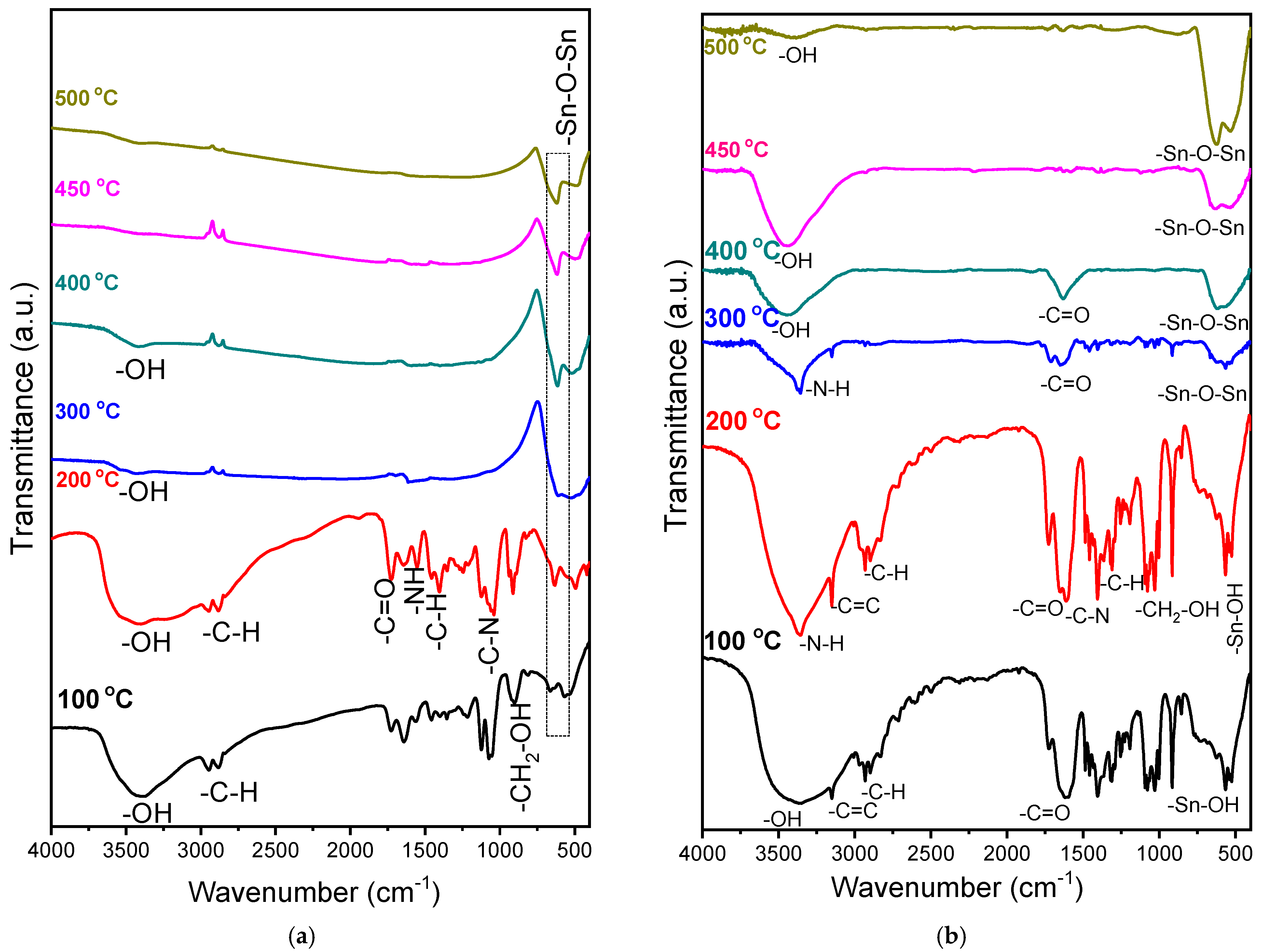
Figure 1 shows the chemical evolution of SnO
2 formation starting from SnCl
2 (a) and SnC
2O
4 (b) as precursors.
In both spectra, a band corresponding to hydroxyl group (OH) vibrations around 3600 to 3000 cm
−1 is observed. These peaks are due to the water in the system, and their presence at higher temperatures is due to environmental water adsorption during tablet preparation or incomplete drying of the sample [
32]. Increases in calcination temperature could reduce the intensity of these bands according to previous studies on the same matrix [
25]. It is known that physically absorbed water, in addition to the remnants of the solvents used in the reaction (in this case, water and ethanol), can be desorbed around 130 °C, while organic components are dissociated or oxidized for later evaporation in small molecules at around 250 °C [
33,
34]. In the section “a” of
Figure 1, carboxyl group vibrations are observed at around 1700 cm
−1, corresponding to citric acid; these bands disappear after the heat treatment at 300 °C, as do the vibrations from the organic groups present, including the N-H bond band belonging to urea at 1600 cm
−1 and the CH
2-OH band between 950 and 1150 cm
−1, coming from the ethanol used as a solvent.
In section “b”, one can also observe N-H vibrations that occur at about 3340 cm
−1 in the only pair of electrons free of the nitrogen belonging to the triethanolamine (TEA) when the acids are deprotonated [
35]. This band disappears at 400 °C, which coincides with the boiling temperature of the TEA—335 °C. Jun Liu mentions in his study the mechanism by which the electron pair of the TEA’s nitrogen consumes citric acid H
+ ions, forming oxalic acid and providing the system with carboxyl groups for tin complex formation [
28]. The absorption peaks corresponding to carboxyl ions, coming from citric acid and oxalate, and in the range of 1600–1800 cm
−1, are present from 100 °C and disappear only after heat treatment at 450 °C. The CH
2-OH groups between 950 and 1150 cm
−1, coming from the solvents used (ethanol), practically disappear at 300 °C.
With respect to Sn, in both cases, an absorption band can be seen at 540 cm
−1, corresponding to Sn-OH group bond formation coming from the hydrolysis stage of the metallic precursor with the ethanol heated to 100 °C. From 300 °C, the absorption bands at 520 and 640 cm
−1 are associated with the O-Sn-O bonds of the formed oxide [
35,
36]. These bands increase in intensity with temperature, and these results agree with previously published studies on SnO
2 formation [
36].
In summary, the analyses of the coatings formed with each precursor demonstrate the formation of Sn-O-Sn bonds from 300 °C upwards. Using a higher temperature, the formation of Sn-O bonds is ensured; however, using high temperatures could affect the mechanical properties of the substrate and is therefore not recommended, because under actual use conditions, if stainless steel is subjected to high temperatures in addition to oxidation, fragile phases can be formed that compromise the material’s behavior [
37]. These results determined that the required thermal treatment for both powders and coatings was 450 °C.
3.2. SnO2 Powder Microstructure
The results in
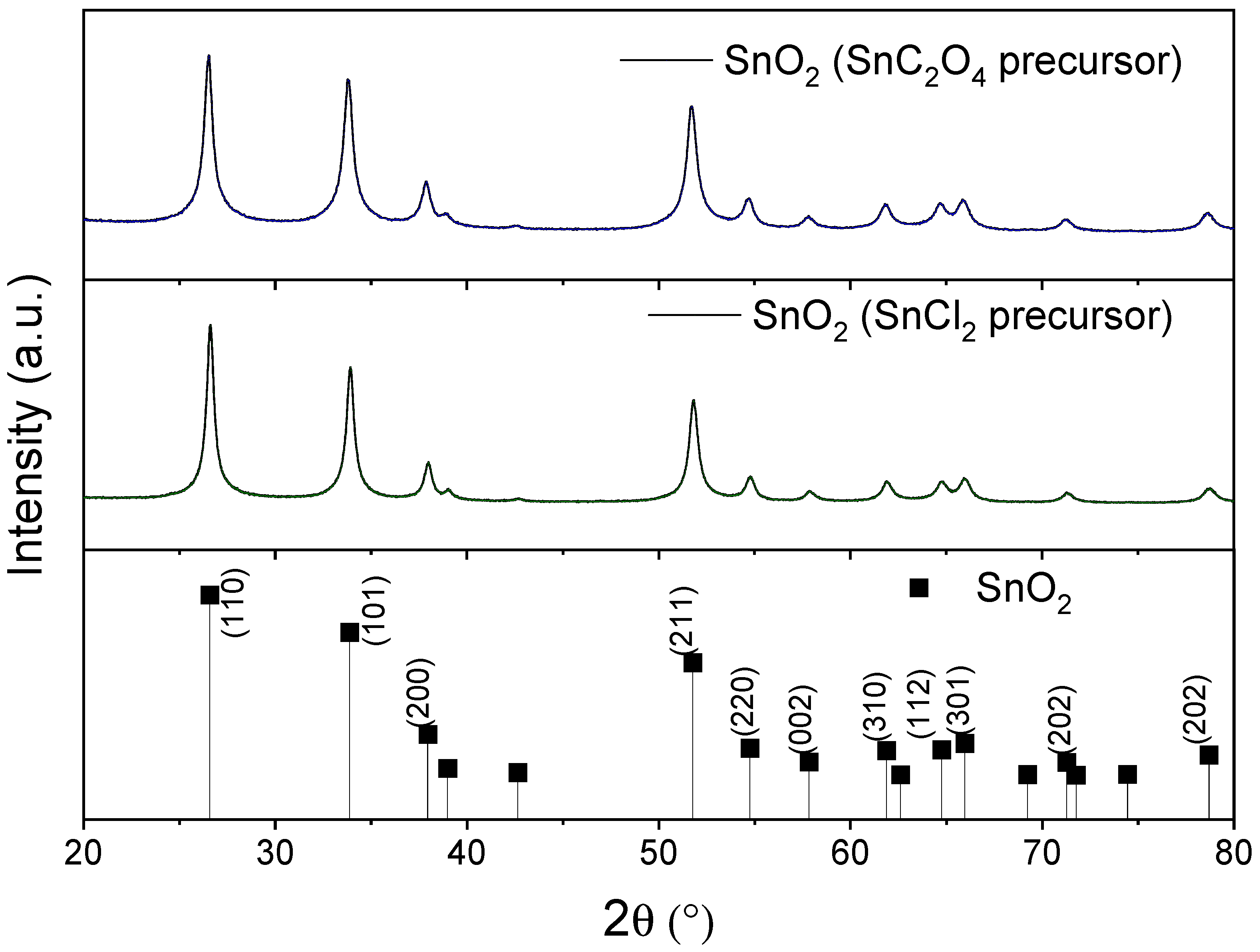
Figure 2 show that the SnO
2 cassiterite phase (JCPDS card No. 9007433, P 42/m) could be obtained via both synthesis routes without evidence of other species. On the other hand, it is also demonstrated that the selected heat treatment temperature was sufficient for the structuring of the material in both synthesis cases, using SnCl
2 or SnC
2O
4 as a precursor.
3.3. Corrosion Protection of SnO2 Coatings
The protective efficacy of the SnO2 coatings was evaluated through polarization resistance (Rp) measurements and anodic potentiodynamic polarization tests in a 3 wt.% NaCl solution. The results revealed a stark contrast in performance directly attributable to the precursor used.
3.3.1. Corrosion Resistance When Using SnCl2 as Precursor
The corrosion resistance of the SnO
2 coatings obtained from an SnCl
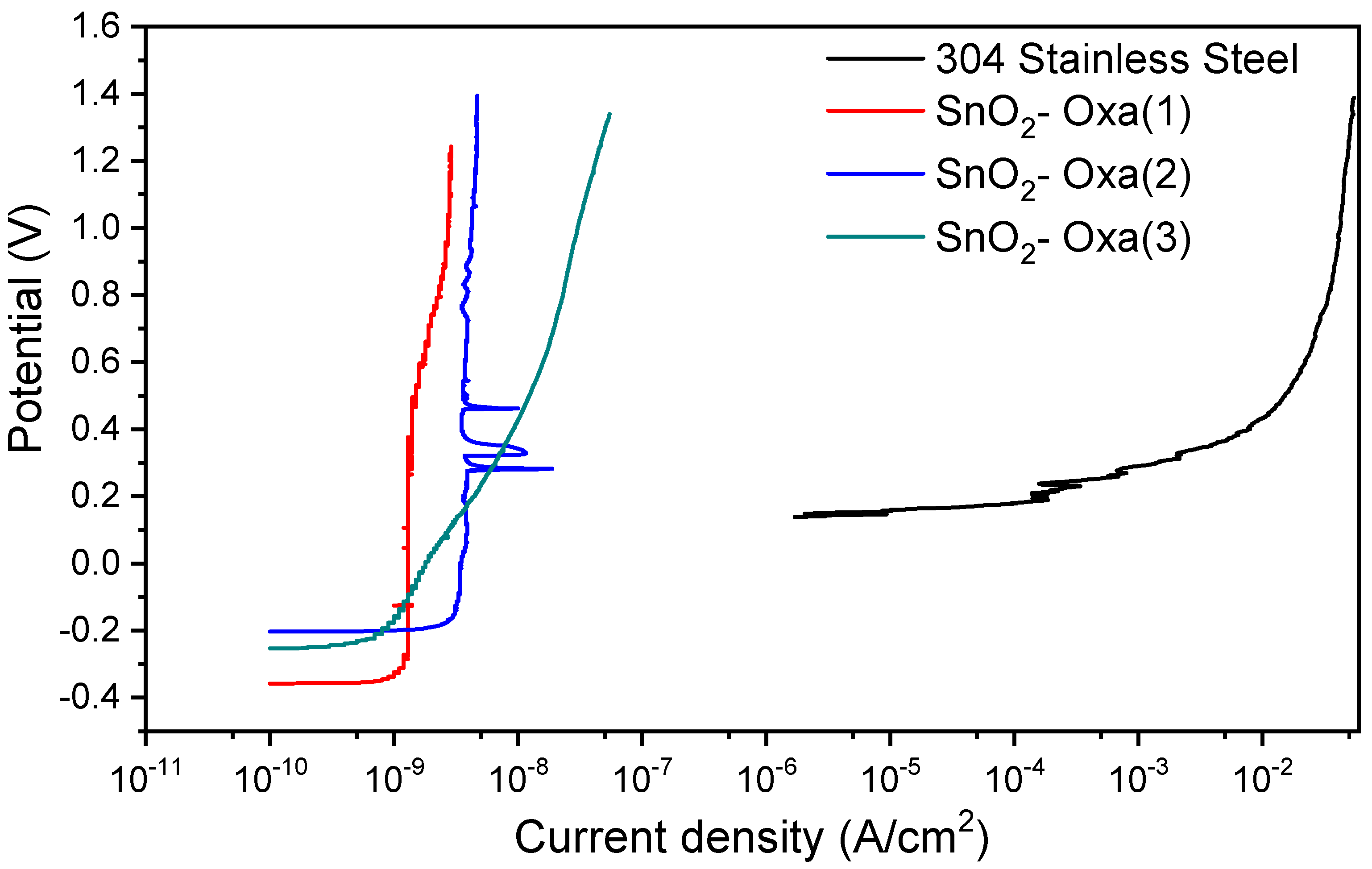
2 precursor was first evaluated, showing a complete failure to protect the 304 SS substrate. According to the obtained curves (
Figure 3). Although the open-circuit potential shifted slightly, (represented by the starting potential of the test), there was no decrease in the current density of the coated samples compared to the uncoated samples, indicating that there was no improvement in corrosion resistance (passivity tendency) since the coating did not fulfill the function of increasing the protection of the material; on the contrary, it accelerated the corrosion process. This is clearly demonstrated by the rightward shift in the anodic branch of the polarization curve for the SnO
2–Cl sample, which indicates a higher anodic dissolution rate and thus a lower tendency toward passivity. However, in terms of pitting corrosion resistance, which is influenced by coating homogeneity [
38] and represented by the breach of passivity, the coated samples showed improvements with respect to the uncoated sample, displaying a greater pitting potential compared to the base material. This suggests that while the SnO
2–Cl coating is porous or defective, allowing general corrosion, it may still hinder the localized breakdown of the passive film. This is shown in the figure through the upwards shift in the coated samples’ curves compared to that of the uncoated material.
The parameters obtained by means of the Rp test for the coatings are reported in
Table 1. Consistent with the polarization data, the Rp values confirm the detrimental effect, showing a higher corrosion current (Icorr) and a significantly lower polarization resistance for the SnO
2–Cl coating compared to the uncoated steel. Each reported data point corresponds to the average of three measurements of the same sample, and the standard deviation of the corrosion rate was calculated from these measurements.
3.3.2. Corrosion Resistance When Using SnC2O4 as Precursor
In contrast, all three replicate coatings synthesized from SnC
2O
4 exhibited exceptional corrosion protection. All these coatings responded to the corrosive medium with an improvement in corrosion resistance in reference to the uncoated material; that is, each of the synthesized coatings formed a protective barrier for the material. This can be observed by the pronounced leftward displacement of the potentiodynamic curves (
Figure 4), which signifies a substantial reduction in anodic current density and, consequently, a markedly lower corrosion rate because of the coating, which acts as a protective barrier on the substrate surface. The coatings also drastically improved the material’s resistance to localized attack.
The coatings also drastically improved the material’s resistance to localized attack. The pitting potential, defined as the potential where the current density increases continuously [
31,
39], was approximately 0.15 V for the uncoated steel. For all SnO
2–Oxa coatings, the pitting potential exceeded 1.2 V, representing more than an eight-fold increase and demonstrating the coating’s effectiveness in suppressing pit initiation.
Regarding the variations in current density observed in the curves corresponding to the SnO2 (2) coatings within the potential range of 0.25 to 0.5 V, they can be assumed to be due to defects present in the protective layer, potentially introduced during the heat treatment. These defects mean that the samples begin to corrode in certain more susceptible areas but tend to reestablish their passivity by forming layers of material that protect the substrate. This represents a favorable behavior for substrate coatings as it indicates that the coating can self-passivate and continue to exert its positive effect.
The parameters obtained by means of the Rp test for the coatings of the SnO
2 system are reported below in
Table 2.
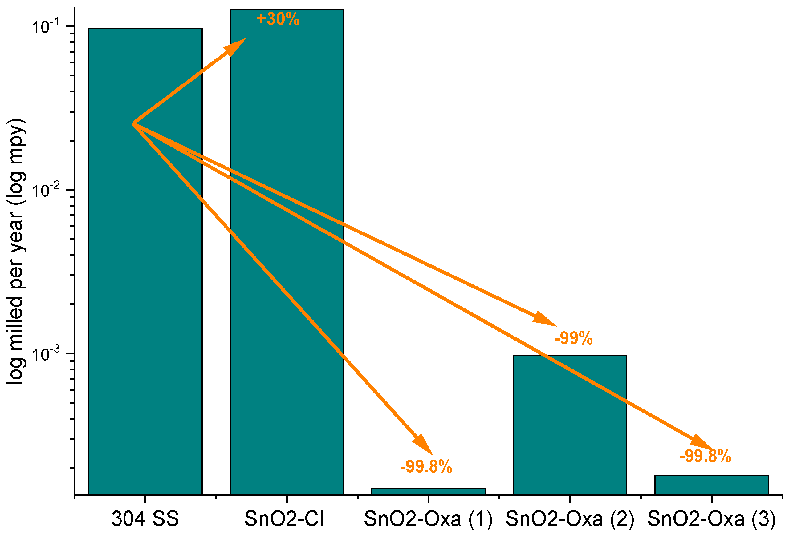
The data corresponds to the averages of three measurements of the same sample, for which the standard deviation for the corrosion rate was calculated. The samples with SnO2 coatings decreased their corrosion rate up to three orders of magnitude compared to the uncoated material; that is, a decrease ≈99% with respect to the uncoated sample was achieved.
Multiple oxide mixtures have been reported to function as protective barriers against corrosion, showing promising results [
9,
40,
41]; such is the case, for example, of M. J Zhou et al. [
42], who studied the properties of a TiO
2-SnO
2 film in terms of corrosion protection, obtaining good results in terms of decreasing the corrosion rate of the material. However, the protection achieved with the SnO
2 coatings fabricated in this study is more efficient than the other coatings. This behavior may be due to the fact that each of the oxides forms a protective layer on the substrate, increasing the passivity of the system and meaning that, when this barrier breaks, there is the possibility that the other oxides begin to form again a layer that reinstates the material’s passivation [
43]. In
Figure 5, the values of corrosion rate are plotted on a logarithmic scale to give a clearer example of the decrease in the corrosion rate when using the coatings. The increase in corrosion rate of the SnO
2-coated material with respect to the uncoated material is more evident in the sample formed with SnCl
2 as a precursor.
It has been shown that there is a relationship between electrochemical processes and the presence of Cl
− ions on materials’ surfaces, which produces a difference in the properties of the systems [
28]. Because this synthesis was based on the use of SnCl
2, Cl
− ions are present, as confirmed by XPS powder analysis, which could be the cause of the change in corrosion rate. The decrease in the corrosion rate when using coatings prepared from SnC
2O
4 is also evident in the case of the SnO
2-Oxa (1), (2), and (3) samples.
3.4. Elemental Analysis of SnO2 Powder with SnCl2 as Precursor
To elucidate the cause of the poor corrosion protection offered by the SnO
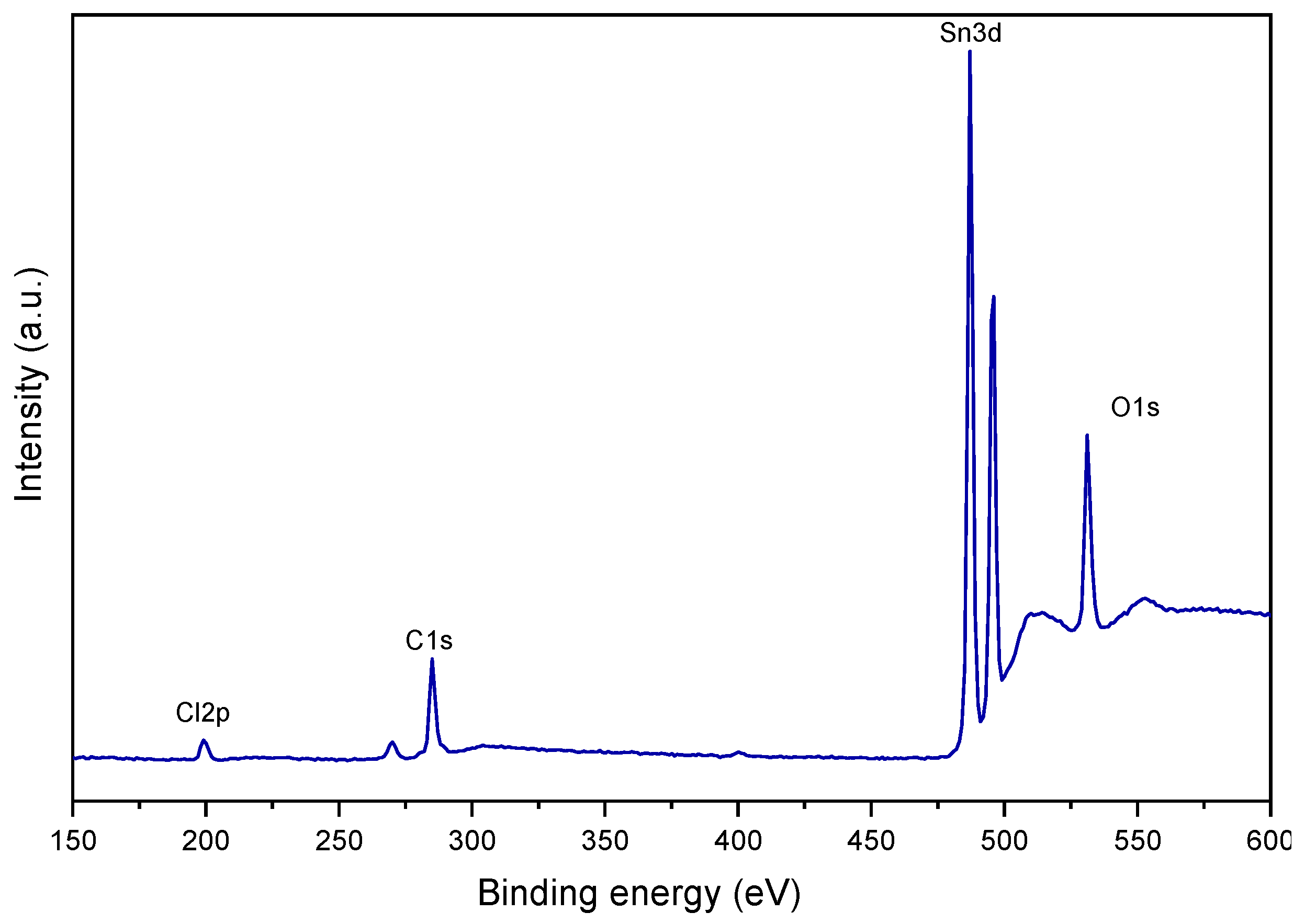
2–Cl coating, X-ray Photoelectron Spectroscopy (XPS) was performed to determine its elemental composition. (
Figure 6). In the spectrum, the characteristic bands of Sn (between 480 and 500 eV) and O (between 525 and 540 eV) can be observed, along with a distinct signal in the region between 190 and 205 eV, which is characteristic of chlorine (Cl 2p Quantitative analysis revealed a significant chlorine content of 5.54% by weight, which is attributed to the incomplete removal and decomposition of the SnCl
2 precursor during the sol–gel process. This finding provides a direct explanation for the electrochemical results.
The previous corrosion rate results showed an increase once the deposit was applied, and these XPS results allow us to conclude that this increase is due to the high content of Cl
− ions, which, as is well known, function as preferred sites for pitting initiation, as indicated by Evans [
44], who argues that if, for any reason, the rate of metal dissolution at a given point is momentarily high, chloride ions will migrate to this point and produce conditions that are favorable to further rapid dissolution. The presence of these chloride ions within the coating matrix fundamentally compromises its protective integrity. Rather than acting as a passive barrier, the SnO
2–Cl coating creates a highly aggressive interface at the substrate, facilitating rapid anodic dissolution. This explains the observed increase in corrosion current density (Icorr) and the rightward shift in the anodic polarization curve (
Figure 3), as the embedded chlorides actively promote both general and localized corrosion, effectively making the coating cathodic to the substrate and accelerating its degradation.
3.5. Structural Properties of SnO2 Coatings with SnC2O4 as Precursor
Based on the obtained corrosion protection results, the structural and morphological properties of the coatings made via SnO
2 synthesis starting from the SnC
2O
4 precursor were analyzed in order to understand the properties that this synthesis method provided. It is important to know the SnO
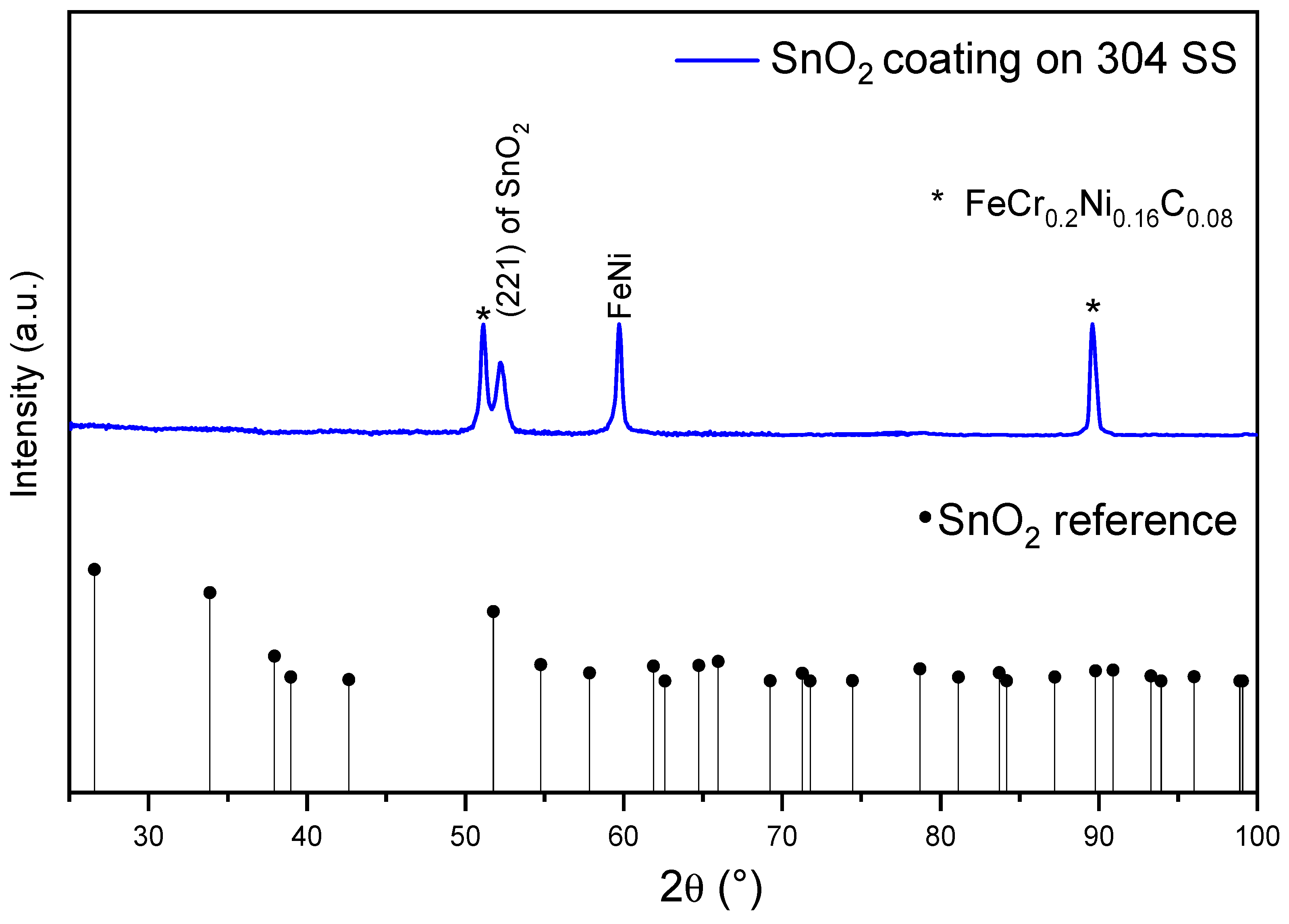
2 coating phase in order to support the synthesis of the material. The intensity of the (2 1 1) peak in the blue curve in
Figure 7 corresponds to the SnO
2 casitterite crystalline structure, with JCPDS 9007433 as a reference, indicating that it is textured; therefore, the majority of the material is oriented in the same direction, which is common in films and coatings and is influenced by synthesis parameters and substrate effects, with several authors finding preferential arrangements in various crystalline structures [
45,
46,
47].
Jin Jeong et al. [
48], suggest that, at 475 °C, when the atoms of Sn and O are distributed in the substrate and an SnO
2 thin film is grown, the (211) plane with the most kinetically stable orientation forms first, with the distribution of atoms representing relative activation barriers for growth and these units continuing to grow until the grains impinge upon each other. Once this occurs, the (110) plane exhibits a much more favorable growth tendency due to its energy being the most stable, as well as being the most thermodynamically and electrostatically stable, alongside the (101) plane [
22], which is also relevant, and will therefore grow faster than the (211) plane [
49]. It can therefore be determined that the reason the coatings are textured towards the (211) plane is due to the temperature and the heat treatment time, 450 °C and 5 min, respectively; therefore, increasing the temperature or time could modify the plane orientation of the coatings’ crystalline structure, as can also be observed in
Figure 7. The study by Gaarenstroom, where corrosion rates for ITO film electrodes grown using different sputter deposition conditions are compared, demonstrated that the most corrosion-resistant films had the best-formed crystals and showed the most crystal texturing [
50].
3.6. Morphology of SnO2 Coatings with SnC2O4 as Precursor
The surface morphology of the more efficient coating was examined by atomic force microscopy (AFM), with roughness measured on a scan area of 5.0 µm × 5.0 µm of SnO
2 coating. The images obtained, shown in
Figure 8 in both 2D (
Figure 8a) and 3D (
Figure 8b) formats, demonstrate a homogeneous surface with a slight accumulation of material in localized areas; despite these irregularities, the surface exhibits low roughness and is free of visible cracks. Previously, it was shown in the study by Hilbert et al. that a change in surface roughness can influence the corrosion protection properties of a material. In the study, the pitting corrosion resistance of a stainless steel was evaluated in NaCl solution, and the results indicated that electropolished and 4000-grit-polished steel proved more corrosion-resistant compared to 80- and 120-grit-polished surfaces. In conclusion, they mentioned that surface finish is an important parameter for corrosion resistance [
51]. A study on reactively sputtered ZrN coatings also found that corrosion resistance increases with decreasing grain size and surface roughness [
52]. Therefore, this work looks to achieve low-roughness, homogeneous coatings that suggest the good adhesion of the SnO
2 to the substrate, as well as a uniform distribution of the deposited material so as to provide protective corrosion resistance.
To assess the coating’s integrity and adhesion, the interface between the SnO
2 coating and the stainless-steel substrate was examined using Scanning Electron Microscopy (SEM) and Energy Dispersive X-ray Spectroscopy (EDS).
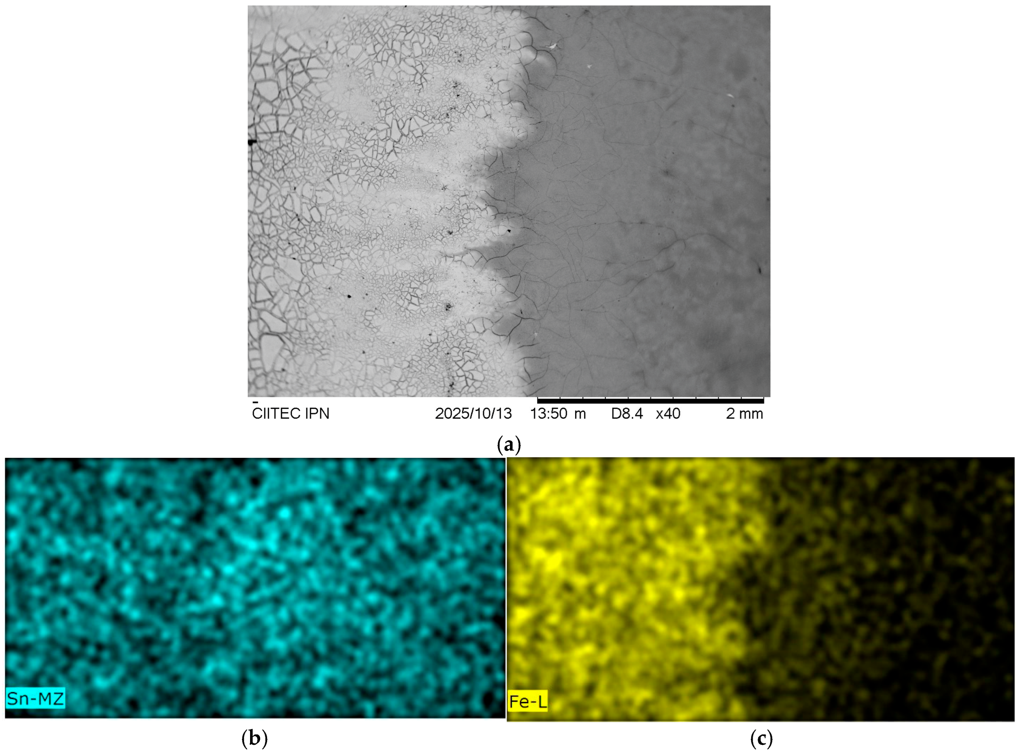
Figure 9a presents a top-view of this interface. The micrograph reveals two distinct regions: a continuous, fully covering SnO
2 coating on the right (gray area), which exhibits a homogeneous and uniform morphology, and an adjacent, cracked region on the left (brighter area). The EDS elemental mapping provides a clear chemical distinction between these zones. Tin (Sn) is detected across the entire field, confirming the presence of the SnO
2 layer,
Figure 9b, whereas iron (Fe) is exclusively detected in the cracked region,
Figure 9c. This indicates that the cracks extend down to the underlying steel substrate, which is exposed in this zone. This cracked morphology is attributed to the “run-off” effect during the dip-coating process, where the sol slurry drains and forms a mechanically unstable film at the edge of the coated area.
For a more direct assessment, a cross-sectional view was prepared by grinding the sample’s edge.
Figure 10a shows a tilted view of this cross-section, visually distinguishing the SnO
2 coating (gray) from the steel substrate (brighter tone). The corresponding EDS map
Figure 10b,c confirms this structure: the Sn signal is localized to the coating layer, while the Fe signal originates from the substrate and the freshly exposed edge.
A higher magnification view of the cross-section (
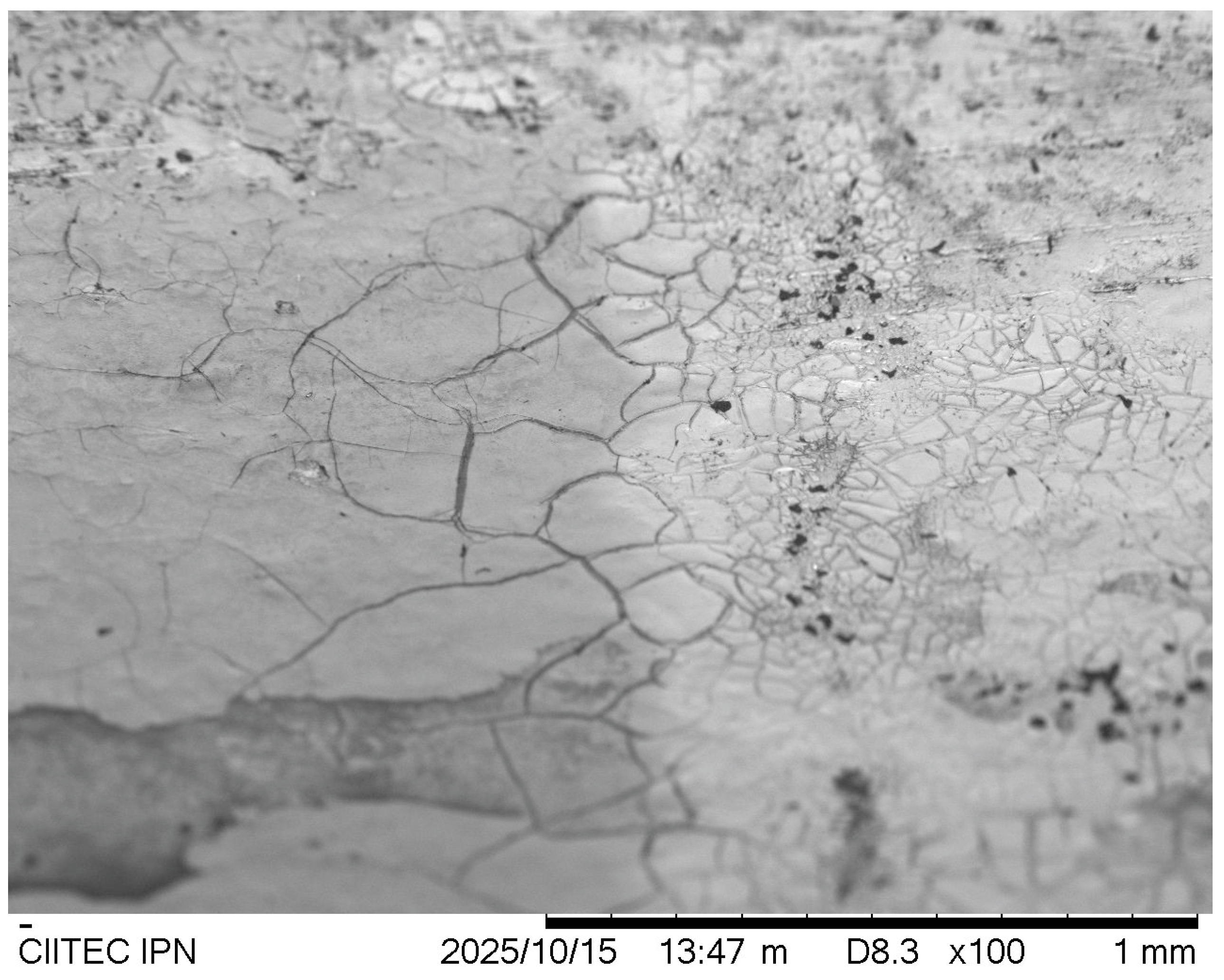
Figure 11) reveals the coating’s microstructure. The SnO
2 layer appears as a cohesive, yet cracked, solid film. The estimated thickness of this main coating is approximately 10 µm. The absence of an Fe signal from beneath this thick, central region confirms that the coating is fully dense and provides a continuous physical barrier. In contrast, the previously mentioned run-off region at the interface is much thinner (estimated <5 µm), explaining why its fine cracks readily allow for the detection of the underlying iron substrate, as seen in
Figure 8a.
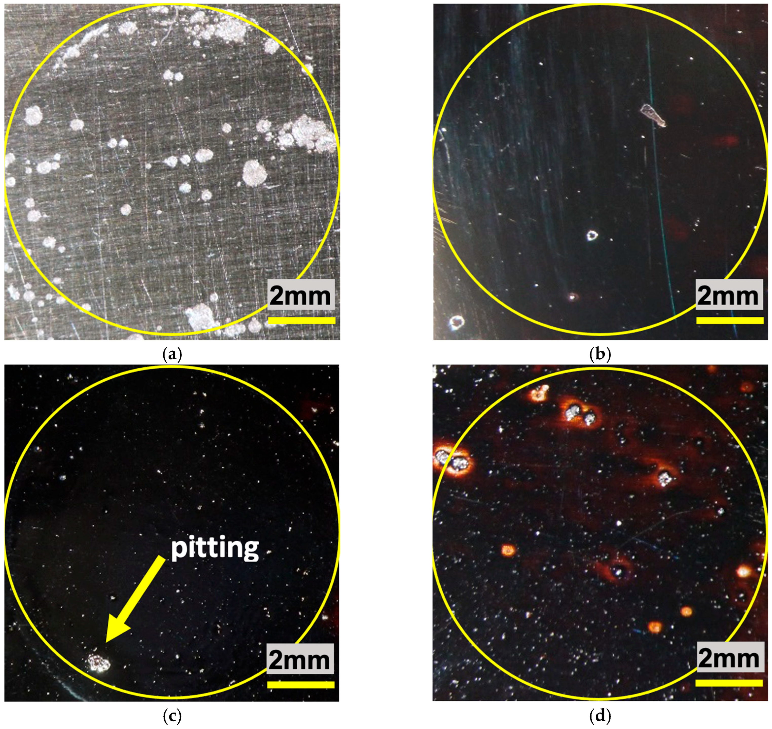
A series of images taken by means of a stereoscope is shown in
Figure 12, corresponding to the samples with and without SnO
2 coatings after having been subjected to corrosive attack.
It can be observed that the pitting presents, as expected, a higher concentration in the uncoated steel sample, while the sample corresponding to the coating that obtained the lowest corrosion rate—SnO2 (1)—shows greater homogeneity in terms of the protective layer. It is important to note that the heterogeneities observed in the latter do not correspond to pitting, but to small superficial defects in the protective barrier; however, as the corrosion rate results demonstrate, these defects do not accelerate the corrosion process. The SnO2 (3) sample shows pitting initiation due to some of the same superficial coating defects, although the test duration was not long enough to allow deep corrosion processes to take place, as can be seen in the case of SnO2 (2), in which a deep pit is present at the limit of the area exposed to the brine.
4. Conclusions
This study successfully demonstrates that the choice of precursor is a critical determining factor in the sol–gel synthesis of SnO2 coatings for corrosion protection, transcending its mere role as a tin source. While both SnCl2 and SnC2O4 yielded the desired cassiterite SnO2 phase, their electrochemical performance in a chloride environment was drastically different. The use of SnC2O4 precursor enabled the formation of a highly effective protective barrier. The resultant coating not only provided a physical shield but also significantly enhanced the passivity of the 304 stainless steel substrate, as evidenced by a reduction in corrosion rate by three orders of magnitude and an increase in pitting potential exceeding 1 V. This superior performance is due to the synergistic effect of the coating’s homogeneity, low roughness, and, crucially, its chemical purity.
Conversely, the use of SnCl2 was fundamentally counterproductive. The presence of residual chlorine (5.54 wt.%) within the coating, a direct consequence of the precursor chemistry, actively promoted corrosion initiation. Thus, the incorporation of aggressive ions from the precursor can compromise the coating’s protective function more severely than having no coating at all. Therefore, a chlorine-free synthesis route is not merely an alternative, but a strict prerequisite for developing high-performance SnO2 sol–gel coatings for service in chloride-containing environments. The SnC2O4 pathway presents a viable and robust method to achieve this, ensuring the intrinsic chemical stability of the precursor translates directly into superior and reliable corrosion protection. Future studies could be enhanced by electrochemical impedance spectroscopy (EIS) to study the long-term degradation mechanisms of these promising coatings.
Furthermore, SEM and EDS analyses at the coating-substrate interface provided critical microstructural evidence supporting the electrochemical results. The effective SnO2 coating derived from SnC2O4 presents as a homogeneous, continuous, and fully covering layer with an estimated thickness of 10 µm, which explains its role as an effective physical barrier that prevents the detection of the underlying iron substrate.
