Article

High-Temperature Sulfate Corrosion Resistance and Wear Performance of NiCr-Cr3C2 Coatings for the Water Wall of Power Plant Boilers

1
College of Materials Science and Engineering, Hohai University, Changzhou 213022, China
2
Wuhu Power Generation Co., Ltd., China Power International Holding Ltd., Wuhu 241000, China
3
Shanghai Power Equipment Research Institute, Shanghai 200240, China
*
Authors to whom correspondence should be addressed.
Coatings 2025, 15(10), 1152; https://doi.org/10.3390/coatings15101152
Submission received: 12 September 2025 / Revised: 22 September 2025 / Accepted: 24 September 2025 / Published: 3 October 2025
(This article belongs to the Special Issue Anti-Corrosion Coatings: New Ideas to Make Them More Effective)

Abstract

Water walls in power plant boilers are prone to failure under extreme conditions involving high temperature, corrosion, and wear, which severely threaten unit reliability and operational economy. In this work, a NiCr-Cr3C2 protective coating was deposited on SA213-T12 steel substrates using high-velocity oxy-fuel (HVOF) spraying, with arc-sprayed PS45 coating as a reference. The NiCr-Cr3C2 coating exhibited a dense, low-porosity structure with homogeneous dispersion of Cr3C2 hard phases in the NiCr matrix, forming a typical cauliflower-like composite morphology. During high-temperature sulfate corrosion tests at 750 °C, the NiCr-Cr3C2 coating demonstrated superior corrosion resistance, with a weight gain of only 2.7 mg/cm2, significantly lower than that of the PS45 coating and the SA213-T12 substrate. The higher microhardness and lower friction coefficient also indicate excellent high-temperature wear resistance. The enhanced performance of the NiCr-Cr3C2 coating is attributed to the high Cr content, which promotes the formation of a continuous and protective scale composed of Cr2O3 and NiCr2O4, effectively inhibiting corrosive diffusion and penetration. This work demonstrates the application prospects of NiCr-Cr3C2 coatings on water walls of power plant boilers and guides the development of advanced HVOF coatings.

1. Introduction

Coal is the world’s most abundant fossil fuel, and its relatively low cost makes it a crucial fuel for power generation [1,2,3]. However, the extensive combustion of coal also brings negative environmental impacts, making improvements in power generation efficiency essential for the sustainable development of the coal power industry. This has led to an increase in the proportion of large-capacity, high-parameter supercritical and ultra-supercritical coal-fired units [4,5,6]. With the upgrading of power plant equipment, higher temperature and pressure requirements have also increased the risk of boiler tube leaks [7,8,9,10]. Water walls are critical heating components in the boiler furnace, responsible for absorbing high-temperature thermal radiation to prolong the service life of the furnace. High-temperature, high-speed flue gas erosion and high-temperature corrosion are the main factors causing water wall failures [11]. Even after necessary purification, coal may still contain sulfur and alkali metals (Na, K). These impurities form sulfates during combustion or oxidation, and such sulfates (e.g., Na2SO4, K2SO4) readily adhere to the surfaces of high-temperature components. Sulfate-induced corrosion is considered one of the primary causes of high-temperature corrosion, mainly occurring on surfaces such as boiler water walls [12]. Since composite sulfates formed from alkali metal oxides and sulfur in coal ash deposits easily adhere to tube walls and are difficult to remove, and high-speed flue gas erosion readily causes damage to water wall surfaces, preventing high-temperature sulfate corrosion and enhancing the wear resistance of water walls have become urgent issues in materials protection.
Thermal spraying technology offers a wide range of applications, with its excellent on-site processing adaptability and relatively low production costs making it widely employed in the protection of coal-fired boilers. Common thermal spraying techniques include arc spraying, plasma spraying, high-velocity oxy-fuel (HVOF) spraying, and laser spraying. Owing to its low cost, high process efficiency, operational safety, and broad coating applicability, arc spraying is extensively used in the power industry [13,14,15,16]. The PS45 (NiCrTi alloy) coating exhibits performance comparable to the 45CT coating (from TAFA Inc., Concord, NH, USA) at a significantly lower cost, and has been widely applied to protect water walls against high-temperature corrosion and erosion [17]. Due to the increasing requirements for the service performance of power generation units, protective coatings for water walls must demonstrate enhanced corrosion resistance, wear resistance, and thermal conduction efficiency. However, the traditional PS45 coating faces high cost due to rising nickel prices, while its limited thermal conductivity and wear resistance further constrain the protective capability. It is urgent to develop new low-cost materials capable of withstanding synergistic degradation in extreme environments. NiCr-Cr3C2 is an advanced metal/ceramic composite coating material. Compared with conventional Ni-Cr alloy coatings, the incorporation of high-hardness and thermally stable Cr3C2 hard phases enhances the performance. The coating consists of a NiCr binder phase and Cr3C2 hard particles. NiCr is often used as a heat-resistant, oxidation-resistant bonding layer for high-temperature ceramic coatings, while Cr3C2 offers the best oxidation resistance among metal carbides [18,19]. Ghosh et al. [20] fabricated this coating on 2.25Cr-1Mo steel via atmospheric plasma spraying and demonstrated its effectiveness in improving corrosion resistance during isothermal hot corrosion tests at 523 °C, attributing the performance to the formation of a protective Cr3C2 layer.
HVOF spraying, as a relatively novel, cost-effective, and rapidly developing thermal spraying technique, is suitable for a variety of coating materials (such as ceramics, metals, cermets, and alloys). Due to the high flame temperature and high particle velocity (400–1000 m/s), HVOF enables molten/semi-molten powder particles to fully deform and impact the substrate at high speeds. Hussain et al. [21] evaluated the performance of various chromium-containing coatings deposited on boiler tubes. Their findings demonstrated that the NiCrAlY coating, which possessed the highest chromium content, exhibited the best resistance to high-temperature corrosion. Yadav et al. [22] revealed that coatings prepared by HVOF spraying offer significant advantages over those produced by low-velocity oxy-fuel (LVOF) spraying. Notably, HVOF serves as a primary method for preparing NiCr-Cr3C2 coatings [23,24,25].
Schuber et al. [26] deposited the coating on turbine steel using HVOF and observed mechanical degradation after 168 h of corrosion in a mixed salt environment (59% Na2SO4 + 34.5% KCl + 6.5% NaCl) at 525 °C and 575 °C, but noted that a dense oxide film formed on the surface provided effective protection for the substrate. Chatha et al. [27] applied a NiCr-Cr3C2 coating on T91 steel using HVOF and compared its performance with that of bare steel in molten Na2SO4-60% V2O5 salt at 750 °C.
They found significantly improved corrosion resistance, which resulted from the formation of protective Ni/Cr oxides or spinel phases in the surface oxide layer. M. Oksa et al. [28] sprayed three different Ni-Cr coatings onto carbon steel pipes using ultra-high-velocity oxygen-fuel spraying and conducted a two-year field test in a power plant boiler. All three coatings exhibited excellent high-temperature corrosion resistance. Somasundaram B et al. [29] compared the performance of an HVOF-sprayed (Cr3C2–35% NiCr) + 5% Si coating on three different iron-based steel substrates. This superior performance resulted from the formation of a dense protective oxide layer, which was primarily composed of Cr2O3, SiO2, NiCr2O4, and Ni2(SiO4). However, due to the complex and harsh environment of power station boilers, the sulfate corrosion resistance and erosion-wear performance of coatings under high-temperature flue gas conditions still require in-depth investigation.
Currently, limited research exists on the high-temperature sulfate corrosion resistance and wear resistance of NiCr-Cr3C2 coatings applied to water-cooled walls in high-temperature boilers. Therefore, this study deposited HVOF-sprayed NiCr-Cr3C2 coatings onto SA213-T12 steel substrates and compared them with the PS45 coating commonly used on water walls in power boilers. The high-temperature sulfate corrosion resistance and elevated-temperature wear resistance of the NiCr-Cr3C2 coating were systematically investigated. The corrosion resistance mechanism was discussed based on corrosion kinetics and corrosion product analysis. The high-temperature tribological performance was scientifically evaluated through friction coefficient and three-dimensional wear scar morphology analysis, aiming to indirectly reveal the coating’s erosion resistance potential in high-temperature dust-laden flue gas environments. This study provides insights into the application of HVOF-sprayed NiCr-Cr3C2 coatings on water walls in power station boilers.

2. Experiment

2.1. Materials

The substrate material used in this study was commercial SA213-T12 steel, widely employed in ultra-supercritical coal-fired boiler water walls owing to its good plasticity, thermal toughness, and low cost. The NiCr–Cr3C2 coating was fabricated using commercial NiCr–Cr3C2 powder, which exhibited a spherical morphology with a gray–white color and smooth surface. Figure 1 presents the microstructure of the powder observed by scanning electron microscopy (SEM), and its chemical composition was analyzed via energy-dispersive spectroscopy (EDS) (Table 1). The reference coating was prepared using commercial PS45 wire, whose composition is shown in Table 2.

2.2. Thermal Spraying Process

The PS45 coating was applied by high-velocity arc spraying, and the NiCr–Cr3C2 coating by HVOF spraying. Before deposition, the substrates were degreased with acetone, air-dried, and grit-blasted. The PS45 coating was deposited using a twin-wire arc system (JZY-250, Beijing Jiazhiyuan Technology and Trade Co., Ltd., Beijing, China) equipped with a Laval nozzle to increase in-flight particle velocity for improved coating quality. The spraying parameters were summarized in Table 3 [17]. The NiCr–Cr3C2 coating was fabricated using a JP-8000 HVOF system (Praxair, Indianapolis, IN, USA), with the specific spray parameters listed in Table 4 [30,31].

2.3. Microstructural Characterization of the Coatings

The surface morphology, microstructure, and chemical composition of the sprayed coatings were systematically characterized using a CX-200 scanning electron microscope (Coxme CX-200 plus, Daejeon, Republic of Korea) equipped with an energy-dispersive spectrometer (EDS; Oxford Instruments, Oxford, UK). Phase identification of the coatings and high-temperature corrosion products was conducted using a D8 X-ray diffractometer (Bruker AXS, Karlsruhe, Germany) with Cu Kα radiation operated at 40 kV and 40 mA. The X-ray diffraction (XRD) analysis was conducted over a 2θ range from 20° to 90°.

2.4. Microhardness and Bonding Strength of the Coatings

The microhardness of the substrate and coatings was measured using an HXD-1000TC (Shanghai optical instrument factory no.1, Shanghai, China) microhardness tester under a load of 300 g with a dwell time of 15 s. Using the coating/substrate interface as the origin of the coordinate system, measurements were performed at 50-micrometer intervals through the coating cross-section. The average of three tests for each point was taken.
The bonding strength of the coatings was evaluated using a hydraulic universal tensile testing machine in accordance with ISO 14916:2017 [32]. The surface area of the coating was measured before the test. Loading bars were adhesively bonded to the sample using E-7 adhesive (Shanghai Synthetic Resin Research Institute, China) after cleaning and grit blasting. The assembled specimen was cured in an oven at 100 °C for 3 h. After cooling, the specimen was mounted onto the testing machine and subjected to tension at a crosshead speed of 1 mm/min until fracture. The maximum load was recorded.

2.5. High-Temperature Sulfate Corrosion Test

The high-temperature corrosion test samples consisted of SA213-T12 steel substrates, PS45-coated samples, and NiCr-Cr3C2-coated samples. Each sample had an exposed corrosion area of 20 mm × 10 mm. Before testing, all samples were ultrasonically cleaned in alcohol for 15 min and subsequently dried at 150 °C for 3 h. Cyclic high-temperature sulfate corrosion experiments were conducted in a KSL-1100X-S box-type electric furnace at 750 °C. An aqueous solution of Na2SO4 and K2SO4 with a molar ratio of 7:3 was prepared using distilled water and brushed uniformly onto all six surfaces of the samples. The salt-coated specimens were then placed in small crucibles and dried in an oven at 150 °C for 3 h to remove crystalline water, thereby simulating sulfate corrosion. The high-temperature corrosion test had a total duration of 100 h, including five initial one-hour cycles followed by additional five-hour cycles. The sample was cooled to room temperature and weighed after each cycle; then, it was recoated with salt, dried, weighed again, and returned to the furnace for the next cycle. Cumulative weight gain data from the hot corrosion tests were used to plot the hot corrosion kinetics curves. Weight changes were measured using an electronic balance (FA2004N; Jinghai Instruments, Shanghai, China) with a sensitivity of 0.1 mg, and corrosion kinetics were established based on weight change data at the end of each cycle. The microstructure and phase composition of the corrosion products were characterized by SEM, EDS, and XRD.

2.6. High-Temperature Tribological Performance Test of Coatings

High-temperature friction and wear tests were conducted on an MFT-5000 multi-function tribometer (RTEC, San Jose, CA, USA) using a ball-on-disk configuration. A Si3N4 counter ball was mounted in a specially designed pin holder, fixed to the rotating spindle via a custom fixture. The wear track radius and normal load were controlled by adjusting the vertical and horizontal positions of the Si3N4 ball. Friction force and coefficient of friction were monitored in real time during the experiment. The sample was heated to the target temperature and held for 10 min before initiating the test. The test parameters were as follows: temperature: 750 °C, wear track radius: 5 mm, load: 10 N, sliding speed: 0.105 m/s, and sliding distance: 0.38 km.
After the test, the friction coefficient data were recorded. The macroscopic three-dimensional morphology of the wear scar was examined using a LEXT-OLS4000 3D optical profiler (Olympus, Tokyo, Japan), and two-dimensional cross-sectional profiles of the wear track were obtained. The microstructural morphology and elemental composition of the worn surface were characterized by SEM and EDS.

3. Results and Discussion

3.1. Microstructural Characterization of Coatings

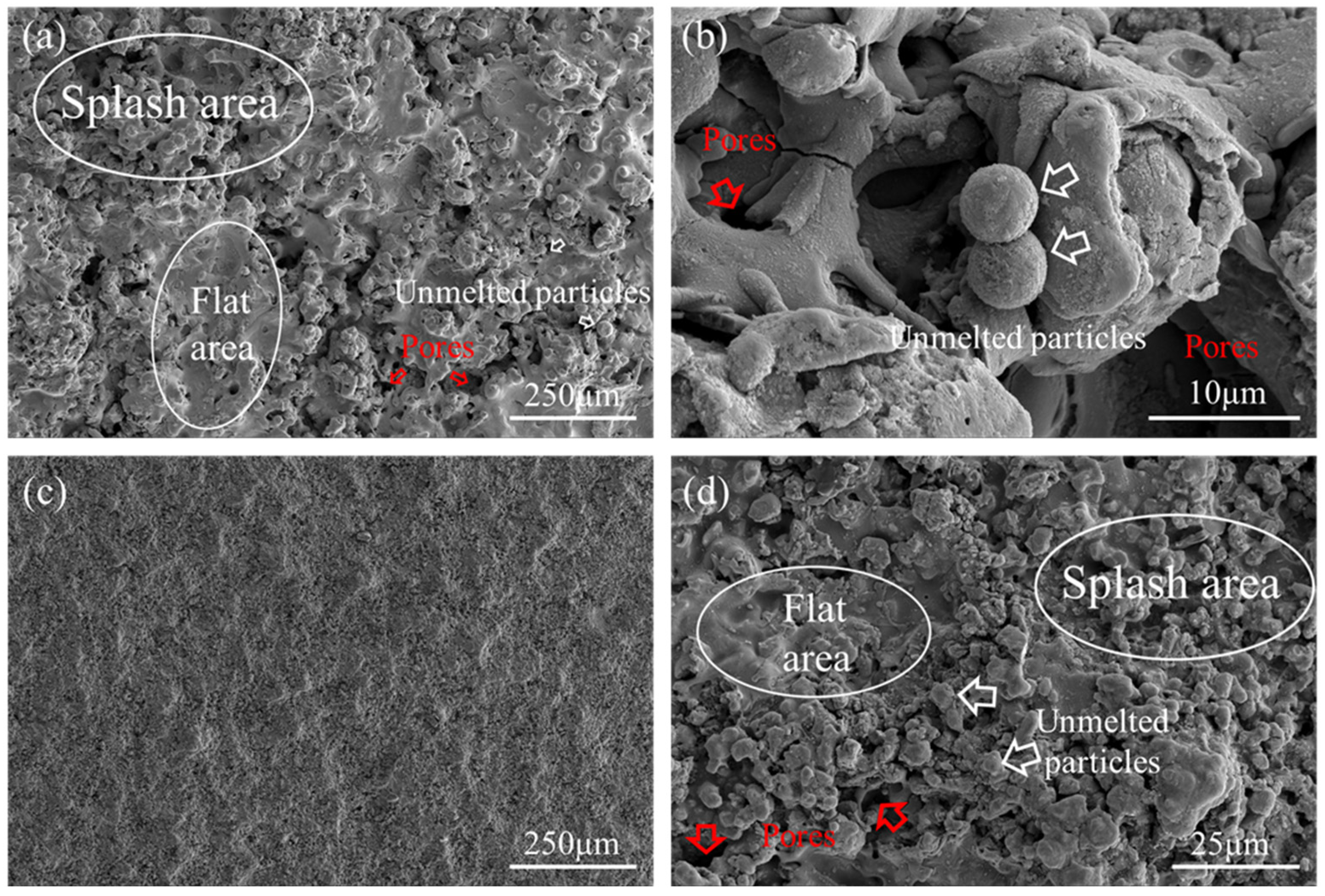
Figure 2 presents the surface morphologies of the PS45 and NiCr–Cr3C2 coatings. PS45 coating surface exhibited relative roughness, primarily comprising larger, flattened spatter patches formed by the diffusion of molten particles during thermal spraying, accompanied by several smaller spatter areas (see Figure 2). The flattened areas appeared relatively smooth. Pores and incompletely melted or unmelted spherical particles were also visible (Figure 2b), which were primarily attributed to insufficient melting of particles caused by low arc power. In contrast, Figure 2c shows that the NiCr–Cr3C2 coating prepared via HVOF spraying presented a much smoother and more continuous surface with no significant undulations, owing to the higher flame temperature promoting more complete melting of the powder particles. Figure 2d reveals that the coating surface consisted mainly of fully melted and solidified regions, interspersed with a small amount of partially melted particles, displaying a typical cauliflower-like morphology. During spraying, the molten/semi-molten NiCr particles impacted the substrate at high velocity and solidify to form the coating matrix, while the high-melting-point and high-hardness Cr3C2 particles were embedded within the NiCr binder phase. Overall, the optimized HVOF process parameters significantly improved the flattening behavior of the droplets.
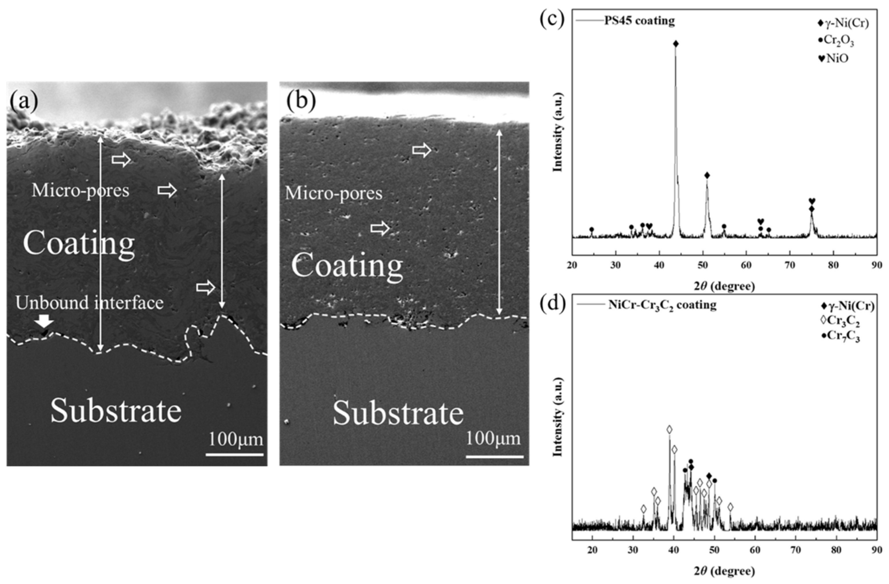
Figure 3 presents the cross-sectional SEM morphologies of the two coatings, both exhibiting similar overall thickness. PS45 coating exhibited a layered structure with a deformed cross-section (see Figure 3a). The layers were densely bonded but contained numerous pores. The interface between the coating and the substrate was irregular and uneven. The coating thickness was uneven, ranging from approximately 220 μm at the thinnest regions to about 340 μm at the thickest. This morphology was attributable to the high melting point of PS45, which resulted in incomplete fusion of the alloy droplets during spraying.
As shown in Figure 3b, the NiCr–Cr3C2 coating had a uniform and dense cross-sectional structure with an average thickness of about 330 μm. No obvious delamination, cracks, or large aggregated pores were observed, and unmelted spherical or semi-spherical particles were absent. The coating adheres tightly to the substrate via mechanical interlocking, with good interfacial bonding. The grit-blasting pretreatment before spraying resulted in a moderately undulating interface. The phases are closely interconnected without significant oxide inclusions, indicating sufficient melting and deformation of the NiCr–Cr3C2 particles during spraying and excellent flattening behavior. The coating contained a small number of pores because of poor wetting between the NiCr alloy matrix and the Cr3C2 hard particles after curing, as well as trapped gases that were not fully removed during the curing process.
The inherent pores in thermal spray coatings can serve as diffusion pathways for corrosive media, significantly compromising their high-temperature corrosion resistance and reducing bonding strength, which may lead to coating spallation. During arc spraying, the rapid solidification of molten droplets tends to trap gases, and interlamellar interfaces are prone to pore formation, resulting in generally high porosity. In contrast, the HVOF process benefits from high droplet temperatures, low oxygen content, and extremely high particle velocity and momentum, which promote sufficient spreading of molten droplets and liquid-phase diffusion, effectively feeding and closing pores. Simultaneously, the elevated temperature facilitates gas escape, collectively contributing to a significant reduction in porosity and yielding a denser, more homogeneous microstructure.
The average porosity was calculated using Image-Pro Plus software (Ipp6.0) by analyzing 10 randomly selected metallographic images of coating cross-sections. The mean porosity values for the PS45 and NiCr–Cr3C2 coatings were 4.03% and 1.54%, respectively. These results are consistent with the aforementioned SEM observations, confirming that the HVOF-sprayed NiCr–Cr3C2 coating exhibits significantly lower porosity and a denser structure with fewer defects.
The XRD pattern of the PS45 coating (see Figure 3c) shows the γ-Ni(Cr) solid solution as the primary phase, accompanied by diffraction peaks for Cr2O3 and TiO2. This indicates partial oxidation of the coating during the high-temperature arc spraying process. As observed in Figure 3d, the main phases of the NiCr–Cr3C2 coating consist of the NiCr solid solution and the Cr3C2 hard phase. A small amount of Cr7C3 is also detected, suggesting that partial decarburization of Cr3C2 occurred during the high-temperature spraying process. Cr3C2 is a metastable carbon-supersaturated phase, and the rapid cooling during spraying led to the formation of supersaturated carbide. Owing to the low oxygen content and extremely high particle velocity in the HVOF process, no significant oxide has been detected in the NiCr–Cr3C2 coating.

3.2. Mechanical Properties of the Coatings

The microhardness distribution across the cross-sections of the PS45 coating and the NiCr–Cr3C2 coating is detailed in Figure 4. Due to intrinsic defects such as pores and microcracks, the hardness distribution within the coatings is highly non-uniform. The average microhardness of the PS45 coating was 317 HV0.3, only slightly higher than that of the SA213-T12 steel substrate. In contrast, the NiCr–Cr3C2 coating exhibited a significantly higher average microhardness of 965 HV0.3—approximately four times that of the substrate. This enhancement is attributed to the high impact energy of particles in the HVOF process, which promotes sufficient deformation of molten droplets, resulting in a denser coating with notably fewer defects. Furthermore, the presence of the hard phase Cr3C2 significantly enhances the microhardness of the NiCr–Cr3C2 coating.
The PS45 coating exhibited an average bonding strength of 20.85 MPa and a minimum bonding strength of 18.42 MPa, while the NiCr–Cr3C2 coating demonstrated an average bonding strength of 61.20 MPa. The bonding strength of the PS45 coating fell within the typical range for conventional arc-sprayed coatings (20–30 MPa). In contrast, HVOF spraying produces denser NiCr–Cr3C2 coatings with superior bond strength, reduced porosity, and fewer defects.

3.3. Evaluation of High-Temperature Sulfate Corrosion Resistance of Coatings

3.3.1. High-Temperature Sulfate Corrosion Kinetics of the Coatings

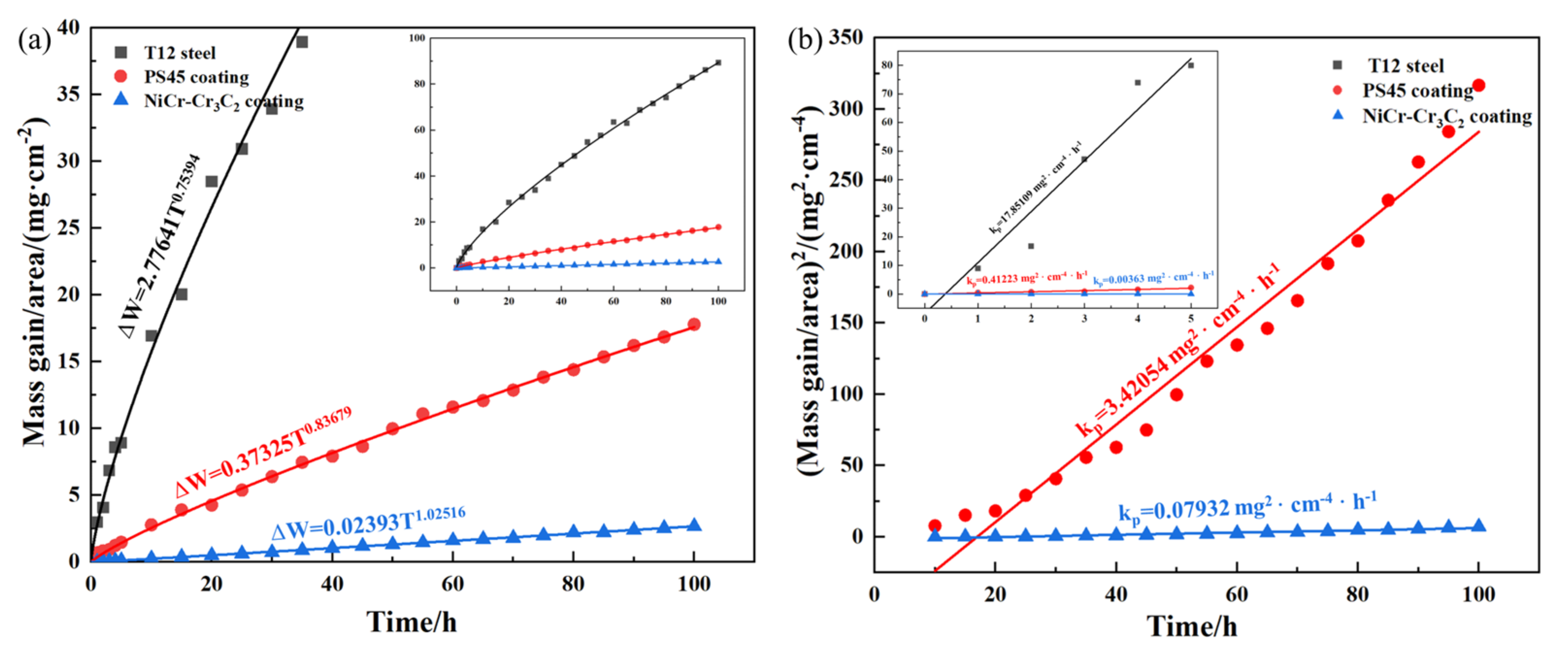
Figure 5a presents the high-temperature sulfate corrosion kinetics curves obtained from the substrate and two coated samples after 100 h of salt-coated heating at 750 °C. Evidently, the corrosion rates of both coatings are significantly lower than that of the substrate. The corrosion kinetics curves reveal two distinct stages: an initial rapid weight gain stage, followed by a stable slow weight gain stage. Nonlinear fitting was applied to the corrosion kinetics data using the mathematical model given in Equation (1):
Δ W = a T b
Here, ΔW represents the mass gain per unit area of the sample; T denotes the duration of high-temperature sulfate corrosion; a and b are constants. The fitted curves are shown in Figure 5a. The thermal corrosion kinetics curves of the coatings and the steel substrate generally follow a parabolic law. Following 100 h of high-temperature corrosion testing, the mass gain per unit area due to corrosion was measured at 89.4 mg/cm2 for the SA213-T12 steel substrate, 17.8 mg/cm2 for the PS45 coating, and 2.7 mg/cm2 for the NiCr–Cr3C2 coating.
Figure 5b shows the fitted parabolic rate constant curves for sulfate-induced hot corrosion at 750 °C. The square of the coating mass gain shows a near-linear relationship with corrosion time, confirming that the corrosion mass gain follows a parabolic law with time. The parabolic rate constants (kp) for the PS45 and NiCr–Cr3C2 coatings were determined to be 3.42054 mg2/(cm4·h) (R2 = 0.9531) and 0.07932 mg2/(cm4·h) (R2 = 0.9522), respectively. The significantly lower kp value of the NiCr–Cr3C2 coating indicates its slower corrosion rate and superior corrosion resistance.

3.3.2. Phase Composition and Surface Morphology Evolution of Coatings After High-Temperature Sulfate Corrosion

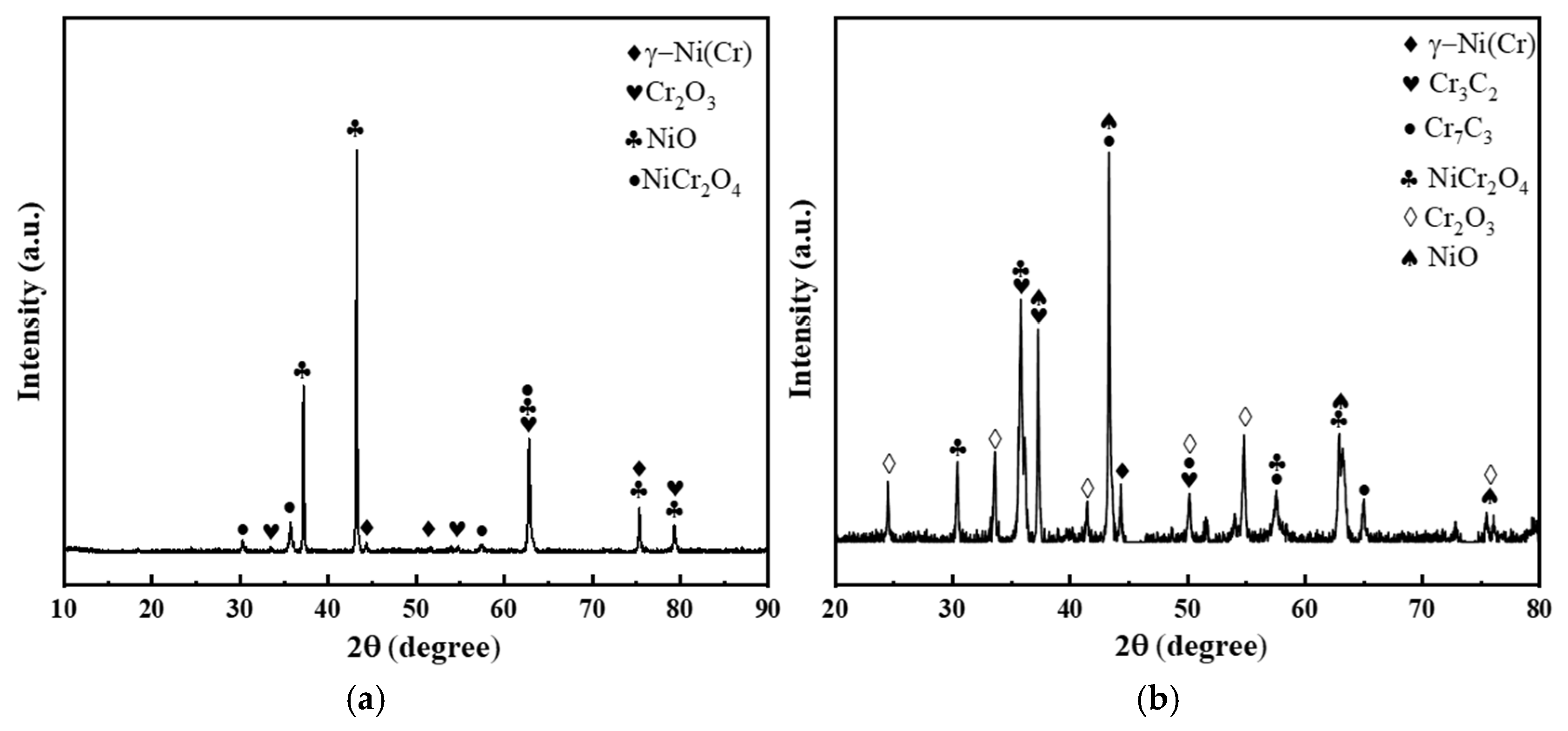
The XRD patterns of the two coatings after 100 h of sulfate corrosion at 750 °C are shown in Figure 6. After high-temperature sulfate corrosion, the PS45 coating showed a notable increase in the intensity of its oxide peaks (especially NiO, Cr2O3, and NiCr2O4). The analysis results of NiCr–Cr3C2 coating high-temperature sulfate corrosion products are shown in Figure 6b. The main phases identified included γ-Ni(Cr), Cr3C2, Cr7C3, NiCr2O4, Cr2O3 and NiO. By comparing the diffraction peak intensities, a significant increase in the intensity of NiCr2O4 peaks could be observed, indicating that the formation of NiCr2O4 is highly sensitive to the environmental temperature. Furthermore, the elevated temperature also promotes the growth of Cr7C3 phase peaks, suggesting that the thermal corrosion process weakened the mechanical properties of the coating.
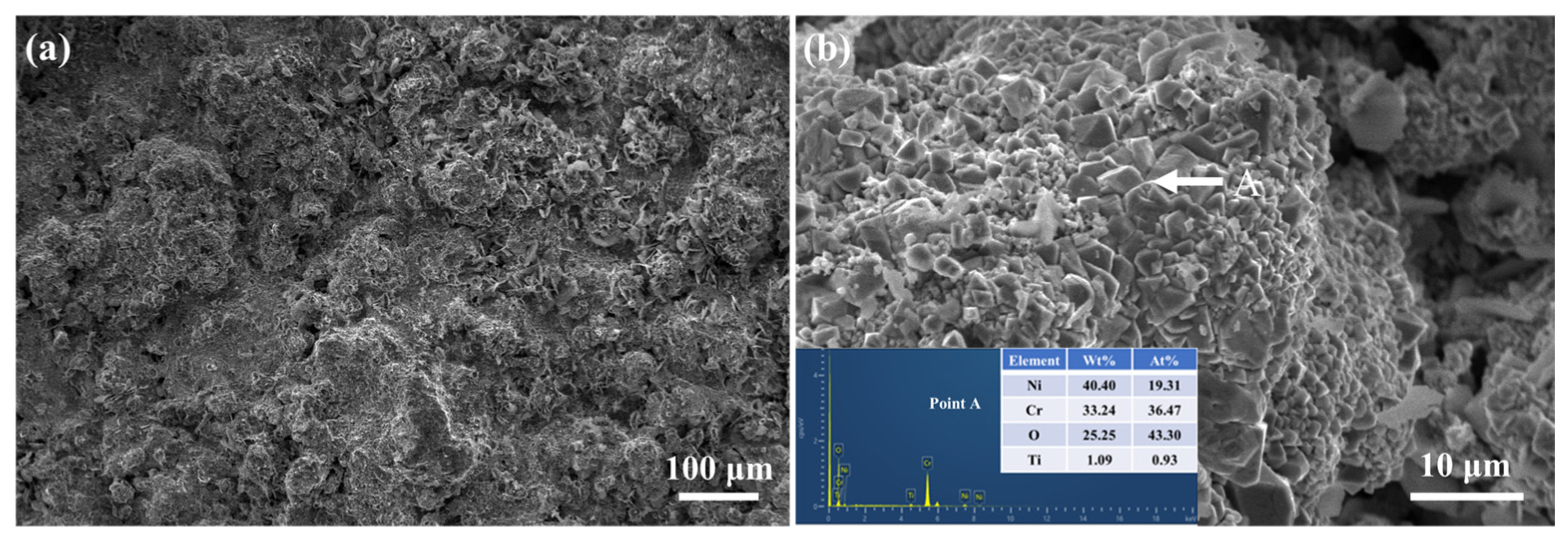
The surface morphology of the PS45 coating after 100 h of sulfate corrosion at 750 °C is shown in Figure 7. The coating surface was composed of rough nodular protrusions of varying sizes. Higher-magnification SEM imaging in Figure 7b revealed that a relatively thick oxide layer had formed on the coating, though it remained discontinuous due to the porous nature of the protruding structures. Fine-grained corrosion products with a spinel structure were also observed on the surface. Combined with EDS analysis at Point A and the phase composition results, the protruding oxide structures were determined to consist of Cr2O3 and NiO, while the spinel-structured phase was identified as NiCr2O4.
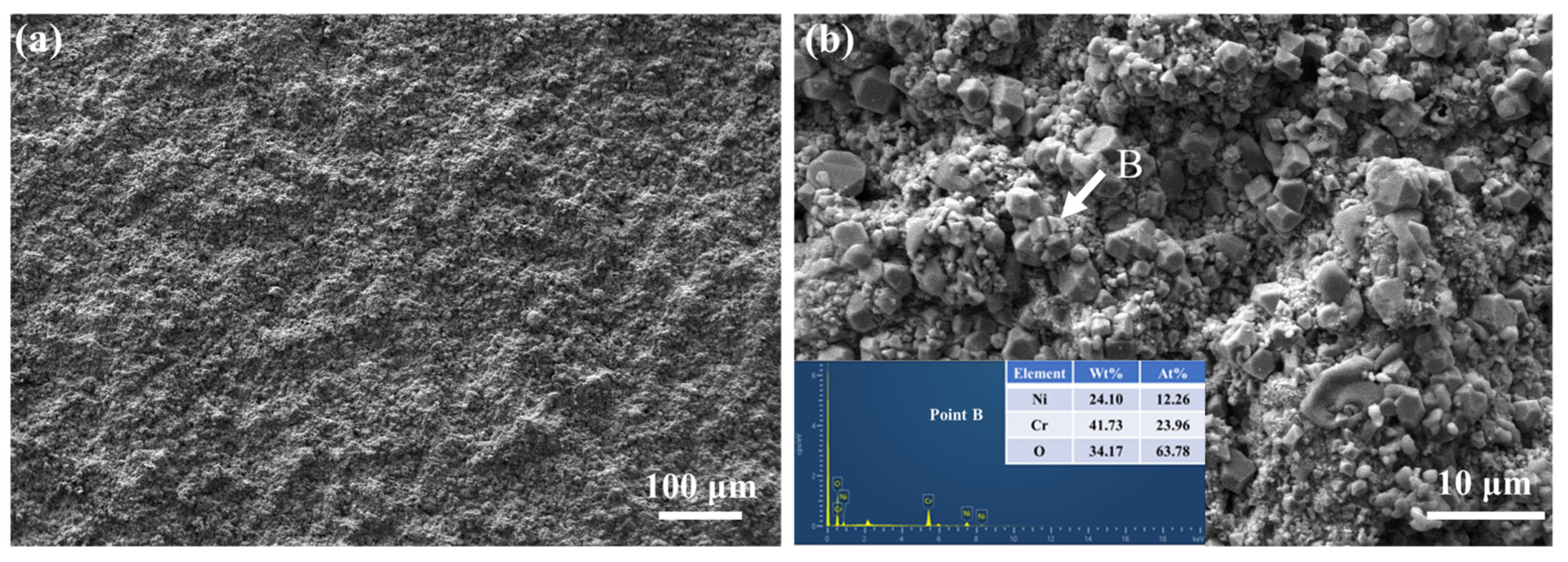
The surface morphology of the NiCr–Cr3C2 coating after 100 h of sulphuric acid corrosion at 750 °C is shown in Figure 8. As observed in Figure 8a, the coating surface remained intact but developed a fine-grained corrosion layer. Higher-magnification SEM imaging in Figure 8b revealed a substantial increase in granular corrosion products, forming a more continuous and dense oxide layer. This indicates that elevated temperature promoted rapid growth of oxides, resulting in a continuous and compact oxide film. EDS analysis confirmed that the corrosion products consisted predominantly of Cr and O with minor Ni, suggesting the formation of Cr2O3 and NiCr2O4 layers, consistent with XRD results. The presence of Cr2O3 and NiCr2O4 significantly enhances the coating’s resistance to high-temperature sulfate corrosion.

3.3.3. Mechanism of High-Temperature Sulfate Corrosion Resistance in NiCr–Cr3C2 Coatings

The mechanisms of hot corrosion have been extensively investigated by numerous scholars. Three widely recognized models are commonly used to describe the process: the sulfidation-oxidation model [33], the acid-base fluxing model [34], and the electrochemical model [35]. Among these, the acid-base fluxing model has gained broad acceptance. This model proposes that the protective oxide layer formed on the coating surface dissolves in the molten eutectic salt, gradually weakening its protective effect and thereby accelerating the hot corrosion process. The dissolution of the oxide layer generally occurs via acidic or basic fluxing, depending primarily on the acidity or alkalinity of the molten salt and the partial pressures of gases such as O2, SO2, and SO3. In this study, the oxides of Ni and Cr act as basic solutes. These basic solutes exhibit higher solubility at the oxide/molten salt interface than at the molten salt/gas interface. Consequently, the alloy undergoes basic fluxing, where dissolution occurs at the oxide/molten salt interface, followed by reprecipitation at the molten salt/gas interface. Chromium (Cr) plays a critical role in suppressing hot corrosion. Studies have shown that Cr also undergoes basic fluxing during hot corrosion [36], as described by the following equation:
Cr 2 O 3   +   Na 2 O   +   3 / 2 O 2 g   =   Na 2 Cr 2 O 7
It can be observed that Cr2O3 reacts to form Na2Cr2O7, and the dissolution process of Cr2O3 is significantly influenced by the local oxygen partial pressure (PO2). In any hot corrosion process, the oxide/molten salt interface exhibits higher reducibility compared to the molten salt/gas interface. Consequently, chromate reprecipitation occurs exclusively at the oxide/molten salt interface rather than within the eutectic melt, leading to the formation of a continuous and dense Cr2O3 layer. The high Cr content is one of the key factors contributing to the coating’s excellent hot corrosion resistance [22]. Additionally, to effectively resist hot corrosion damage, alloys or coatings tend to undergo selective oxidation [37], resulting in the formation of a single-phase oxide layer. Therefore, increasing the Cr content within a certain range can promote selective oxidation of the coating, thereby facilitating the formation of a dense Cr2O3 layer.
For Ni–Cr-based alloy coatings such as PS45 and NiCr–Cr3C2 coatings, the corrosion mass gain rate during the initial stage is primarily governed by atomic diffusion. Due to the higher diffusion rate of Ni compared to Cr, NiO grows more rapidly and tends to overgrow the Cr2O3 layer, resulting in a stratified oxide structure with distinct inner and outer layers [38]. Once a eutectic melt forms on the coating surface, SO42− is reduced at the oxide/molten salt interface:
2 SO 4 2   =   2 O 2 +   3 O 2 +   2 S
As the activity of O2− increases in the melt, Cr2O3 and NiO on the coating surface undergo basic fluxing by reacting with O2−, with Cr2O3 reacting preferentially over NiO. The reactions are expressed as follows:
Cr 2 O 3 +   2 O 2 +   3 / 2 O 2 =   Cr 2 O 4 2
NiO + O 2 =   NiO 2 2
These reactions reduce the activity of O2− in the melt. At the molten salt/air interface, however, the high oxygen partial pressure (PO2) prevents further reduction of SO42−. The decreased O2− activity lowers the solubility of NiO, causing the reaction in Equation (5) to reverse and resulting in the formation of a porous, non-protective NiO layer. Consequently, Cr2O3 continues to dissolve. When the solubility of Cr2O42− reaches saturation, the hot corrosion process ceases. At this stage, the coating is protected by a continuous and dense Cr2O3 layer. Compared to the PS45 coating, the NiCr–Cr3C2 coating fabricated by HVOF spraying contains a higher Cr content and exhibits a denser microstructure with lower porosity. These characteristics contribute to its superior resistance to high-temperature sulfate corrosion.

3.4. High-Temperature Tribological Properties of Coatings

3.4.1. High-Temperature Friction and Wear Behavior

Figure 9 presents the evolution of the friction coefficient over time for both the PS45 and NiCr–Cr3C2 coatings, tested at 750 °C, 0.105 m/s (Sliding speed), 10 N, and for 0.38 km (Sliding distance). Based on the evolution of the friction coefficient curves, the wear process can be divided into two distinct stages: an initial run-in stage and a subsequent steady-state wear stage. During wear, the actual contact area between the counterpart and the material is a critical factor influencing the friction force [39]. The friction coefficient curve of the PS45 coating exhibited significant fluctuations overall, and the coating entered the steady-state wear stage only after approximately 15 min, with the final friction coefficient stabilizing around 0.75. This behavior may be attributed to the rough surface and the presence of numerous pores in the coating, which increase its surface irregularity. In contrast, the NiCr–Cr3C2 coating reached the steady-state wear stage after about 5 min, after which the friction coefficient remained largely constant with minimal curve fluctuations, stabilizing around 0.4.
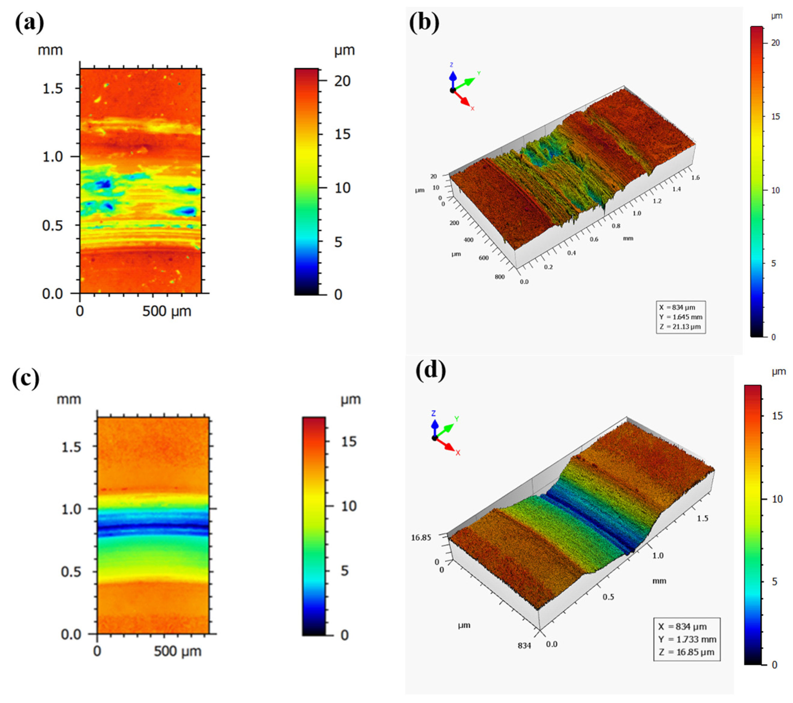
The three-dimensional morphology of wear traces on PS45 and NiCr–Cr3C2 coatings after 60 min of tribological testing at 750 °C under a 10 N load (see Figure 10). Under identical test parameters, the PS45 coating exhibited the largest wear scar width and depth, indicating the highest wear loss. Significant spalling pits were observed on the PS45 coating, which can be attributed to severe surface oxidation at high temperature. These oxides lack adequate support from the substrate, and under cyclic loading, pre-existing defects such as cracks propagate, leading to localized fracture and spalling pit formation. The NiCr–Cr3C2 coating exhibited a typical microstructure characterized by a homogeneous mixture of a metallic binder phase and hard ceramic phases, specifically a “soft metallic matrix with dispersed hard ceramic phases”. This structure contributes to its high strength, hardness, and wear resistance. However, due to partial decarburization occurring at high temperature, the overall mechanical properties of the NiCr–Cr3C2 coating are somewhat reduced.
Figure 11 shows the cross-sectional profile curves of the wear scars for the PS45 and NiCr–Cr3C2 coatings under the specified test conditions. The profile of the NiCr–Cr3C2 coating appears smoother, while that of the PS45 coating exhibits significant fluctuations. This difference is primarily attributed to the lower porosity and fewer defects in the HVOF-sprayed NiCr–Cr3C2 coating, which results in a more stable wear process. The measured wear scar width and maximum depth are 0.8 mm and 15 μm for the PS45 coating, and 0.7 mm and 12 μm for the NiCr–Cr3C2 coating, respectively. The larger wear scar dimensions of the PS45 coating confirm its higher wear loss and inferior wear resistance.
Following 60 min of wear testing at 750 °C under a 10 N load, the PS45 and NiCr–Cr3C2 coatings, respectively, exhibited wear volumes of 3.7 × 10⁻³ mm3 and 3.4 × 10⁻³ mm3. Although the NiCr–Cr3C2 coating exhibited triple the average microhardness of the PS45 coating, its wear volume remains comparatively high, being only marginally lower than that of PS45. This behavior is attributed to the wear of loose particles within the NiCr–Cr3C2 coating at elevated temperatures. During the wear process, the repeated impact and compressive forces from the counterpart ball cause the Cr3C2 particles to detach from the surface. These detached particles then act as abrasive agents, exacerbating the wear process.

3.4.2. High-Temperature Wear Resistance Mechanisms

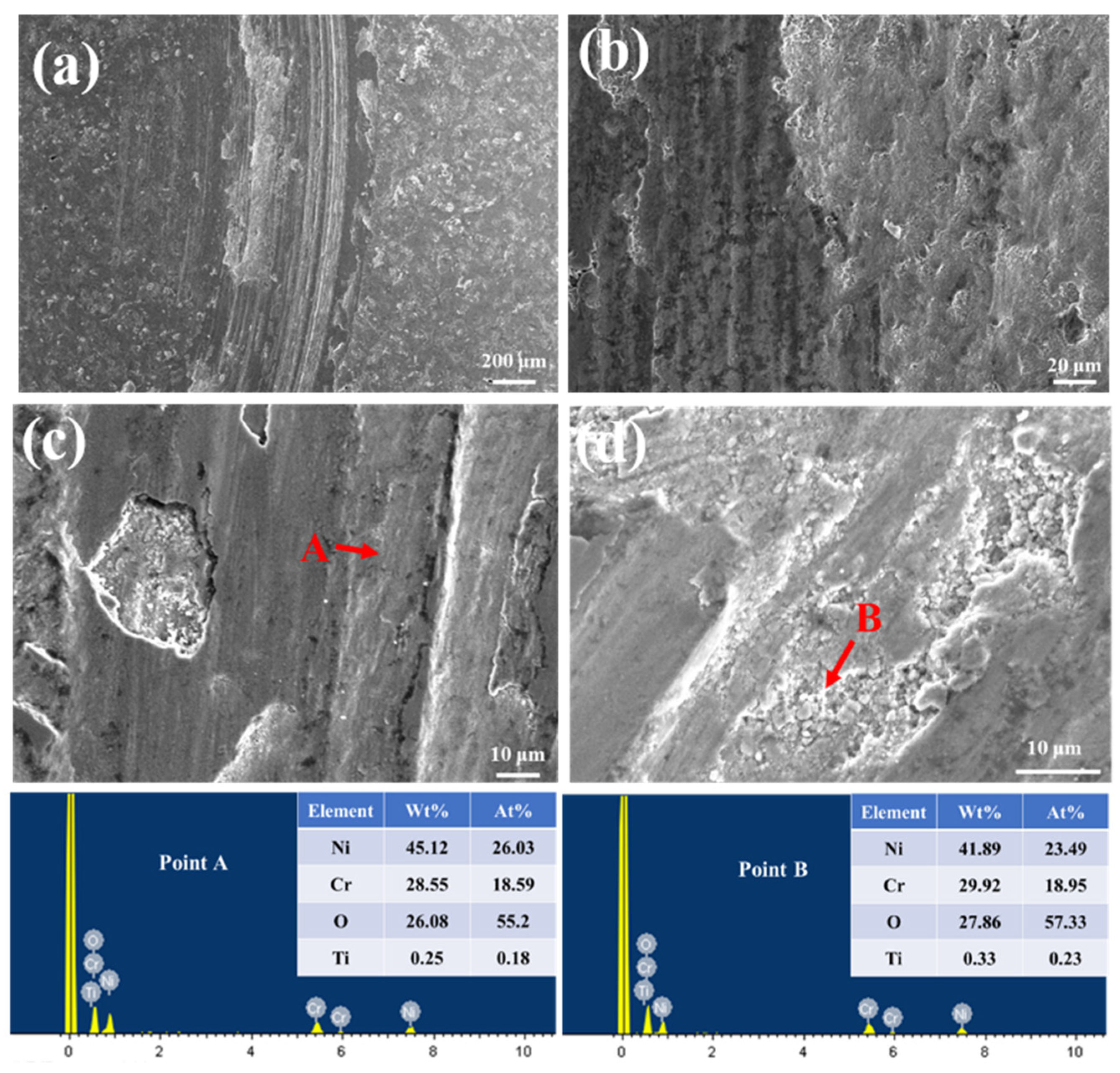
Figure 12 presents the wear scar morphology of the NiCr–Cr3C2 coating tested at 750 °C under 10 N for 60 min. The surface morphology appears relatively flat, whereas the PS45 coating exhibits more severe damage characterized by deep grooves, irregular protrusions, and pits. High-magnification images reveal that the dark bands on the NiCr–Cr3C2 coating consist of layered, dense debris (Figure 12c), while the PS45 coating shows areas of fine debris accumulation and spalling (Figure 13c). At high temperatures, the NiCr binder softens in both coatings. In NiCr–Cr3C2, loose particles function as abrasives, thereby promoting abrasive wear. In PS45, the softened binder fragments contribute to debris formation, alongside unmelted particles that enhance abrasion. Debris adhesion to the track or counter ball also leads to adhesive wear in both coatings. Therefore, it is necessary to improve the NiCr binder stability over 750 °C to enhance the high-temperature wear resistance of the coating. EDS analysis of NiCr–Cr3C2 reveals regions with low (Point A) and high (Point B) oxygen content, indicating mild and localized oxidation. PS45, however, exhibits consistently high oxygen levels, suggesting severe oxidative wear accompanied by cyclic spallation.
Together, both coatings experience abrasive, adhesive, and oxidative wear at 750 °C. The NiCr–Cr3C2 coating demonstrates flatter morphology with limited oxidation, while PS45 suffers from extensive oxidative damage and fatigue-induced spallation.

4. Conclusions

This study systematically investigated NiCr–Cr3C2 and PS45 coatings deposited on SA213-T12 steel substrates, revealing the underlying relationships between the coatings, microstructure, phase composition, porosity, mechanical properties, and their resistance to sulfate hot corrosion, as well as their high-temperature tribological performance. The conclusions are drawn as follows:
1.
The HVOF-sprayed NiCr–Cr3C2 coating exhibited a dense microstructure with low porosity (1.54%), high microhardness (965 HV0.3), and superior bonding strength (61.20 MPa), significantly outperforming the arc-sprayed PS45 coating.
2.
After 100 h of corrosion at 750 °C, the NiCr–Cr3C2 coating showed the lowest mass gain (2.7 mg/cm2): only 3.02% of the substrate and 15.17% of the PS45 coating. Its excellent corrosion resistance originated from the formation of a protective Cr2O3/NiCr2O4 layer via the basic fluxing mechanism, further enhanced by the high Cr content through selective oxidation, which effectively inhibited corrosive penetration.
3.
Both coatings experienced oxidative, abrasive, and adhesive wear at 750 °C. The NiCr–Cr3C2 coating demonstrated a lower stable friction coefficient (~0.4). However, the NiCr–Cr3C2 coating showed comparable wear volume to the PS45 coating due to the binder phase softening and subsequent hard phase detachment, which highlights the need for improved high-temperature binder stability.

Author Contributions

Conceptualization: H.Z., Z.Z., C.F., S.X. and D.S.; data curation: H.Z. and Z.Z.; formal analysis: H.Z., C.Z. and F.J.; funding acquisition: C.F., S.X. and D.S.; investigation: H.Z. and Z.Z.; methodology: H.Z., Z.Z., C.F., F.J., X.M. and Y.C.; project administration: C.F. and S.X.; supervision: C.F., D.S. and S.X.; Validation: Y.C. and Y.N.; visualization: C.Z., F.J. and Y.N.; writing—original draft: H.Z.; writing—review and editing: C.F., S.X. and D.S. All authors have read and agreed to the published version of the manuscript.

Funding

China Power International Holding Ltd. (ZGDL-KJ-2022-024) and the Fundamental Research Funds for the Central Universities (B250201220).

Institutional Review Board Statement

Not applicable.

Informed Consent Statement

Not applicable.

Data Availability Statement

Data are contained within the article.

Conflicts of Interest

Authors Cheng Zhou, Fangzhou Jin and Yongfeng Cai were employed by Wuhu Power Generation Co., Ltd. Authors Yifan Ni, Xinmin Ma and Chenghao Fan were employed by Shanghai Power Equipment Research Institute. The authors declare that this study received funding from China Power International Holding Ltd. The funder was not involved in the study design, collection, analysis, interpretation of data, the writing of this article or the decision to submit it for publication.

References

  1. Chen, Z.; Li, Z.; Zhu, Q.; Jing, J. Gas/particle flow and combustion characteristics and NOx emissions of a new swirl coal burner. Energy 2011, 36, 709–723. [Google Scholar] [CrossRef]
  2. Liu, G.; Zheng, L.; Gao, L.; Zhang, H.; Peng, Z. The characterization of coal quality from the Jining coalfield. Energy 2005, 30, 1903–1914. [Google Scholar] [CrossRef]
  3. You, C.; Xu, X. Coal combustion and its pollution control in China. Energy 2010, 35, 4467–4472. [Google Scholar] [CrossRef]
  4. Le Bris, T.; Cadavid, F.; Caillat, S.; Pietrzyk, S.; Blondin, J.; Baudoin, B. Coal combustion modelling of large power plant, for NOx abatement. Fuel 2007, 86, 2213–2220. [Google Scholar] [CrossRef]
  5. Dong, J.; Fan, H.; Wu, X.; Zhou, T.; Zhang, J.; Zhang, Z. Study on the effect of flame offset on water wall tube temperature in 600 °C and 700 °C ultra-supercritical boiler. Combust. Sci. Technol. 2018, 191, 472–490. [Google Scholar] [CrossRef]
  6. Song, T.; Wang, Z. Research Progress on High-temperature Oxidation of Austenitic Stainless Steel for Ultra-superCritical Boilers. IOP Conf. Ser. Mater. Sci. Eng. 2020, 735, 012008. [Google Scholar] [CrossRef]
  7. Phongphiphat, A.; Ryu, C.; Yang, Y.B.; Finney, K.N.; Leyland, A.; Sharifi, V.N.; Swithenbank, J. Investigation into high-temperature corrosion in a large-scale municipal waste-to-energy plant. Corros. Sci. 2010, 52, 3861–3874. [Google Scholar] [CrossRef]
  8. Kaur, M.; Singh, H.; Prakash, S. Surface engineering analysis of detonation-gun sprayed Cr3C2–NiCr coating under high-temperature oxidation and oxidation–erosion environments. Surf. Coat. Technol. 2011, 206, 530–541. [Google Scholar] [CrossRef]
  9. Kung, S.C. Further Understanding of Furnace Wall Corrosion in Coal-Fired Boilers. Corrosion 2013, 70, 749–763. [Google Scholar] [CrossRef]
  10. Reiche, M.; Grahl, S.; Beckmann, M. Advanced monitoring of the fouling process on water walls. Fuel 2018, 216, 436–444. [Google Scholar] [CrossRef]
  11. Wang, S.; Xin, Y. Anaysis on High-temperature Corrosion and Erosion of Water-Cooler Tube. Corros. Sci. Prot. Technol. 2010, 22, 243–246. [Google Scholar]
  12. Skrifvars, B.-J.; Backman, R.; Hupa, M.; Salmenoja, K.; Vakkilainen, E. Corrosion of superheater steel materials under alkali salt deposits Part 1: The effect of salt deposit composition and temperature. Corros. Sci. 2008, 50, 1274–1282. [Google Scholar] [CrossRef]
  13. Wang, Z.; Zhang, X.; Cheng, J.; Lin, J.; Zhou, Z. Cavitation Erosion Resistance of Fe-Based Amorphous/Nanocrystal Coatings Prepared by High-Velocity Arc Spraying. J. Therm. Spray Technol. 2014, 23, 742–749. [Google Scholar] [CrossRef]
  14. Cheng, J.; Liu, D.; Liang, X.; Chen, Y. Wear Behaviors of Arc-Sprayed FeBSiNb Amorphous Coatings. Tribol. Lett. 2015, 60, 22. [Google Scholar] [CrossRef]
  15. Chen, P.H.; Liu, Z.L.; Li, R.Q.; Qiu, C.J.; Li, X.Q. Thermal-sprayed coating of optimally mixed ceramic powders on stainless steel with enhanced corrosion resistance. J. Iron. Steel Res. Int. 2018, 25, 207–212. [Google Scholar] [CrossRef]
  16. Yuan, Z.F.; Xie, S.S.; Yu, X.T.; Liu, J.; Du, P.; Li, Z.H. Wear-resistant coating spraying technique for wear-proofing cover of coke dry quenching furnace. J. Iron Steel Res. Int. 2018, 26, 123–129. [Google Scholar] [CrossRef]
  17. He, D.; Dong, N.; Jiang, J. Corrosion Behavior of Arc Sprayed Nickel-Base Coatings. J. Therm. Spray Technol. 2007, 16, 850–856. [Google Scholar] [CrossRef]
  18. Ji, G.C.; Li, C.J.; Wang, Y.Y.; Li, W.Y. Erosion performance of HVOF-sprayed Cr3C2-NiCr coatings. J. Therm. Spray Technol. 2007, 16, 557–565. [Google Scholar] [CrossRef]
  19. Matthews, S.; James, B.; Hyland, M. The Effect of Heat Treatment on the Oxidation Mechanism of Blended Powder Cr3C2-NiCr Coatings. J. Therm. Spray Technol. 2009, 19, 119–127. [Google Scholar] [CrossRef]
  20. Ghosh, D.; Mitra, S.K. Plasma sprayed Cr3C2–Ni–Cr coating for oxidation protection of 2·25Cr–1Mo steel. Surf. Eng. 2014, 31, 342–348. [Google Scholar] [CrossRef]
  21. Hussain, T.; Dudziak, T.; Simms, N.J.; Nicholls, J.R. Fireside corrosion behavior of HVOF and plasma-sprayed coatings in advanced coal/biomass co-fired power plants. J. Therm. Spray Technol. 2013, 22, 797–807. [Google Scholar] [CrossRef]
  22. Yadav, A.S.; Mishra, S.B. Comparative erosion performance of HVOF and LVOF sprayed NiCrSiBCFe-WC-Co coating. Surf. Eng. 2024, 40, 575–590. [Google Scholar] [CrossRef]
  23. Sudhakara, D.; Jeyasimmana, D.; Duraiselvamb, M. Dry Sliding Wear Behavior of Cr3C2-NiCr Coating on Austenitic Stainless Steel. Int. J. Core Eng. Manag. 2015, 1, 215–225. [Google Scholar]
  24. Chatha, S.S.; Sidhu, H.S.; Sidhu, B.S. Characterisation and corrosion-erosion behaviour of carbide based thermal spray coatings. J. Miner. Mater. Charact. Eng. 2012, 11, 569–586. [Google Scholar] [CrossRef]
  25. Mehta, J.; Mittal, V.K.; Gupta, P. Role of thermal spray coatings on wear, erosion and corrosion behavior: A review. J. Appl. Sci. Eng. 2017, 20, 445–452. [Google Scholar]
  26. Schubert, J.; Česánek, Z.; Bláhová, O. Mechanical Properties of HVOF Sprayed CrC-NiCr Coating Exposed to Hot Corrosion Environment. Key Eng. Mater. 2018, 784, 141–146. [Google Scholar] [CrossRef]
  27. Chatha, S.S.; Sidhu, H.S.; Sidhu, B.S. High temperature hot corrosion behaviour of NiCr and Cr3C2–NiCr coatings on T91 boiler steel in an aggressive environment at 750 °C. Surf. Coat. Technol. 2012, 206, 3839–3850. [Google Scholar] [CrossRef]
  28. Oksa, M.; Auerkari, P.; Salonen, J.; Varis, T. Nickel-based HVOF coatings promoting high temperature corrosion resistance of biomass-fired power plant boilers. Fuel Process. Technol. 2014, 125, 236–245. [Google Scholar] [CrossRef]
  29. Somasundaram, B.; Kadoli, R.; Ramesh, M. Evaluation of Thermocyclic Oxidation Behavior of HVOF Sprayed (Cr3C2-35% NiCr) + 5% Si Coatings on Boiler Tube Steels. Procedia Mater. Sci. 2014, 5, 398–407. [Google Scholar] [CrossRef]
  30. Manjunatha, K.; Giridhara, G.; Shivalingappa, D. High temperature erosion behaviour of high-velocity oxy-fuel sprayed CNT/NiCr-Cr3C2 composite coatings. Surf. Coat. Technol. 2022, 448, 128900. [Google Scholar]
  31. Gok, K.; Ada, H.D.; Kilicaslan, N.; Gok, A. A Review of CFD Modeling of Erosion-induced Corrosion Formation in Water Jets Using FEA. J. Mech. Mater. Mech. Res. 2023, 6, 14–22. [Google Scholar] [CrossRef]
  32. ISO 14916:2017; Thermal Spraying—Determination of Tensile Adhesive Strength. ISO: Geneva, Switzerland, 2017.
  33. Simons, E.L.; Browning, G.V.; Liebhafsky, H.A. Sodium Sulfate in Gas Turbines. Corrosion 1955, 11, 17–26. [Google Scholar] [CrossRef]
  34. Bornstein, N.S.; DeCrescente, M.A. The role of sodium in the accelerated oxidation phenomenon termed sulfidation. Met. Trans. 1971, 2, 2875–2883. [Google Scholar] [CrossRef]
  35. Shores, D.A.; Fang, W. Transport of Oxidant in Molten Na2SO4 in O2-SO2-SO3 Environments. J. Electrochem. Soc. 1981, 128, 346–348. [Google Scholar] [CrossRef]
  36. Otsuka, N.; Rapp, R.A. Hot Corrosion of Preoxidized Ni by a Thin Fused Na2SO4 Film at 900 °C. J. Electrochem. Soc. 1990, 137, 46. [Google Scholar] [CrossRef]
  37. Ding, Y.; Hussain, T.; Mccartney, D.G. High-temperature oxidation of HVOF thermally sprayed NiCr–Cr3C2 coatings: Micro-structure and kinetics. J. Mater. Sci. 2015, 50, 6808–6821. [Google Scholar] [CrossRef]
  38. Bala, N.; Singh, H.; Prakash, S. Accelerated hot corrosion studies of cold spray Ni–50Cr coating on boiler steels. Mater. Des. 2010, 31, 244–253. [Google Scholar] [CrossRef]
  39. Berger, L.M.; Woydt, M.; Zimmermann, S.; Keller, H.; Schwier, G.; Enžl, R.; Thiele, S. Tribological behavior of HVOF-sprayed Cr3C2-NiCr and TiC-based coatings under high-temperature dry sliding conditions. In Proceedings of the International Thermal Spray Conference, Osaka, Japan, 10–12 May 2004; pp. 468–477. [Google Scholar]
Figure 1. (a,b) Microstructural morphology of NiCr-Cr3C2 powders.
Coatings 15 01152 g001
Figure 2. SEM surface morphologies of coatings. (a,b) PS45 coating; (c,d) NiCr-Cr3C2 coating.
Coatings 15 01152 g002
Figure 3. Microstructure morphology and phase composition of coatings. (a,c) PS45 coating; (b,d) NiCr-Cr3C2 coating.
Coatings 15 01152 g003
Figure 4. Microhardness distribution of coatings and substrate.
Coatings 15 01152 g004
Figure 5. High-temperature oxidative corrosion kinetic curves of coatings. (a) Tested and fitted oxidative corrosion kinetic curves; (b) fitting curve of coating weight change/area square and oxidation time.
Coatings 15 01152 g005
Figure 6. XRD pattern of a coating after a high-temperature sulfate corrosion test. (a) PS45 coating; (b) NiCr-Cr3C2 coating.
Coatings 15 01152 g006
Figure 7. Surface morphology of PS45 coating after hot corrosion at 750 °C for 100 h. (a) low and (b) high magnification.
Coatings 15 01152 g007
Figure 8. Surface morphology of NiCr-Cr3C2 coating after hot corrosion at 750 °C for 100 h. (a) low and (b) high magnification.
Coatings 15 01152 g008
Figure 9. Variation in coating friction coefficient with wear time.
Coatings 15 01152 g009
Figure 10. Three-dimensional topographies of the worn track of coatings. (a,b) PS45 coating; (c,d) NiCr-Cr3C2 coating.
Coatings 15 01152 g010
Figure 11. Contour of the worn track of coatings. (a) PS45 coating; (b) NiCr-Cr3C2 coating.
Coatings 15 01152 g011
Figure 12. Microscopic morphology of the worn track and EDS analysis results of the PS45 coating. (a) low and (bd) high magnification.
Coatings 15 01152 g012
Figure 13. Microscopic morphology of the worn track and EDS analysis results of the NiCr-Cr3C2 coating. (a) low and (bd) high magnification.
Coatings 15 01152 g013
Table 1. Chemical composition of NiCr-Cr3C2 powders (wt.%).
ElementNiCrC
Content16.3272.2811.39
Table 2. Chemical composition of PS45 core wires (wt.%).
ElementNiCrTiAlFe
Content57.2840.751.000.160.10
Table 3. PS45 coating spraying process parameters.
Spray ParametersPS45 Coating
Arc voltage (V)24
Current (A)150
Air pressure (kPa)600
Spray distance (mm)150
Table 4. NiCr-Cr3C2 coating spraying process parameters.
Spray ParametersNiCr-Cr3C2 Coating
Carrier gas flow rate(gph)26
Kerosene flow rate(gph)3
Oxygen flow rate (scfh)2000
Powder feed rate (rpm)3
Spray distance (mm)350
Gun traverse speed (mm·s−1)200
Disclaimer/Publisher’s Note: The statements, opinions and data contained in all publications are solely those of the individual author(s) and contributor(s) and not of MDPI and/or the editor(s). MDPI and/or the editor(s) disclaim responsibility for any injury to people or property resulting from any ideas, methods, instructions or products referred to in the content.