Article

The Effect of Current Density and Cathode Position on the Corrosion Resistance and Thermal Emission Properties of Nickel Electroplated Layers on Brass Surfaces

1
Key Laboratory of Green Fabrication and Surface Technology of Advanced Metal Materials (Anhui University of Technology), Ministry of Education, Maanshan 243002, China
2
School of Physics and Electronic Technology, Liaoning Normal University, Dalian 116029, China
3
School of Integrated Circuits, Dalian University of Technology, Dalian 116620, China
*
Author to whom correspondence should be addressed.
Coatings 2025, 15(11), 1276; https://doi.org/10.3390/coatings15111276
Submission received: 5 September 2025 / Revised: 11 October 2025 / Accepted: 23 October 2025 / Published: 3 November 2025

Abstract

Brass components are widely used in heat dissipation and thermal emission devices due to their high thermal conductivity and ease of processing. However, these applications demand good thermal oxidation resistance, high emissivity, and excellent corrosion resistance. In this study, nickel coatings were deposited on brass substrates by direct current electroplating, and the effects of current density and cathode configuration on the microstructure, emissivity, and corrosion resistance of the coatings were systematically investigated. The results show that the emissivity of the coatings first increased and then decreased with increasing current density. Optimal performance was achieved when the cathode and anode were positioned perpendicular to the horizontal plane at a current density of 3.0 A·dm−2. Under these conditions, the coatings exhibited a smooth, uniform, and dense microstructure, with evenly distributed metallic grains. Electrochemical polarization and impedance measurements further confirmed the superior corrosion resistance of this coating, with a minimum corrosion current density of 0.259 μA·cm−2, a maximum polarization resistance of 6381.55 Ω·cm2, and a minimum corrosion rate of 0.023 mm/a. These findings demonstrate a simple and effective approach to enhancing both the emissivity and corrosion resistance of brass substrates, offering practical value for thermal management applications.

1. Introduction

Brass possesses excellent electrical and thermal conductivity, elasticity, and mechanical strength, while also offering favorable formability, weldability, and machinability [1]. These properties make it widely applicable in industries such as sanitary ware, electrical and electronic components [2], and equipment manufacturing [3]. In particular, components such as heat sinks and gas stove nozzles require brass parts with efficient heat dissipation, high emissivity, and strong corrosion resistance. However, brass is inherently prone to oxidation, mechanical damage, and corrosion, necessitating surface modification. Nickel electroplating has been widely employed to address these challenges, as it not only mitigates surface oxidation but also enhances wear resistance, corrosion resistance, electrical conductivity, and overall durability.
Since the early 20th century, brass-based nickel electroplating processes have been continuously developed and are now extensively applied in industrial production [4,5,6]. Nickel coatings obtained by direct-current (DC) electroplating exhibit excellent corrosion resistance, electrical conductivity, thermal emissivity, and esthetic appearance [7,8]. Among these, corrosion resistance and emissivity are considered the most critical properties. Emissivity directly governs the efficiency of thermal radiation and dissipation, with higher emissivity leading to superior heat dissipation performance. Corrosion resistance, on the other hand, is largely determined by factors such as material composition, chemical stability, and microstructural characteristics, and dictates the service lifetime of the plated components [9,10]. Considerable efforts have been dedicated to optimizing brass-based electroplated nickel coatings by controlling key deposition parameters such as nickel ion concentration [11], plating bath temperature, and current density [12]. These studies aim to obtain coatings with improved homogeneity, compactness, adhesion, and corrosion resistance. For instance, Li et al. [13] reported that Ni–Fe alloy coatings deposited at 4–6 A·dm−2 exhibited the lowest corrosion rates. In another study, Li et al. [14] demonstrated that nickel coatings on brass heat exchangers possess excellent high-temperature oxidation resistance, enabling applications in aero-engine blades, nuclear reactors, and other energy conversion equipment. Their work further revealed that deposition time strongly influences the oxidation resistance, hardness, and wear resistance of nickel coatings, leading to improved adhesion and corrosion resistance. Somasundaram et al. [15] employed pulsed electrochemical deposition to fabricate high-emissivity nickel coatings on brass substrates and systematically examined the effects of plating solution composition, temperature, pH, current density, and deposition time. Their results showed that the controlled addition of zinc ions significantly enhanced coating emissivity. Furthermore, Stern et al. [16] introduced the Stern–Geary equation to predict the corrosion resistance of electroplated coatings by fitting polarization curves, providing a theoretical framework for process optimization. Despite extensive research on the effect of current density on corrosion resistance, the combined influence of current density and cathode-anode configuration has received far less attention. Addressing these overlooked factors is crucial, as they directly determine the thermal radiation efficiency and structural integrity of electroplated nickel coatings, thereby filling an important gap in current electroplating studies.
In this work, nickel coatings were electrochemically deposited onto brass substrates to investigate the effects of current density and electrode configuration. Current density was first optimized, and the electrodes were arranged perpendicular to the horizontal plane to ensure parallel and equidistant electric field distribution, thereby enhancing coating performance. The influence of these parameters on coating morphology, emissivity, and corrosion resistance was systematically evaluated using an IR-2 dual-band emissivity meter, optical microscopy, scanning electron microscopy, and electrochemical testing. The results demonstrate that optimized nickel plating on brass yields coatings with superior corrosion resistance and enhanced thermal emissivity, providing a reliable foundation for practical applications.

2. Experimental

2.1. Experiment Materials and Preparation

The plating process was executed utilizing a Watts-type nickel plating solution, comprising nickel sulfate hexahydrate (NiSO4·6H2O) at a concentration of 190 g/L, nickel chloride hexahydrate (NiCl2·6H2O) at a concentration of 40 g/L, boric acid (H3BO3) at a concentration of 35 g/L, and sodium dodecyl sulfate at a concentration of 0.5 g/L. Among them, sodium dodecyl sulfate (SDS) acts as a surfactant/wetting agent and dispersant. It can reduce surface tension, improve the wettability and coverage of the plating bath, inhibit the formation of coarse crystal nuclei, and enhance the compactness and brightness of the nickel coating.
The size of the brass sheet is Φ30 mm and the thickness is 3 mm, and it is pre-treated according to the following process: sandpaper grinding → sample polishing → ultrasonic cleaning → alcohol cleaning → blow-drying.

2.2. Coating Preparation

In this paper, the current density is first optimized and then the plating performance obtained by different cathode and anode placements is compared. The experimental parameters delineated in Table 1 were utilized to investigate the impact of varying current densities on the plating performance. The plating solution was stirred throughout the experiment using a magnetic stirrer. Traditional Watts-type nickel plating requires heating to above 40 °C to improve deposition efficiency, but its energy consumption accounts for a high proportion (approximately 15%–20% of the total electroplating cost). This study aims to verify the feasibility of preparing qualified coatings by optimizing the composition of the plating solution under room temperature conditions, so room temperature (RT) was selected as the experimental temperature. Bath temperature is low and simplex, which is a limitation of this work. In our future works, heated bath will be used to obtain high-quality coatings and to investigate the effect on coating microstructure.
In light of the findings from the current density exploration experiment, it was determined that an optimal current density of 3.0 A·dm−2 would be utilized to investigate the effect of varying cathode and anode placements on the coating performance. The significance of exploring electrode configurations (vertical/horizontal) is to investigate the indirect effect of gravity on the mass transfer process of the plating solution. In the horizontal configuration, the H2 bubbles precipitated on the cathode surface tend to be retained, hindering the diffusion of Ni2+; in contrast, the vertical configuration is more conducive to the detachment of bubbles. Although neither configuration changes the total deposition amount, they may affect the uniformity of the coating morphology. The experiment was divided into two groups. The first group was placed in the parallel horizontal plane of the cathode and anode, as shown in Figure 1a. The second group was the anode and cathode positioned perpendicular to the horizontal plane, see Figure 1b. The cathode-to-anode area ratio was determined to be 1: (1.25–1.45). The experimental parameters are delineated in Table 2.
All current densities described in this paper refer to the deposition process parameters during electroplating, which are used to control the formation rate and thickness of the coating. The corrosion performance tests were not conducted under a constant current; instead, the corrosion current density (Icorr) was obtained by fitting potentiodynamic polarization curves. Therefore, the Icorr reported in this paper is an electrochemical kinetic parameter and does not represent the applied test current during the experiment.

2.3. Morphology Characterization and Performance Assessment

The initial observation of the plating was conducted using a Nikon Eclipse E200 optical microscope (Nikon Precision Co., Ltd., Shanghai, China). Detailed surface morphology was observed using a TM3030 electron microscope from Hitachi (Hitachi Scientific Instruments, Beijing, China). The coating thickness was determined using a LS225 Eddy current thickness gauge, and provided in Table 1 and Table 2. The emissivity of the samples was measured using an IR-2 dual-band emissivity meter with a test band of 8–14 μm. Each sample was measured five times, and the average value was taken to analyze the thermal emission properties of the coatings.
The corrosion resistance of the plating was evaluated using an electrochemical workstation (model CHI660e, CH Instruments, Inc., Shanghai, China). In this paper, a three-electrode electrochemical system was utilized, comprising a saturated calomel electrode as the reference electrode, a 213 platinum electrode (Gooss Union, Inc., Tianjin, China) as the counter electrode, and a plated sample as the working electrode. An effective test area of 1 cm2 was selected and the rest was sealed with insulating tape. The corrosion resistance of the samples was evaluated in a 3.5% NaCl solution by employing Tafel curves and electrochemical impedance spectroscopy (EIS). Prior to the test, the sample was stabilized at the open-circuit potential (OCP) for 10 min. The scanning range of the polarization curve was OCP ± 0.3 V (with a total scanning amplitude of 0.6 V), and the scanning rate was 10 mV·s−1. The frequency range of the electrochemical impedance spectroscopy (EIS) is 105–10−2 Hz.
In the equivalent circuit model, a Constant Phase Element (CPE) is used to characterize the non-ideality of the interfacial capacitance. It should be specifically noted that no independent Warburg element is introduced into the equivalent circuit in this paper. The exponent n of the CPE is employed to reflect the degree of deviation at the interface: when n is close to 1, the CPE approaches an ideal capacitor; when n is close to 0.5, its electrochemical behavior may exhibit diffusion-related characteristics.

3. Results and Discussion

3.1. Surface Morphology Analysis

Figure 2 shows the photographs and optical micrographs of Ni coatings obtained at varying current densities. It can be seen that as the current density varies in the range between 2.5 A·dm−2 and 3.0 A·dm−2, the plating layer gradually becomes thicker, and the surface of the coating is gradually uniform and dense, and has a nickel metallic luster. This phenomenon can be attributed to the enhancement of the current density, which results in the transformation of the original uneven and thin plating layer into a uniform and dense structure. As the current density increases to 5.0 A·dm−2, more pores and pits appear on the surface of the coating. This is because the current density increases and the deposition speed becomes faster, which makes the nickel ions unevenly distributed on the surface of the coating, so more pores appear on the surface of the coating. At the same time, due to the stronger cathode polarization effect, the hydrogen evolution reaction on the coating surface is aggravated [17], resulting in more hydrogen bubbles, resulting in an increase in pores, and resulting in the binding force between the nickel plating and the brass sample becoming weaker. When the current density reaches 7.0 A·dm−2, cracks appear on the surface of the coating and local areas are broken and rolled up. When the current density increases to the threshold, the deposition speed intensifies, resulting in the extensive accumulation of nickel ions, while huge internal stress on the surface of the plating causes cracks and even peeling off.
As demonstrated above, the optimum value of current density is determined to be 3.0 A·dm−2. Utilizing the aforementioned current density and modifying the cathode placement to be perpendicular to the horizontal, (3.0 A·dm−2)* plating was obtained. As demonstrated in Figure 2e, the surface of the plating layer exhibits a distinct nickel metal luster, characterized by a smooth and dense consistency. The presence of air holes is imperceptible to the naked eye, and the irregular arc pattern is notably shallow. The rationale behind this phenomenon pertains to the utilization of an optimized current density for this specific group of plating processes. Under horizontal placement, the hydrogen gas evolved on the electrode surface and the convection of the electrolyte are restricted, making bubbles prone to stagnation in local areas, which leads to uneven local deposition or pore formation. In contrast, under vertical placement, bubbles are more likely to detach along the vertical direction due to buoyancy, and the electrolyte exchange is more sufficient. This weakens the bubble shielding effect and local ion depletion, thereby improving deposition uniformity. The strategic placement of the cathode and anode can facilitate the uniform distribution of the electric field across the surface of the cathode, thereby ensuring the most uniform and dense surface for the plating process [18].
To further verify this macroscopic characteristic, Figure 3 presents the SEM microstructures of the same group of samples: (a) the ×1000 magnification image confirms that the coating is overall dense and free of defects, while (b) the ×4000 high-magnification image further reveals the uniform distribution of grain sizes. The microstructural features can be attributed to the synergistic regulation of three aspects: the optimized current density ensures the steady-state growth of grains, the effective diffusion of ions in the electroplating bath, and the precise control of flow rate. These factors collectively enable the efficient and uniform deposition of nickel on the substrate surface. These factors collectively facilitate the enhanced deposition of nickel metal onto the surface of the plating layer, thereby ensuring the desired quality and consistency of the deposit. However, some pinholes and crystallization anomalies can be observed in the local areas, as illustrated in the red box in Figure 3a. Upon magnification of the abnormal crystallization area, rounded knot-like protrusions become apparent, as illustrated in Figure 3b. The underlying cause of this defect is attributed to abnormal grain growth, resulting from abnormal nucleation. In conclusion, the plated Ni coating prepared at a current density of 3.0 A·dm−2, with the cathode placed both vertically and horizontally, exhibits the optimum surface morphology.

3.2. Emissivity of the Coatings

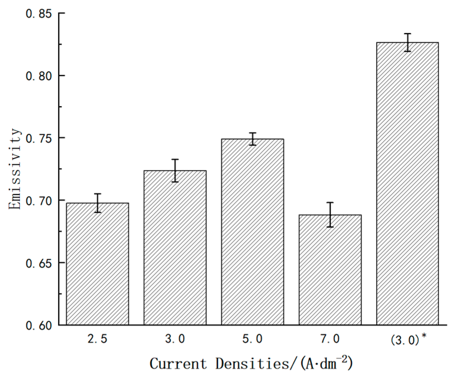
The emissivity data for each group of samples is presented in Figure 4. It is evident from this figure that, in the comparison of the four groups of coatings prepared using cathodes placed parallel to the horizontal plane, the emissivity first increases and then decreases as the current density increases. The maximum emissivity of the plated layers was observed at a current density of 5.0 A·dm−2, while the minimum was recorded at 7.0 A·dm−2. The emissivity of the (3.0 A·dm−2)* plated layer prepared by using the cathode and anode placed vertically in the horizontal plane was found to be the largest among the five groups of samples.
The emissivity of a material is usually positively correlated with its surface roughness. As shown in Figure 2, when the current density increases from 2.5 A·dm−2 to 5.0 A·dm−2, the number of surface defects (such as holes and cracks) in the coating increases, and the macroscopic morphology shows a significant increase in roughness (Figure 2a–d). At a low current density of 2.5 A·dm−2, the slow deposition rate results in an overly thin (~7.1 μm) and non-dense coating (Figure 2a), which fails to completely cover the brass substrate (local exposed areas are indicated by arrows), thus leading to low emissivity. With the increase in current density, surface irregularity enhances, and the multiple scattering effect of the rough surface improves the absorption efficiency of incident radiation. According to Kirchhoff’s law of thermal radiation, under thermal equilibrium, the absorptivity (α) of a material at a specific wavelength is equal to its emissivity (ε) at the same wavelength, αλ = ελ. The enhanced scattering simultaneously improves the absorption and re-emission capabilities of the material by increasing the optical path length and internal reflection [19]. Therefore, the emissivity shows an upward trend within the current density range of 2.5–5.0 A·dm−2. It has been established that when the current density is 7.0 A·dm−2, the excessive current density increases the metal precipitation and grain coarsening, and produces a large number of impurities and defects. This, in turn, leads to a decrease in the emissivity of the plated layer.
It was evident that the positioning of the cathode and anode had a significant impact on emissivity. The optimal arrangement of these electrodes influenced the solute flow and metal ion distribution within the plating solution. The diffusion and deposition of metal ions in the plating solution are controlled by the distribution of electric field. The cathode and anode are placed parallel to each other to ensure the distribution of parallel and equidistant power lines. However, given the disparate positional relationship between cathode and anode relative to the horizontal plane, the performance of the plating layer will be subject to a certain degree of alteration. During the electroplating process, electric field distribution and ion migration are not the only factors determining the coating morphology; the gravitational effect also exerts a significant influence on the deposition process. When nickel ions migrate in the electrolyte, they are jointly driven by convection, diffusion, and the electric field. However, the accumulation and adhesion of their deposition products on the electrode surface are also affected by gravity. Particularly when the electrode is placed horizontally, hydrogen bubbles evolved during electroplating and some loose deposits are more likely to adhere to or accumulate on the lower surface of the electrode under the action of gravity. This causes local current density distortion, which in turn leads to uneven coating thickness and increased pores. In contrast, when the cathode and anode are placed vertically relative to the horizontal plane, the direction of gravity is separated from the normal direction of the electrodeposition surface. This facilitates the timely detachment of bubbles and uniform diffusion of ions, reduces local deposition defects, and results in a denser and flatter coating. Therefore, the nickel coating obtained under the vertical placement condition in the experiment has the most uniform and dense surface, and exhibits the optimal emissivity and corrosion resistance.

3.3. Corrosion Resistance

3.3.1. Polarization Curve Analysis

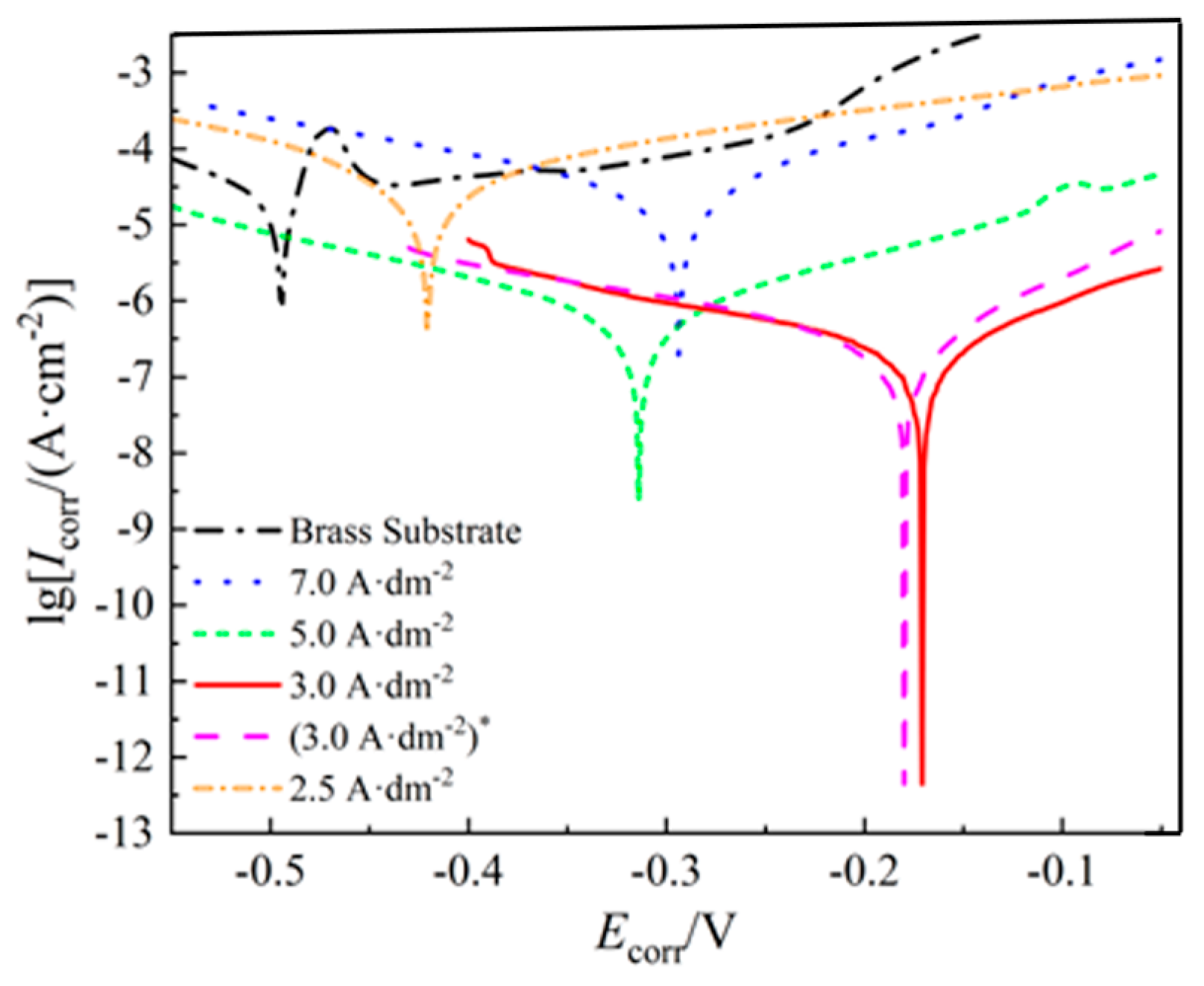
Figure 5 shows the polarization curves of the five groups of plated layers, in addition to the brass substrate. It is evident that the brass substrate exhibits the lowest corrosion potential, measuring approximately −0.5 V. The corrosion potential firstly increases and then decreases with rising current density, reaching a maximum value of approximately −0.18 V at a current density of 3.0 A·dm−2. The corrosion current density exhibited an upward trend, followed by a subsequent downward trend, concomitant with the increasing of the plating current density. For the samples prepared at current densities of 2.5 A·dm−2 and 7.0 A·dm−2, their corrosion current densities are 4.47 × 10⁻⁵ A·cm−2 and 2.77 × 10⁻⁵ A·cm−2, respectively, which are significantly higher than those of the samples prepared at 3.0 A·dm−2 and 5.0 A·dm−2 (approximately 10−7 A·cm−2). This indicates that a low current density is insufficient to form a dense coating, while an excessively high current density introduces holes and cracks, thereby accelerating corrosion. For the samples obtained at current densities of 3.0 A·dm−2 and 5.0 A·dm−2, their corrosion current densities are approximately 10−7 A·cm−2, which is about three orders of magnitude lower than those of the samples prepared at 2.5 A·dm−2 and 7.0 A·dm−2 (on the order of 10−5 A·cm−2). This indicates a significant improvement in their corrosion resistance. This is three orders of magnitude smaller than the values for the previous two samples, suggesting that the corrosion rate of the samples was greatly reduced, and the corrosion resistance was significantly improved. It is evident that the current density parameter of the plating exhibiting optimal corrosion resistance is situated within the range of approximately 3.0 A·dm−2 to 5.0 A·dm−2.
In order to ascertain the optimum parameters for the plating process, the corrosion rate of the alloy was calculated using the following equation [20].
v c = I c K m e ρ A
where vc is the corrosion rate, mm/a; Ic is the corrosion current density, A·cm−2; K is the corrosion rate constant, taken as K = 3272 mm/a; me is the equivalent mass, g; ρ is the density of the samples, g·cm−3; A is the effective area of the samples, cm2. In this paper, the effective area of the samples is 1 cm2. The specific data for the corrosion resistance test shown in Table 3 were finally obtained through the analysis.
Generally speaking, an increase in corrosion current, accompanied by a decline in corrosion potential, is associated with a deterioration in the corrosion resistance of the plating [21]. As demonstrated in Figure 5 and Table 3, it is evident that the 2.5 A·dm−2 plating exhibits the highest corrosion current, the most negative corrosion potential, and the poorest corrosion resistance. The lower applied current density results in an uneven thickness of the plating layer, thereby compromising the corrosion resistance. In comparison with the 7.0 A·dm−2 layer, the 5.0 A·dm−2 layer exhibits a more negative corrosion potential. However, when the results of the comparison of corrosion current and corrosion rate are taken into consideration, it can be concluded that the corrosion resistance of the 5.0 A·dm−2 layer is superior to that of the 7.0 A·dm−2 layer. The 3.0 A·dm−2 plating exhibited a reduced corrosion current, an augmented corrosion potential, and an enhanced corrosion resistance when compared to the other groups of plating, with the exception of the (3.0 A·dm−2)* plating. In summary, the (3.0 A·dm−2)* plating exhibited the lowest corrosion current of 2.59 × 10⁻⁷ A·cm−2 and the slowest corrosion rate of 0.023 mm/a, thereby demonstrating its optimal corrosion resistance.

3.3.2. EIS Curve Analysis

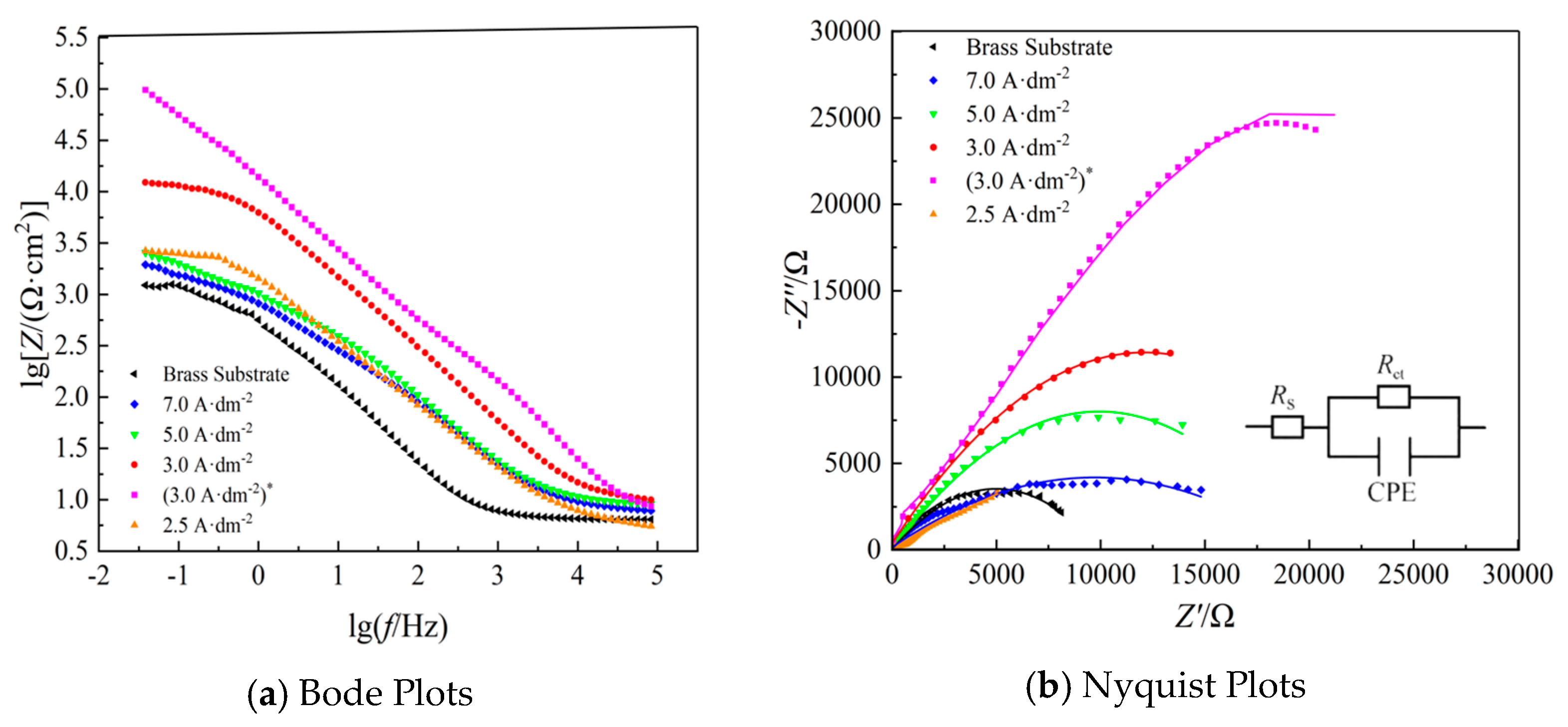
Figure 6 shows the Bode and Nyquist plots of the samples. An equivalent circuit diagram was established to investigate the corrosion of the Ni coating, as shown in the inset of Figure 6b. In this diagram, Rs represents the impedance of the solution between the sample and the electrode, Rct represents the charge transfer resistance, and CPE is the constant phase angle element [12,13,14,15,16,17,18,19,20,21,22,23].
As demonstrated in Figure 6a, the slope of (3.0 A·dm−2)* plating is observed to be the most significant in the low-frequency region, gradually decreasing to 0 as frequency increases. This finding suggests that the plating initially experiences a slight polarized corrosion, followed by a phase of gradual passivation. As the same time, the (3.0 A·dm−2)* coating exhibits the maximum tolerant arc radius, indicating that the charge transfer resistance Rct is the most substantial. This suggests that the (3.0 A·dm−2)* coating possesses the optimal corrosion resistance when compared with the other groups of coatings [24].
In order to quantify the effect of current density on the corrosion resistance of the plating, the polarization resistance Rp was calculated according to the Stern-Geary equation in Equation (2) [16].
R p = β a β c 2.3 I c o r r ( β a + β c )
where Rp is the polarization resistance; Icorr is the current density at the corrosion potential; βα and βc are the anodic and cathodic slopes of the Tafel curve, respectively, and the results of the calculations are shown in Table 4 . Also the equivalent circuit previously referenced was implemented utilizing Z-view software 2.0 version, and the precise values of each constituent parameter in the equivalent circuit were obtained and summarized in Table 4. The fitting curves are demonstrated in Figure 6b. In Table 4, CPE-T represents the capacitance of the double electric layer, and CPE-P represents the phase of the element. The closer the value is to 1, the CPE behaves as an ideal capacitance [25]. Conversely, the closer it is to 0.5, the element behaves as a Warburg impedance characteristic. It is widely accepted that an increase in polarization resistance is indicative of enhanced corrosion resistance in the sample [26]. It has been demonstrated that an increase in the capacitance of the double electric layer results in a more uniform current potential distribution on the electrode surface and a smoother electrode surface [27].
As illustrated in Table 4, the charge transfer resistance Rct and the polarization resistance Rp of the (3.0 A·dm−2)* coating are the most significant, with values of 5488 Ω·cm−2 and 6381.55 Ω·cm−2, respectively. These findings suggest that the coating exerts the strongest blocking effect on the electrons within the corrosion circuit. The phase CPE-P of the element is closest to 1, indicating that its electrical characteristics are closest to the ideal capacitance and that the blocking effect on the corrosive liquid is most obvious.

4. Conclusions

In this paper, nickel coatings were prepared on brass substrates using the direct current (DC) electrodeposition technique. The current density was optimized and the effect of different cathode and anode placements on the corrosion resistance and emissivity of the plating was compared as well. It was established that the emissivity of the samples exhibited an increase and subsequent decrease, in conjunction with an increase in current density. The optimal thermal emission and corrosion resistance of nickel coatings was achieved at a current density of 3.0 A·dm−2, with the cathode and anode positioned perpendicular to the horizontal plane. The surface of the coating was found to be uniformly smooth and free of pinholes, exhibiting uniform and dense micro-morphology. The polarization tests and electrochemical impedance results demonstrated that the coating exhibited the largest capacitance arc radius at a minimum corrosion current density of 2.59 × 10⁻⁷ A·cm2, the slowest corrosion rate of 0.023 mm/a, and a maximum polarization resistance of 6381.55 Ω·cm2. The obtained corrosion parameters are applicable to the range of deposition conditions set in this study, while the corrosion behavior under different deposition thicknesses/lower operating conditions needs to be further verified in subsequent work. The present work provides a significant experimental basis and reference point for the study of electrochemically deposited nickel coatings on brass substrates.

Author Contributions

Conceptualization, L.Z. and M.Z. (Min Zhang); Methodology, M.L. and H.Z.; Validation, X.Z., M.Z. (Mingyue Zhao) and H.Z.; Formal analysis, H.Z.; Investigation, L.Z., H.Z., M.Z. (Mingyue Zhao); Resources, M.L. ; Data curation, X.Z.; Writing—original draft preparation, L.Z., H.Z.; Writing—review and editing, M.Z. (Min Zhang); Supervision, M.Z. (Min Zhang); Project administration, L.Z.; Funding acquisition, L.Z. All authors have read and agreed to the published version of the manuscript.

Funding

This research was supported by the open project of Key Laboratory of Green Fabrication and Surface Technology of Advanced Metal Materials (Grant No. GFST2024KF01), the Liaoning Revitalization Talents Progrma, China (No. XLYC1807170) and Liaoning BaiQianQan Talents Program.

Institutional Review Board Statement

Not applicable.

Informed Consent Statement

Not applicable.

Data Availability Statement

The original contributions presented in the study are included in the article, further inquiries can be directed to the corresponding author.

Conflicts of Interest

The authors declare no conflicts of interest.

References

  1. Zhang, S.; Zhang, M.; Jiang, H.; Chen, L.; Han, D.; Hu, X.; Qiu, L. Tribological behavior and wear mechanism of TiO2/MoS2 nanocomposite coatings fabricated on TC6 alloys by micro-arc oxidation and duplex surface technologies. Surf. Coat. Technol. 2025, 510, 132227. [Google Scholar] [CrossRef]
  2. Ma, X.; Qi, N.; Zhang, M. First-principles investigation of Zn-doped β-Ga2O3: Electronic, optoelectronic, and thermodynamic properties. Phys. B: Condens. Matter 2025, 715, 417557. [Google Scholar] [CrossRef]
  3. Hu, W.; Zhang, M.; Ma, X.; Lv, M.; Zhou, X.; Kim, K.H. Structural, optical property and solar-blind photoelectric detection performance of high-quality Mg-doped β-Ga2O3 thin films prepared using RF magnetron sputtering. Surf. Coat. Technol. 2025, 506, 132144. [Google Scholar] [CrossRef]
  4. Chai, D.; Jia, Y.; Zhao, M.; Li, J.; Feng, W. Preparation of gradient nickel coating on copper by electrodeposition and study on its hydrogen evolution property. Electroplat. Finish. 2019, 38, 641–646. [Google Scholar] [CrossRef]
  5. Hu, X.; Zhang, M.; Pan, Y.; Huang, Y.; Cheng, S.; Ding, Y.; Pei, W. Effect of Bath Temperature on Microstructure of Ni-SiC Nanocomposite Coating by Electrochemical Deposition. China Surf. Eng. 2013, 26, 70–74. [Google Scholar]
  6. Gao, M.; Xie, H.; Fang, Y.; Wang, H.T.; Liu, J.B. Progress in surface treatment techniques of copper and copper alloys. Chin. J. Nonferr. Met. 2021, 31, 1121–1133. [Google Scholar]
  7. Kan, H.; Meng, Y.; Cui, S.; Kong, L.; Wang, X.; Long, H. Research Progress on Electrodeposited Nickel-Based Composite Coatings. Mater. Mech. Eng. 2021, 45, 1–7. [Google Scholar]
  8. Wang, H.; Zhai, X.; Sun, Y. Microstructure and corrosion resistance of in-suit coating on copper alloy using laser shock melt injection of fine-CeO2 particles. Mater. Res. Express 2020, 7, 116–302. [Google Scholar] [CrossRef]
  9. Li, Q.; Xu, G.; Chen, Y.; Xu, F.; Jiang, Y. Study of Thermal Endurance and Thermal Shock Resistance of High-emissivity Coating on Metal Substrate. Infrared Technol. 2011, 33, 284–288. [Google Scholar]
  10. Wang, Q.; Guo, X.; Wu, W.; Zhang, J.; Liu, L. Preparation and properties of metal oxide coatings with high emissivity on stainless steel. Trans. Mater. Heat Treat. 2012, 33, 137–141. [Google Scholar]
  11. Lee, J.; Bae, K.; Jung, K.; Jeong, J.H.; Ko, J.S. Creation of microstructured surfaces using Cu–Ni composite electrodeposition and their application to superhydrophobic surfaces. Appl. Surf. Sci. 2014, 289, 14–20. [Google Scholar] [CrossRef]
  12. Xiao, Q.; Chen, W.; Chen, Y.; Zou, J.; Cheng, B.; Zhang, X. Corrosion Resistance of Electrodeposited Ni-W-Ti3C2Tx Composite Coatings with Different Current Densities. Rear Met. 2022, 46, 1298–1305. [Google Scholar]
  13. Cheng, H.; Guo, H.; Wang, Q.; Wang, C.; Tang, Y. Electrodeposition Technology and Corrosion Resistance of Ni-Fe Alloy Coating. Plat. Finish. 2011, 6, 1–4. [Google Scholar]
  14. Li, T.; Liu, X.; Liu, W.; Qu, M. Nickel electroplating on pure copper tube heat exchanger. Electroplat. Finish. 2022, 41, 1049–1052. [Google Scholar]
  15. Somasundaram, S.; Pillai, A.M.; Rajendra, A.; Sharma, A.K. High emittance black nickel coating on copper substrate for space applications. J. Alloys Compd. 2015, 643, 263–269. [Google Scholar] [CrossRef]
  16. Stern, M.; Geary, A. Electrochemical polarization: I. A theoretical analysis of the shape of polarization curves. J. Electrochem. Soc. 1957, 104, 56–63. [Google Scholar] [CrossRef]
  17. Xing, Y.; Wang, Y.; Shi, X.; Meng, F.; Li, C.; Liu, S. Effect of Deposition Current on Electrocatalytic Hydrogen Evolution Performance of Electroplated Nickel. Plat. Finish. 2022, 10, 49–53. [Google Scholar]
  18. Li, P.; Ren, C.; Zhang, J.; Chen, T. Effect of current density on nickel electroplating of silicon carbide. Electroplat. Finish. 2022, 41, 770–773. [Google Scholar]
  19. Li, H.; Lu, S.; Qin, W.; Wu, X. Current Density on Microstructure and Thermal Control Performances of MgO-ZnO Ceramic Coatings. J. Inorg. Mater. 2017, 32, 1292–1298. [Google Scholar]
  20. Prasai, D.; Tuberquia, J.C.; Harl, R.R.; Jennings, G.K.; Bolotin, K.I. Graphene: Corrosion-inhibiting coating. ACS Nano 2012, 6, 1102–1108. [Google Scholar] [CrossRef]
  21. Yang, C.; Yao, Z.; Zhang, F.; Oleksandr, M. Repairing the specified track on the copper coating surface via area-selective electrodeposition. J. Mater. Res. 2021, 36, 812–821. [Google Scholar] [CrossRef]
  22. Li, C.; Du, S.; Zeng, Z.; Liu, E.; Wang, F.; Ma, F. Effect of Current Density on Microstructure, Wear and Corrosion Resistance of Electrodeposited Ni-Co-B Coating. J. Chin. Soc. Corros. Prot. 2020, 40, 439–447. [Google Scholar] [CrossRef]
  23. Zhang, M.; Ma, X.; Zhang, S.; Hou, L.; Kim, K.H. One-step fabrication of wear resistant and friction-reducing Al2O3/MoS2 nanocomposite coatings on 2A50 aluminum alloy by plasma electrolytic oxidation with MoS2 nanoparticle additive. Surf. Coat. Technol. 2025, 497, 131796. [Google Scholar] [CrossRef]
  24. Hu, J.; Chen, J.; Chen, L.; Li, S.; Huang, D.; Chen, Z.; Chen, H.; Xie, W. Effect of Electroplating Current Density on Corrosion Resistance of Al2O3-Ni Composite Coating. Guangdong Chem. Ind. 2023, 50, 24–26. [Google Scholar]
  25. Li, Y.; Lin, L.; Dai, W.; Chen, Z.; Liu, F.; Chen, L. Preparation of copper–nickel–molybdate alloy electrode by electrodeposition at gradient current densities and study on its properties. Electroplat. Finish. 2020, 39, 521–526. [Google Scholar]
  26. Liang, H.; Hou, J.; Jiang, L.; Qi, Z.; Zhang, M.; Cao, Z. The Effect of Heat Treatment on the Microstructure and Mechanical Properties of Al0.6CoFeNi2V0.5 High Entropy Alloy. Coatings 2024, 14, 658. [Google Scholar] [CrossRef]
  27. Ye, C.; You, D.; Qiu, C.; Li, Q. The Preparation and Corrosion Resistance of Electroless Ni-Cu-P Coating on Nd-Fe-B Permanent Magnet. Guangdong Chem. Ind. 2019, 46, 44–45. [Google Scholar]
Figure 1. Two different configurations of the anode and cathode.
Coatings 15 01276 g001
Figure 2. Photographs and optical micrographs of Ni coatings at different current densities.
Coatings 15 01276 g002
Figure 3. SEM images of the nickel coatings of (3.0 A·dm−2)* in vertical direction, (a) ×1000, (b) ×4000.
Coatings 15 01276 g003
Figure 4. The emissivity of the coatings obtained at different current densities. Note: The abscissa represents the current density (A·dm−2), including four groups of samples with horizontally placed cathodes (at current densities of 2.5, 3.0, 5.0, and 7.0 A·dm−2) and one group of samples with vertically placed cathodes (marked as (3.0 A·dm−2)*). Among these samples, the one with the vertical configuration exhibits the highest emissivity (0.92) at the same current density of 3.0 A·dm−2.
Coatings 15 01276 g004
Figure 5. Polarization curves of the samples obtained at different current densities.
Coatings 15 01276 g005
Figure 6. Electrochemical impedance spectra of the samples obtained at different current densities.
Coatings 15 01276 g006
Table 1. Parameters for the electroplating experiments to optimize current density.
SamplesTime
(min)
Temperature
(°C)
Current Density
(A·dm−2)
Starting Voltage
(V)
End Voltage
(V)
Coating Thickness
(μm)
130RT2.51.81.77.1 ± 1.5
23.02.12.010.6 ± 0.8
35.02.42.216.4 ± 1.1
47.03.22.918.2 ± 1.2
Table 2. Parameters for the two configurations of the electrodes.
Sample No.Time
(min)
Temperature
(°C)
Current Density
(A·dm−2)
Placement MethodStarting Voltage
(V)
End Voltage
(V)
Coating Thickness
(μm)
230RT3.0(a) Horizontal2.12.010.6 ± 0.8
5(b) Vertical2.62.513.8 ± 0.6
Note: Samples 2 and 5 were plated at the same current density (3.0 A·dm−2) but with different electrode configurations. To distinguish them, Sample 5 is denoted as (3.0 A·dm−2)* in the table.
Table 3. Tafel curve fitting data and calculation results for the bare and coated substrates.
SamplesIcorr/(A·cm−2)Ecorr/Vme/gVc/(mm/a)
Brass substrate3.46 × 10−4.9−0.49713.610.564
7.0 A·dm−22.77 × 10⁻⁵−0.29410.270.252
5.0 A·dm−27.63 × 10⁻⁷−0.31410.700.072
2.5 A·dm−24.47 × 10⁻⁵−0.42111.370.423
3.0 A·dm−23.10 × 10⁻⁷−0.17110.100.028
(3.0 A·dm−2)*2.59 × 10−7−0.18010.320.023
Table 4. Fitted data of electrochemical impedance spectra for each group of coatings.
SamplesRp/(Ω·cm−2)Rs/(Ω·cm−2)Rct/(Ω·cm−2)Q (CPE-T) (F·sn−1·cm−2)n
Brass substrate1638.065.01210632.49 × 10−40.37
7.0 A·dm−23157.146.85420581.72 × 10−40.64
5.0 A·dm−23875.865.05340331.70 × 10−40.67
2.5 A·dm−22596.356.00311481.38 × 10−40.74
3.0 A·dm−24233.028.82241337.67 × 10−40.79
(3.0 A·dm−2)*6381.555.99054881.00 × 10−30.95
Note: Q (CPE-T)—magnitude of the constant phase element (CPE), given here in units of F·sn−1·cm−2. n—CPE exponent (dimensionless), 0 < n ≤ 1. n = 1 corresponds to an ideal capacitor; n < 1 indicates dispersion/deviation from ideal capacitive behavior (e.g., surface roughness, porosity or inhomogeneity). CPE impedance is defined as ZCPE = 1 Q ( j w ) n .
Disclaimer/Publisher’s Note: The statements, opinions and data contained in all publications are solely those of the individual author(s) and contributor(s) and not of MDPI and/or the editor(s). MDPI and/or the editor(s) disclaim responsibility for any injury to people or property resulting from any ideas, methods, instructions or products referred to in the content.