
The Damage Evolution of a Cr2O3-TiO2 Coating Subjected to Cyclic Impact and Corrosive Environments and the Influence of a Nickel Intermediate Layer

Abstract
1. Introduction
2. Experiments
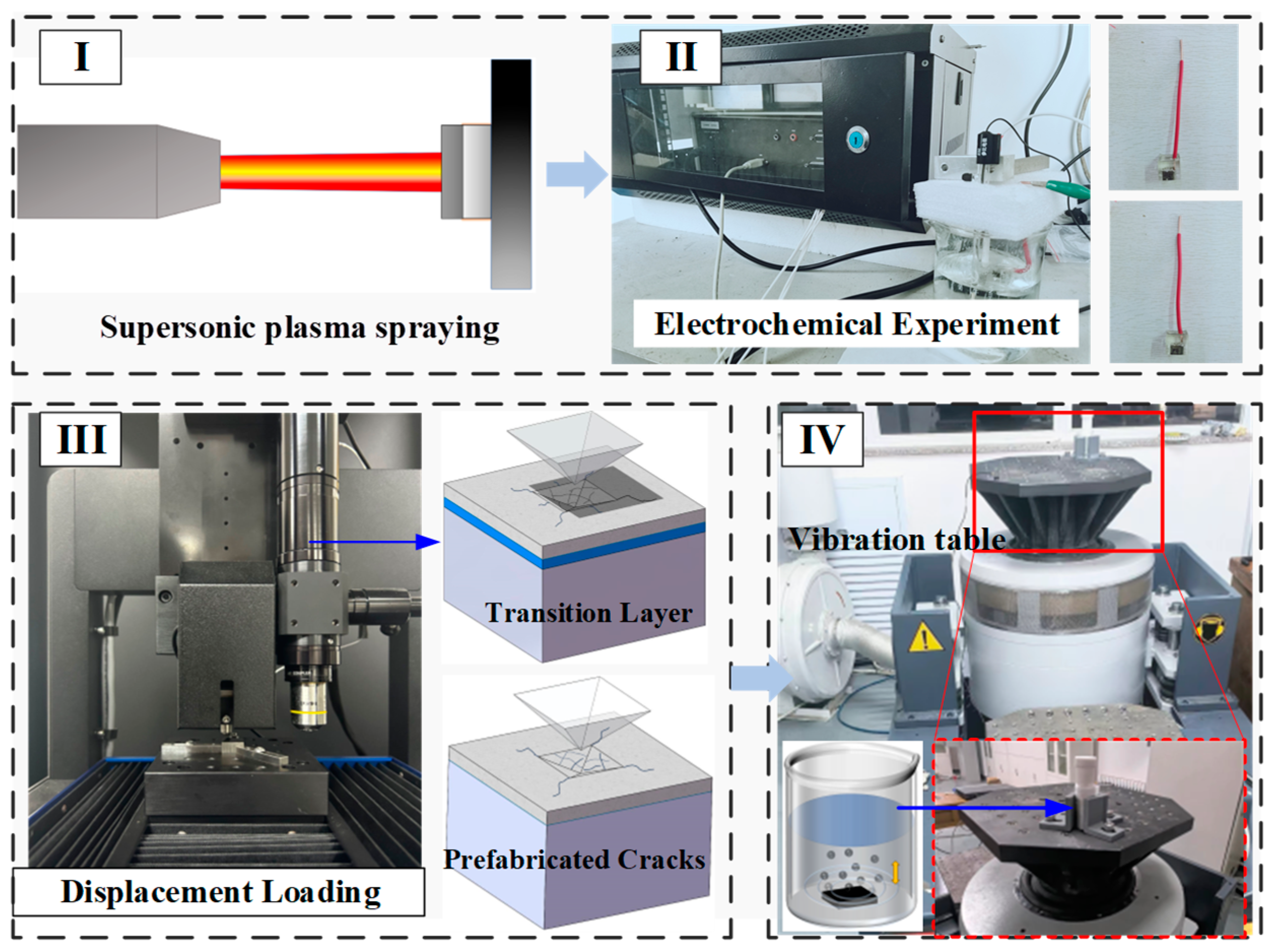
2.1. The Preparation of CT Coatings
2.2. Corrosion and Electrochemical Experiments
2.3. Crack Prefabrication
2.4. Cyclic Impact Experiment in Corrosive Media
2.5. Characterization Techniques
3. Results and Discussion
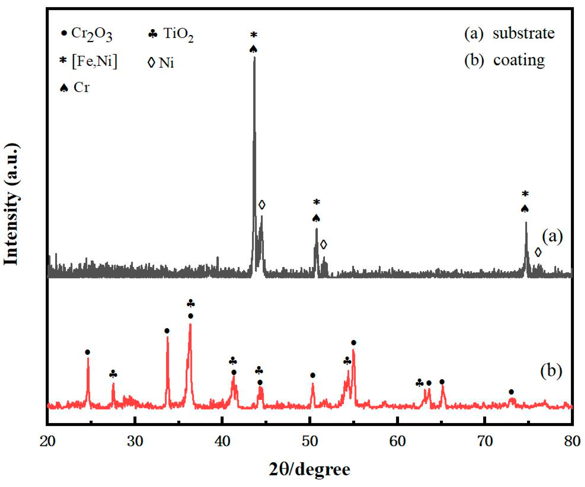
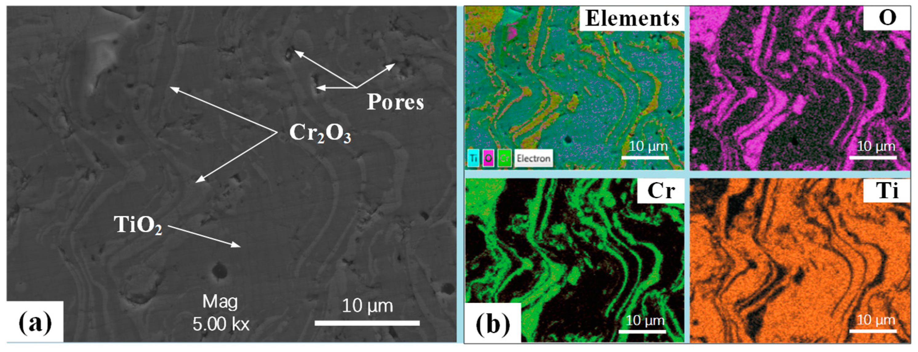
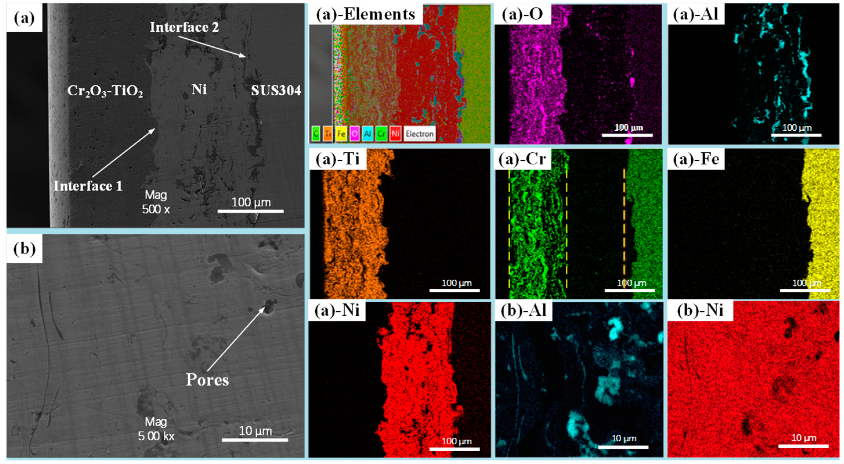
3.1. Microscopic Characteristics of CT Coating–Substrate System
3.2. Interfacial Crack Formation
3.3. Electrochemical Characteristics
3.4. Damage Evolution of the Coating–Substrate System
4. Conclusions
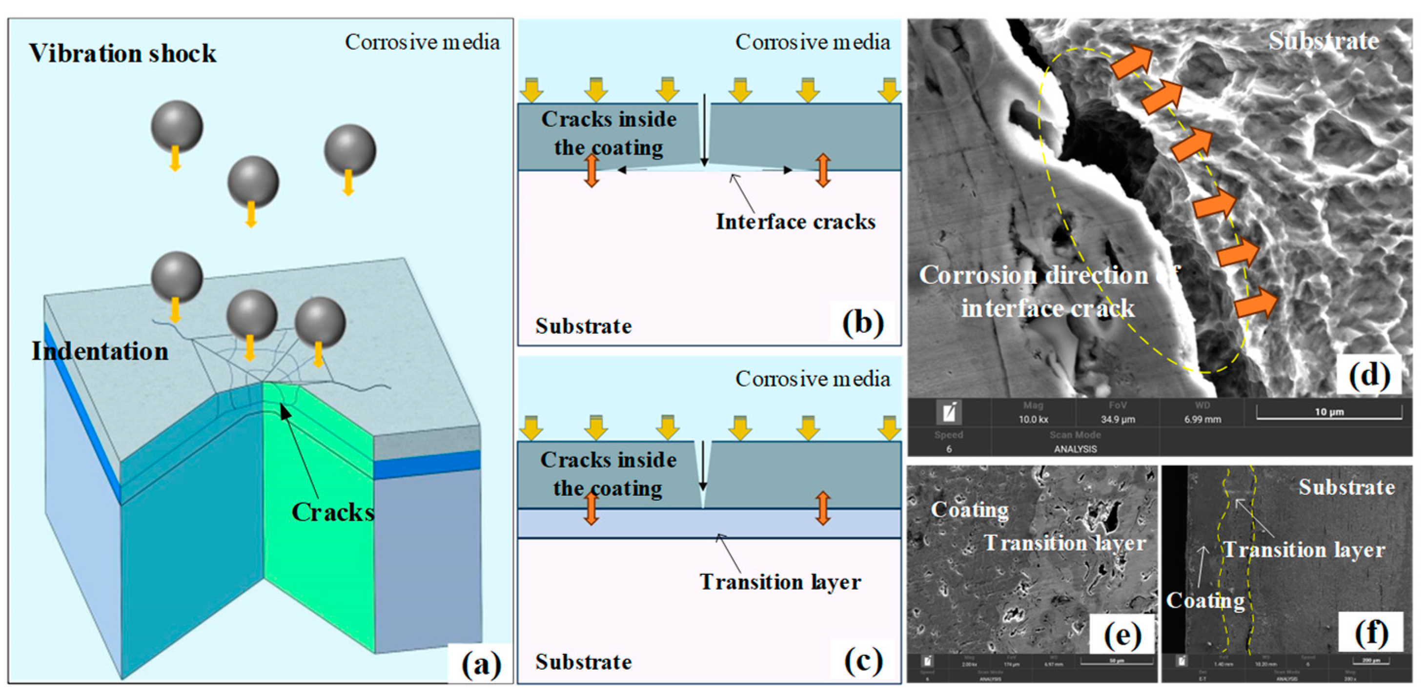
- (a)
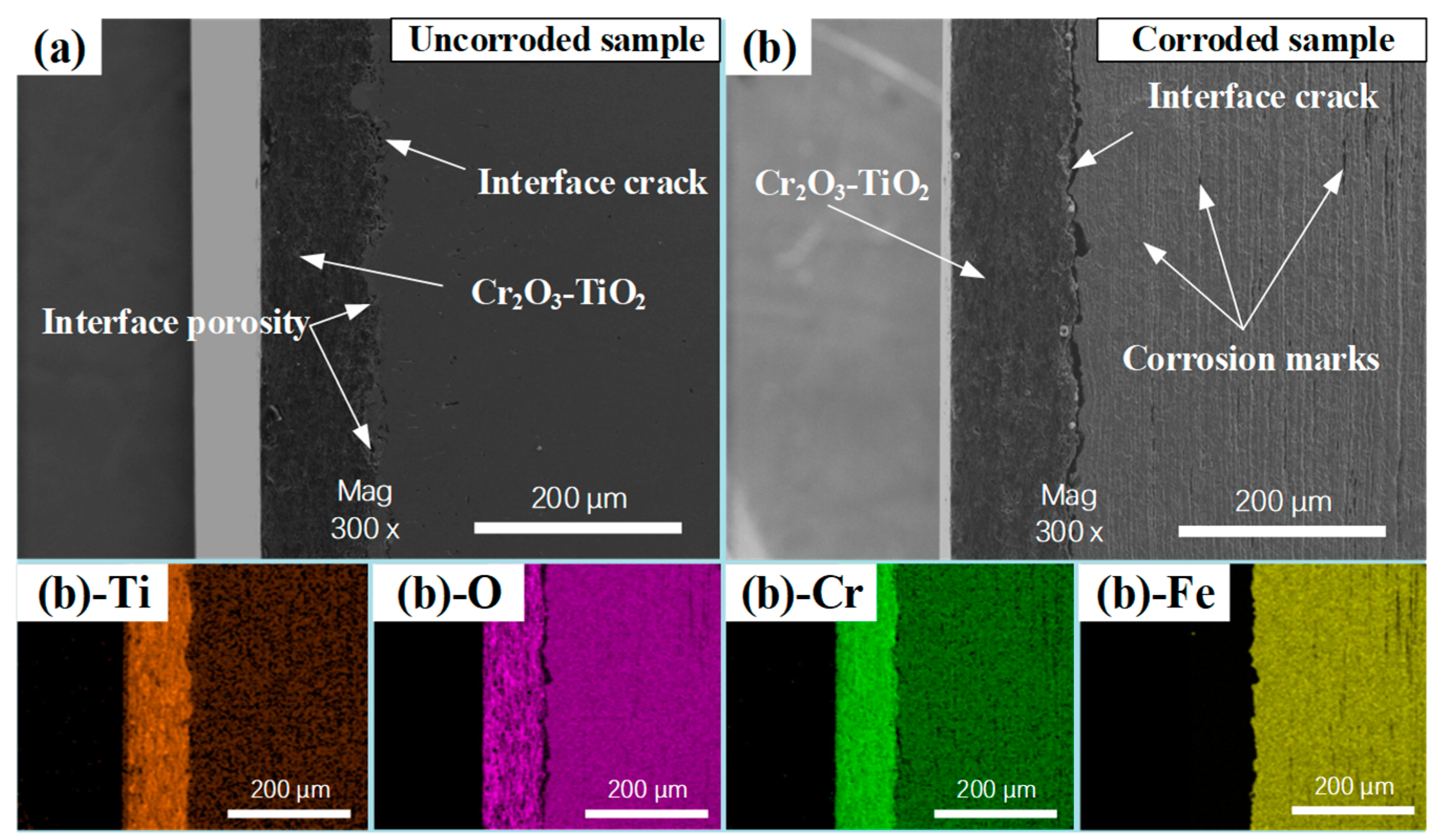
- The formation of interfacial cracks primarily depends on the corrosion resistance of the materials on either side of the interface. Therefore, the addition of a nickel layer effectively inhibits the formation of cracks between the ceramic coating and the nickel layer. However, it cannot prevent the formation of cracks between the nickel layer and the substrate, which is due to the substrate’s poor corrosion resistance.
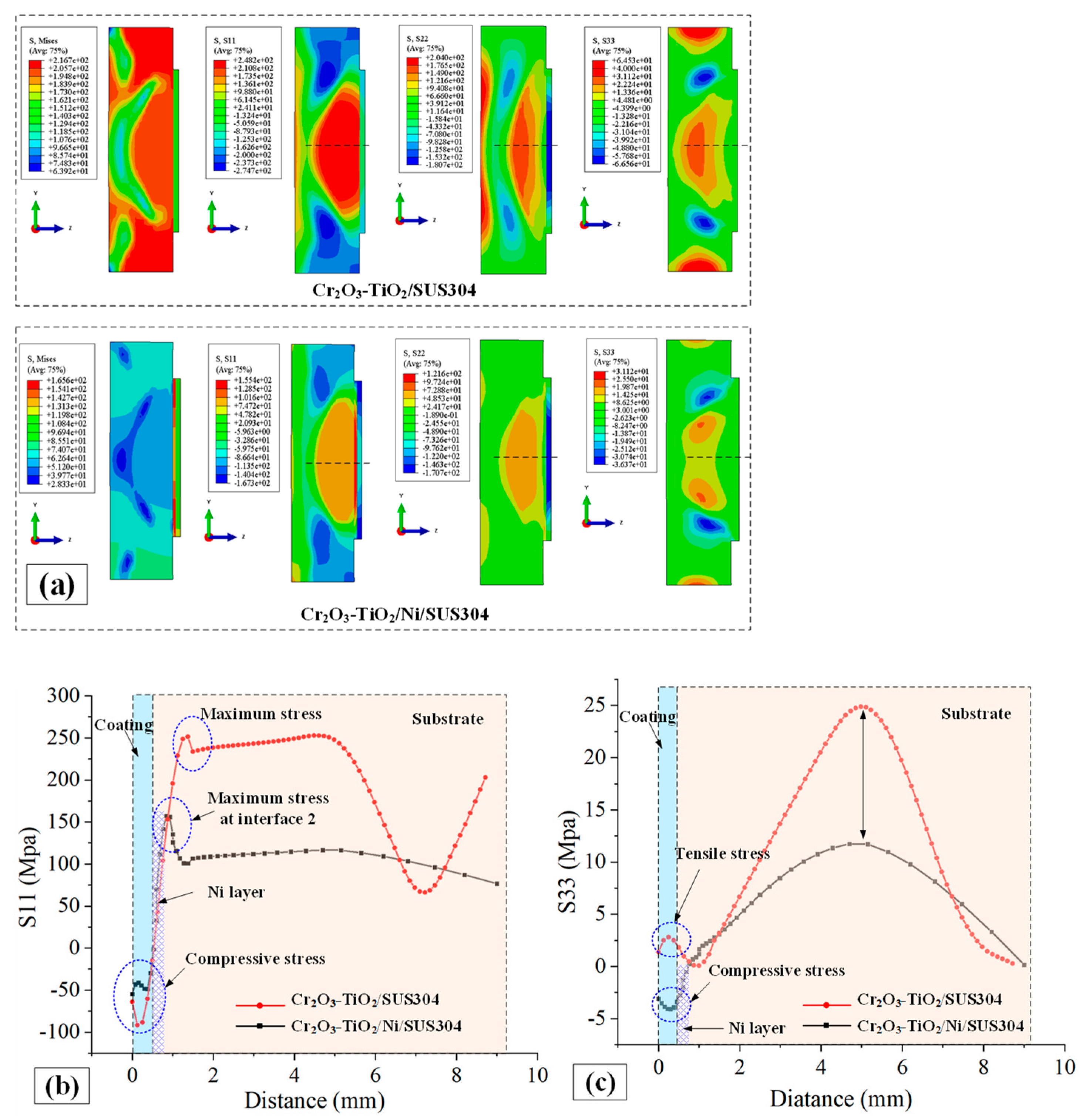
- (b)
- The nickel layer reduces the stress on the coating and substrate, but stress concentration occurs near the interface between the nickel layer and substrate. The stress in the Z-axis direction changes from tensile stress to compressive stress.
- (c)
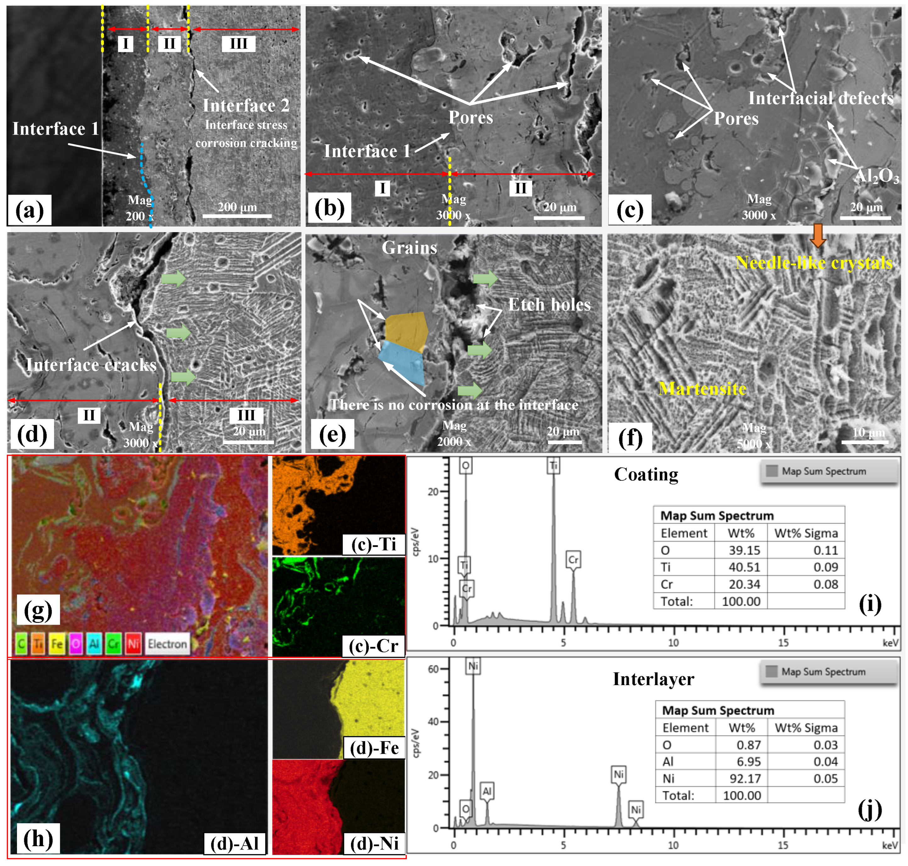
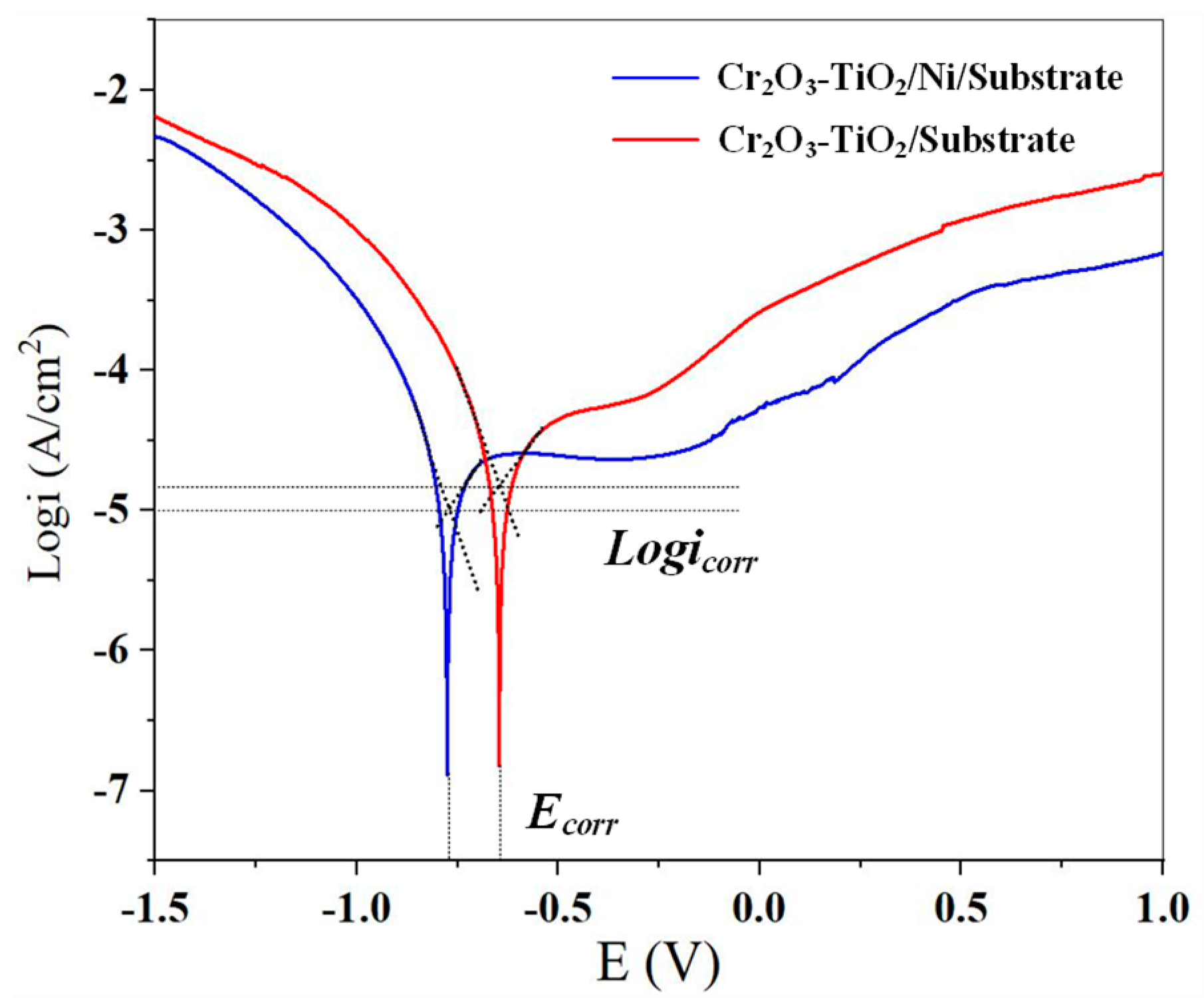
- The presence of the nickel layer enhances the corrosion resistance of the coating–substrate system and strengthens the passicvation phenomenon. The corrosion potential of the CT/Ni/Substrate sample increased from −0.657 V to −0.766 V, and the corrosion current density decreased from 9.197 × 10⁻⁶ A/cm2 to 8.088 × 10⁻⁶ A/cm2.
- (d)
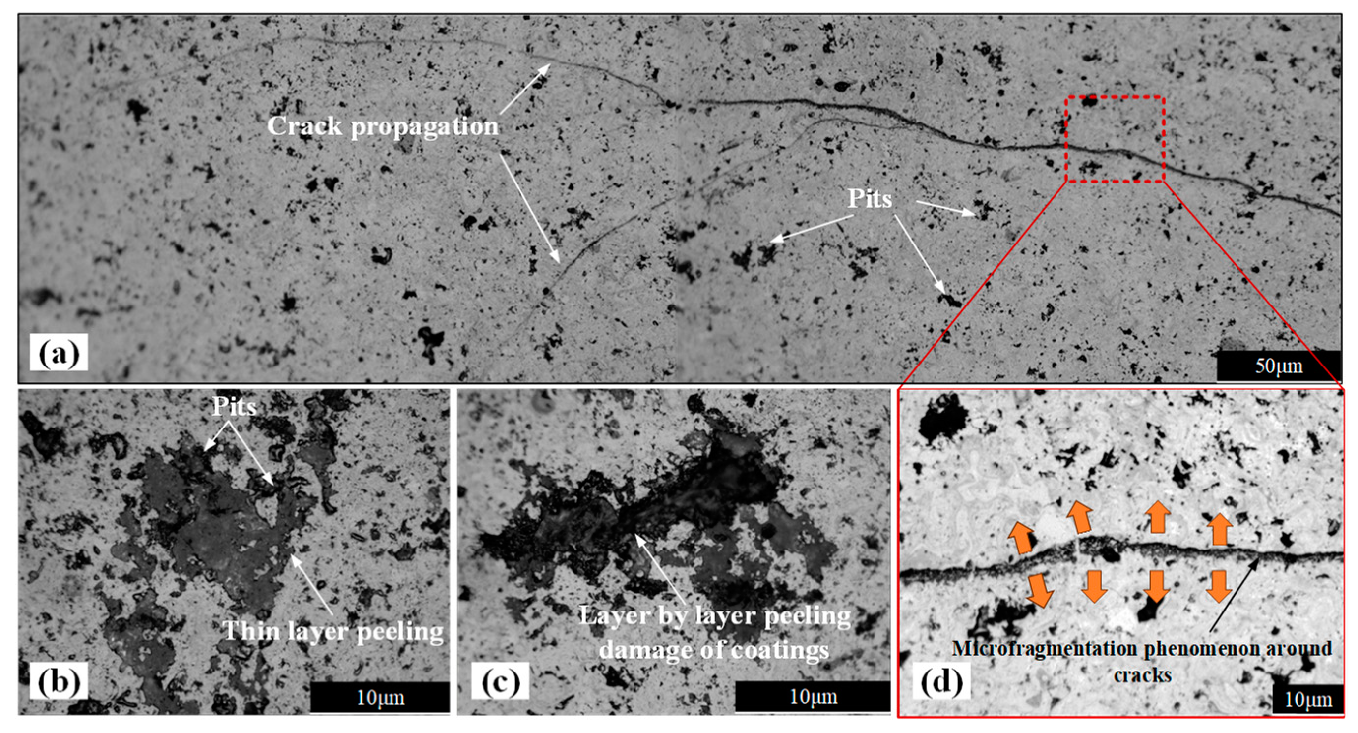
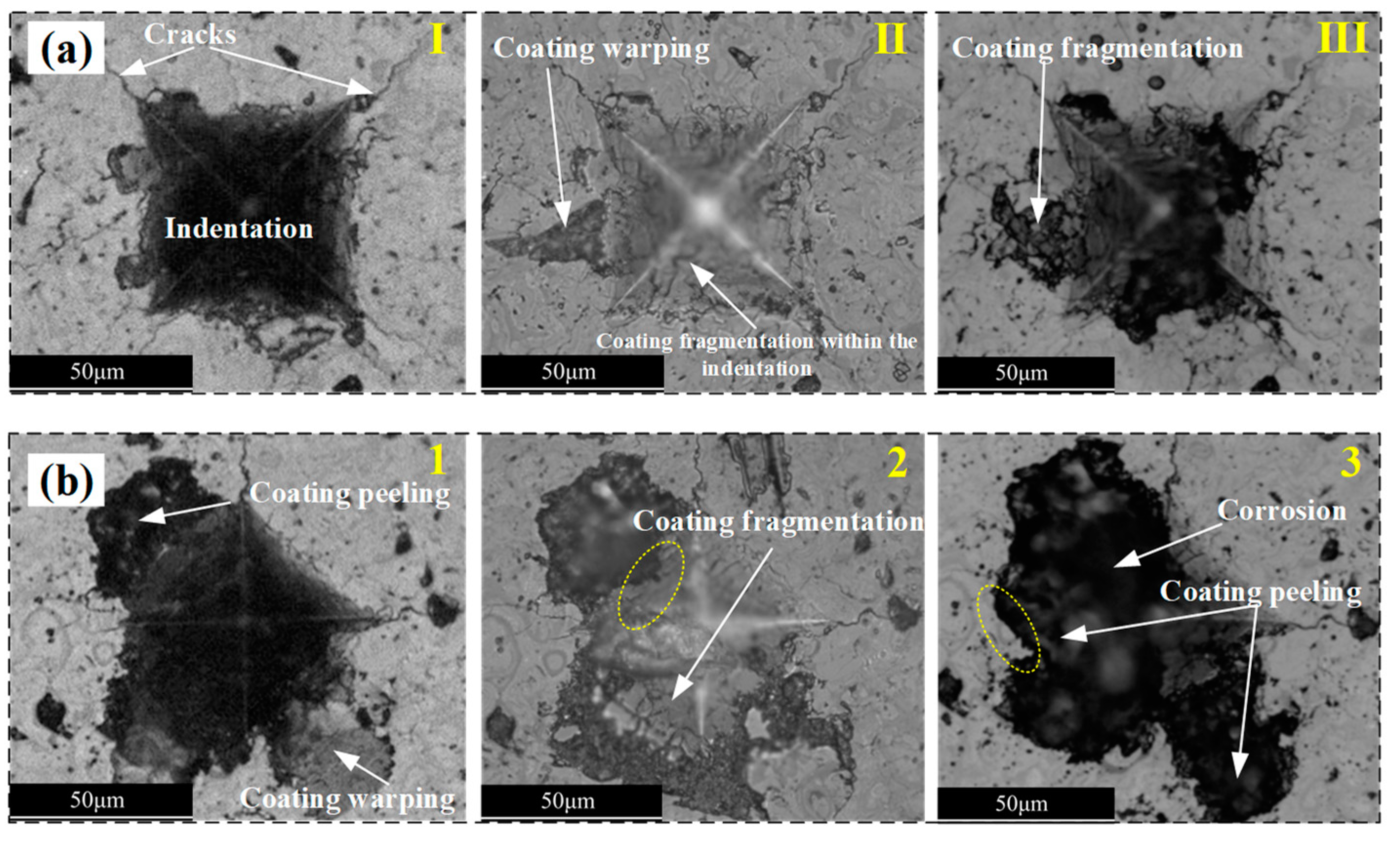
- The combined effects of corrosion and impact result in two types of damage on the surface of ceramic coatings: through-thickness cracks and corrosion pits. Through-thickness cracks are the primary cause of interfacial cracks, while corrosion pits arise from the progressive delamination of the ceramic coating layers.
Author Contributions
Funding
Data Availability Statement
Conflicts of Interest
References
- Han, C.; Wang, Z.; Ma, L.; Huang, G.; Ma, Y. Cold spray for ceramic metallisation: A review. Adv. Appl. Ceram. 2021, 120, 358–380. [Google Scholar] [CrossRef]
- Missner, M.; Stryhalski, J.; Tomiyama, M.; Soares, P.; Recco, A.; Fontana, L. Rutile TiO2 thin films growth on glass substrates with generation of high entropy interface. J. Mater. Res. Technol. 2023, 24, 963–970. [Google Scholar] [CrossRef]
- Talavari, F.; Shakeri, A.; Mighani, H. Synthesis of Cr2O3/TiO2 nanocomposite and its application as the blocking layer in solar cells. J. Environ. Anal. Chem. 2018, 5, 2380–2391. [Google Scholar] [CrossRef]
- Dey, A.; Banerjee, K.; Mukhopadhyay, A.K. Microplasma sprayed hydroxyapatite coating: Emerging technology for biomedical application. Mater. Technol. 2014, 29, 15–20. [Google Scholar] [CrossRef]
- Zhang, H.; Wang, Y.; Chen, X.; Zhang, Z.; Zeng, X.; Cheng, X. Corrosion behaviors of Al2O3–20TiO2 and Cr2O3–3TiO2–5SiO2 coatings in both artificial seawater and high-pressure hydrogen sulfide seawater. Ceram. Int. 2024, 50, 34346–34356. [Google Scholar] [CrossRef]
- Lakshmi, K.P.J.; Irappa, S.; Raghavendra, C.R.; Basavarajappa, S. High temperature erosive behaviour of plasma sprayed NiCrAlY/B4C/Cenospherecoating on MDN 321 turbine steel. Int. J. Surf. Eng. Coat. 2023, 101, 49–56. [Google Scholar]
- Zavareh, M.A.; Sarhan, A.A.D.M.; Karimzadeh, R.; Singh, R.S.A. Analysis of corrosion protection behavior of Al2O3-TiO2 oxide ceramic coating on carbon steel pipes for petroleum industry. Ceram. Int. 2018, 44, 5967–5975. [Google Scholar] [CrossRef]
- Vernhes, L.; Bekins, C.; Lourdel, N.; Poirier, D.; Lima, R.S.; Li, D.; Klemberg-Sapieha, J.E. Nanostructured and conventional Cr2O3, TiO2, and TiO2-Cr2O3 thermal-sprayed coatings for metal-seated ball valve applications in hydrometallurgy. J. Therm. Spray Technol. 2016, 25, 1068–1078. [Google Scholar] [CrossRef]
- Rasooli, A.; Safavi, M.S.; Hokmabad, M.K. Cr2O3 nanoparticles: A promising candidate to improve the mechanical properties and corrosion resistance of Ni-Co alloy coatings. Ceram. Int. 2018, 44, 6466–6473. [Google Scholar] [CrossRef]
- He, X.; Song, P.; Huang, T.; Wan, F.; Kong, D.; Zhai, R.; Hua, C.; Dai, J. Fracture process simulation and crack resistance behavior analysis of transition-layer ceramic coating based on real image reconstruction model. Surf. Interfaces 2024, 46, 104003. [Google Scholar] [CrossRef]
- Babu, P.S.; Sen, D.; Jyothirmayi, A.; Krishna, L.R.; Rao, D.S. Influence of microstructure on the wear and corrosion behavior of detonation sprayed Cr2O3-Al2O3 and plasma sprayed Cr2O3 coatings. Ceram. Int. 2018, 44, 2351–2357. [Google Scholar] [CrossRef]
- Wang, S.; Liu, X.; Zhang, J.; Xu, P.; Wei, M.; Liu, G.; Zhan, X.; Coyle, T.W.; Mostaghimi, J. Tailoring the wetting behaviors and surface structures of yttrium oxide coatings deposited via different plasma spray processes. J. Mater. Res. Technol. 2024, 29, 1924–1936. [Google Scholar] [CrossRef]
- Ahmadian, S.; Jordan, E.H. Explanation of the effect of rapid cycling on oxidation, rumpling, microcracking and lifetime of air plasma sprayed thermal barrier coatings. Surf. Coat. Technol. 2014, 244, 109–116. [Google Scholar] [CrossRef]
- Kovářík, O.; Haušild, P.; Medřický, J.; Tomek, L.; Siegl, J.; Mušálek, R.; Curry, N.; Björklund, S. Fatigue Crack Growth in Bodies with Thermally Sprayed Coating. J. Therm. Spray Technol. 2016, 25, 311–320. [Google Scholar] [CrossRef]
- Mušálek, R.; Kovářík, O.; Matějíček, J. In-situ observation of crack propagation in thermally sprayed coatings. Surf. Coat. Technol. 2010, 205, 1807–1811. [Google Scholar] [CrossRef]
- Huang, B.; Wang, J.; Tang, Z.-H.; Li, W.-D.; Zhu, W.-J.; Gu, R.-B. Fluoride-mediated corrosion mechanism of atmospheric-plasma-sprayed yttrium–aluminium garnet ceramic coatings. J. Eur. Ceram. Soc. 2022, 42, 6146–6158. [Google Scholar] [CrossRef]
- Zamani, P.; Valefi, Z.; Jafarzadeh, K. Comprehensive study on corrosion protection properties of Al2O3, Cr2O3 and Al2O3–Cr2O3 ceramic coatings deposited by plasma spraying on carbon steel. Ceram. Int. 2022, 48, 1574–1588. [Google Scholar] [CrossRef]
- Chen, W.; Hu, T.; Wang, C.; Xiao, H.; Meng, X. The effect of microstructure on corrosion behavior of a novel AlCrTiSiN ceramic coating. Ceram. Int. 2020, 46, 12584–12592. [Google Scholar] [CrossRef]
- Zhang, Z.; Zhong, X.; Li, L.; Hu, J.; Peng, Z. Unmasking the delamination mechanisms of a defective coating under the co-existence of alternating stress and corrosion. Prog. Org. Coat. 2023, 180, 107560. [Google Scholar] [CrossRef]
- Ozkan, D. Structural characteristics and wear, oxidation, hot corrosion behaviors of HVOF sprayed Cr3C2-NiCr hardmetal coatings. Surf. Coat. Technol. 2023, 457, 129319. [Google Scholar] [CrossRef]
- Wang, Z.; Zhang, J.; Liu, X.; Liu, J.; Liu, G. Failure mechanism of plasma sprayed Tb-YSZ coating under NaCl high-low temperature cyclic corrosion. Surf. Coat. Technol. 2023, 456, 129244. [Google Scholar] [CrossRef]
- Hanifi, D.; Hakimi, N.; Ali, R.; Huang, T.; Huma, T.; Bakhshyar, D.; Afzali, N.R.; Shafi, M.; Babeker, H.; Lu, J.; et al. The fracture toughness and tribological performance of NiAl/Al2O3-40 Wt.% TiO2 coating generated by air plasma spraying. Ceram. Int. 2024, 50, 1533–1546. [Google Scholar] [CrossRef]
- Thirumalaikumarasamy, D.; Shanmugam, K.; Balasubramanian, V. Effect of atmospheric plasma spraying parameters on porosity level of alumina coatings. Surf. Eng. 2012, 28, 759–766. [Google Scholar] [CrossRef]
- Ctibor, P.; Lechnerová, R.; Beneš, V. Quantitative analysis of pores of two types in a plasma-sprayed coating. Mater. Charact. 2006, 56, 297–304. [Google Scholar] [CrossRef]
- Shukla, R.K.; Kumar, A.; Kumar, R.; Singh, D.; Kumar, A. Numerical study of pore formation in thermal spray coating process by investigating dynamics of air entrapment. Surf. Coat. Technol. 2019, 378, 124972. [Google Scholar] [CrossRef]
- Ferguen, N.; Leclerc, W.; Lamini, E.-S. Numerical investigation of thermal stresses induced interface delamination in plasma-sprayed thermal barrier coatings. Surf. Coat. Technol. 2023, 461, 129449. [Google Scholar] [CrossRef]
- Terán, G.; Capula-Colindres, S.; Velázquez, J.; Zuñiga-Hinojosa, M.; Contreras, A. Modeling 3D finite element analysis of a semi-elliptical crack on stress corrosion cracking of API X52 pipeline. Forces Mech. 2024, 16, 100279. [Google Scholar] [CrossRef]
- Han, C.; Yu, M.; Jia, X.; Zhao, Z.; Zhang, C.; Xiao, J.; Li, S.; Liu, J. Effect of inhomogeneous microstructures on stress corrosion cracking sensitivity of 2050-T84 Al-Li alloy thick plate. Corros. Sci. 2024, 235, 112213. [Google Scholar] [CrossRef]
- Wei, Z.-Y.; Cai, H.-N. Stress states and crack behavior in plasma sprayed TBCs based on a novel lamellar structure model with real interface morphology. Ceram. Int. 2019, 45, 16948–16962. [Google Scholar] [CrossRef]
- Loto, C.A. Stress corrosion cracking: Characteristics, mechanisms and experimental study. Int. J. Adv. Manuf. Technol. 2017, 93, 3567–3582. [Google Scholar] [CrossRef]
- Zhang, W.; Sun, J.; Ding, D.; Hou, D. Nanoscale insights on the stress corrosion mechanism of calcium-silicate-hydrate. J. Build. Eng. 2023, 80, 107991. [Google Scholar] [CrossRef]
- Tokaji, K.; Ogawa, T.; Hwang, J.U.; Kobayashi, Y.; Harada, Y. Corrosion Fatigue Behavior of a Steel with Sprayed Coatings. J. Therm. Spray Technol. 1996, 5, 269–276. [Google Scholar] [CrossRef]
- Morelli, S.; Bursich, S.; Testa, V.; Bolelli, G.; Miccichè, A.; Lusvarghi, L. CMAS corrosion and thermal cycling fatigue resistance of alternative thermal barrier coating materials and architectures: A comparative evaluation. Surf. Coat. Technol. 2022, 439, 128433. [Google Scholar] [CrossRef]
- Cai, H.; Shan, X.; Lu, J.; Luo, L.; Cai, Z.; Wang, W.; Zhang, X.; Zhao, X. The crack behavior and delamination mechanisms of air plasma sprayed thermal barrier coatings under ultrasonic plasma jet at 1600 °C. J. Eur. Ceram. Soc. 2023, 43, 4136–4145. [Google Scholar] [CrossRef]

| Process Parameters | Ni Layer | Ceramic Layer |
|---|---|---|
| Current/A | 300 | 500 |
| Voltage/V | 62 | 80 |
| Plasma gas flow (Ar)/L·min−1 | 60 | 60 |
| Plasma gas flow (H2)/L·min−1 | 10 | 15 |
| Spray distance (mm) | 100 | 100 |
| Powder feed rate (g/min) | 30 | 30 |
Disclaimer/Publisher’s Note: The statements, opinions and data contained in all publications are solely those of the individual author(s) and contributor(s) and not of MDPI and/or the editor(s). MDPI and/or the editor(s) disclaim responsibility for any injury to people or property resulting from any ideas, methods, instructions or products referred to in the content. |
© 2025 by the authors. Licensee MDPI, Basel, Switzerland. This article is an open access article distributed under the terms and conditions of the Creative Commons Attribution (CC BY) license (https://creativecommons.org/licenses/by/4.0/).
Share and Cite
Yang, H.; Zhao, Y.; Qin, X.; Jin, Y.; Zhao, X.; Tian, K.; Wang, X.; Zhang, Z. The Damage Evolution of a Cr2O3-TiO2 Coating Subjected to Cyclic Impact and Corrosive Environments and the Influence of a Nickel Intermediate Layer. Coatings 2025, 15, 98. https://doi.org/10.3390/coatings15010098
Yang H, Zhao Y, Qin X, Jin Y, Zhao X, Tian K, Wang X, Zhang Z. The Damage Evolution of a Cr2O3-TiO2 Coating Subjected to Cyclic Impact and Corrosive Environments and the Influence of a Nickel Intermediate Layer. Coatings. 2025; 15(1):98. https://doi.org/10.3390/coatings15010098
Chicago/Turabian StyleYang, Huaxing, Yang Zhao, Xudong Qin, Yixin Jin, Xinyang Zhao, Kailin Tian, Xiaoming Wang, and Zhao Zhang. 2025. "The Damage Evolution of a Cr2O3-TiO2 Coating Subjected to Cyclic Impact and Corrosive Environments and the Influence of a Nickel Intermediate Layer" Coatings 15, no. 1: 98. https://doi.org/10.3390/coatings15010098
APA StyleYang, H., Zhao, Y., Qin, X., Jin, Y., Zhao, X., Tian, K., Wang, X., & Zhang, Z. (2025). The Damage Evolution of a Cr2O3-TiO2 Coating Subjected to Cyclic Impact and Corrosive Environments and the Influence of a Nickel Intermediate Layer. Coatings, 15(1), 98. https://doi.org/10.3390/coatings15010098