Article

Tribological and Mechanical Behavior of Automotive Crankshaft Steel Superficially Modified Using the Boriding Hardening Process

by
Enrique Hernández-Sánchez
1,*,
Diego Hernández-Domínguez
1,
Raúl Tadeo-Rosas
2,*,
Yesenia Sánchez-Fuentes
1,
Luz Alejandra Linares-Duarte
1,
Carlos Orozco-Álvarez
1,
José Guadalupe Miranda-Hernández
3 and
Rafael Carrera-Espinoza
4
1
Departamento de Bioingeniería, Instituto Politécnico Nacional, Unidad Profesional Interdisciplinaria de Biotecnología, Avenida Acueducto s/n Barrio la Laguna Ticomán, Mexico City 07340, Mexico
2
Facultad de Ingeniería Mecánica y Eléctrica, Universidad Autónoma de Coahuila, Unidad Torreón, Carretera Torreón-Matamoros, km 7.5, Ciudad Universitaria, Ejido el Águila, Torreón 27276, Mexico
3
Centro Universitario UAEM Valle de México, Laboratorio de Investigación y Desarrollo de Materiales Industriales, Universidad Autónoma del Estado de México, Atizapán de Zaragoza 54500, Mexico
4
Departamento de Ingeniería Industrial y Mecánica, Universidad de las Américas Puebla, Ex Hacienda Santa Catarina Mártir, San Andrés Cholula 72810, Mexico
*
Authors to whom correspondence should be addressed.
Coatings 2024, 14(6), 716; https://doi.org/10.3390/coatings14060716
Submission received: 10 May 2024 / Revised: 27 May 2024 / Accepted: 4 June 2024 / Published: 5 June 2024
(This article belongs to the Special Issue Surface Treatment on Metals and Their Alloys)

Abstract

:
One of the primary challenges in the automotive industry is the wear of engine components, such as the crankshaft and camshaft, which is the most pronounced during the engine’s startup phase, when the amount of lubricant fluid is at its lowest. This study aims to enhance the surface wear resistance of automotive crankshaft steel by applying a boriding thermochemical process. This process forms a hard surface layer on the steel, improving its mechanical properties and bolstering its wear resistance, especially under dry conditions. Boride layers were achieved using the powder-pack boriding process in a conventional furnace, with meticulous treatment times of 2, 4, and 6 h at a constant temperature of 950 °C. The nature of the layers was analyzed using X-ray diffraction, and their tribological behavior was evaluated using the pin-on-disk test. The growth of the layers was directly proportional to the treatment time and was estimated at 145 µm and 48 µm for the 6 and 2 h of treatment, respectively. The surface hardness increased from 320 HV for the non-treated steel to 2034 HV for the sample exposed to 950 °C for 6 h. The results indicate a significant reduction in the coefficient of friction from 0.43 for the non-treated steel to 0.12 for the samples exposed to 950 °C for 6 h, suggesting potential wear protection during the engine starting period.

1. Introduction

Wear can be defined as the loss of material on a solid surface due to a mechanical interaction with another element or substance, such as solids, liquids, or gases. However, wear is not exclusively due to mechanical causes; other factors such as chemical and/or thermal factors can enhance the wear of materials [1].
The problem of wear is present in a wide variety of industries, including the metal mechanic and aerospace industries, and even in orthopedic surgery, where one of the main problems encountered with hip and knee prostheses is aseptic loosening due to wear particle release into the surrounding tissue [2].
Wear produced by friction can lead to economic losses of approximately 0.5% of the gross domestic product (GDP) of developed countries [3]. The study and control of wear are complex issues. The procedure for wear control depends on the wear system in question [3]. For example, in the case of surface–surface contact (friction wear), lubrication is recommended to reduce wear. In contrast, hardened surfaces are recommended when the surface is in contact with a strange substance (abrasive wear). In the case of corrosive materials (corrosive wear), the use of a special alloy is the best option [4].
However, one of the leading causes of failure in the automotive industry is the wear of engine components, such as the crankshaft and camshaft [5]. The wear of these components occurs mainly due to deficient lubrication when the engine is running. Another critical moment in terms of the wear of these elements is when the engine starts to work, because the lubricant fluid is at the bottom of it. In this case, a mechanism of protection for the surface of materials during that small period could be desirable to minimize the risk of wear and the possible premature failure of the engine.
In this context, a surface treatment capable of protecting materials during the engine starting period (when the oil has not yet reached all the critical parts) could help to reduce the risk of premature wear. Various researchers have focused on improving the surface properties of automotive crankshafts. Zhenyu Chen et al. [5] enhanced the surface properties of a QT700-2 ductile iron crankshaft using the laser hardening process. They achieved surface hardness values in the range of 783 to 847 HV and CoF values in the range of 0.58 to 0.7.
Boriding is a thermochemical surface hardening process that has proven very efficient in wear protection [6,7,8]. For example, I. Campos et al. reported essential advances in increasing the service life of tool steel by applying the boriding process [9,10]. A. Chino et al. reported an important reduction in the coefficient of friction (CoF) of AISI 316L, with values similar to those reported for perfectly lubricated materials [11].
The boriding process involves exposing metallic materials (ferrous and non-ferrous) to a boron-rich source, which can be solid, liquid, or gaseous. The process takes place at high temperatures (700–1100 °C) for a specific duration (30 min–12 h) [12]. When ferrous alloys are exposed to boriding, a layer consisting mainly of Fe+B is expected to form. The resulting layer is either a single-phase layer consisting of Fe2B or a double-phase layer consisting of FeB+Fe2B, with a hardness ranging from 15 to 35 GPa [13]. Boride layers exhibit high wear and superior corrosion resistance in corrosive liquids such as acidic solutions, NaCl, and body fluids that can withstand high-temperature oxidation up to 850 °C [11,14].
This research explores the possibility of increasing the useful lifetime of an automotive engine crankshaft, which is generally exposed to wear mainly when the engine starts to work. To this end, boriding was applied to samples obtained directly from a worn crankshaft, because this process has demonstrated the capability to reduce the CoF and the wear rate of treated materials [9,10,11].

2. Materials and Methods

2.1. Sample Preparation

Samples with a square surface of 12 × 12 mm2 and a length of 5 mm were manufactured directly from a worn crankshaft from an automotive engine, as schematized in Figure 1.
The chemical composition of the automotive crankshaft steel was estimated using X-ray fluorescence (XRF) and is shown in Table 1.
The samples were prepared using a conventional metallographic technique with 1000 mesh SiC paper (EXTEC CORPORATION, Enfield, CT, USA). After the metallographic process, the samples were cleaned in an ultrasonic bath for 5 min in a mixture of ethanol and distilled water (50/50). Then, the samples were introduced into a 304 stainless steel crucible containing a boron powder source, Hef-Durferrit (DURFERRIT, GmbH, Mannheim, Germany). The samples had to be covered with at least 15 mm of boron powder to avoid oxidation during the boriding process [7]. The treatment temperature remained constant at 950 °C for 2, 4, and 6 h. The main reason for selecting these experimental conditions was because the boride layer thickness depends mainly on the temperature and treatment time. High temperatures accelerate the layer’s growth and the boron concentration. Different treatment conditions have been used in previous research, and the results have shown better results with a treatment temperature of 950 °C. It is because the layer grows moderately and the formation of a monophasic layer Fe2B-type can be controlled [15,16,17].

2.2. Surface Characterization

Once the boriding process was complete, the samples were cooled to room temperature inside the furnace to reduce the risk of thermal crashes and the subsequent fracture of the layers [18,19,20]. One sample from each temperature condition was cross-sectioned and prepared using standard metallographic techniques for a microscopic examination. The thickness of the boride layers was measured via an optical examination with a GX-51 optical microscope (Olympus, Center Valley, PA, USA). At least 100 measurements were performed in ten different zones of the samples to establish the mean layer thickness value. The morphology and nature of the boride layers were determined via scanning electron microscopy (SEM) (JSM-6360LV, JEOL, JEOL Ltd., Akishima, Japan), using 20 kV of energy, and they were corroborated via X-ray diffraction (XRD) using a D8 FOCUS diffractometer (Bruker, Billerica, MA, USA) with Cu-K radiation (1.5418 Å).

2.3. Mechanical Characterization

2.3.1. Hardness Measurements

The hardness of the boride layers was measured using a microhardness tester (CMS Metrology, Tlalnepantla de Baz, Mexico), following the limits established by the ASTM E384 standard [21]. A constant load of 0.050 kg was applied along the layer’s thickness to develop the layers’ hardness profile.
According to the ASTM E384 standard, the minimum recommended spacing for Vickers indentations is at least 2.5 dV (Vickers diagonal). Because the layer thicknesses were minimal compared to the Vickers diagonal, the indentation profiles were carried out across the layer thickness and separated longitudinally to ensure this condition, as shown in Figure 2.

2.3.2. Fracture Toughness Determined via Vickers Microindentation

Fracture toughness is an essential mechanical property, especially in applications where mechanical elements are exposed to high and repeated stresses, such as the crankshaft in an automotive engine. One of the most used methods for evaluating fracture toughness in brittle materials is the Vickers microindentation-induced fracture method. [15]. The theoretical foundation of this method is based on the concepts of Linear Elastic Fracture Mechanics (LEFM) [17,20].
Equation (1) describes the Shetty et al. model [22], which was developed for brittle materials that present cracking in the Palmqvist-type regime; this model was used to evaluate the fracture toughness of the borided samples:
K c = 0 . 0319 P l g
Here, K c is the fracture toughness of brittle materials in the Palmqvist regime [Pa m1/2], P is the applied load during Vickers indentation [N], l is half of the indentation diagonal [m], and g is crack length [m].

2.4. Tribological Tests

The coefficient of friction (CoF) was evaluated using the pin-on-disk technique with a TRB3 ball-on-disk tribometer (Anton Paar México, Tezontepec, Hidalgo, Mexico). A tungsten carbide (WC) ball, 6 mm in diameter, was secured to a stationary holder, and the automotive crankshaft steel samples were attached to a horizontal chuck driven by a variable-speed electric motor. The tribological tests were performed at room temperature. A constant rotational speed of 800 rpm was established for all the tests. The sliding speed was held steady at 0.16 ms−1 for a sliding distance of 50 m, and the normal load applied to the tungsten carbide (WC) ball was set to 2N. Five tests were performed under each treatment condition to show the reproducibility of the results. The TRB3 was equipped with a friction force measuring system consisting of a load cell, which allowed for the CoF to be directly determined. The wear resistance was evaluated according to the guidelines of the ASTM G-99-06 standard [23] using Equations (2) and (3). Additionally, the wear rate of the borided samples during the wear tests was evaluated using Equation (4) (Archard’s equation) [4].
P i n V l o s s = π d w 4 64 r s
d i s k V l o s s = π r w w t 3 6 r s
W = V l o s s / P d
Here, P i n V l o s s is the pin volume loss during the test [mm3], d w is the diameter of the sphere wear scar [mm], r s is the radius of the WC sphere [mm], d i s k V l o s s is the disk volume loss [mm3], and w t is the track width [mm]. According to ASTM G99, Equations (2) and (3) can be applied in cases where it is assumed that there is no significant pin wear. In these equations, V l o s s is the volume loss of the sample during the test [mm3], W is a proportionality constant known as the wear coefficient (or wear rate) [mm3·N−1·m−1], P is the applied load [N], and d is the sliding distance [m].

3. Results and Discussion

3.1. Surface Characterization

The optical and SEM examinations of the cross-sections of the borided samples indicated the presence of layers assumed to be the Fe2B phase only (Figure 3). The layers exhibited the saw-toothed morphology typically formed on low-alloyed steels after exposure to the boriding process [17,19].
As shown in Figure 3, the layer’s thickness increased as the treatment time increased, indicating that the boriding process depends on the treatment time [17].
The above can be expressed by a parabolic law of growth, which describes the kinetics of the growth of the boride layers, as shown in Equation (5):
x 2 = K t
Here, x is the boride layer thickness (m); t is the time of treatment (s); and K is the constant of parabolic growth (m2·s−1), which is related to the treatment temperature and the activation energy involved [17,24]. As can be seen in Equation (5), as the treatment temperature remained constant during the process, the constant of parabolic growth also remained steady, and the boride layer thickness only depended on the treatment time, as shown in Figure 3d.
The layer thicknesses and the values of the constant of parabolic growth are depicted in Table 2.
The layer thicknesses and the values of the constant of parabolic growth are concordant with those reported in the literature for low-alloyed steels [15,25,26].
However, the layer thicknesses are more significant than those obtained when alloyed or stainless steel is exposed to boriding under similar treatment conditions [15,27]. The main reason for the lower thickness in alloyed steels is that the alloy elements act as a barrier that hinders diffusion [19].
Likewise, a saw-toothed morphology could be observed in the boride layers formed on the automotive crankshaft steel. This is contrary to that observed in alloyed steels, where boride layers result in a flat morphology [4,27]. The saw-toothed morphology results from the diffusion process, which causes growth of a strongly anisotropic nature, in which the development of the Fe2B layer occurs preferentially in the (001) crystallographic direction [28]. In industry, saw-toothed-shaped layers are preferred over flat layers due to their better adherence to substrate. Additionally, single-phase layers of the Fe2B type have many advantages over double-phase layers, due to their lower degree of brittleness and the possibility of subsequent heat treatment of the base material without impairing the bonding strength and properties [19].
The XRD assays confirmed the presence of a monophasic Fe2B layer with a tetragonal crystalline structure on the samples exposed to 2, 4, and 6 h of treatment (Figure 4). Interestingly, no indications of FeB or another alloy element could be observed in the samples. The absence of other phases, such as FeB, Cr2B, and CrB, was probably because the formation of Fe2B is related to high temperatures. So, as the treatment temperature was established at 950 °C, the only resulting phase was Fe2B [19].
The resulting patterns were compared with the pattern cards 98-003-0446; the strongest reflections were found at (2θ = 45.02°, (121)), (2θ = 35.1°, (020)), and (2θ = 42.52°, (002)). These results are consistent with those reported in the literature for low-alloyed steels, where the predominant phase is the Fe2B type [15,16,29]. According to the results shown in Figure 4, the crystallinity of the layers increased as the treatment time increased, because the intensity of the predominant picks increased. These results can be explained as follows: The boriding process requires a period when the layer thickness does not grow (incubation time). Then, when the nucleation time is over, the layer starts to grow, following a parabolic law (Equation (4)) [30]. The absence of the FeB phase suggests that the layers formed on the automotive crankshaft steel surface could be more apt for facing surface work conditions than biphasic layers, which are not desirable for industrial applications [19].
The EDS assays confirmed the presence of boron in the layers and corroborated the results of the XRD assays, because the content of boron was 7.52% and 8.31% for the 2 and 6 h treatments, respectively (see Figure 5). The boron content well matches that reported in the literature for the Fe2B phase, in which the boron content is 8.83 wt.% [31,32]. The EDS results also show the presence of some alloy elements in the steel. However, they did not react with the boron, as corroborated by the boron content in the phase expressed in terms of atomic content, which ranged from 26.33 to 27.28 atomic %. The stoichiometric atomic boron content in the Fe2B phase was 33.3%. Notably, carbon content ranged from 4.48 to 6.43 wt. %. This increase in carbon content can be explained by the fact that the boron source used for the boriding process mainly contained SiC (90% wt.), and a part of it probably remained trapped in the porosity of the layer.
Another possible cause of the high carbon content is that, for the EDS assays, the samples were mounted in conductive bakelite with a high graphite content.

3.2. Mechanical Characterization

3.2.1. Hardness Measurements

The hardness of the boride layers was measured via Vickers microindentation. A hardness profile was realized across the cross-section of the boride layers to determine their hardness behavior. Figure 6a shows a hardness profile in which the indentation marks increase in size as they move away from the surface toward the substrate. The behavior of the hardness layers as a function of the treatment conditions can be observed in Figure 6b.
The hardness behavior of the boride layers increased as a function of the treatment time. The highest hardness values were obtained near the surface, and they decreased closer to the substrate (Figure 6b). This behavior can be explained by the fact that the boron concentration was higher on the surface and gradually decreased on the substrate. So, if the treatment time increased, the boron concentration also increased, and the hardness layer reached higher values [33]. Depending on the treatment time, the hardness of the layer reached the substrate hardness value near the Fe2B/substrate interface, with 80, 120, and 140 µm for 2, 4, and 6 h of treatment, respectively.

3.2.2. Fracture Toughness

The fracture toughness of the boride layers was evaluated via Vickers microindentation. Only the indentations realized on the samples exposed to 6 h of treatment exhibited cracks, which was probably because their hardness values were higher, and because of the low load applied during the hardness tests (see Figure 6). It has been reported in the literature that high hardness also means high brittleness [32]. Additionally, different researchers have reported [33,34] that Vickers indentation is an easier, cheaper and non-destructive method to evaluate fracture toughness. Nevertheless, this method has its own difficulties [35]—for example, the exact crack length measurement. Moreover, the indentation load has to be enough for producing adequate cracks, because low loads may not generate cracks. In contrast, high loads could generate branches and destroy the layer. So, K c was evaluated only in those samples. The values of K c and the length of the crack are depicted in Table 3.
As Table 3 shows, the fracture toughness of the Fe2B layers was 2.49 MPa·m1/2. This K c value is concordant with that reported in the literature for the Fe2B phase.
According to the data reported in the literature, the K c values of the Fe2B layers obtained on different steels range from 2 to 6 MPa·m1/2. For example, S. Stach et al. (2001) [34] reported a K c value of 3.8 MPam1/2 for AISI H13 steel, and Campos I. et al. (2008) [15,36] reported K c values of 2.1 and 3.9 MPa·m1/2 for AISI M1 and AISI 1045, respectively. The resulting cracking regime was concordant with the Palmqvist regime because of the ratio l / g < 3 . The results agree with the LEFM concepts, where the cracking regime results in the Palmqvist regime due to the hardened surface being in a different state of stress from the substrate, which is not considerably affected at the moment of impact of the indenter [15,36].

3.3. Tribological Results

Figure 7 shows the pin-on-disk tracks that occurred during the tribological tests, and Table 4 summarizes the results of these tests.
In Figure 7, the evolution of the boride layers as a function of their wear resistance can be observed. None of the treated samples exhibited a considerable volume loss. The wear track on the samples exposed to 2 h of treatment (Figure 7a) seemed to be more consistent than that on the samples exposed to 4 and 6 h of treatment (Figure 7b,d). However, no significant damage was observed on any of the treated samples. Conversely, the wear tracks resulting from the non-treated samples (Figure 7g) showed several instances of damage. Interestingly, the damage caused by the non-treated sample to the WC ball (Figure 7h) was extremely high compared to that caused by the treated samples. An explanation for this tribological behavior is that the tests were realized under dry sliding conditions, and this tribological pair, WC/steel, is considered to be a partially compatible material, with some cases reporting a CoF value of 0.42 [37]. Additionally, several indicators of damage, such as microplowing and abrasive wear, could be observed in the resulting wear track of the non-treated samples (Figure 7g). Likewise, the reason for the relatively slight damage suffered by the borided layers during the pin-on-disk tests is because the free boron on the surface of the Fe2B phase spontaneously reacted to the oxygen and hydrogen in the environment, forming a thin film of H3BO3, which acted as a solid lubricant, reducing the CoF and therefore wear [3,11,18].
According to the results presented in Table 4, the samples exposed to the boriding process for 6 h showed the lowest CoF values. These results agree with those obtained from the hardness tests (see Figure 6), where the samples with the highest hardness were those exposed to 6 h of treatment. The results indicate a direct relationship between hardness and wear resistance, with an increase in hardness being one of the main recommendations for reducing wear [37].
The resulting volume loss values for the boride layers were relatively similar. Nevertheless, the volume loss of the non-treated samples was almost ten times higher than that of the treated samples. Moreover, the WC ball volume loss caused by the non-treated samples was at least 3.5 times higher than that caused by the borided samples. Additionally, the contact pressure that occurred during the pin-on-disk tests was evaluated via the relationship between the applied load (2N) and the resulting wear area on the WC ball under each treatment condition (see Table 4). The lowest values of pressure were found in the non-treated samples, which implies that the WC ball suffered more damage from the non-treated samples than from the treated samples, indicating that the boriding process not only increased the wear resistance of the steel but also reduced the wear damage on the counterpart. Moreover, the reduction in damage to the counterpart is very important, because the contact pressure in engine connecting rod bearings is constantly changing during engine operation, and the oil film between the connecting rod bearings and the crankshaft has to support high loads, high temperatures, and high-wear conditions [38]. These results are significant because they allow us to reasonably explain the rapid damage that occurs with a failure in the lubrication system of an automotive engine. Moreover, the results allow us to reasonably assume that the boriding hardening process could reduce the risk of severe damage in cases where a failure in the lubrication system occurs in the automotive engine or simply in the moment when the engine starts to work—in which case, the oil is in the bottom of the engine.

4. Discussion

The boriding process was successfully applied to automotive crankshaft steel. The resulting layer was only composed of the Fe2B phase, which is essential to highlight because the Fe2B phase is preferable over a biphasic layer such as FeB/Fe2B. The main reason for this is that the FeB phase is brittle due to its high hardness [39]. The monophasic Fe2B layer probably formed because the temperature of the treatment was set to 950 °C, which is relatively low, and the treatment requires more energy for the formation of the boron-rich FeB phase. Due to the treatment temperature remaining constant, the layer’s thickness and hardness were only dependent on the treatment time, and they increased as a function of the time, which agrees with the reports in the literature [19].
Only the layers obtained in the samples exposed to 6 h of treatment exhibited cracks during the indentation tests, probably because they had the highest hardness. The absence of cracks in the layers obtained in the samples exposed to 2 and 4 h of treatment during the fracture toughness tests suggests that those layers are more apt for facing impact conditions when in service.
The results of the wear tests indicated that the boriding process improved the surface properties of the automotive crankshaft steel, because the volume loss of the non-treated material was almost ten times higher than that of the treated samples.
The most relevant finding in this research was probably the volume loss suffered by the WC ball during the pin-on-disk tests applied to the non-treated material, because it was at least 3.5 times higher than that obtained with the treated materials. These results clearly probe the potential damage in automotive engines when the lubrication system fails or in the highest contact pressure stage, where the lubricant film is thin and the wear risk is higher [37].
The coefficient of friction on the surface of the automotive crankshaft steel decreased from 0.43 for the non-treated steel to 0.121 for the sample exposed to 6 h of treatment. The results of the wear tests reasonably confirm the hypothesis of the present work, because the tribological behavior of the boride layers reproduced the conditions of steel in a lubricated environment, although the tests were carried out in a dry environment.
Even though the results are encouraging, longer wear tests are necessary to determine the durability of boride layers under critical conditions.
Furthermore, studying the tribological pair of steel/Babbitt metal could be an important future research direction for reproducing the real conditions in an automotive engine.

5. Conclusions

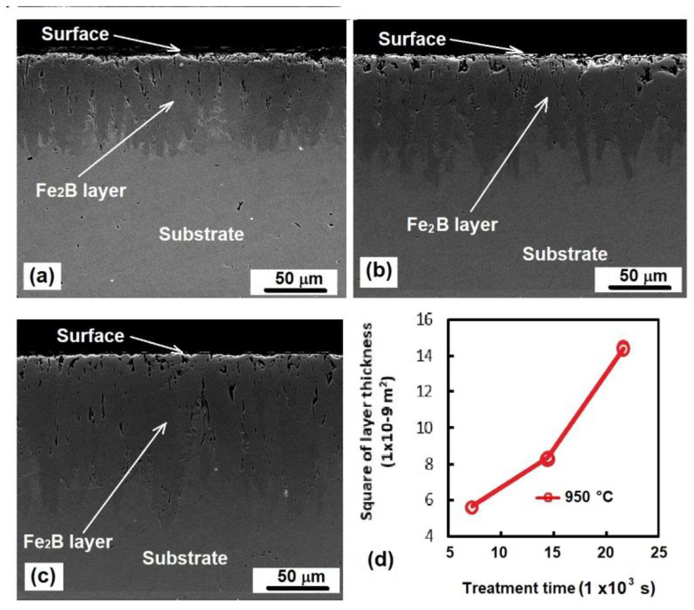
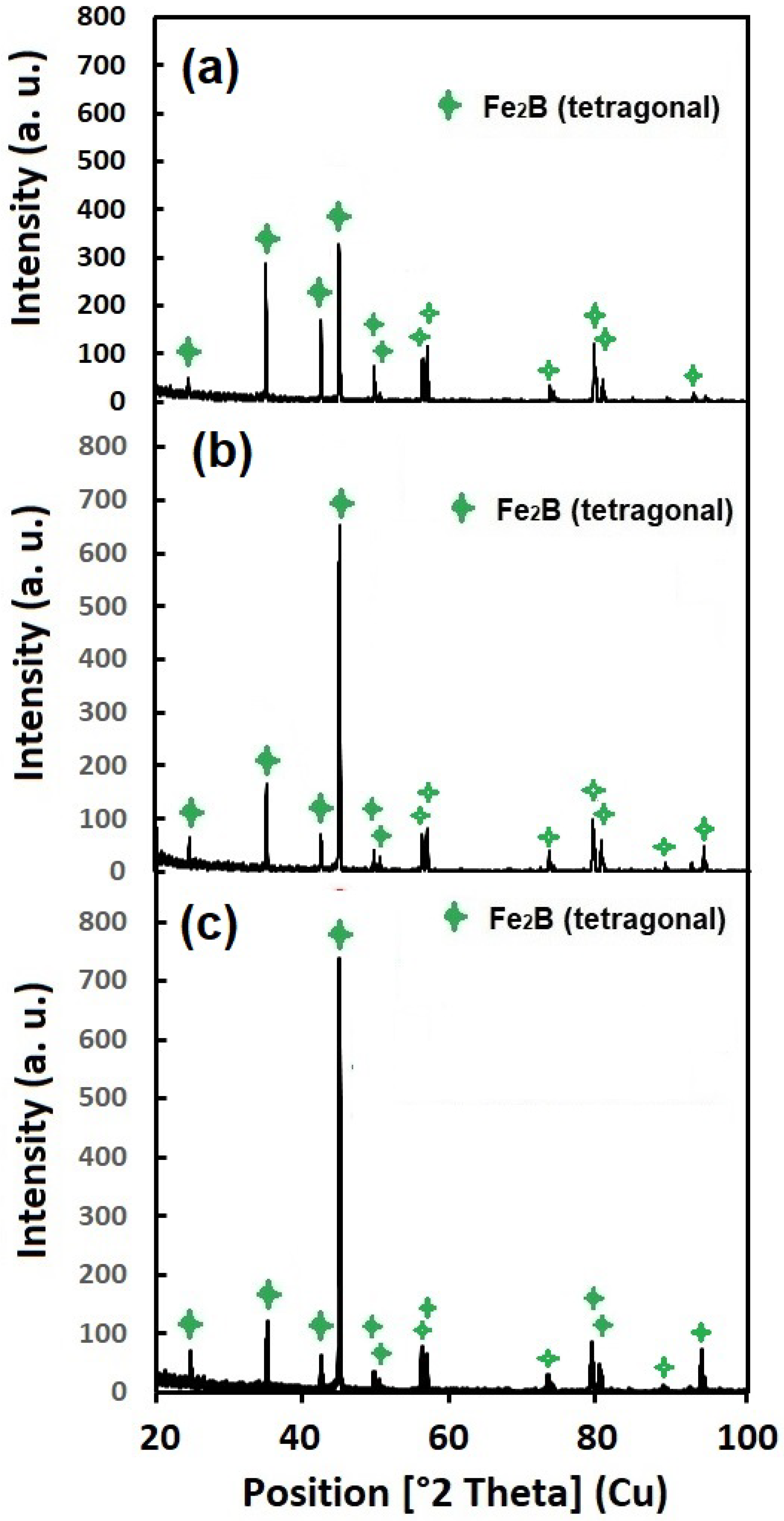
  • By applying the surface hardening treatment known as boriding to automotive crankshaft steel, well-consolidated monophasic boride layers with a saw-toothed morphology were obtained.
  • Because the treatment temperature remained constant, the growth of the boride layers was only dependent on the time of exposure, which allowed for the precise control of the experiments.
  • The hardness of the steel surface drastically increased, and the results indicate higher wear resistance because the coefficient of friction was reduced by at least 100%.
  • The results of the tribological tests indicate that the treated steel is more apt for facing wear conditions, especially under dry conditions where the boride layer acts as a solid lubricant.
  • The damage suffered by the WC ball during the pin-on-disk tests applied to the non-treated steel demonstrated the potential risk to Babbitt metal in cases where the lubrication system fails and the lubricant does not reach the crankshaft on time.

Author Contributions

Conceptualization, E.H.-S., D.H.-D., and R.T.-R.; Data curation, R.T.-R.; Formal analysis, E.H.-S.; Funding acquisition, E.H.-S.; Investigation, Y.S.-F.; Methodology, D.H.-D., J.G.M.-H., and R.C.-E.; Project administration, E.H.-S.; Resources, E.H.-S.; Supervision, E.H.-S.; Validation, L.A.L.-D. and C.O.-Á.; Visualization, D.H.-D.; Writing—original draft, D.H.-D., Y.S.-F., L.A.L.-D., C.O.-Á., and R.C.-E.; Writing—review and editing, E.H.-S. All authors have read and agreed to the published version of the manuscript.

Funding

This work was supported by research Grant 20231174 of the Instituto Politécnico Nacional in Mexico.

Institutional Review Board Statement

Not applicable.

Informed Consent Statement

Not applicable.

Data Availability Statement

The data that support the findings of this study are available from the corresponding author upon reasonable request.

Acknowledgments

The authors thank the Center of Nanosciences and Micro–Nano Technologies of the Instituto Politécnico Nacional for their cooperation. Additionally, they would like to thank the Universidad Autónoma de Coahuila and the Universidad de las Américas Puebla in México for their collaboration in developing this work.

Conflicts of Interest

The authors declare no conflicts of interest.

References

  1. Findik, F. Latest progress on tribological properties of industrial materials. Mater. Des. 2014, 572, 18–24. [Google Scholar] [CrossRef]
  2. García, B.S.; Muruzabal, T.C.; Royo, L.P.; Mata, J.S.; Íñigo, E.S. Interface patológica por fricción metal-metal y metal-polietileno, diferencias microscópicas. Rev. Esp. Cir. Osteoartic. 1996, 31, 171–176. [Google Scholar]
  3. Erdemir, A.; Eryilmaz, O.L. Chapter 16, Superlubricity in Diamond-Like Carbon Films. In Superlubricity; Elsevier Science: Amsterdam, The Netherlands, 2007; pp. 253–271. [Google Scholar]
  4. Hernández-Sanchez, E.; Chino-Ulloa, A.; Velázquez, J.C.; Herrera-Hernández, H.; Velázquez-Mancilla, R.; Carrera-Espinoza, R. Effect of Relative Humidity on the Tribological Properties of Self-Lubricating H3BO3 Films Formed on the Surface of Steel Suitable for Biomedical Applications. Adv. Mater Sci. Eng. 2015, 2015, 1–9. [Google Scholar] [CrossRef]
  5. Chen, Z.; Yu, X.; Ding, N.; Cong, J.C.; Sun, J.; Jia, Q.; Wang, C. Wear resistance enhancement of QT700-2 ductile iron crankshaft processed by laser hardening. Opt. Laser Technol. 2023, 109, 164519. [Google Scholar] [CrossRef]
  6. Freitas, B.J.M.; de Oliveira, V.A.; Gargarella, P.; Koga, G.Y.; Bolfarini, C. Microstructural characterization and wear resistance of boride-reinforced steel coatings produced by Selective Laser Melting (SLM). Surf. Coat. Technol. 2021, 426, 127779. [Google Scholar] [CrossRef]
  7. Duan, Y.; Wang, X.; Liu, D.; Bao, W.; Li, P.; Peng, M. Characteristics, wear and corrosion properties of borided pure titanium by pack boriding near α → β phase transition temperature. Ceram. Int. 2020, 46 Pt B, 16380–16387. [Google Scholar] [CrossRef]
  8. Wang, B.; Liu, B.; Zhang, X.; Gu, J. Enhancing heavy load wear resistance of AISI 4140 steel through the formation of a severely deformed compound-free nitrided surface layer. Surf. Coat. Tech. 2018, 356, 89–95. [Google Scholar] [CrossRef]
  9. Campos, I.; Farah, M.; López, N.; Bermúdez, G.; Rodríguez, G.; Velázquez, C.V. Evaluation of the tool life and fracture toughness of cutting tools, boronized by the paste boriding process. Appl. Surf. Sci. 2008, 254, 2967–2974. [Google Scholar] [CrossRef]
  10. Hernández-Ramírez, E.J.; Guevara-Morales, A.; Figueroa-López, U.; Campos-Silva, I. Wear resistance of diffusion annealed borided AISI 1018 steel. Mater. Lett. 2020, 277, 128–297. [Google Scholar] [CrossRef]
  11. Chino-Ulloa, A.; Hernandes-Alejandro, M.; Castrejón-Flores, J.L.; Cabrera-González, M.; Torres-Avila, I.P.; Velázquez, J.C.; Ruiz-Trabolsi, P.A.; Hernández-Sánchez, E. Development of Ultra-Low Friction Coefficient Films and Their Effect on the Biocompatibility of Biomedical Steel. Mater. Trans. 2019, 60, 1605–1613. [Google Scholar] [CrossRef]
  12. Alkan, S.; Günen, A.; Gülen, M.; Gök, M.S. Effect of boriding on tribocorrosion behavior of HSLA offshore mooring chain steel. Surf. Coat. Technol. 2024, 476, 130276. [Google Scholar] [CrossRef]
  13. Gok, M.S.; Küçük, Y.; Erdogan, A.; Oge, M.; Kanca, E.; Günen, A. Dry sliding wear behavior of borided hot-work tool steel at elevated temperatures. Surf. Coat. Technol. 2017, 328, 54–62. [Google Scholar] [CrossRef]
  14. Karakaş, M.S. Tribocorrosion behavior of surface-modified AISI D2 steel. Surf. Coat. Technol. 2020, 394, 125884. [Google Scholar] [CrossRef]
  15. Türkmen, I.; Yalamaç, E. Growth of the Fe2B layer on SAE 1020 steel employed a boron source of H3BO3 during the powder-pack boriding method. J. Alloys Compd. 2018, 744, 558–666. [Google Scholar] [CrossRef]
  16. Campos, I.; Oseguera, J.; Figueroa, U.; García, J.A.; Bautista, O.; Kelemenis, G. Kinetic study of boron diffusion in the paste boriding process. Mater. Sci. Eng. A 2003, 352, 261–265. [Google Scholar] [CrossRef]
  17. Ouyang, D.; Cui, X.; Lu, S. Growth kinetics of the FeB/Fe2B boride layer on the surface of 4Cr5MoSiV1 steel: Experiments and modelling. J. Mater. Res. Technol. 2021, 11, 1272–1280. [Google Scholar] [CrossRef]
  18. Sezgin, C.T.; Hayat, F. The effects of boriding process on tribological properties and corrosive behavior of a novel high manganese steel. J. Mater. Process. Technol. 2022, 300, 117421. [Google Scholar] [CrossRef]
  19. Von Matuschka, M.G. Boronizing, 1st ed.; Carl Hanser: Munich, Germany, 1980. [Google Scholar]
  20. Ozbek, I.; Bindal, C. Kinetics of Borided AISI M2 High-Speed Steel. Vacuum 2011, 86, 391–397. [Google Scholar] [CrossRef]
  21. ASTM E-384-05a; Standard Test Method for Microindentation Hardness of Materials. The American National Standards Institute: Washington, DC, USA, 2005.
  22. Laugier, M.T. New formula for indentation toughness in ceramics. J. Mater. Sci. Lett. 1987, 6, 355–356. [Google Scholar] [CrossRef]
  23. ASTM G 99-04a; Standard Test Method for Wear Testing with a Pin-on-Disk Apparatus. The American National Standards Institute: Washington, DC, USA, 2004.
  24. Kulka, M.; Makuch, N.; Dziarski, P.; Piasecki, A. A Study of Nanoindentation for Mechanical Characterization of Chromium and Nickel Borides’ Mixtures Formed by Laser Boriding. Ceram. Int. 2014, 40, 6083–6094. [Google Scholar] [CrossRef]
  25. Zhang, D.; Li, Y.; Du, X.; Fan, H.; Gao, F. Microstructure and Tribological Performance of Boride Layers on Ductile Cast Iron under Dry Sliding Conditions. Eng. Fail. Anal. 2022, 134, 106080. [Google Scholar] [CrossRef]
  26. Milinović, A.; Marušić, V.; Konjatić, P.; Berić, N. Effect of Carbon Content and Boronizing Parameters on Growth Kinetics of Boride Layers Obtained on Carbon Steels. Materials 2022, 15, 1858. [Google Scholar] [CrossRef] [PubMed]
  27. Martínez-Nopala, S.R.; Figueroa-Lopez, U.; Guevara-Morales, A.; Campos-Silva, I. Solid particle erosion resistance of borided AISI D2 steel. Mater. Today Commun. 2024, 38, 107887. [Google Scholar] [CrossRef]
  28. Hernández-Sanchez, E.; Rodriguez-Castro, G.; Meneses-Amador, A.; Bravo-Bárcenas, D.; Arzate-Vazquez, I.; Martínez-Gutiérrez, H.; Romero-Romo, M.; Campos-Silva, I. Effect of the anisotropic growth on the fracture toughness measurements obtained in the Fe2B layer. Surf. Coat. Technol. 2013, 237, 292–298. [Google Scholar] [CrossRef]
  29. Gencer, Y. Influence of Manganese on Pack Boriding Behaviour of Pure Iron. Surf. Eng. 2011, 27, 634–638. [Google Scholar] [CrossRef]
  30. Keddama, M.; Kulka, M.; Makuch, N.; Pertek, A.; Małdzinski, L. A kinetic model for estimating the boron activation energies in the FeB and Fe2B layers during the gas-boriding of Armco iron: Effect of boride incubation times. Appl. Surf. Sci. 2014, 298, 155–163. [Google Scholar] [CrossRef]
  31. Jain, V.; Sundararajan, G. Influence of the pack thickness of the boronizing mixture on the boriding of steel. Surf. Coat. Technol. 2002, 149, 21–26. [Google Scholar] [CrossRef]
  32. Quinn, J.; Quinn, G.D. Indentation brittleness of ceramics: A fresh approach. J. Mater. Sci. 1997, 32, 4331–4346. [Google Scholar] [CrossRef]
  33. Campos-Silva, I.; Flores-Jiménez, M.; Rodríguez-Castro, G.; Hernández-Sánchez, E.; Martínez-Trinidad, J.; Tadeo-Rosas, R. Improved fracture toughness of boride coating developed with a diffusion annealing process. Surf. Coat. Technol. 2013, 237, 429–439. [Google Scholar] [CrossRef]
  34. Stach, S.; Cybo, J.; Chmiela, J. Fracture surface—Fractal or multifractal. Mater. Charact. 2001, 26, 163–167. [Google Scholar] [CrossRef]
  35. Toktaş, G.; Korkmaz, S. Indentation fracture toughness of boronized unalloyed and alloyed ductile iron. Mater. Chem. Phys. 2023, 296, 127232. [Google Scholar] [CrossRef]
  36. Campos, I.; Rosas, R.; Figueroa, U.; Villa Velázquez, C.; Meneses, A.; Guevara, A. Fracture toughness evaluation using Palmqvist crack models on AISI 1045 borided steels. Mater. Sci. Eng. A 2008, 488, 562–568. [Google Scholar] [CrossRef]
  37. Rabinowicz, E. Friction, and Wear Materials; John Wiley & Sons, Inc.: New York, NY, USA, 1995. [Google Scholar]
  38. Yin, J.; Liu, R.; Zhang, R.; Lv, B.; Meng, X. A new tribo-dynamics model for engine connecting rod small-end bearing considering elastic deformation and thermal effects. Tribol. Int. 2023, 188, 108831. [Google Scholar] [CrossRef]
  39. Jiang, J.; Wang, Y.; Zhong, Q.; Zhou, Q.; Zhang, L. Preparation of Fe2B Boride Coating on Low-Carbon Steel Surfaces and Its Evaluation of Hardness and Corrosion Resistance. Surf. Coat. Technol. 2011, 206, 473–478. [Google Scholar] [CrossRef]
Figure 1. A schematic of the part of the automotive crankshaft where the samples were obtained.
Coatings 14 00716 g001
Figure 2. The indentation methodology employed to follow the guidelines of ASTM E384. dV is the Vickers diagonal.
Coatings 14 00716 g002
Figure 3. Cross-section of the boride layers exposed to boriding at 950 °C for (a) 2 h, (b) 4 h, and (c) 6 h. (d) Behavior of the layer’s thickness as a function of the treatment time.
Coatings 14 00716 g003
Figure 4. XRD patterns of samples exposed to 950 °C and treated for 2 h (a), 4 h (b), and 6 h (c).
Coatings 14 00716 g004
Figure 5. EDS assay for samples exposed to 950 °C for (a) 2 h, (b) 4 h, and (c) 6 h of treatment [11].
Coatings 14 00716 g005
Figure 6. Hardness profile (a) and Hardness behavior (b) for hardness measurement of treated samples.
Coatings 14 00716 g006
Figure 7. Pin-on-disk tracks and their corresponding WC ball damage, with an applied load of 2N for non-treated samples (g,h) and samples exposed to 2 h (a,b), 4 h (c,d), and 6 h (e,f) of treatment.
Coatings 14 00716 g007
Table 1. Chemical composition of automotive crankshaft steel (XRF analysis).
ElementCMnNiCrCuFe
%w.0.160.0690.140.2540.021Balance
Table 2. Layer thicknesses and values of constant of parabolic growth under different treatment conditions.
Treatment Time (s)Layer Thickness (µm)(m)K (m2·s−1)
720048.71 ± 7.244.87 × 10−51.297 × 10⁻¹²
14,40082.18 ± 10.658.22 × 10−5
21,600145.07 ± 11.051.45 × 10−5
Table 3. Fracture toughness values for the boride layers were obtained on the automotive crankshaft steel exposed to 950 °C for 6 h.
Treatment Time (h)l
(m)
g
(m)
Kc
(MPa·m1/2)
(l/g)Crack
Type
63.16 × 10−64.15 × 10−62.490.76Palmqvist
Table 4. CoF values and wear rate for borided and non-borided samples.
Treatment TimeVloss (mm3)Contact PressureWear RateCoF
(h)WC BallSample(GPa)(mm3·N−1·m−1)
Non-treated0.07140.009761.39.7 × 10−50.431 ± 0.014
20.01830.0013798.81.37 × 10−50.310 ± 0.078
40.00860.00112110.01.12 × 10−50.126 ± 0.013
60.02030.00109102.01.09 × 10−50.121 ± 0.008
Disclaimer/Publisher’s Note: The statements, opinions and data contained in all publications are solely those of the individual author(s) and contributor(s) and not of MDPI and/or the editor(s). MDPI and/or the editor(s) disclaim responsibility for any injury to people or property resulting from any ideas, methods, instructions or products referred to in the content.

