1. Introduction
With the continuous development of packaging technology, from traditional wafer-level packaging to today’s 3D packaging, the electrical performance of the module has been effectively improved. However, the interface thermal resistance is still the key to restricting power. High-power equipment must have a heat dissipation layer to match [
1,
2,
3,
4,
5]. Therefore, high-thermal conductivity composites have attracted more and more attention. Thermal management technology has become the key to upgrading equipment quality. The arc of the composite insulator will generate a lot of heat during the operation of the DC high-voltage power grid, and the heat accumulation will lead to the aging of the insulator, which will not provide the proper insulation performance. Therefore, the heat dissipation problem of electronic components and electrical equipment needs to be solved urgently [
6,
7].
Generally, heat is emitted through the radiator, but there are a large number of voids between the components and the radiator, so it is necessary to transfer heat between the components and the radiator with high thermal conductivity materials. The thermal conductivity of metal materials is high, but the insulation performance is poor. Ceramic materials have the advantages of good insulation, high strength, good thermal stability, and a low expansion coefficient, but the sintering size of ceramics is difficult to unify, and the cost is high. Polymers have a light weight, high stability, high specific strength, electrical insulation, high modulus, low cost, and good processability, and are usually used to manufacture thermal interface materials.
Nowadays, the widely accepted classification of thermally conductive polymers is based on the preparation method (effective thermally conductive components); that is, the so-called intrinsic thermally conductive polymers and filled thermally conductive polymers [
8]. The thermal conductivity of intrinsic polymer thermal conductive materials is mainly related to crystallinity, molecular chain structure, and molecular orientation. By applying external forces (external magnetic field, electric field, pressure field, etc.), the molecular chain structure is adjusted, the molecular chain segment is rearranged, and the molecular chain is improved. The orderliness and crystalline regions obtain a physical structure with complete crystallinity or uniform orientation, thereby improving the thermal conductivity of the composite [
9,
10]. However, the preparation process for such materials is relatively complex, and large-scale production is difficult. Adding high-thermal conductivity fillers to the matrix is an efficient and easy-to-produce method [
11]. The increase in thermal conductivity of the filled thermally conductive polymer is mainly provided by the filler. Therefore, the addition of fillers, the shape and size of particles, the dispersion and orientation of particles, the interface effect, and other factors have a great influence on the thermal conductivity of the composites. At present, much research on filled thermal conductive materials is focused on the development and efficient application of new thermal conductive fillers. Zhao [
12] found that the coordination of graphene foam (GF) and multilayer graphene nanosheets (MGFs) can significantly improve the thermal conductivity of composites. The thermal conductivity of MGFs/GF/PDMS composites increased to 1.08 W/(m·K) at 2.7 vol% MGFs. Yang [
13] prepared benzenetricarboxylic acid grafted multi-walled carbon nanotubes (BTC-MWCNTs)/epoxy resin composites by mixing tetrahydrofuran, pyromellitic acid-grafted multi-walled carbon nanotubes, and epoxy resin. The results show that BTC-MWCNTs can effectively reduce the interfacial thermal resistance of carbon nanotubes, improve the dispersion of fillers in the system, and form more thermal conduction paths. The thermal conductivity of the composites can be increased to 0.96 W/(m·K).
Due to the ultra-high thermal conductivity of graphene, but also to its good conductivity, in order to obtain high thermal conductivity insulation coatings, alumina/waterborne polyurethane composites were prepared by mechanical blending. By changing the amount of alumina added to the composite material, the effects of the microstructure, thermal conductivity, and other properties of the composite material were investigated. Subsequently, on the basis of the previous step, the optimal addition amount was determined, and the alumina/graphene/waterborne polyurethane composite material was further prepared to explore the optimal filler ratio. The experiments show that the amount of alumina added is 60 wt%. When the addition amount of graphene is 2 wt%, the thermal conductivity of the ternary composite reaches 1.049 W/(m·K), which is significantly improved compared with the single filler filling. The excellent performance of the composite material can provide new ideas and technical support for the heat dissipation design of electronic devices.
2. Experimental Procedure
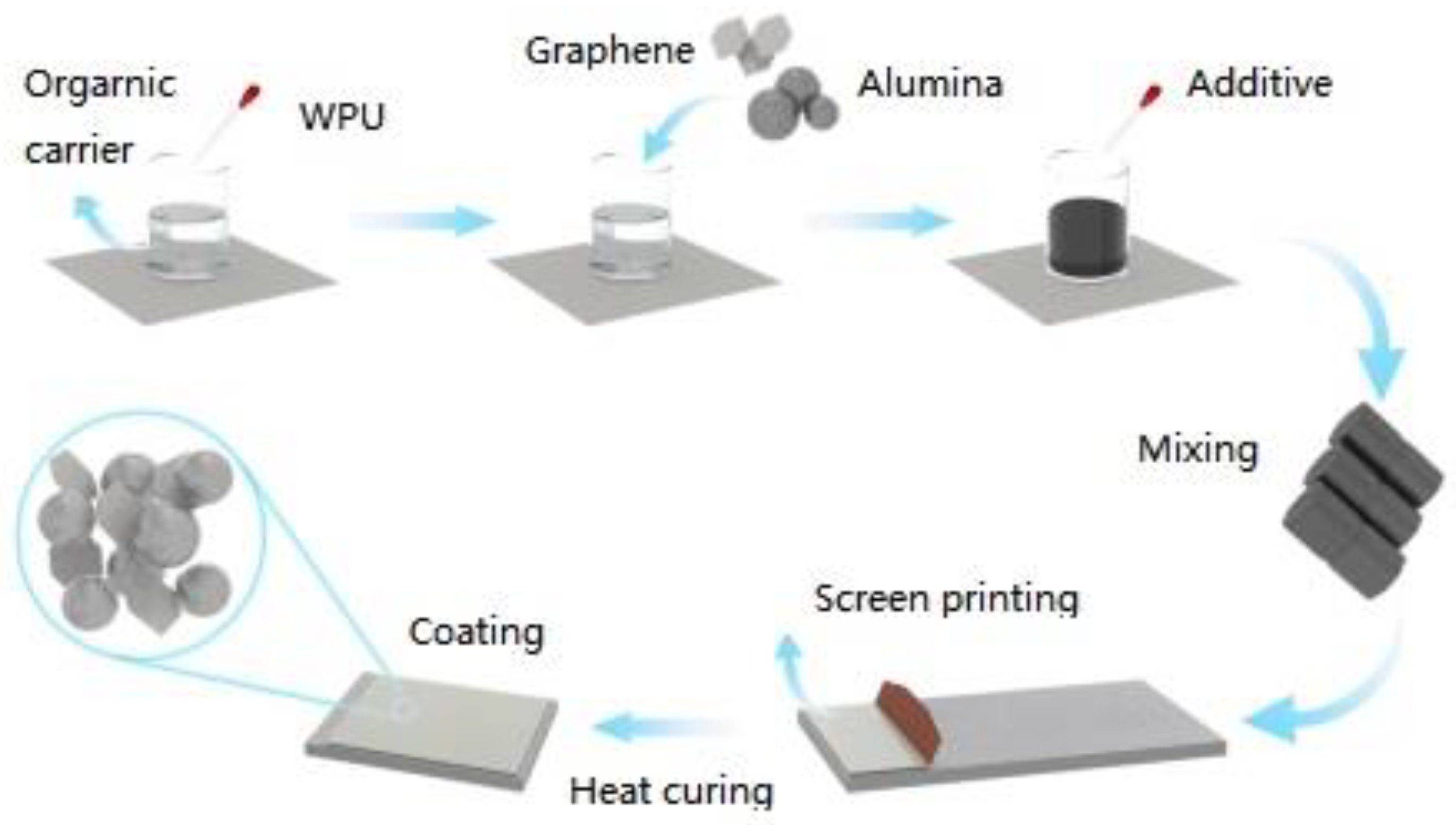
Figure 1 shows the preparation process of Al
2O
3/Gr/WPU composites. The resin and diluent were mixed in proportion and mechanically stirred for 20 min, the leveling agent and part of the defoaming agent were added, and the mixture was fully stirred and mixed. The alumina and resin carriers were mechanically stirred for 10 min to mix evenly, and the mixed slurry was ground by a three-roll grinder. The grinding gap was reduced from 10 μm to 1 μm in turn. After three rollers, the remaining defoaming agent was added, and the vacuum treatment was carried out in the vacuum drying box to remove the internal bubbles. The grinding slurry was printed on the stainless-steel substrate by a screen-printing machine and dried to obtain different thermally conductive and insulating composites.
In this paper, Al2O3/WPU composites with filler contents of 40 wt%, 50 wt%, 60 wt%, and 70 wt% were prepared. In order to further explore the way to improve the thermal conductivity and obtain the best packing stacking method, the content of Al2O3 was fixed at 60%, while the graphene was 0.5 wt%, 1 wt%, 1.5 wt%, 2 wt%, respectively. Research manuscripts reporting large datasets that are deposited in a publicly available database should specify where the data have been deposited and provide the relevant accession numbers. If the accession numbers have not yet been obtained at the time of submission, please state that they will be provided during review. They must be provided prior to publication.
Scanning electron microscopy (SEM, Quanta-450-FEG + X-MAX50, Thermo Fisher Scientific (FEI), Waltham, MA, USA) was used to observe the surface morphology of the composite material after the sputtering coating was coated with a thin gold layer. The element distribution of the sample was tested by an energy dispersive spectrometer (EDS). The unit breakdown voltage of the sample was tested by a resistive voltage tester (RK7110, Shenzhen Meiruike Electronic Technology Co., Ltd., Shenzhen, China). The positive probe of the withstand voltage tester was pressed on the surface of the thermally conductive material coating, and the negative probe of the withstand voltage tester was clamped on the substrate to read out the breakdown voltage value. The breakdown voltage per millimeter of the composite material is calculated according to the thickness of the sample. The insulation resistance was tested using a high-resistance meter. The scratch tester (WS-2005, Lanzhou Zhongke Kaihua Technology Development Co., Ltd., Lanzhou, China) was used to test the adhesion of the thermally conductive insulation coating, and the scratches were observed by the super-depth field microscope (VHX-5000, KEYENCE (CHINA) Co., Ltd., Shanghai, China). In order to explore the improvement effect of graphene on the corrosion resistance of the coating, the wettability of the thermal insulation coating was tested by the contact angle tester. In this experiment, the wettability of the sample was tested by the contact angle tester (JC2000C1, Shanghai Zhongchen Digital Technology Equipment Co., Ltd., Shanghai, China). The corrosion resistance of each coating was tested by an electrochemical workstation (CS). The coating has been cut into a 1 cm × 1 cm square sample with a working area of 1.0 cm
2. The corrosion resistance of conductive adhesive coating was tested in a 3.5% NaCl solution using a three-electrode system, with the coating as the working electrode, Hg/Hg
2Cl
2 electrode as the reference electrode, and platinum plate as the auxiliary electrode. The frequency range in EIS testing is 0.01 Hz to 100 kHz, with an AC amplitude of 5 mV; the polarization curve scanning rate is 10 mV/s, and the scanning positioning voltage range is −1.5~−0.8 V. All the above tests were conducted at room temperature. The thermal conductivity tester (DRP-II) was used to test the thermal conductivity of the composite material by the plate steady state method, and the thermal conductivity of the sample was calculated according to the Formula (1).
where
λ is the thermal conductivity of the sample, M is the quality of the cooling plate,
C is the specific heat of the cooling plate, Δ
T is the temperature difference of the cooling plate, Δ
t is the temperature difference of the cooling plate,
hc is the thickness of the heat sink,
RC is the diameter of the cooling plate, and
hB is the thickness of the sample.
T1 and
T2 are heating plate temperatures and cooling plate temperatures, respectively.
RB is the sample diameter.
3. Results
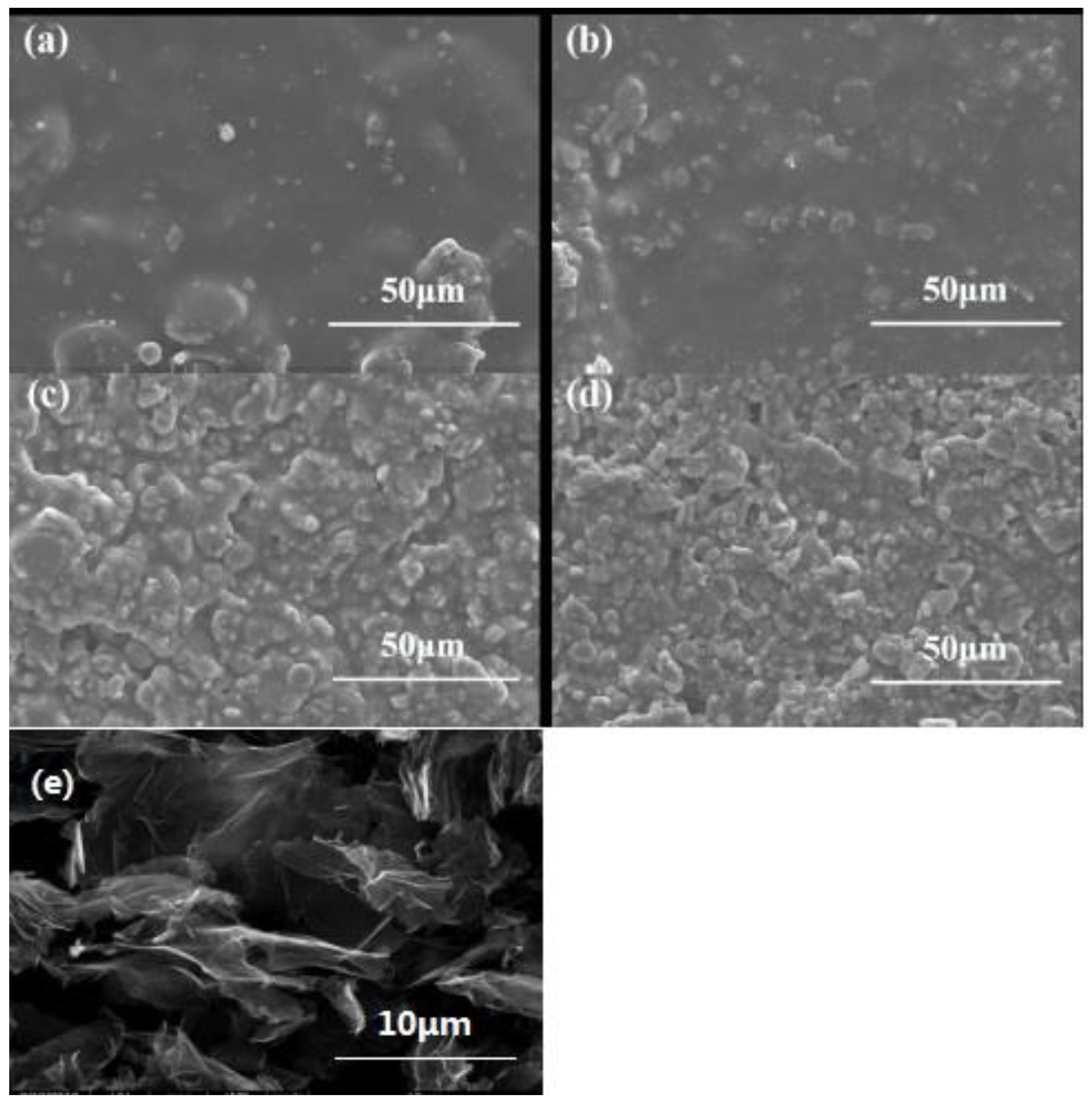
In order to analyze the effect of different contents of alumina on the microstructure of the composite powder coating,
Figure 2 shows the SEM images of polyurethane resin emulsion composites with different Al
2O
3 contents and graphene. It can be seen from the figure that the Al
2O
3 particles are evenly distributed in the polyurethane resin. In the figure, it can be observed that the content of Al
2O
3 increases gradually, there is obvious contact between the particles, and the thermal conduction path has been formed. It can be seen from the diagram that with the increase in alumina content, the coating is relatively densest. It shows that alumina powder is crosslinked with waterborne polyurethane under leveling curing, Al
2O
3 particles are filled into the micropores between the resins, and the active groups on the surface are crosslinked with the active groups in the resin or curing agent molecules, which plays a “closed pore” role in the micropores and enhances the compactness of the coating film. However, as the alumina content continues to increase, the cracks in the coating gradually increase. When the Al
2O
3 content is 70 wt%, the closed hole reaches its maximum, which may be due to the fact that alumina has been added to the maximum filling amount. In this paper, when the filler is added to 70 wt%, it is further revealed that the filling amount of inorganic particles has a great relationship with the type of resin. At this ratio, although silk printing can be carried out, the surface layer is uneven and there are a large number of holes, so the follow-up study is carried out with a 60 wt% filling amount.
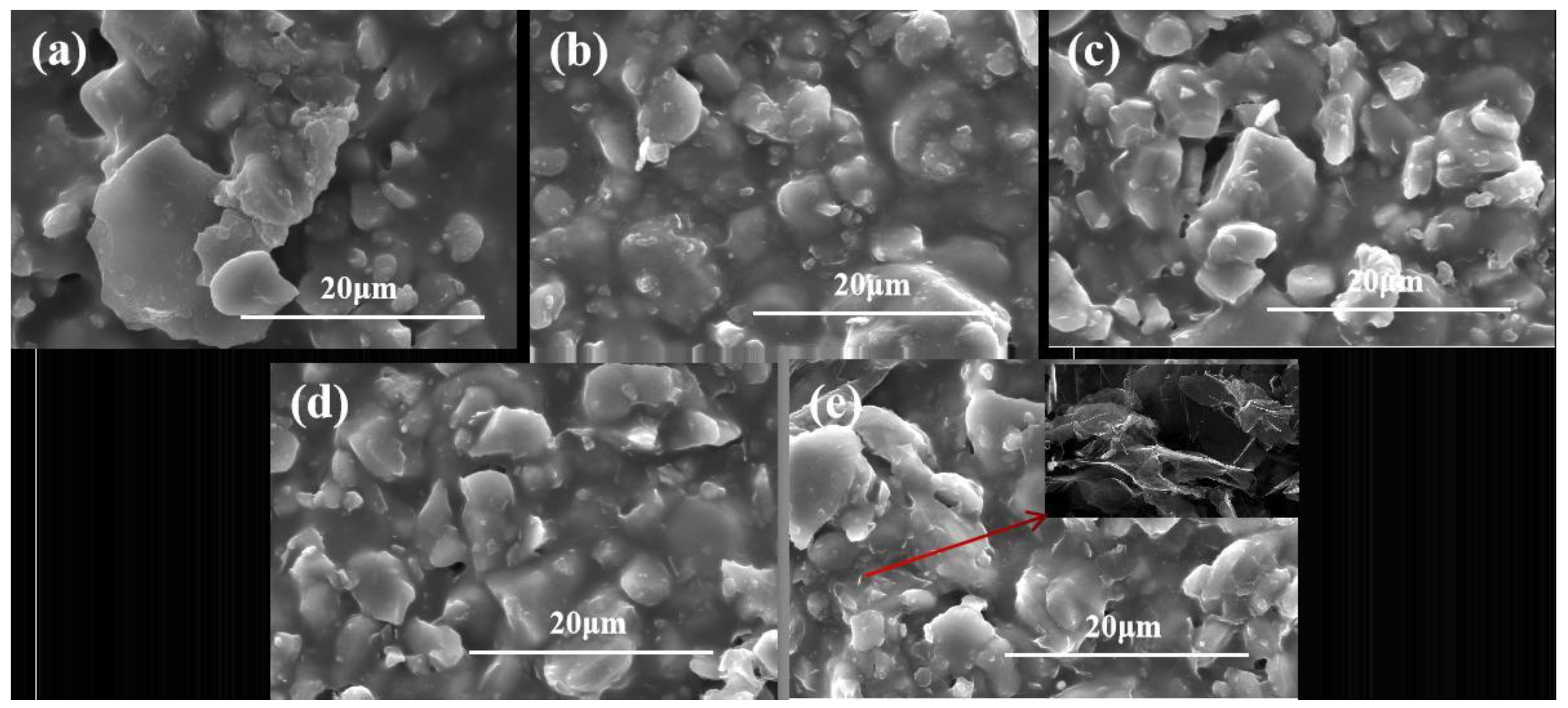
Figure 3 shows the microscopic images of composite coatings with different graphene additions. In
Figure 3a–e, the SEM microstructure of WPU/Al
2O
3-60 wt% composites filled with graphene is shown. The content of graphene is increased from 0.5 wt% to 2 wt%. In
Figure 3a, there is no obvious graphene. As the content of graphene in the resin matrix increases, the microstructure of the composite coating becomes rough, and some flake graphene appears on the surface of the coating. When the graphene content is 2wt.% it can be observed that the graphene sheet is embedded in the polymer. Al
2O
3 and graphene rarely extend and intersect in detail, and most of them are chimeric contacts, which is expected to further improve their thermal conductivity.
Table 1 shows some of the basic parameters required. The thermal conductivity of the material is calculated by the thermal conductivity model, as shown in
Table 2. The WPU/Al
2O
3-60 wt% system is regarded as a phase, and graphene is the second phase for theoretical calculation. The thermal conductivity of the composite material can be calculated by the thermal conductivity model, as shown in
Table 3.
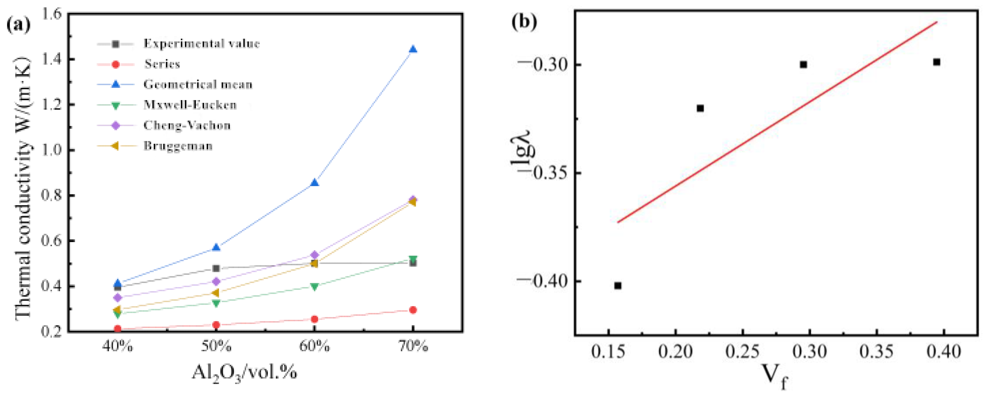
Figure 4 shows the thermal conductivity of composites with different filler contents. The Y. Agari model is also applicable to the study of this system for fitting, as shown in
Figure 4b.
The thermal conductivity test results of the single-filler composite material are shown in
Figure 4a. With the increase in Al
2O
3 content, the thermal conductivity of the composite material shows a continuous growth trend. This is because when the filler content is small, the interaction between the thermally conductive fillers is small in the resin relative to the island. However, with the increase in Al
2O
3 content, the probability of the thermally conductive fillers in the polymer matrix forming a path increases, and it is easier to form a thermally conductive path, thereby increasing the thermal conductivity. The increase in the thermal conductivity of the 70 wt% formula is less than that of the 60 wt% formula. According to the percolation value theory, the percolation value under this system is 60 wt%. When the filling amount exceeds 60 wt%, the thermal conductivity of the composite material maintains a low growth rate.
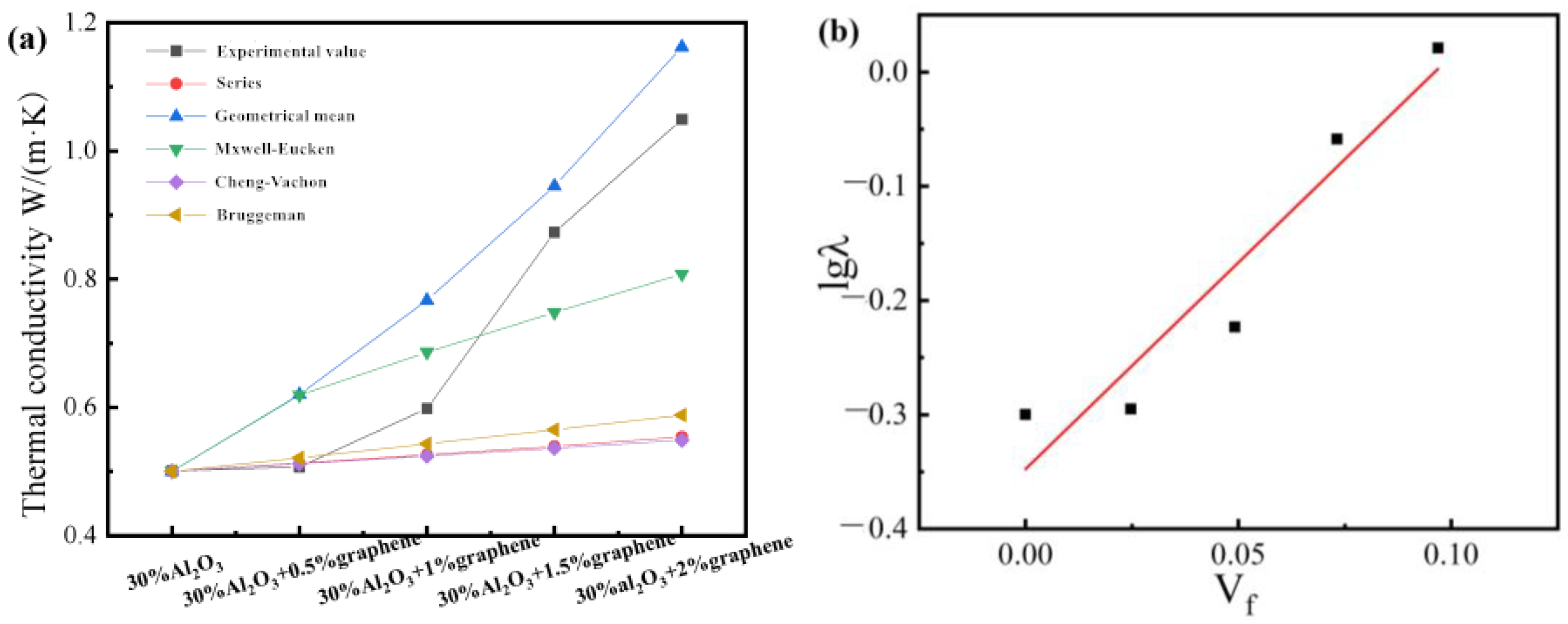
The co-doping of different fillers is an effective method to improve the thermal conductivity of polymer composites.
Figure 5 the thermal conductivity of composites with different amounts of graphene added. In
Figure 5b, according to the intercept and slope calculation, C
1 = 2.64 and C
2 = 1.42. In order to explore the synergistic effect between Al
2O
3 and Gr, different contents of graphene were added on the basis of an Al
2O
3 content of 30 wt%. Finally, the thermal conductivity of the composites with different graphene additions was obtained, as shown in
Figure 5. It can be seen that with the increase in graphene filling amount in the composite system, the thermal conductivity of the ternary system is basically the same as that of the Al
2O
3-filled pure polyurethane composite system, and the growth trend of the two is basically the same. However, after the addition of graphene, the curve deviates significantly upward, indicating that there is a synergistic effect between the two thermally conductive fillers. When the amount of graphene added is 2 wt%, the thermal conductivity curve of the composite material increases greatly, indicating that the synergistic thermal conductivity between the fillers is obvious. This shows that the synergistic effect of thermal conductivity is related to the amount of graphene added.
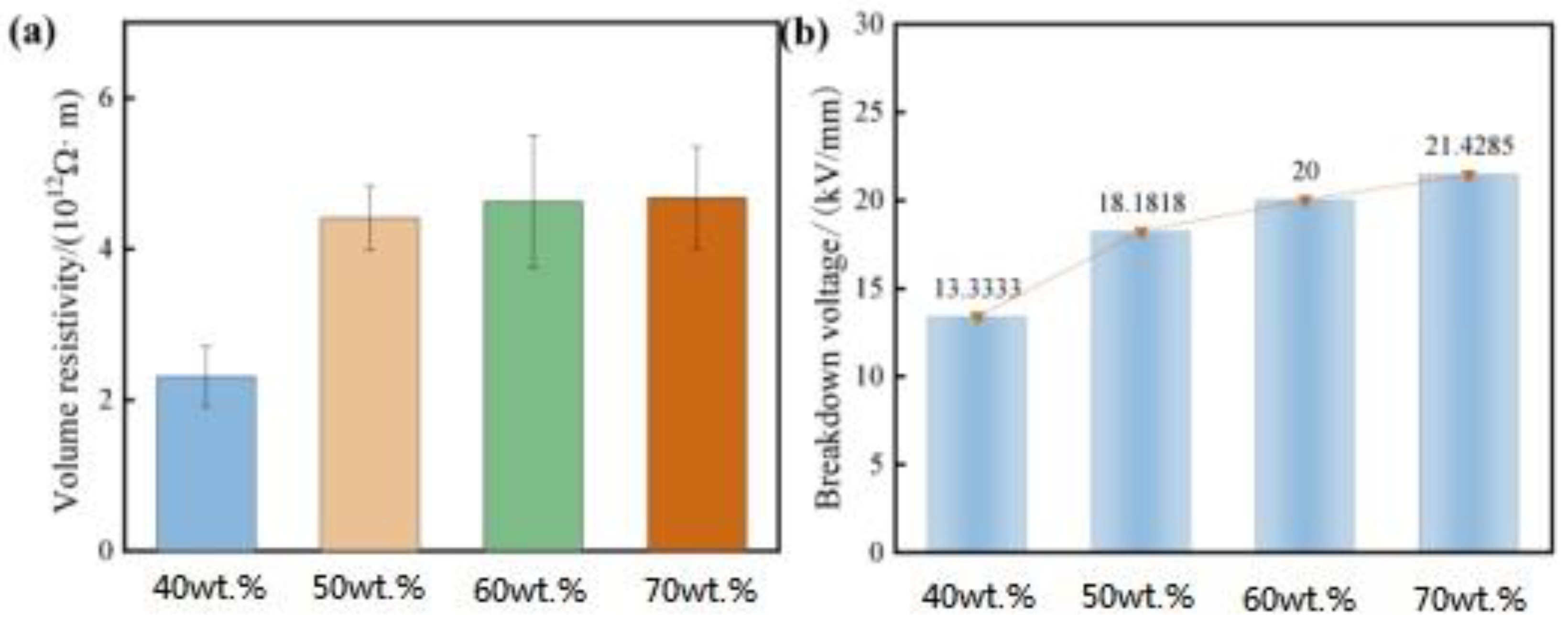
Insulation performance is an important indicator for the selection of electronic device materials.
Figure 6 shows the insulation performance (insulation resistance and breakdown voltage) of resin composites with different filling amounts. From
Figure 6, it can be seen that with the increase of Al
2O
3 content from 40 wt% to 70 wt%, the volume resistivity and breakdown voltage of the composites increase gradually with the increase of the content, which indicates that the addition of Al
2O
3 has a positive effect on the insulation performance of the system. Considering that Al
2O
3 itself has good insulation performance, when the amount of alumina reaches the saturation point, that is, when the amount of alumina is about 10 wt%, alumina no longer acts as a filler but is distributed as the main component in the resin carrier [
14]. Therefore, when the ratio increases, the composite is no longer a simple resin/alumina mixture but a new type of polymer ceramic material. With the increasing amount of alumina added, the organic polymer continues to change in the direction of polymer ceramics, and the insulation properties of the composites also increase.
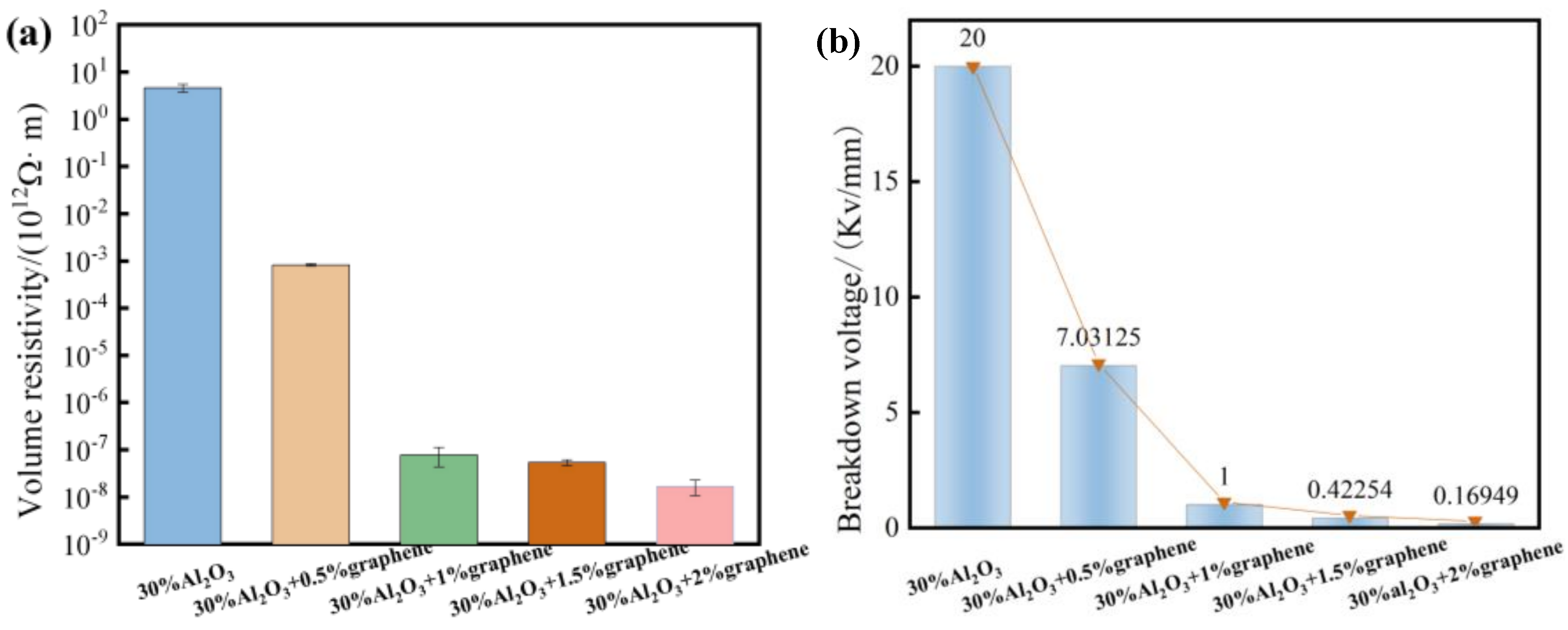
Figure 7 shows the insulation properties (insulation resistance and breakdown voltage) of different Gr-filled WPU composites. When the graphene content is 0.5 wt%, it shows the good insulation performance. At this time, the graphene filler is fully dispersed inside the composite material, the overall addition amount is small, and no conductive path is formed. With the increase in alumina filling amount, the viscosity of the slurry increases, the interface defect also increases, and the breakdown strength decreases.
The volume resistivity of the composites decreases by 8–9 orders of magnitude, from 2.3 × 10¹²Ω · m to 9.1 × 10⁵Ω · m, due to the good conductivity of graphene, and its three-dimensional network structure is conducive to the formation of conductive networks. Although the increase in graphene will cause the breakdown voltage of the composite material to decrease, the decrease is not large, indicating that the prepared composite material still has good insulation performance. On certain occasions, graphene and alumina can be compounded into thermally conductive and insulating fillers, which provides a new application for carbon materials in the field of thermal conductivity and insulation.
As an important part of the slurry, the amount of filler has an important influence on the performance of the coating. Based on the above research, WPU-3627 was used as the resin carrier, and the amount of filler was 40 wt%, 50 wt%, 60 wt% and 70 wt%, respectively.
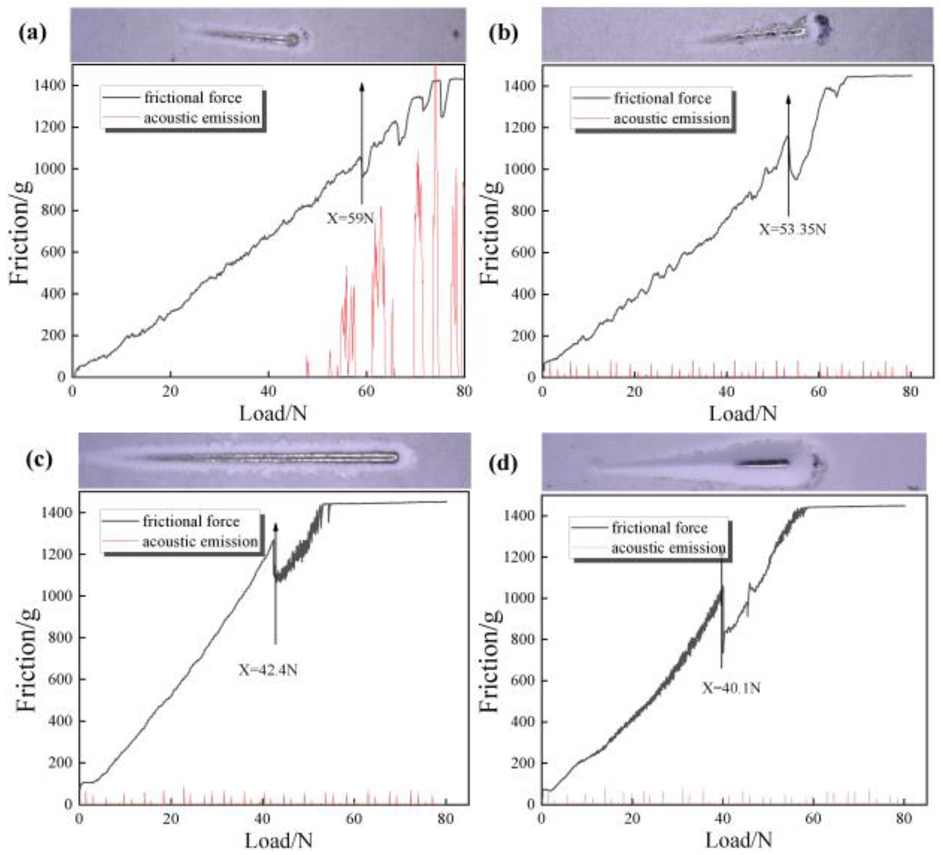
Figure 8 shows the metallographic photographs of composites prepared with different filler contents. It can be seen from the scratch morphology in
Figure 8a that the scratch becomes wider with the increase in load, and the scratch pit appears when the failure occurs. It shows that the adhesion of the coating is better when 40 wt% Al
2O
3 is added. At this time, when the load increases to 59 N, the coating begins to fail. In
Figure 8b, when the filler content is added to 50 wt%, the front and rear ends of the scratches and the shedding appear, and there is also a small amount of tissue accumulation on both sides. It can be seen from the bonding force test results that the critical load at this time is 53.35 N; in
Figure 8c, when the filler content is added to 60 wt%, the binding force is 42.4 N. With the continuous increase in alumina content, the two sides are scattered and show small flake spalling. At this time, there is a large amount of stress at the interface, and adhesion is continuously reduced.
Figure 8d shows that when the filler content is 70 wt%, the scratch is furrow wear, and the critical load is only 40.1 N. The main reason for the scratch is that when the resin ratio is high, the gap of the slurry will be filled with resin, and the particle dispersion is good, so the adhesion of the coating is increased. However, due to the addition of fillers, the proportion of resin in the coating will be relatively reduced, and the polar groups that form chemical bonds between the resin and the substrate will be reduced, resulting in a decrease in the force between the coating and the substrate, which is more likely to be scratched. Therefore, the adhesion will decrease with the increase in alumina. When subjected to stress shock, the polyurethane molecular chain is easy to break, and part of the broken chain segment is detached from the substrate, causing grooves or other damage. Even when the content is 70 wt%, the adhesion of the coating is reduced to 40.1 N. This is because as the content of alumina particles increases, the proportion of polymer in the coating decreases, and the density of the crosslinking network decreases, or too many alumina particles agglomerate, forming defects between the polymer and the alumina particles, resulting in a decrease in the adhesion between the coating and the stainless steel substrate.
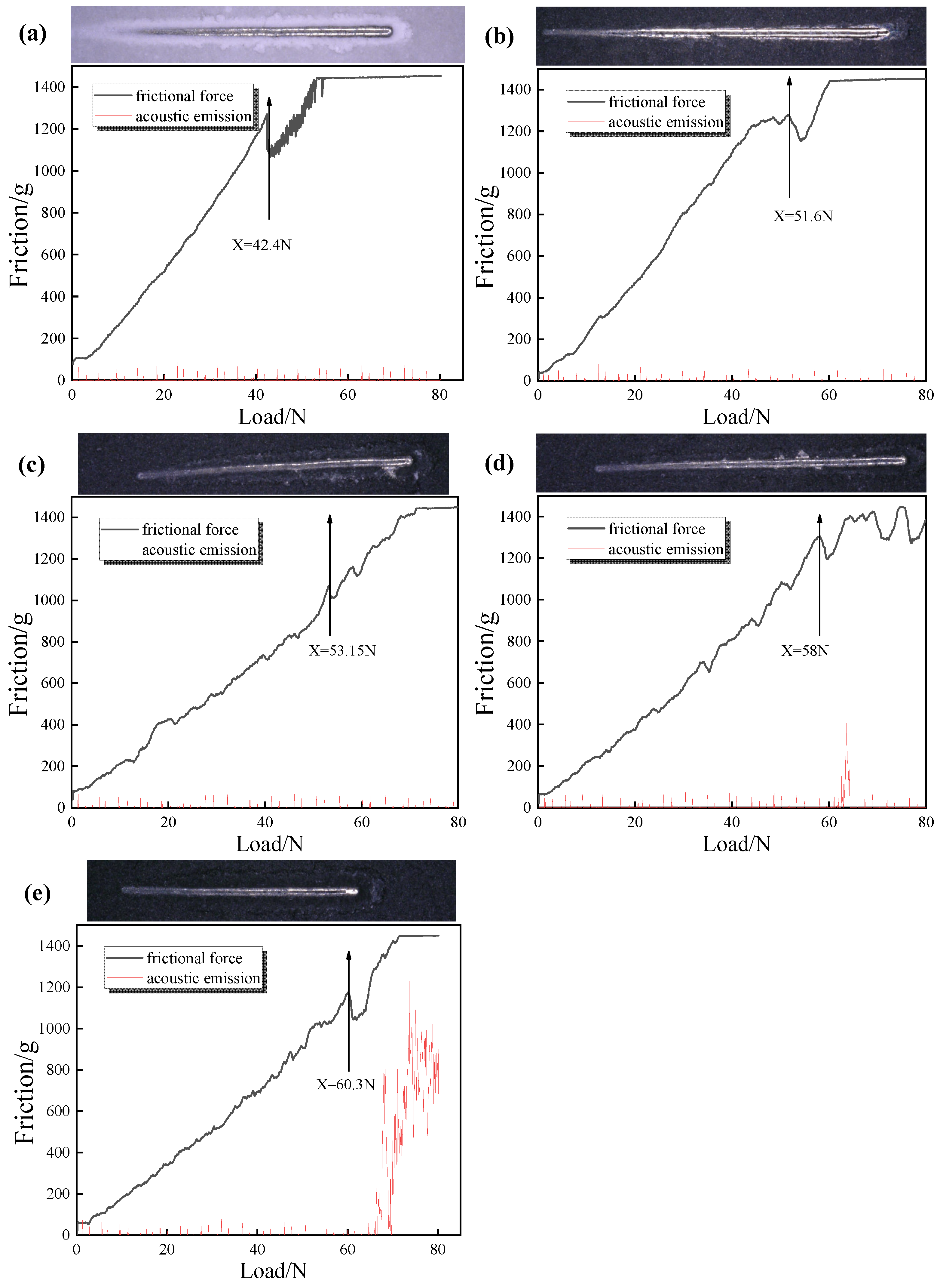
Figure 9 shows the bonding strength and scratch diagram of composites with different Gr content. The adhesion of the composite coating with 0 wt% graphene is 42.4 N. Combined with the scratch morphology of the attached figure in
Figure 9a, it is found that there is obvious crack propagation around the scratch. In
Figure 9b, the bonding force of the composite coating with 0.5 wt% graphene content is 51.6 N, the cracks around the scratches are significantly reduced, and the adhesion is significantly increased. It can be seen from the adhesion test results of graphene that the addition of graphene has a positive effect on the adhesion of the system. It is considered that although the addition of graphene still hinders the curing and crosslinking of the waterborne resin emulsion, the structure of graphene is a lamellar overlapping structure, and the graphene structure plays a role in sharing the external pressure. At this time, the effect of graphene on strengthening and dispersing the external force is much greater than that on the curing crosslinking degree of the resin, so the adhesion increases with the increase in graphene content. In
Figure 9c–e, the binding force of the thermally conductive composite material increases, in turn, and the scratch crack propagation becomes smaller and smaller. Due to the enhanced dispersion stress of graphene, the adhesion of the composite coating becomes better and better with the increase in graphene content.
Figure 10 and
Figure 11 are the electrochemical test diagrams of the coatings prepared with different contents of alumina and the thermally conductive coatings added with different graphene, respectively.
Table 4 shows the corrosion potential and corrosion current density of the polarization curve in
Figure 10a.
Table 5 shows the corrosion potential and corrosion current density of the polarization curve in
Figure 11a.
The electrochemical test diagram of polyurethane thermal insulation coatings with different alumina content is shown in
Figure 10, and
Figure 10a is the polarization curve of coatings with different amounts in a 3.5 wt% NaCl solution. The self-corrosion potential of thermal conductive materials prepared by adding 40 wt%, 50 wt%, 60 wt% and 70 wt% is −0.175 V, −0.165 V, −0.158 V and −0.149 V, respectively, and the corrosion potential of 70 wt% is the largest. The more positive the self-corrosion potential, the better the corrosion resistance of the coating. The self-corrosion currents were 3.47 × 10
−2 A/cm
−2, 3.09 × 10
−3 A/cm
−2, 1.78 × 10
−2 A/cm
−2, and 1.74 × 10
−2 A/cm
−2, respectively. The smaller the self-corrosion current, the smaller the corrosion rate and the slower the corrosion process. In electrochemical corrosion, Al
2O
3 has more corrosion resistance than polymers. Because Al
2O
3 can form a dense protective layer inside the coating, Cl-ions cannot be quickly corroded to the substrate. When the content of Al
2O
3 increases, the corrosion protection of the substrate increases at the same time.
Figure 10b is the Nyquist diagram. It can be seen that the diameter of the capacitive reactance arc is the largest when the amount of alumina is 70 wt%, and the diameter of the capacitive reactance arc is the smallest when the amount of alumina is 40 wt%. It shows that the coating with 60 wt% alumina content has better corrosion resistance.
Figure 9c is a bode mode diagram, and the impedance modulus is around 10
5 Ω · cm
2.
Figure 10d is a bode phase diagram, from which it can be seen that the samples have only one time constant. The phase angle curve of the 70 wt% alumina coating is wider at the phase peak, and the phase angle is closer to 90°, which is consistent with the results of the above polarization curve measurement.
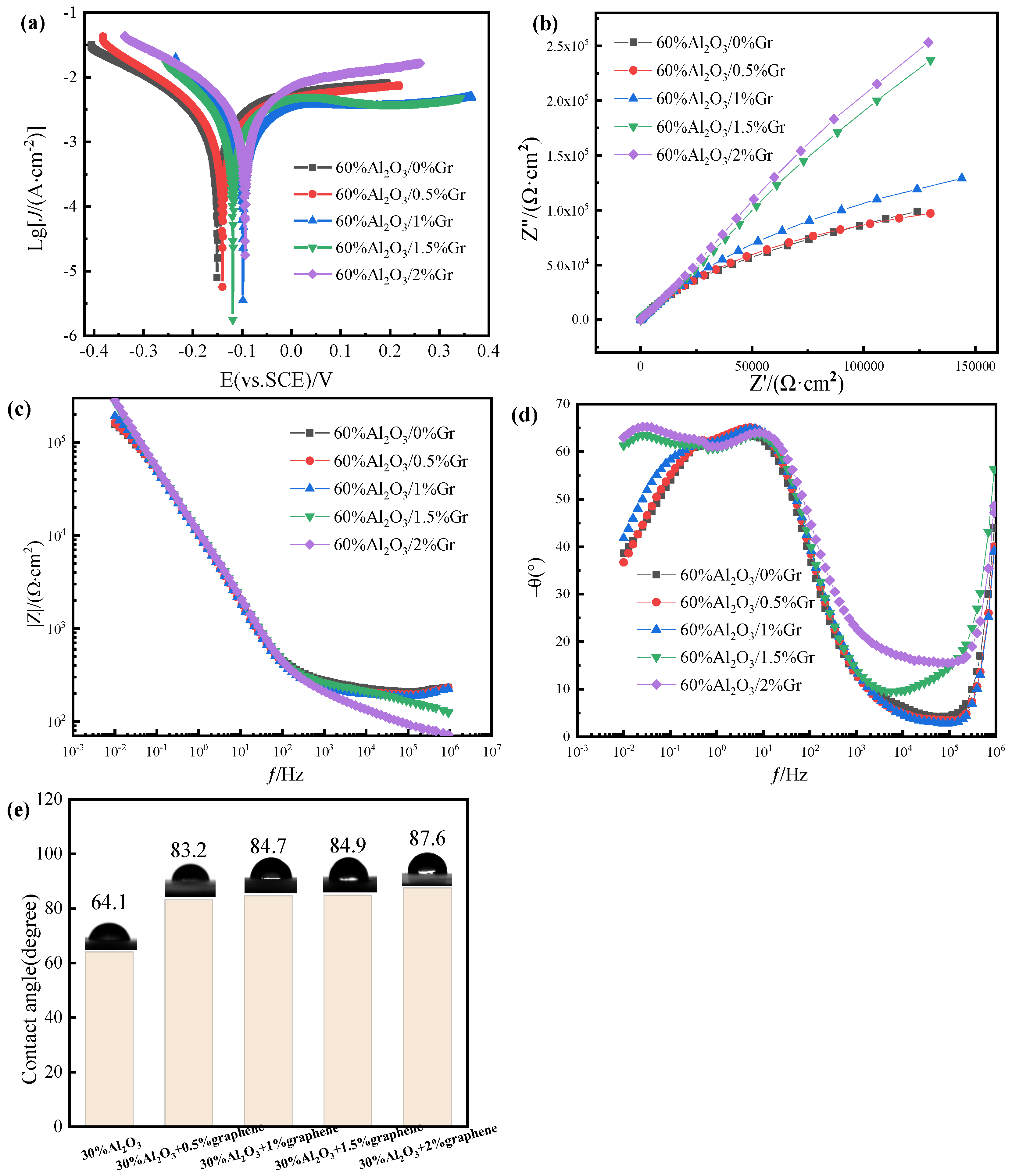
Figure 11 shows the electrochemical test diagram of Gr-doped WPU/Al
2O
3-60 wt%.
Figure 11a is the Tafel curve of the coating prepared with different graphene additions. It can be seen from the diagram that the corrosion potential of the 2 wt% Gr composite coating is the largest; E
corr = −0.94 V. The corrosion potential of pure WPU/Al
2O
3 coating is the smallest, which indicates that the corrosion resistance of WPU/Al
2O
3 composite coating is improved after doping graphene. Considering the hydrophobic structure of graphene, the improvement of corrosion resistance may be related to the hydrophobic properties of graphene. The contact angle test of the coating added with graphene was carried out. As shown in
Figure 11e, the contact angle of the coating increased gradually after the addition of graphene. This is because graphene itself has strong hydrophobic properties. Graphene produces air bags inside the coating. The air bags have a repulsion effect on water molecules, which hinders the contact between water molecules and the substrate, and the corrosion resistance becomes improved. Secondly, because of the filling effect of graphene, the maze effect is produced, which prolongs the invasion path of the corrosive medium, so it has strong impermeability and corrosion resistance.
Figure 11b is the impedance spectrum. The radius of the capacitive arc can reflect its size. The larger the radius of the capacitive arc in the figure, the higher the impedance and the better the corrosion resistance of the coating. It can be seen from the figure that the capacitive arc radius of the coatings with different Gr additions is different. The radius of curvature of the capacitive arc of the coating without graphene is the smallest. With the addition of graphene, the radius of the capacitive arc also increases. The capacitive arc of the 2 wt% graphene-modified composite coating is the largest, and the corrosion resistance is the best. It can be seen from
Figure 11c that the impedance of the coatings with different graphene additions has the same change rule in the low frequency region, and gradually decreases and tends to be stable with the development of the corrosion process. The coating with 2 wt% graphene has the highest impedance modulus at the minimum frequency, indicating that its corrosion resistance is the best. From
Figure 11d, it can be seen that the range at the maximum phase angle of 2 wt% graphene coating is wider. The phase angle is closer to 90°, indicating that the corrosion protection effect of the coating is the best after adding 2 wt% graphene.


