Article

The Influence of Nitrogen Partial Pressure on the Microstructure and Mechanical Properties of HfNbTaTiVZr High-Entropy Nitride Coating Deposited via Direct Current Cathodic Vacuum Arc Deposition

1
Institute of Materials Science, Technische Universität Dresden, 01069 Dresden, Germany
2
Fraunhofer Institute for Material and Beam Technology (IWS), 01277 Dresden, Germany
*
Author to whom correspondence should be addressed.
Coatings 2024, 14(4), 398; https://doi.org/10.3390/coatings14040398
Submission received: 14 February 2024 / Revised: 22 March 2024 / Accepted: 25 March 2024 / Published: 28 March 2024
(This article belongs to the Special Issue High Entropy Alloy Films)

Abstract

:
In recent years, high-entropy alloys have attracted increasing scientific interest. Due to their promising combination of properties, such as high hardness and high temperature stability, they are attractive for use as tool coatings for machining applications, to give but one example. Previous studies often focused on layer deposition using magnetron sputtering. Comparatively little research has been carried out to date on coating deposition using direct current cathodic vacuum arc deposition (CAE), with higher achievable rates and almost completely ionized plasmas. The aim of this work is to investigate (HfNbTaTiZr)N-coatings produced by CAE. The nitrogen content was varied and the effects on the coating properties were investigated. Changing the N2/(N2 + Ar) ratio between 0.1 and 1.0 and varying the working pressure in the chamber from 2 Pa to 5 Pa resulted in variations of the nitrogen content of the coatings, ranging from 30 at% to 50 at%. Although different microstructures of the coatings were obtained, there was only a minor influence on the hardness and Young’s modulus.

1. Introduction

PVD hard nitride coatings, such as binary TiN or ternary AlTiN, are widely used to protect surfaces against friction and wear [1,2] due to their high hardness and thermal stability. However, further development in machining technology requires higher cutting speeds and more precise surface finishing, which leads to higher process temperatures and a need for coatings with even higher wear resistance, hardness, toughness and thermal stability. A promising way to improve the properties of the coatings is the application of multicomponent high entropy alloys (HEA) or high entropy nitrides (HEN) [3,4]. High entropy nitrides are a material system containing at least five nitride-forming metals in a near-equimolar composition and nitrogen with a content of up to 50 at% forming single-phase structures. This microstructure provides comparable high hardness, good oxidation resistance and thermal stability due to the four core effects: (i) high configurational entropy, (ii) severe lattice distortion, (iii) sluggish diffusion and (iv) the cocktail effect, leading to a combination of interesting properties [5,6]. Among others, PVD processes offer industrially established procedures for thin film deposition. Cathodic vacuum arc evaporation (CAE) processes are characterized by an arc discharge on a metallic surface, which evaporates material as an arc spot and forms a highly ionized plasma (ion energies in the range of 10–100 eV) and metallic droplets or macroparticles [2]. The microstructure could show columnar growth or a fine-grained structure. Compared with sputtered coatings, the energy input could be significantly higher (low ionization and particle energies from 4–10 eV) [2]. Magnetron sputtering techniques for the preparation of HEN coatings have been comprehensively covered in the literature [3,4]. In contrast, the application of cathodic arc deposition has seldom been studied to date. A comprehensive overview of six different HEN systems is provided by Kuczyk et al. [7]. Besides changing the composition of the targets used for the deposition of the HEN, process parameters, such as bias potential, the nitrogen flow or the nitrogen flow ratio RN2 = N2/(N2 + Ar) can also be used to modify the microstructure and the properties of the coatings. Table 1 gives a short overview of different HEN systems mainly deposited with magnetron sputtering processes. The applied deposition processes, the utilized target, the studied process parameters and the reported maximum indentation hardnesses (HIT,max) are shown.
Figure 1 displays an overview of deposition rates of different HEA and HEN systems mainly deposited with magnetron sputtering techniques. For all HEN systems, the deposition rates decrease with an increasing nitrogen flow ratio RN2 from zero due to target poisoning effects, which are commonly observed in magnetron sputtering techniques [25,26].
The indentation hardness, as presented in Table 1, varies considerably. The variations not only occur between similar coating systems, but also due to different deposition methods like cathodic vacuum arc deposition or magnetron sputtering processes. Indentation hardnesses range from 41 GPa, as reported by Huang et al. for (AlCrNbSiTiV)N [23], to 49.95 GPa, as reported by Zhang et al. for (CrNbTiAlV)N [24]. For coating systems like (NbTaMoW)N (Li et al. [16]) and (AlMoNbSiTaTiVZr)N (Tsai et al. [22]), intermediate hardnesses between 30.8 and 38 GPa are measured. However, very low hardnesses were also obtained, such as 8.2 GPa for (AlCoCrNi)N, reported by Kim et al. [8], and 17.5 GPa for (TiVCrZrY)N, studied by Tsai et al. [10]. As found in the references, the microstructure consists of a single phase fcc with more or less pronounced columnar grain growth or even an amorphous structure depending on the deposition parameters.
A comparison between different material systems (Table 1) is complicated due to the different deposition processes, differently produced targets and the variation of the selected process parameters, like the applied substrate bias voltage, the working pressure in the chamber or the process gas composition, by changing the nitrogen flow ratio or the substrate temperature.
The aim of this study was to investigate the influence of the nitrogen flow ratio RN2 and the nitrogen working pressure on the deposition rate, chemical composition, coating microstructure and mechanical properties of (HfNbTaTiVZr)N coatings deposited via direct current cathodic vacuum arc deposition using a powder metallurgically (PM) produced target. PM-produced targets could avoid the problem of elemental segregation during target production, and such produced targets have already shown to be a viable method for depositing a wide range of HEAN coating systems [7]. Whereas numerous studies for magnetron sputtering techniques have been reported in the literature (see Table 1), only a small number of coating systems have been deposited by means of cathodic arc deposition. Therefore, this study will provide process information and a detailed analysis of coating properties for the CAE method. With its higher deposition rates, higher plasma ionization and higher ion energies compared to magnetron sputtering techniques and subsequently typically good adhesion and coating density, the CAE method provides a well-established technology for the industrial application of protective tool coatings [1,2,27]. However, the presence of macroparticles emitted during the evaporation process is a major drawback. By means of filtering techniques, macroparticle incorporation into the coating could be reduced but not completely avoided [28,29].

2. Materials and Methods

The experimental setup was a vacuum deposition system MR313 by Metaplas Ionon, Germany (now Oerlikon Balzers Coating Germany GmbH, Rhein, Germany), for the evaporation of a solid HfNbTaTiVZr target by means of a direct current cathodic vacuum arc discharge PVD process, which has been described elsewhere [7,30]. The powder metallurgically processed target is commercially available (Evochem Advanced Materials GmbH, Offenbach, Germany). The target has an almost equimolar composition compared to the equimolar composition of 16.67 at%; the deviations are negligible. The actual composition of the target was measured by means of EDS and was determined as shown in Table 2:
For all experiments, polished cemented carbide substrates (WC-Co 90 wt%–10 wt%; grade GD13F with grain size of 0.7 µm) from Durit Hartmetall GmbH, Germany, with sample dimensions of approx. (20 × 10 × 3) mm3 and a roughness of Rz ≈ 0.4 µm were used. Prior to the coating deposition, the substrates were cleaned in an ultrasonic bath with alkaline detergents and deionized water and were dried with clean compressed air afterwards.
The samples were mounted on a sample holder, which was placed at a fixed distance of 170 mm from the target surface. In order to achieve an optimum adhesion between the substrate and (HfNbTaTiVZr)N coating, a thin TiN bond layer (working pressure: 0.8 Pa; evaporation current: 100 A; bias voltage: −100 V; coating thickness: 200 nm) was applied. In this study, the influence of the nitrogen partial pressure on the coating structure and the mechanical properties was examined. Therefore, (HfNbTaTiVZr)N coatings with N2/(N2 + Ar) flow ratios from 0.1 to 1 at total chamber pressures of 2 and 5 Pa were deposited. During all deposition processes, a constant negative substrate bias potential of 200 V was set. The temperature of 100Cr6 steel reference substrates was estimated to be up to 550 °C according to the annealing curve. The deployed deposition parameters can be found in Table 3.
In Table 4, the coating characterization techniques are compiled. To determine the coating thickness and the deposition rate, the calo tester method was used in accordance with DIN EN ISO 26423:2016-11 [31]. The deposition rate was calculated using the following equation:
R = d × Ievap/Q,
where d is the coating thickness, Ievap the evaporation current and Q the transferred electrical charge through the target.
The indentation hardness H, the indentation modulus E and the H3/E2 ratio were determined by means of instrumented nanoindentation according to DIN EN ISO 14577-4 [32] and the method of Präßler et al. [33] and Lorenz et al. [34] using the ZHN-1 system from ZwickRoell, Germany. Therefore, the QCSM (quasi-continuous stiffness method) technique was used for data acquisition [34,35]. A normal load up to 150 mN was applied to a Berkovich indenter. On each coating, at least 15 indentation measurements were performed and averaged using a constant Poisson ratio of 0.2 of the coating. The frequency of the dynamic sinusoidal load was 40 Hz with an amplitude of 2% of the maximal normal load and a maximum dwell time of 3.0 s. This method results in a hardness and modulus over depth curve. The hardness is extracted from a hardness plateau according to the method of Lorenz et al. [34] (see, for instance, Figure A2) and the modulus is extrapolated to depth = zero according to EN ISO 14577-4. In order to minimize any thermal drift, a load-holding phase at 20% of the maximum load during unloading was set for each measurement and automatically corrected by means of InspectorX v.4 software. Prior to the hardness measurement, the stiffness of the load frame and the sample holder as well as the area function of the indenter tip were determined based on measurements on calibration samples made of sapphire (E = 410 GPa, ν = 0.234) and quartz glass (fused silica; E = 71.5 GPa, ν = 0.17) (see previous work [7]). The sample surface was gently smoothened prior to the measurement in order to minimize the surface roughness. Work using a similar method on high-entropy nitride coatings was published by Wang et al. [36].
The crystal phases of the coating microstructures were analyzed using a D5005 diffractometer from Siemens, Munich, Germany. Cu Kα radiation was used with a scan speed of 0.2 s/step and a step width of 0.05° in a grazing-incidence geometry with a fixed incident angle of 2°. Cross sections were analyzed using an SEM system (JEOL 7800F) and the chemical compositions of the coatings were determined using an EDS (X-max 80). Although EDS is not suitable for an accurate measurement of the lighter elements, it provides a consistent and reproducible method by means of which to compare the different coatings. A recent study by Kirnbauer et al. [19] compared the EDS measurement of HEN coatings with another method for the determination of the chemical composition and found good agreement between the methods. The cross sections of the samples were prepared using the cryo-cracking method, in which the samples were cut parallel to the coating surface with a diamond wire to less than 1 µm to the interface and cooled in liquid nitrogen for at least 30 min. The substrates were then cracked with a hammer strike.

3. Results

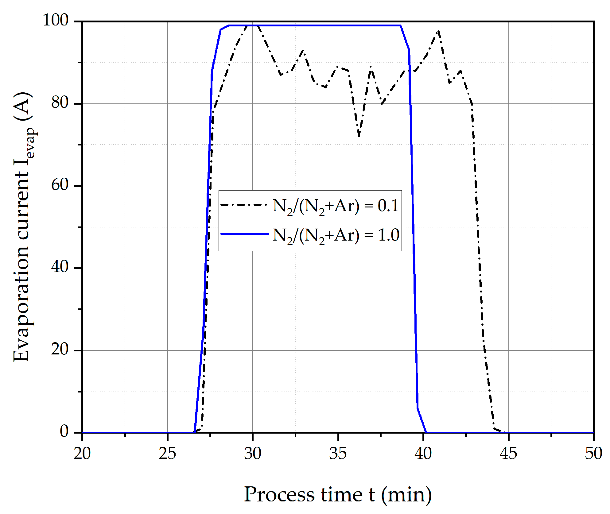
3.1. Deposition Rate

The deposition rate was determined using Equation (1) at a constant charge of approximately Q = 20 Ah and is shown in Figure 2 as a function of the nitrogen flow ratio RN2. A general trend shows that with increasing RN2 and higher working pressure, the deposition rate of the coating could be increased, which contrasts with the trends observed in the literature (see also Figure 1). As shown in [30], the evaporation rate of the evaporated material from the cathode decreases with increasing working pressure, so an increase in the deposition rate of the coating could be connected with differences in the coating density, which could not be verified in this work. For the working pressure of 5 Pa, a steeper rise of the deposition rate between N2/(N2 + Ar) 0.25 and 0.33 than for the working pressure of 2 Pa could be observed. For a working pressure of 2 Pa and N2/(N2 + Ar) < 0.25, the deposition rate significantly decreases due to instabilities of the plasma. This behavior at a working pressure of 2 Pa can be seen in the time–current curve in Figure 3. If only nitrogen is introduced into the chamber (RN2 = 1.0), the evaporation behavior of the cathode is determined by nitriding effects on the “contaminated” cathode surface, and type 1 focal spots are formed, as Anders stated [2]. The argon content is highest for the lowest nitrogen flow ratio RN2 = 0.1. In this case, the evaporation of the cathode became unstable and the evaporation current fluctuated considerably. This may be due to fluctuations in the cathode spots between type 1 and type 2, which do not occur at higher pressures. Furthermore, the observed instabilities in the time–current curve led to the subsequent triggering and ignition of new vacuum arcs. These delays resulted in an extended processing time.

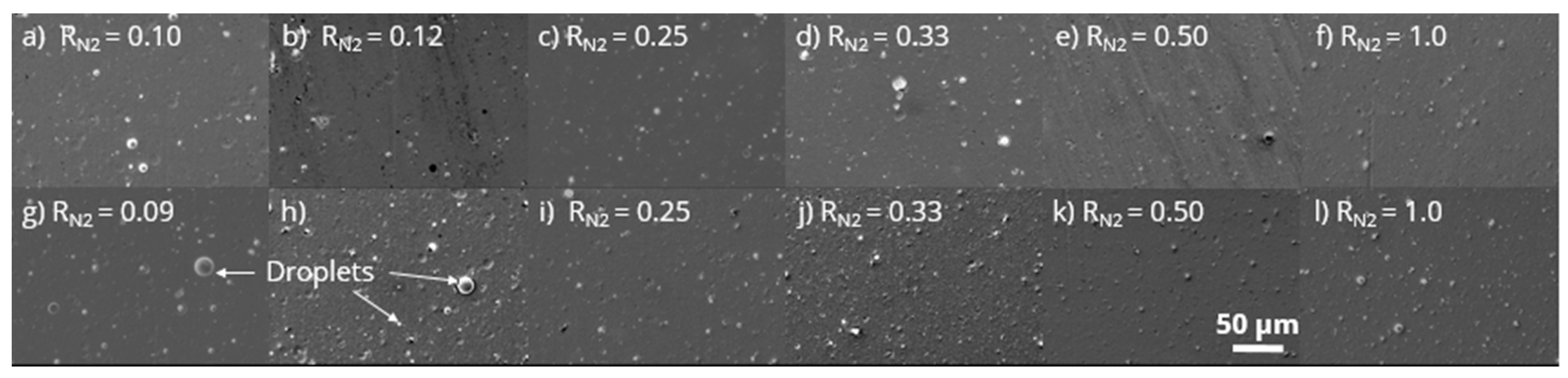
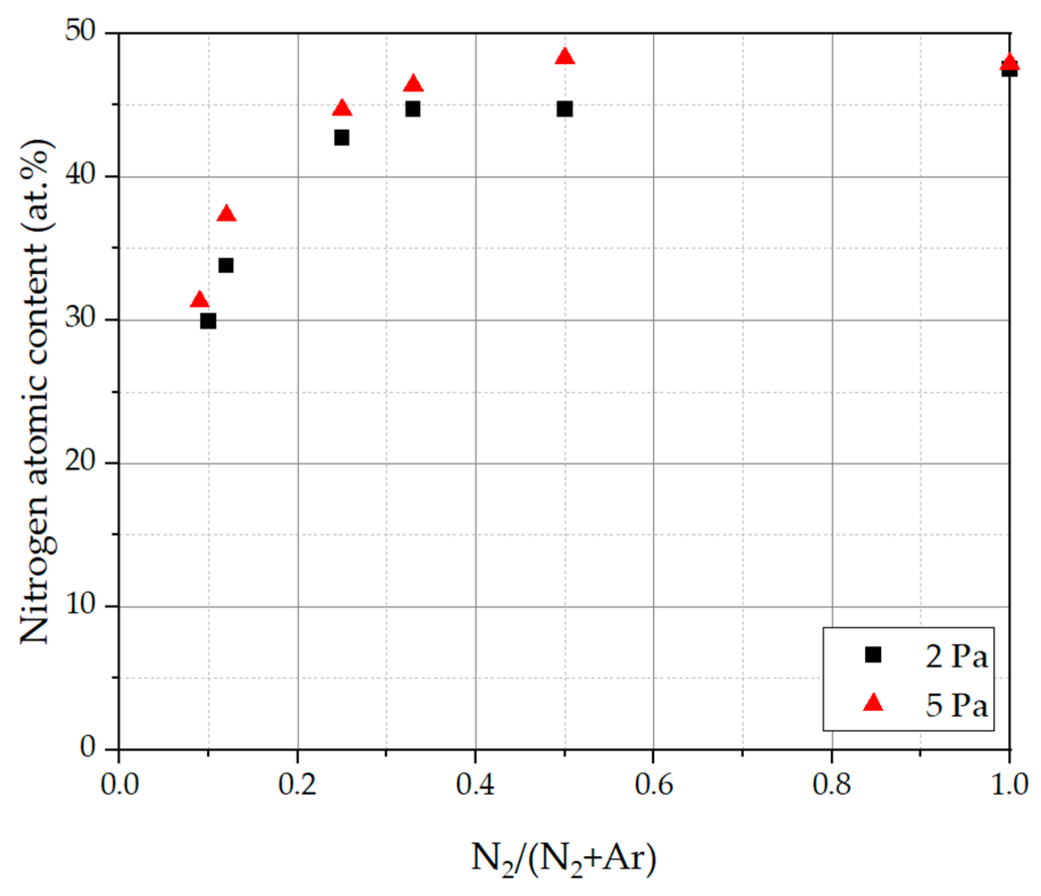
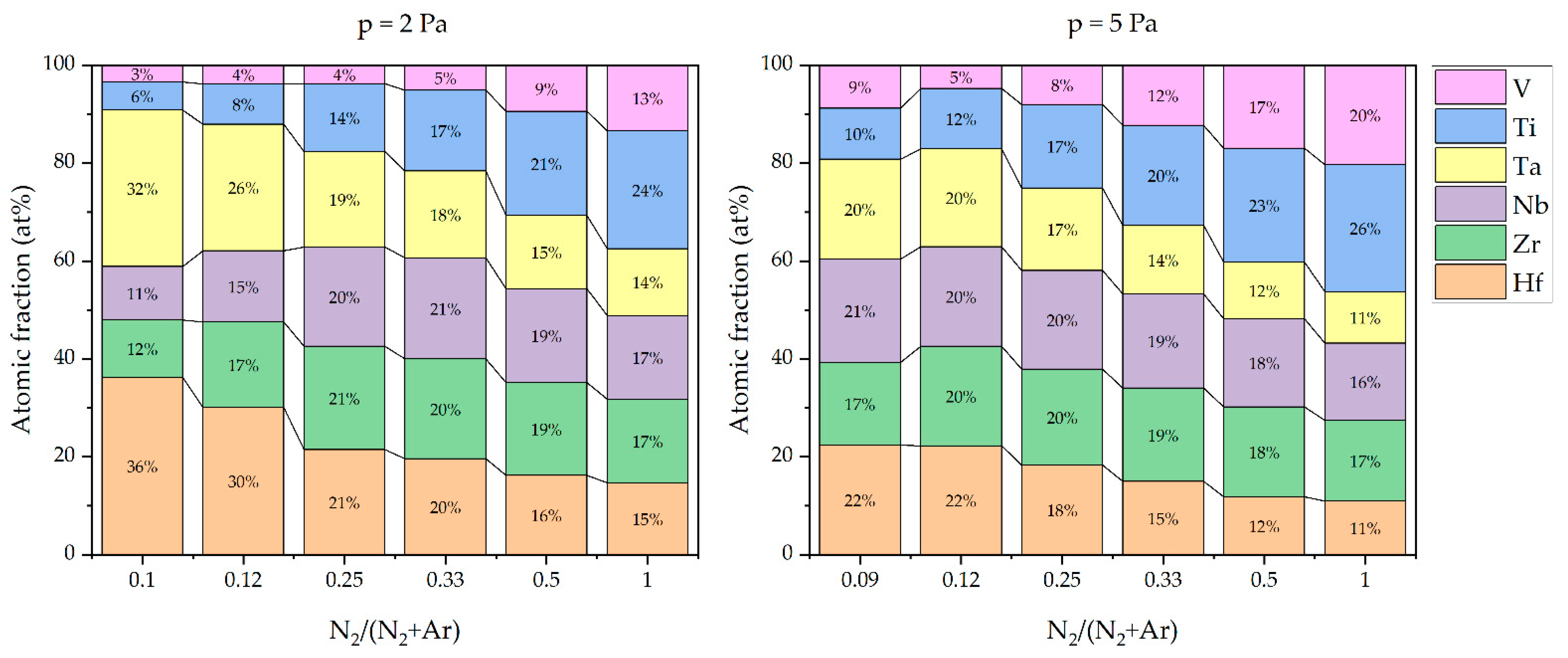
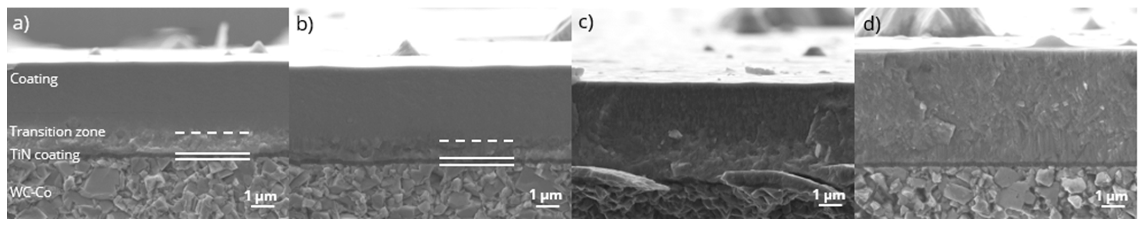
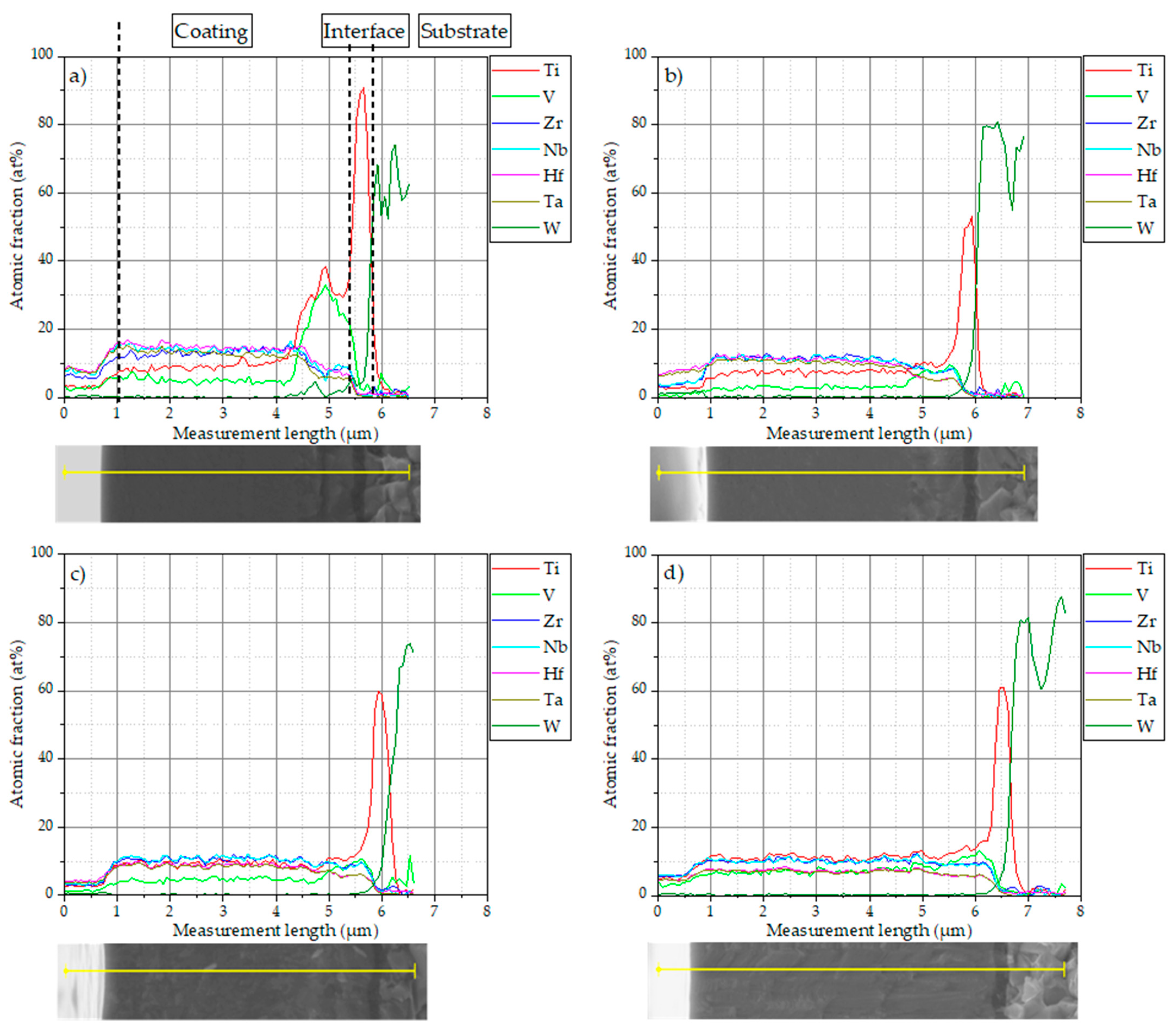
3.2. Coating Morphology and Composition

Figure 4 shows top-view SEM images of the surfaces of the coatings deposited at different working pressures and varying nitrogen flow ratios. For all coatings, macroparticles are visible, which likely stem from the CAE process. Between the working pressures of 2 Pa and 5 Pa, no major differences in the macroparticle structure can be observed. Increasing the nitrogen flow ratio could lead to a slight reduction in particle size.
The nitrogen content of each coating was determined at the coating surface using EDS and is presented in terms of the dependence of the N2/(N2 + Ar) ratio and the working pressure in Figure 5. As one can see, the nitrogen content increases significantly with an increasing nitrogen flow ratio from around 30 at% to almost 50 at% of nitrogen and slightly increases with an increasing working pressure from 2 Pa to 5 Pa. The content of the different metals is displayed in Figure 6. It is clear that for heavier metals the content decreases with the nitrogen flow ratio (Hf, Ta), whereas for lighter metals the content slightly increases (Ti, Zr, V). These effects may possibly be associated with different re-sputtering of heavy and light elements from the coating [19]. The Nb content increases up to a flow ratio of 0.25, remains stable to a flow ratio of 0.33 and then slightly decreases with a further increased flow ratio. If the working pressure is increased up to 5 Pa, the contents of Hf and Ta decrease, but not as much as at a working pressure of 2 Pa. The contents of Ti and V continue to increase with increased nitrogen flow. For Zr and Nb, the contents are comparatively constant with an increasing nitrogen flow ratio.
In Figure 7 cross sections of selected coatings are presented. In the case of low nitrogen flow ratio (RN2 = 0.09 and 0.12) the coatings have a glasslike homogenous structure. Near to the substrate/bond coat a transition zone (thickness in the range of 1–1.5 µm) is visible, the origin of which is still unclear, but which could likely be attributed to a change in the flow of nitrogen to a more argon-containing atmosphere. The formation of the transition zone is clearly visible in the EDS line scans shown in Figure 8a,b. Here the concentration of Ti and V are slightly increased. With increasing RN2, the formation of the transition zone could be suppressed, which is also indicated by a decrease in the Ti and V signal in Figure 8. By increasing the nitrogen flow ratio, the structures of the coatings become coarser.
The atomic fraction for the other elements exhibits a constant signal over the whole coating thickness. The atomic fraction below 1 µm did not result from coating composition as the electron beam is not directly on the cross section (see SEM images below the diagrams in Figure 8). For lower RN2 the scatter in the elemental composition is higher, whereas with an increasing nitrogen flow ratio the scatter between the atomic fractions is reduced.

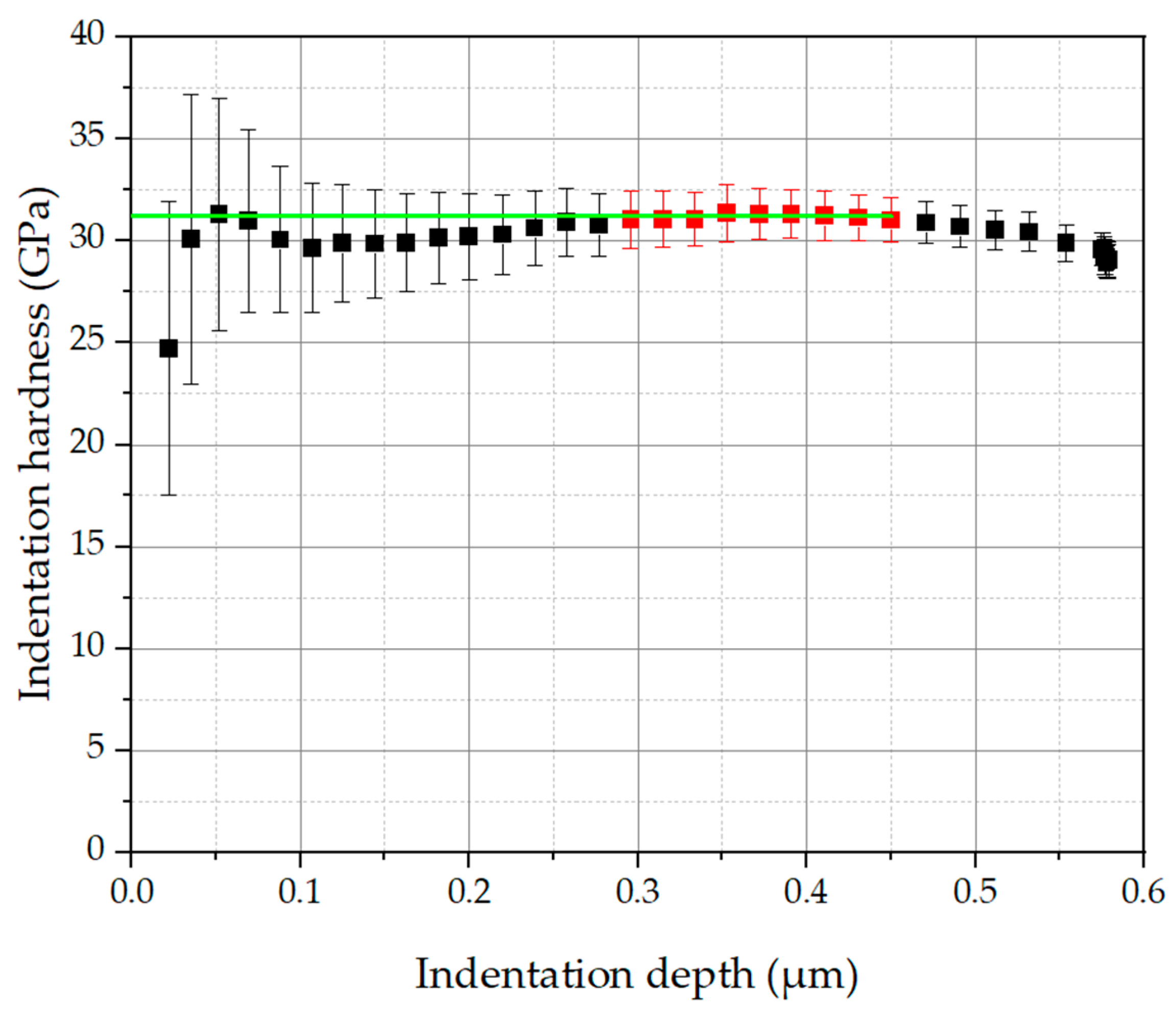
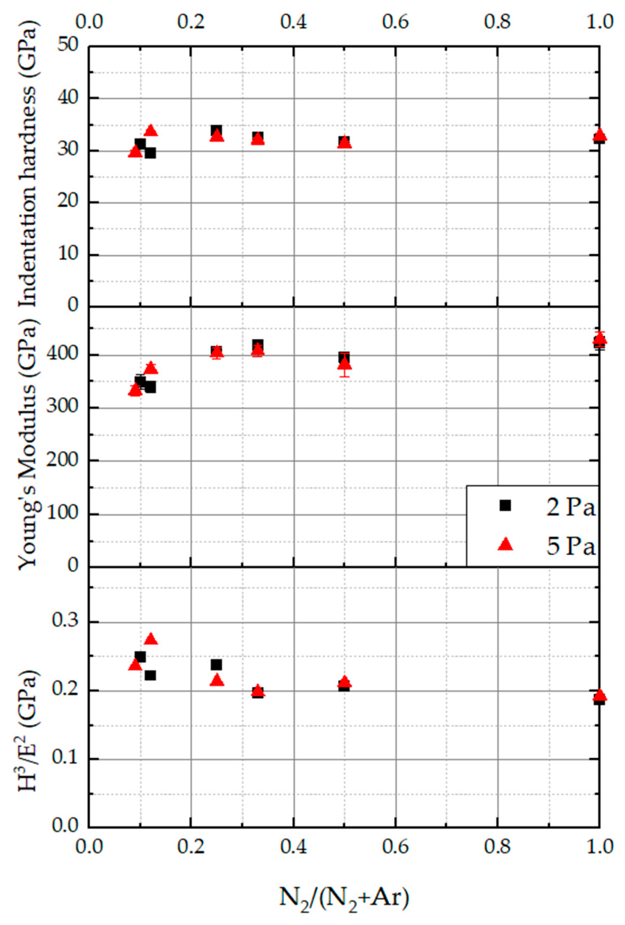
3.3. Mechanical Properties

The indentation hardness H, indentation modulus E and the H³/E² (often used as a measure of toughness) ratio in terms of the dependence of the nitrogen flow rate are shown in Figure 9. The error bars are indicated in the diagram and are in the range of ±0.5 GPa for the hardness values and ±20 GPa for Young’s modulus.
The variation of the working pressure from 2 to 5 Pa did not result in a significant change of the indentation hardness and Young’s modulus. If the nitrogen flow rate RN2 is increased, the hardness is slightly changed between 29 GPa (RN2 = 0.12) and 34 GPa (RN2 = 0.25) and Young’s modulus slightly increases from 330 GPa (RN2 = 0.09) up to 420 GPa (RN2 = 1.0), leading to a slight decrease in the H3/E2 ratio.

3.4. Structural Analysis

XRD data for the variation of the substrate bias voltage and working pressure variation is presented in Figure 10, respectively. The respective peak positions of TiN and WC-Co are marked in the graphs with solid and dashed lines. All coatings display a single-phase fcc (NaCl type) structure with more or less pronounced substrate peaks. The peak positions are comparable for both investigated working pressures and for the variation of the nitrogen flow ratios. A pronounced fcc structure could be obtained for high RN2. If the nitrogen flow ratio decreases, the (111) peaks probably shifted to lower angles, which could be masked by the substrate peaks and disappear for even smaller nitrogen flow ratios. The (200) and the (220) peaks have shifted to lower angles, lost intensity and become broader, indicating a smaller crystallite size, lattice constant and likely a loss in crystallinity. For (200) the full width at half maximum (FWHM200) is shown in Figure 11. One can see an increase in the FWHM with decreasing nitrogen flow ratio, indicating a smaller grain size in the coatings. For both working pressures, the FWHM are in the same range. The reason for the higher FWHM for RN2 = 0.5 at p = 5 Pa is still unclear.

4. Discussion

4.1. Deposition Rate

The deposition rates for CAE processes, presented in Figure 2, are significantly higher than those reported in the literature (see Figure 1). Furthermore, an opposite trend to the published coating rates with increasing RN2 can be seen. The reasons for this behavior could be the higher erosion rate of the cathode material in the gas atmosphere and/or the incorporation of droplets. However, this must be clarified by further investigations of the evaporation behavior of the cathode material and the particle structure. Magnetron sputtering processes are driven by the sputter yield of the single materials bombarded with Ar+ ions. Whereas especially magnetron sputtering processes exhibit pronounced target poisoning in gaseous atmospheres of nitrogen or oxygen, the deposition rates of the coatings decrease with an increased number of gaseous species leading to ceramic formation on the target surface, decreasing the sputter yield [9]. In CAE the surfaces of the cathodes also form ceramics, but it is assumed that this does not necessarily decrease the deposition rate. Normally the arc spot velocity in CAE processes with nitrogen atmosphere is increased, leading to a decrease in macroparticle diameters [2]. By increasing the working pressure in the chamber, the mean free path of the plasma species is decreased and so re-sputtering at the coating surface is suppressed, leading to a higher deposition rate. Xia et al. investigated the differences between MS and CAE deposition [15]. Here the deposition rate for CAE was 8.4 µm/h (140 nm/min) at a working pressure of 5 Pa whereas for DCMS the rate was just between 1.56 and 1.92 µm/h (26 and 32 nm/min) at a working pressure of 0.5 Pa. In this case, the differences in the deposition rates may be due to the different target–substrate distances (CAE: 25 cm; MS: 65 cm) and coating pressures (CAE: 5 Pa; MS: 0.5 Pa). For a better understanding of the underlying processes, it would also be beneficial to study the mass loss of the cathodes, as the deposition rate is dependent on, e.g., pressure and distance [1].
Kuczyk et al. [7] reported deposition rates for CAE coatings. Two systems at constant bias potential and varying working pressures between 0.5 and 5.0 Pa with RN2 = 1.0 were deposited, showing higher deposition rates between 29 and 35 µm/h (483 and 583 nm/min). The loss in deposition rate for 2 Pa and low RN2 in this study is likely caused by process instabilities during the arc ignition (see Figure 3). This behavior is still unclear and should be investigated further.

4.2. Nitrogen Content

By increasing the working pressure in the chamber and the nitrogen flow ratio RN2, the nitrogen content in the coatings is increased from nearly 30 at% to almost 50 at% (Figure 5). This behavior is comparable for CAE and MS coatings, reported by Hsueh et al. [11] and Xia et al. [15]. In particular, Xia et al. [15] investigated the difference between coatings deposited with MS and CAE, where the increase in the nitrogen content in the MS-deposited coatings is steeper with an increased nitrogen flow ratio than for CAE-deposited coatings. In this study, the gain in nitrogen content is even more pronounced compared with the work of Xia et al. [15]. They found that with increasing nitrogen content in the coatings, more nitrogen is dissolved into the crystal lattice. This led to lattice distortions and the formation of smaller grains, indicated by broader reflexes in the diffraction pattern [15]. Those findings are in contrast to the results presented here.
Peak broadening may also be caused by residual stress resulting from the incorporation of nitrogen, but the influence of the stress state of the deposited coatings is still unclear and needs to be investigated further.

4.3. Mechanical Properties

The analyzed mechanical properties of the (HfNbTaTiVZr)N coating did not exhibit a significant change with the working pressure from 2 Pa to 5 Pa. This behavior could be shown in a previous work [7] for RN2 = 1.0. As the working pressure increases, the grain size and therefore the indentation hardness as well as the Young’s modulus of the coatings remained almost unchanged. A further finding was a quite stable metal–nitrogen ratio over the working pressure, indicating an almost pressure-independent deposition [7]. In the present study, the nitrogen flow ratio RN2 also varied, which led to a change in the nitrogen content in the layer but did not change the hardness and Young’s modulus significantly. In Figure 12 a comparison between the hardness and nitrogen atomic content from several investigations on similar coating systems [(CrHfNbTaTiVZr)N [9]; (TiNbZrTa)N [13]; (HfTaTiVZr)N [19] and (TiZrNbTaFe)N [21]] and this work is displayed. As can be seen, none of the similar material systems show a comparable progression of hardness over the nitrogen content. Kirnbauer et al. [19] analyzed (HfTaTiVZr)N and found similar hardness values compared with the results presented in this study. The variation of the nitrogen flow rate did not affect the nitrogen and the metal content in the coating, and thus the hardness only slightly differed. For RN2 < 0.5 they found a single phase fcc structure and a globular- to columnar-like microstructure. For RN2 ≥ 0.5 an additional crystal phase is formed, which initially inhibits grain growth and thus leads to a maximum hardness due to grain refinement. The other systems investigated by Tsai et al. —(CrHfNbTaTiVZr)N [9]; Shu et al.—(TiNbZrTa)N [13] and Bachani et al.—(TiZrNbTaFe)N [21] show either a steep drop in hardness or a comparatively short hardness plateau. Tsai et al. [9] explained the hardness drop with an increase in the grain size of the fcc phase with decreasing RN2 and the formation of an amorphous phase. Shu et al. [13] observed a bcc crystal phase in the absence of nitrogen and a fcc crystal phase for increasing nitrogen content in the coatings. The reason for the increasing hardness was the increasing nitrogen content accompanied with a grain refinement. Bachani et al. [21] attributed the increase in hardness with increasing nitrogen content to the formation of solid solutions and the transition from an amorphous to a crystalline phase, which was also reported in several studies [4,18,21,23]. The following drop in hardness at nitrogen contents above 36.8 at% was caused by target poisoning or the inverse Hall–Petch relationship.
However, in CAE-deposited (MoNbTaVW)N coatings, investigated by Xia et al. [15], a change from the bcc to the fcc phase could be detected. They also obtained a wide range of nearly constant hardness (28–30 GPa) with increasing nitrogen content (4 at%–35 at%).
The almost constant hardness with increasing nitrogen content in the present work could be the result of competing effects. According to the concept of solid solution hardening, the hardness should increase with higher nitrogen content. However, due to the change in coating structure with decreasing grain size (see Figure 11), the layer hardness remains high, probably due to grain refinement. The phase diagram of Ti-N [37] shows a broad range of existence for cubic TiN with a minimum at 28 at% for nitrogen at a temperature of 2350 °C, whereas the minimum nitrogen content reaches values of more than 40 at% at temperatures below 350 °C.
A fundamental difference between CAE and sputter processes is the different ionization in the deposition plasma. CAE plasmas are typically fully ionized with significantly higher ion energies, whereas sputtering atmospheres have ionized fractions of about 5%–10% and lower ion energies [1]. This leads to a broader process window for a stable deposition process in CAE compared to sputter processes.

5. Conclusions

HEN coatings in the system (HfNbTaTiVZr)N were produced by means of DC cathodic vacuum arc deposition from powder metallurgically produced targets. The main findings are:
  • In contrast to magnetron sputtering processes (Figure 1), the deposition rate increases with an increasing N2/(N2 + Ar) ratio, since in DC cathodic vacuum arc deposition target poisoning does not hinder the evaporation of the cathode material.
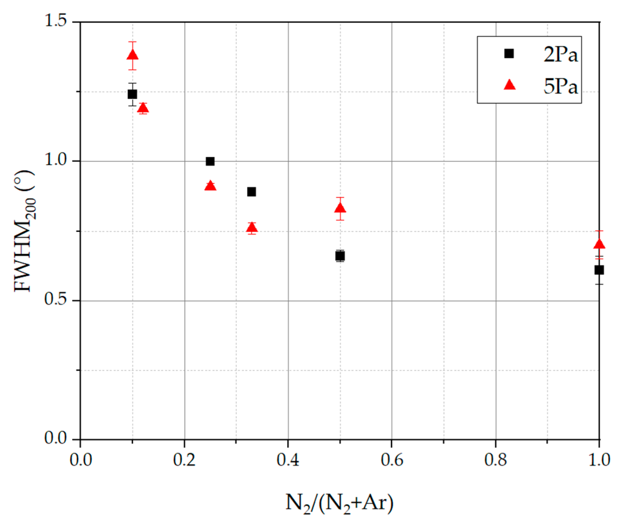
  • An increasing N2/(N2 + Ar) ratio led to an increase in the nitrogen atomic content in the deposited coatings, which could be observed in several studies in the literature. If the N2/(N2 + Ar) ratio and therefore the nitrogen content in the coatings is decreased, a broadening of XRD reflexes could be obtained, leading to a fine-grained and homogeneous microstructure. As the nitrogen content increases, the microstructure becomes coarse and columnar. Despite the change in N2/(N2 + Ar) ratio and nitrogen content, the analyzed coatings showed a single phase fcc structure. This is in contrast to other HEN coating systems in the literature, which could exhibit differing crystal phases or even amorphous phases. For the presented CAE processes with their high deposition rate and energy input, it is probably difficult to reach the amorphous region. This underlines the stability of the CAE process preparing crystalline coatings over a broad variety of nitrogen flow ratios and thus with changing nitrogen contents.
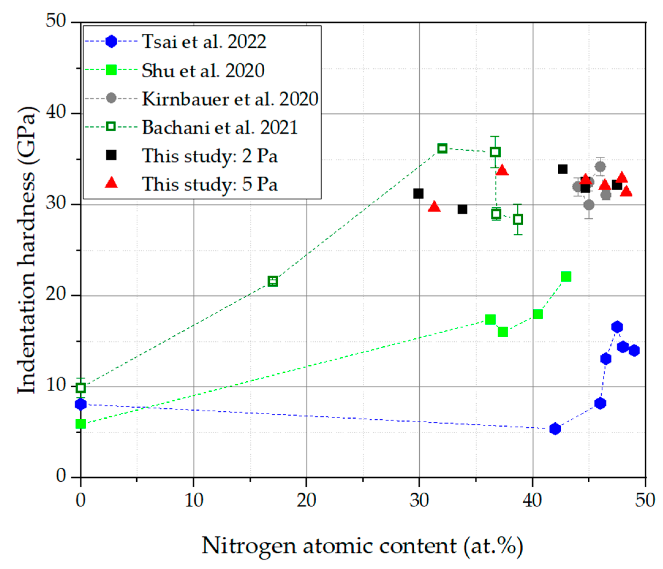
  • Although the nitrogen content in the coatings is significantly changed with an increasing N2/(N2 + Ar) ratio, the indentation hardness and the Young’s modulus of the coatings are only slightly affected. This effect could be due to competing effects: solid solution hardening with increasing nitrogen content on the one hand and grain refinement with decreasing nitrogen content on the other hand.
  • A transition zone is obtained in the case of low N2/(N2 + Ar) with a higher concentration of Ti and V, which has not been fully understood until now, but can likely be attributed to a change in the gas atmosphere during deposition of the TiN bond coating and the HEN coating.

Author Contributions

Conceptualization, T.K. and M.K.; methodology, T.K. and M.K.; validation, T.K., M.K. and M.L.; formal analysis, T.K. and M.K.; investigation, T.K., M.K. and M.L.; resources, M.L.; data curation, T.K., M.K. and M.L.; writing—original draft preparation, T.K.; writing—review and editing, T.K., M.K. and O.Z.; visualization, T.K., M.K. and M.L.; supervision, O.Z. and C.L.; project administration, O.Z.; funding acquisition, C.L. All authors have read and agreed to the published version of the manuscript.

Funding

This research was funded by the German Research Foundation (DFG), grant number LE 1373/69-1.

Institutional Review Board Statement

Not applicable.

Informed Consent Statement

Not applicable.

Data Availability Statement

Data available on request due to restrictions.

Acknowledgments

The authors would like to thank their colleagues and students of the Group of PVD coatings and the Group of Materials and Failure Analysis at Fraunhofer IWS and their colleagues at the Institute of Materials Science at TU Dresden.

Conflicts of Interest

The authors declare no conflicts of interest.

Appendix A

Exemplary EDS mappings are shown for the SEM surface images of RN2 = 0.1 and RN2 = 1.0 for a working pressure of p = 2 Pa presented in Figure 4a,f. For every element, a single image is shown, presenting a homogeneous distribution of the elements in the coatings. The positions of the droplets are visible for a higher intensity of single elements.
Figure A1. Exemplary EDS mapping for (HfNbTaTiVTiZr)N, deposited at p = 2 Pa with nitrogen flow ratio RN2 = 0.1 (first and second row) and RN2 = 1.0 (third and fourth row).
Coatings 14 00398 g0a1
Figure A2 shows the indentation over depth behavior of a (HfNbTaTiVZr)N coating, measured with the methode given in the Materials and Methods section. From the hardness plateau (red rectangles), the hardness of the coating was determined and the corresponding hardness value is represented by the green line. The local peak in the indentation depth < 0.1 µm is caused by the surface roughness, while the decreasing hardness at depths > 0.5 µm is due to the influence of the substrate material. This procedure was also used for carbon coatings deposited with PVD [38].
Figure A2. Indentation hardness over indentation depth: the coating hardness is determined from the hardness plateau (red rectangle and green line) according to Lorenz et al. [34].
Coatings 14 00398 g0a2

References

  1. Bach, F.-W.; Möhwald, K.; Laarmann, A.; Wenz, T. Modern Surface Technology; Wiley-VCH: Weinheim, Germany, 2006; ISBN 978-3-527-31532-1. [Google Scholar]
  2. Anders, A. Cathodic Arcs; Springer: New York, NY, USA, 2008; ISBN 978-0-387-79107-4. [Google Scholar]
  3. Novikov, V.; Stepanov, N.; Zherebtsov, S.; Salishchev, G. Structure and Properties of High-Entropy Nitride Coatings. Metals 2022, 12, 847. [Google Scholar] [CrossRef]
  4. Padamata, S.K.; Yasinskiy, A.; Yanov, V.; Saevarsdottir, G. Magnetron Sputtering High-Entropy Alloy Coatings: A Mini-Review. Metals 2022, 12, 319. [Google Scholar] [CrossRef]
  5. Gao, M.C.; Yeh, J.-W.; Liaw, P.K.; Zhang, Y. High-Entropy Alloys; Springer International Publishing: Cham, Switzerlands, 2016; ISBN 978-3-319-27011-1. [Google Scholar]
  6. Murty, B.S.; Yeh, J.W.; Ranganathan, S. High-Entropy Alloys; Elsevier: Amsterdam, The Netherlands, 2014; ISBN 978-0-12-800251-3. [Google Scholar]
  7. Kuczyk, M.; Krülle, T.; Zawischa, M.; Kaspar, J.; Zimmer, O.; Leonhardt, M.; Leyens, C.; Zimmermann, M. Microstructure and mechanical properties of high entropy alloy nitride coatings deposited via direct current cathodic vacuum arc deposition. Surf. Coat. Technol. 2022, 448, 128916. [Google Scholar] [CrossRef]
  8. Kim, Y.S.; Park, H.J.; Lim, K.S.; Hong, S.H.; Kim, K.B. Structural and Mechanical Properties of AlCoCrNi High Entropy Nitride Films: Influence of Process Pressure. Coatings 2020, 10, 10. [Google Scholar] [CrossRef]
  9. Tsai, D.-C.; Chen, E.-C.; Chang, Z.-C.; Shieu, F.-S. Effect of Nitrogen Partial Pressure on the Structural, Mechanical, and Electrical Properties of (CrHfNbTaTiVZr)N Coatings Deposited by Reactive Magnetron Sputtering. Coatings 2022, 12, 437. [Google Scholar] [CrossRef]
  10. Tsai, D.-C.; Huang, Y.-L.; Lin, S.-R.; Liang, S.-C.; Shieu, F.-S. Effect of nitrogen flow ratios on the structure and mechanical properties of (TiVCrZrY)N coatings prepared by reactive magnetron sputtering. Appl. Surf. Sci. 2010, 257, 1361–1367. [Google Scholar] [CrossRef]
  11. Hsueh, H.-T.; Shen, W.-J.; Tsai, M.-H.; Yeh, J.-W. Effect of nitrogen content and substrate bias on mechanical and corrosion properties of high-entropy films (AlCrSiTiZr)100−xNx. Surf. Coat. Technol. 2012, 206, 4106–4112. [Google Scholar] [CrossRef]
  12. Stasiak, T.; Soucek, P.; Bursikova, V.; Vasina, P. Magnetron Sputtering Deposition of High Eentropy Nitrides from Chromium-Hafnium-Molybdenum-Tantalum-Wolfram System. In Proceedings of the NANOCON 2021, Brno, Czech Republic, 20–22 October 2021; Tanger Ltd.: Ostrava, Czech Republic, 2021; pp. 98–103. [Google Scholar]
  13. Shu, R.; Paschalidou, E.-M.; Rao, S.G.; Bakhit, B.; Boyd, R.; Moro, M.V.; Primetzhofer, D.; Greczynski, G.; Nyholm, L.; Le Febvrier, A.; et al. Effect of nitrogen content on microstructure and corrosion resistance of sputter-deposited multicomponent (TiNbZrTa)Nx films. Surf. Coat. Technol. 2020, 404, 126485. [Google Scholar] [CrossRef]
  14. Lee, J.-W.; Lou, B.-S.; Hung, T.-Y.; Lee, C.-H.; Chen, H.-Y. Effects of nitrogen contents on the phase evolution, microstructure and mechanical properties of high entropy alloy coatings. In Proceedings of the 18th International Conference on Plasma Surface Engineering, Erfurt, Germany, 12–15 September 2022. [Google Scholar]
  15. Xia, A.; Dedoncker, R.; Glushko, O.; Cordill, M.J.; Depla, D.; Franz, R. Influence of the nitrogen content on the structure and properties of MoNbTaVW high entropy alloy thin films. J. Alloys Compd. 2021, 850, 156740. [Google Scholar] [CrossRef]
  16. Li, H.; Jiang, N.; Li, J.; Huang, J.; Kong, J.; Xiong, D. Hard and tough (NbTaMoW)Nx high entropy nitride films with sub-stoichiometric nitrogen. J. Alloys Compd. 2021, 889, 161713. [Google Scholar] [CrossRef]
  17. Lai, C.-H.; Lin, S.-J.; Yeh, J.-W.; Chang, S.-Y. Preparation and characterization of AlCrTaTiZr multi-element nitride coatings. Surf. Coat. Technol. 2006, 201, 3275–3280. [Google Scholar] [CrossRef]
  18. Cui, P.; Li, W.; Liu, P.; Zhang, K.; Ma, F.; Chen, X.; Feng, R.; Liaw, P.K. Effects of nitrogen content on microstructures and mechanical properties of (AlCrTiZrHf)N high-entropy alloy nitride films. J. Alloys Compd. 2020, 834, 155063. [Google Scholar] [CrossRef]
  19. Kirnbauer, A.; Kretschmer, A.; Koller, C.M.; Wojcik, T.; Paneta, V.; Hans, M.; Schneider, J.M.; Polcik, P.; Mayrhofer, P.H. Mechanical properties and thermal stability of reactively sputtered multi-principal-metal Hf-Ta-Ti-V-Zr nitrides. Surf. Coat. Technol. 2020, 389, 125674. [Google Scholar] [CrossRef]
  20. Lin, Y.-C.; Hsu, S.-Y.; Lai, Y.-T.; Kuo, P.-H.; Tsai, S.-Y.; Duh, J.-G. Effect of the N2/(Ar+N2) ratio on mechanical properties of high entropy nitride (Cr0.35Al0.25Nb0.12Si0.08V0.20)Nx films. Mater. Chem. Phys. 2021, 274, 125195. [Google Scholar] [CrossRef]
  21. Bachani, S.K.; Wang, C.-J.; Lou, B.-S.; Chang, L.-C.; Lee, J.-W. Fabrication of TiZrNbTaFeN high-entropy alloys coatings by HiPIMS: Effect of nitrogen flow rate on the microstructural development, mechanical and tribological performance, electrical properties and corrosion characteristics. J. Alloys Compd. 2021, 873, 159605. [Google Scholar] [CrossRef]
  22. Tsai, M.-H.; Lai, C.-H.; Yeh, J.-W.; Gan, J.-Y. Effects of nitrogen flow ratio on the structure and properties of reactively sputtered (AlMoNbSiTaTiVZr)N x coatings. J. Phys. D Appl. Phys. 2008, 41, 235402. [Google Scholar] [CrossRef]
  23. Huang, P.-K.; Yeh, J.-W. Effects of nitrogen content on structure and mechanical properties of multi-element (AlCrNbSiTiV)N coating. Surf. Coat. Technol. 2009, 203, 1891–1896. [Google Scholar] [CrossRef]
  24. Zhang, C.; Lu, X.; Wang, C.; Sui, X.; Wang, Y.; Zhou, H.; Hao, J. Tailoring the microstructure, mechanical and tribocorrosion performance of (CrNbTiAlV)N high-entropy nitride films by controlling nitrogen flow. J. Mater. Sci. Technol. 2022, 107, 172–182. [Google Scholar] [CrossRef]
  25. Bunshah, R.F. (Ed.) Handbook of Hard Coatings: Deposition Technologies, Properties and Applications; Noyes Publications: Norwich, NY, USA; William Andrew Publishing: Park Ridge, NJ, USA, 2001; ISBN 0815514387. [Google Scholar]
  26. Mattox, D.M. Particle bombardment effects on thin-film deposition: A review. J. Vac. Sci. Technol. A Vac. Surf. Film. 1989, 7, 1105–1114. [Google Scholar] [CrossRef]
  27. Rother, B.; Vetter, J. Plasmabeschichtungsverfahren und Hartstoffschichten, 1st ed.; Dt. Verl. für Grundstoffindustrie: Leipzig, Germany, 1992; ISBN 3342006498. [Google Scholar]
  28. Zimmer, O. Vacuum arc deposition by using a Venetian blind particle filter. Surf. Coat. Technol. 2005, 200, 440–443. [Google Scholar] [CrossRef]
  29. Siemroth, P.; Schülke, T. Copper metallization in microelectronics using filtered vacuum arc deposition—principles and technological development. Surf. Coat. Technol. 2000, 133-134, 106–113. [Google Scholar] [CrossRef]
  30. Krülle, T.; Leonhardt, M.; Kuczyk, M.; Srocke, S.; Zimmer, O.; Leyens, C. Untersuchung des Verdampfungsprozesses und der Schichtabscheidung von nitridischen Hochentropielegierungen mittels PVD-Verdampfung. In Jahrbuch Oberflächentechnik 2023; Sörgel, T., Ed.; Eugen, G. Leuze Verlag: Bad Saulgau, Germany, 2023; ISBN 978-3-87480-385-4. [Google Scholar]
  31. DIN EN ISO 26423:2016-11; Hochleistungskeramik—Bestimmung der Schichtdicke mit dem Kalottenschleifverfahren. Beuth Verlag GmbH: Berlin, Germany, 2016.
  32. DIN EN ISO 14577-1:2015-11; Metallische Werkstoffe—Instrumentierte Eindringprüfung zur Bestimmung der Härte und anderer Werkstoffparameter—Teil 1: Prüfverfahren. Beuth Verlag GmbH: Berlin, Germany, 2015.
  33. Präßler, F.; Grimm, W.; Chudoba, T. Properties of ta-C Films for Tools and Machinery Parts. Plasma Process. Polym. 2009, 6, S468–S472. [Google Scholar] [CrossRef]
  34. Lorenz, L.; Chudoba, T.; Makowski, S.; Zawischa, M.; Schaller, F.; Weihnacht, V. Indentation modulus extrapolation and thickness estimation of ta-C coatings from nanoindentation. J. Mater. Sci. 2021, 19, 18740–18748. [Google Scholar] [CrossRef]
  35. ZwickRoell GmbH Co. KG. Available online: https://www.zwickroell.com/industries/academia/nanoindentation/ (accessed on 16 March 2024).
  36. Wang, Z.; Wang, C.; Zhao, Y.-L.; Huang, T.-H.; Li, C.-L.; Kai, J.-J.; Liu, C.-T.; Hsueh, C.-H. Growth, microstructure and mechanical properties of CoCrFeMnNi high entropy alloy films. Vacuum 2020, 179, 109553. [Google Scholar] [CrossRef]
  37. Wriedt, H.A.; Murray, J.L. The N-Ti (Nitrogen-Titanium) system. Bull. Alloy Phase Diag. 1987, 8, 378–388. [Google Scholar] [CrossRef]
  38. Zawischa, M.; Weihnacht, V.; Kaspar, J.; Zimmermann, M. Effect of doping elements to hydrogen-free amorphous carbon coatings on structure and mechanical properties with special focus on crack resistance. Mater. Sci. Eng. A 2022, 857, 144086. [Google Scholar] [CrossRef]
Figure 1. Deposition rate in terms of the dependence of the nitrogen flow ratio RN2, derived from several references cited in the legend [8,9,10,13,16,17,20,21,22,23,24]. The corresponding coating system is given in Table 1.
Coatings 14 00398 g001
Figure 2. Deposition rate in terms of the dependence of the N2/(N2 + Ar) ratio and the working pressure.
Coatings 14 00398 g002
Figure 3. Time–current curve during the evaporation process step on the HfNbTaTiVZr cathode in terms of the dependence of the N2/(N2 + Ar) ratio 0.1 and 1.0 at a working pressure of p = 2 Pa.
Coatings 14 00398 g003
Figure 4. Surfaces for (HfNbTaTiVZr)N coatings, deposited at working pressures of p = 2 Pa (upper row: af) and p = 5 Pa (bottom row: gl) and varying nitrogen flow ratios RN2. Exemplary EDS mappings can be found in the Appendix A in Figure A1.
Coatings 14 00398 g004
Figure 5. Nitrogen atomic content in terms of the dependence of the N2/(N2 + Ar) ratio and the working pressure.
Coatings 14 00398 g005
Figure 6. Metal content in terms of the dependence of the nitrogen flow ratio and a working pressure p = 2 Pa (left) and p = 5 Pa (right).
Coatings 14 00398 g006
Figure 7. Cross sections of (HfNbTaTiVZr)N coatings deposited at p = 5 Pa with different nitrogen flow ratios: (a) 0.09; (b) 0.12; (c) 0.25 and (d) 0.33.
Coatings 14 00398 g007
Figure 8. EDS line scans of (HfNbTaTiVZr)N coatings (see cross sections in Figure 7) deposited at p = 5 Pa with different nitrogen flow ratios: (a) 0.09; (b) 0.12; (c) 0.25 and (d) 0.33. The line scan measurement started close (x = 0) to the coating surface (x ≈ 1) and stopped just below the interface within the substrate material (x ≈ 7–8 µm).
Coatings 14 00398 g008
Figure 9. Indentation hardness, indentation Young’s modulus and H3/E2 ratio in terms of the dependence of the N2/(N2 + Ar) ratio for working pressure.
Coatings 14 00398 g009
Figure 10. XRD analysis in terms of the dependence of the nitrogen flow rate for different working pressures: (a) p = 2 Pa and (b) p = 5 Pa. The peak positions of the WC-Co substrate and the fcc phase (TiN) are marked by dashed and solid lines, respectively.
Coatings 14 00398 g010
Figure 11. Full width at half maximum (FWHM) of the (200) peak as a function of the nitrogen flow ratio N2/(N2 + Ar) at working pressures of 2 Pa and 5 Pa.
Coatings 14 00398 g011
Figure 12. Comparison between the indentation hardness values of this work with studies on similar material systems: Tsai et al.—(CrHfNbTaTiVZr)N [9]; Shu et al.—(TiNbZrTa)N [13]; Kirnbauer et al.—(HfTaTiVZr)N [19]; and Bachani et al.—(TiZrNbTaFe)N [21].
Coatings 14 00398 g012
Table 1. Literature overview of selected HEN coating systems; CAE—cathodic arc deposition; HiPIMS—High-Power Impulse Magnetron Sputtering; MS—reactive magnetron sputtering; RF UMS—radio-frequency unbalanced magnetron sputtering; DCMS—direct current magnetron sputtering; PM—powder metallurgical; VA—vacuum arc melted; CIP—cold isostatically pressed; nc—not communicated.
HEAN SystemDeposition ProcessUtilized TargetsStudied Process InfluencesDescribed Maximum Indentation Hardness at Pressure and RN2Reference
(AlCoCrNi)NDCMSPM targetInfluence of process pressure on structure and mechanical propertiesHmax = 8.2 GPa at p = 1.33 Pa and RN2 = 0.25[8]
(CrHfNbTaTiVZr)NDCMSEquimolar VA targetEffect of N2 partial pressure on structural, mechanical and electrical propertiesHmax = 16.6 GPa at p = nc and RN2 = 0.6[9]
(TiVCrZrY)NDCMSEquimolar PM targetEffect of N2 flow ratio on structure and mechanical propertiesHmax = 17.5 GPa at p = nc and RN2 = 1.0[10]
(AlCrSiTiZr)NMSEquimolar VA targetEffect of N2 content and substrate bias on mech. and corrosion propertiesHmax = 17 GPa at p = nc and RN2 = 0.05[11]
(CrHfMoTaW)NMSCr and segmented Mo/Hf and Ta/W targetsInfluence of N2 flow and deposition temperature on microstructure and mechanical propertiesHmax(RT) = 21.9 GPa at p = nc and RN2 = nc; Hmax(700 °C) = 26.6 GPa at p = nc and RN2 = nc[12]
(TiNbZrTa)NMSSegmented Nb/Zr and Ti/Ta targetsEffect of N2 content on microstructureHmax = 22.1 GPa at p = nc and RN2 = 0.25 and 43 at% nitrogen atomic content (coating)[13]
(VNbMoTaWTiAl)NHiPIMSPM targetEffect of N2 flow rate on microstructure, mechanical and tribological performanceHmax = 22.9 GPa at p = nc and RN2 = nc and 13.1 at% nitrogen atomic content (coating)[14]
(VNbMoTaW)NHiPIMSPM targetHmax = 26.8 GPa at p = nc and RN2 = nc and 22 at% nitrogen atomic content (coating)
(MoNbTaVW)NCAE and DCMSEquimolar PM target (CAE) and equimolar CIP target (DCMS)Influence of N2 content on structure and mechanical propertiesHmax(CAE) = 30 GPa at p = nc and RN2 = 0.25 and 20 at% nitrogen atomic content (coating); Hmax(DCMS) = 32 GPa at p = nc and RN2 = 0.05; 25 at% nitrogen atomic content (coating)[15]
(NbTaMoW)NDCMSEquimolar PM target Hmax = 30.8 GPa at p = nc and RN2 = 0.1[16]
(AlCrTaTiZr)NRF MSEquimolar VA targetInfluence of N2 flow ratio on chemical composition, microstructure and mechanical propertiesHmax = 32.0 GPa at p = nc and RN2 = 0.14[17]
(AlCrTiZrHf)NMSEquimolar targetEffect of N2 content on microstructure and mechanical propertiesHmax = 33.1 GPa at p = nc and RN2 = 0.56[18]
(HfTaTiVZr)NMSEquimolar PM targetEffect of N2 flow rate on microstructure and mechanical propertiesHmax = 34.0 GPa at p = nc and RN2 = 0.5[19]
(CrAlNbSiV)NRF MSCr0.35Al0.25Nb0.12Si0.08V0.20 targetEffect of N2 flow ratio on crystal structure, chemical composition, deposition rate, residual stress and mechanical propertiesHmax = 35.0 GPa at p = nc and RN2 = 0.33[20]
(TiZrNbTaFe)NHiPIMSEquimolar targetEffect of N2 flow rate on microstructure, mechanical and tribological performanceHmax = 36.2 GPa at p = nc and RN2 = 0.1 and 32.0 at% at% nitrogen atomic content (coating)[14,21]
(AlMoNbSiTaTiVZr)NMSEquimolar targetEffect of N2 flow ratio on structure and propertiesHmax = 37.0 GPa at p = nc and RN2 = 0.5[22]
(AlCrNbSiTiV)NRF UMSEquimolar VA targetEffects of N2 content on structure and mechanical propertiesHmax = 41 GPa at p = nc and RN2 = 0.2–0.3[23]
(CrNbTiAlV)NMSCr and CrNbTiAlV targetsEffect of N2 flow on microstructure and tribocorrosionHmax = 49.95 GPa at p = nc and RN2 = nc and 35.7 at% nitrogen atomic content (coating)[24]
Table 2. Target composition.
Target ComponentsDetermined Target Composition (at%)
HfNbTaTiVZr17.5:17.5:16.8:16.3:15.8:16.0
Table 3. Process parameters for HEN coating.
Process ParameterValue Setting
Working pressure p (Pa)2; 5
N2/(N2 +Ar) flow ratio0.1; 0.25; 0.33; 0.5; 0.66; 1.0
Bias voltage Ubias (V)−200
Evaporation current Ievap (A)100
Electrical charge Q (Ah)20
Deposition time (h)
Distance target-sample s (mm)
0.2
170
Sample movementFixed in front of the target
Substrate temperature Tsubs (°C)≤550 °C
Table 4. Compilation of utilized analyzing techniques.
Characterization MethodDeviceAim of Analysis
Calo testKSG110 (Inovap HEF Group, Andrézieux-Bouthéon, France)Coating thickness and deposition rate
Scanning Electron Microscopy (SEM)JSM-7800-F (JEOL, Tokyo, Japan)Structural analysis on as-deposited surfaces, fracture surfaces and cross sections
Energy Dispersive X Ray Spectrocopy (EDS)X-max 80 (Oxford Instruments, Abingdon, UK)Coating composition
X Ray Diffraction (XRD)D5005 (Siemens, Munich, Germany)Structural analysis
Instrumented NanoindentationZHN-1 (ZwickRoell, Ulm, Germany)Indentation hardness and Young’s modulus
Disclaimer/Publisher’s Note: The statements, opinions and data contained in all publications are solely those of the individual author(s) and contributor(s) and not of MDPI and/or the editor(s). MDPI and/or the editor(s) disclaim responsibility for any injury to people or property resulting from any ideas, methods, instructions or products referred to in the content.

