
Effects of Heat Treatment and Erosion Particle Size on Erosion Resistance of a Hypereutectic High-Chromium Cast Iron


Abstract
1. Introduction
2. Materials and Methods
3. Results and Discussion
4. Conclusions
- -
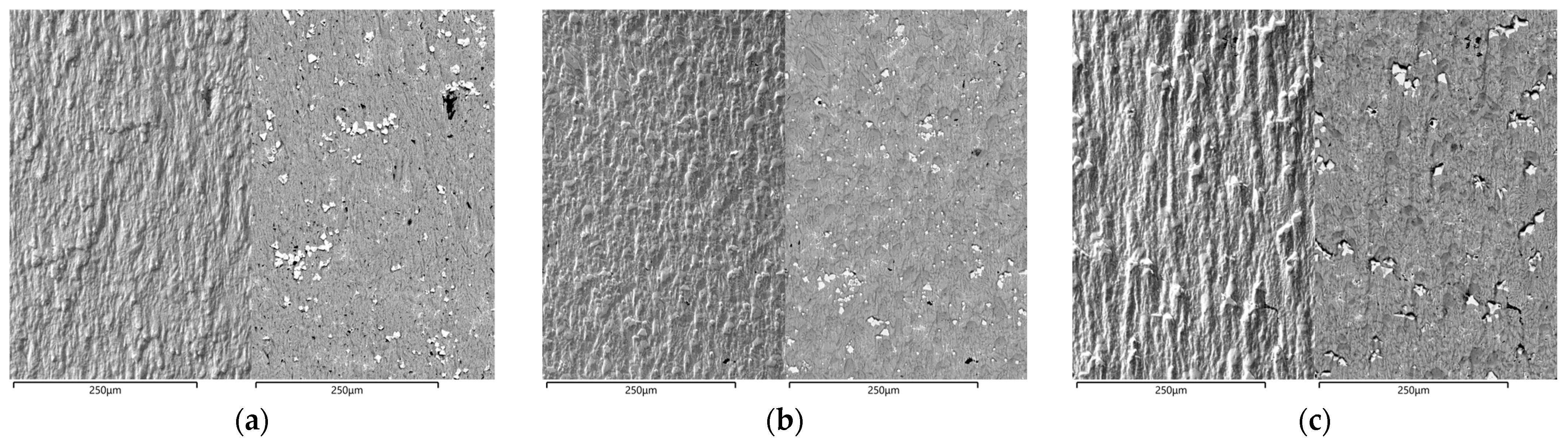
- the proposed heat treatments, i.e., tempering and destabilization, changed the hardness and the microstructure of the HCCI; nevertheless, the effects on the erosion resistance were minor compared to the contribution of the erodent particle size;
- -
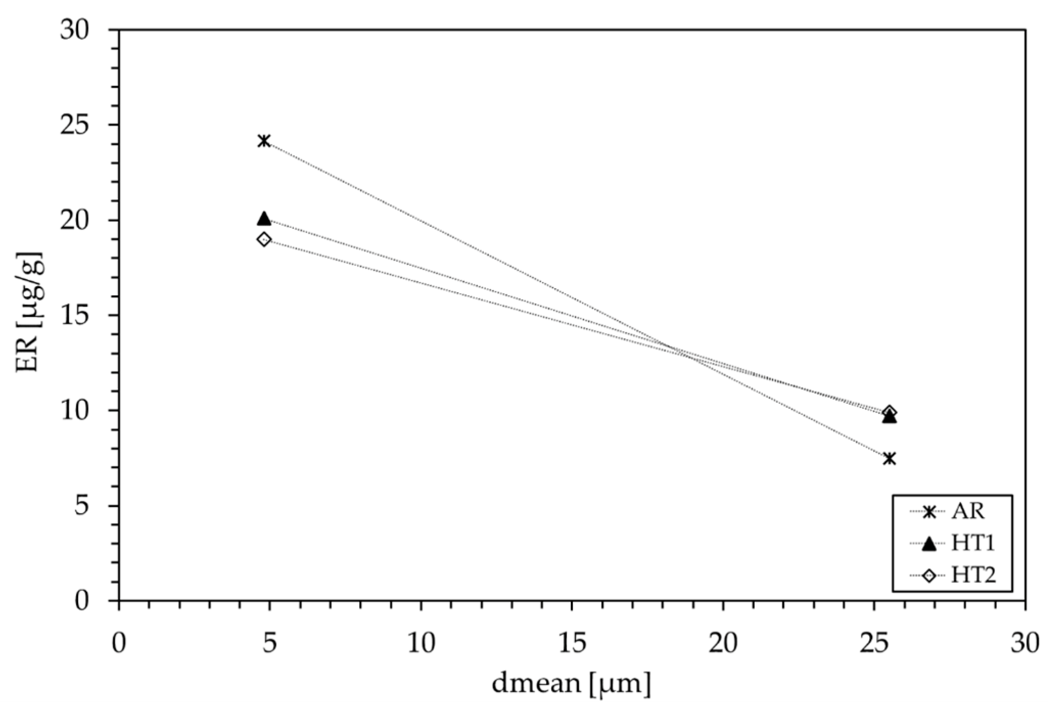
- the ER values decreased with increasing the mean diameter of the erodent, indicating that the severity of the erosive phenomenon is heavier for the smaller erodent’s mean particle diameter;
- -
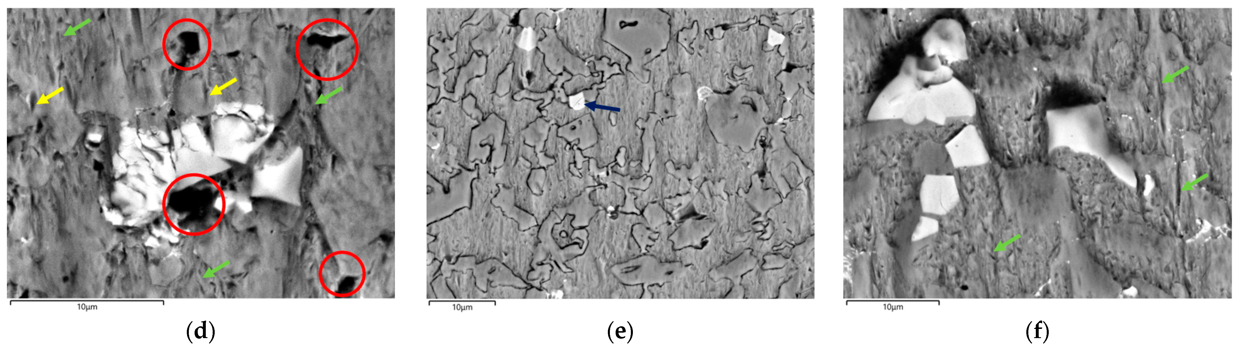
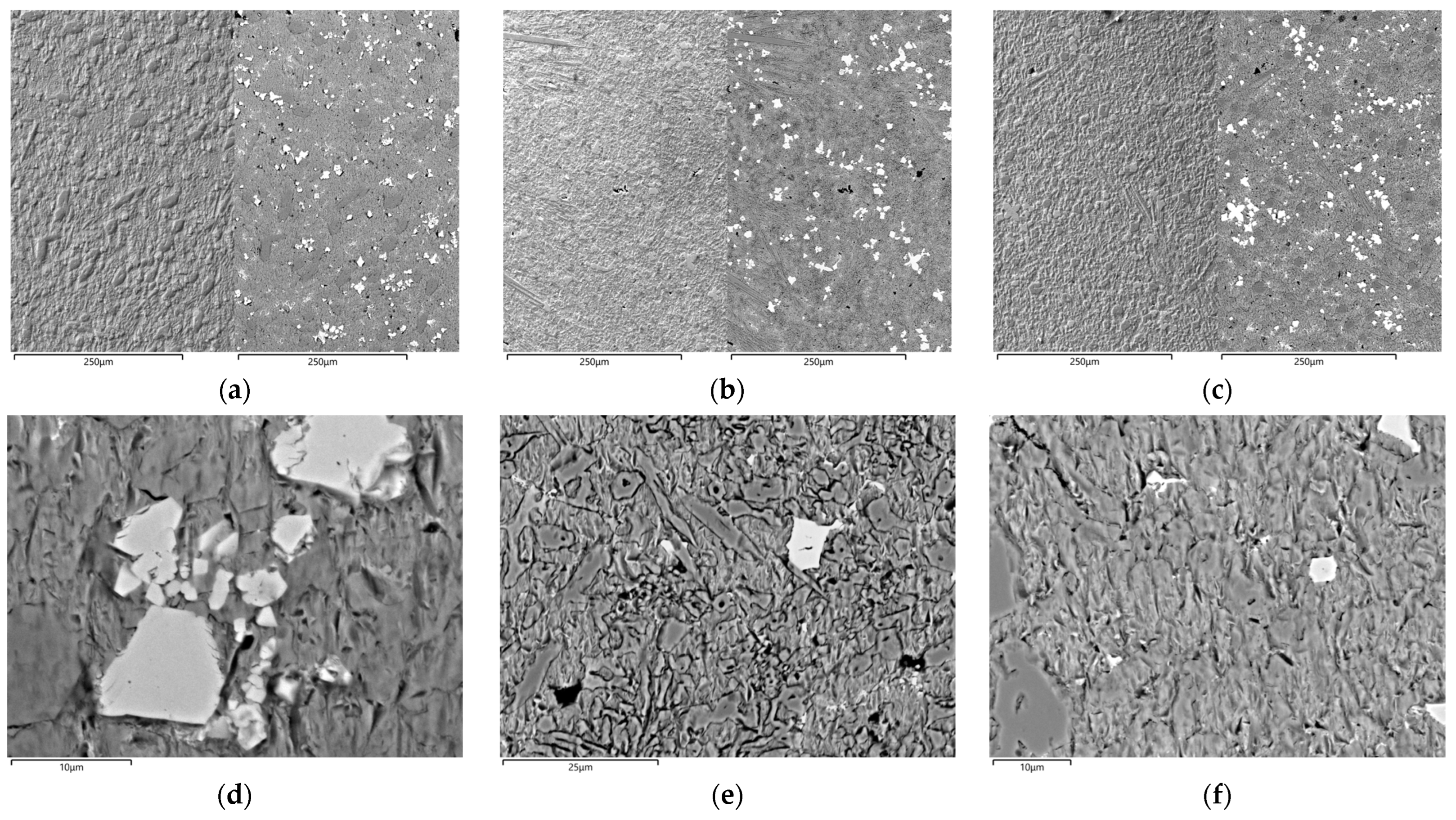
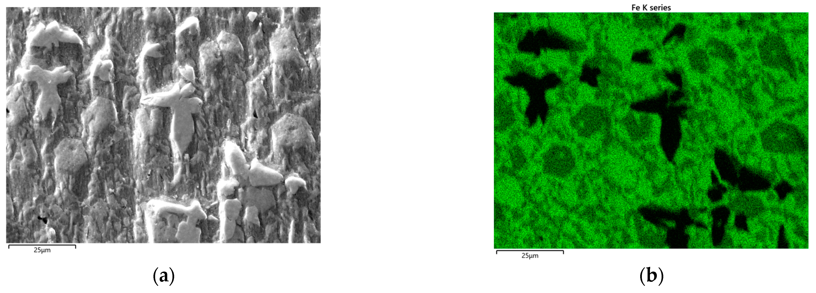
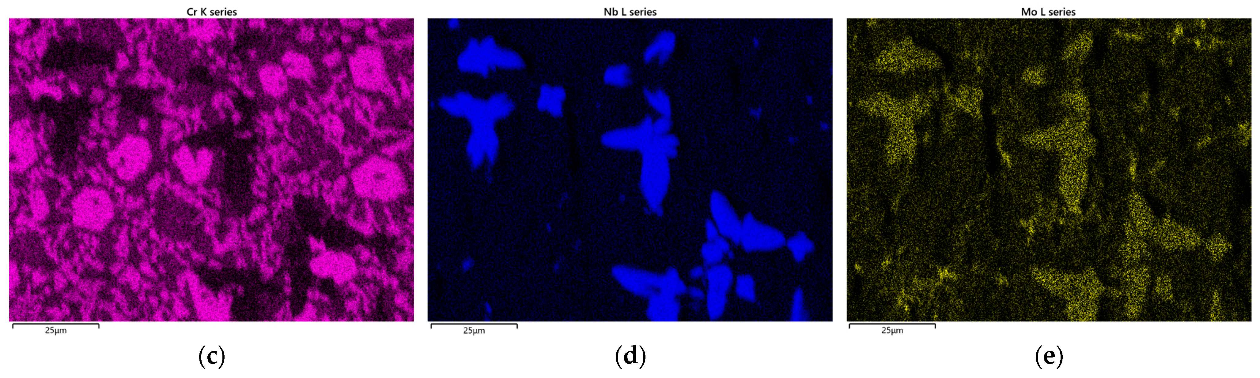
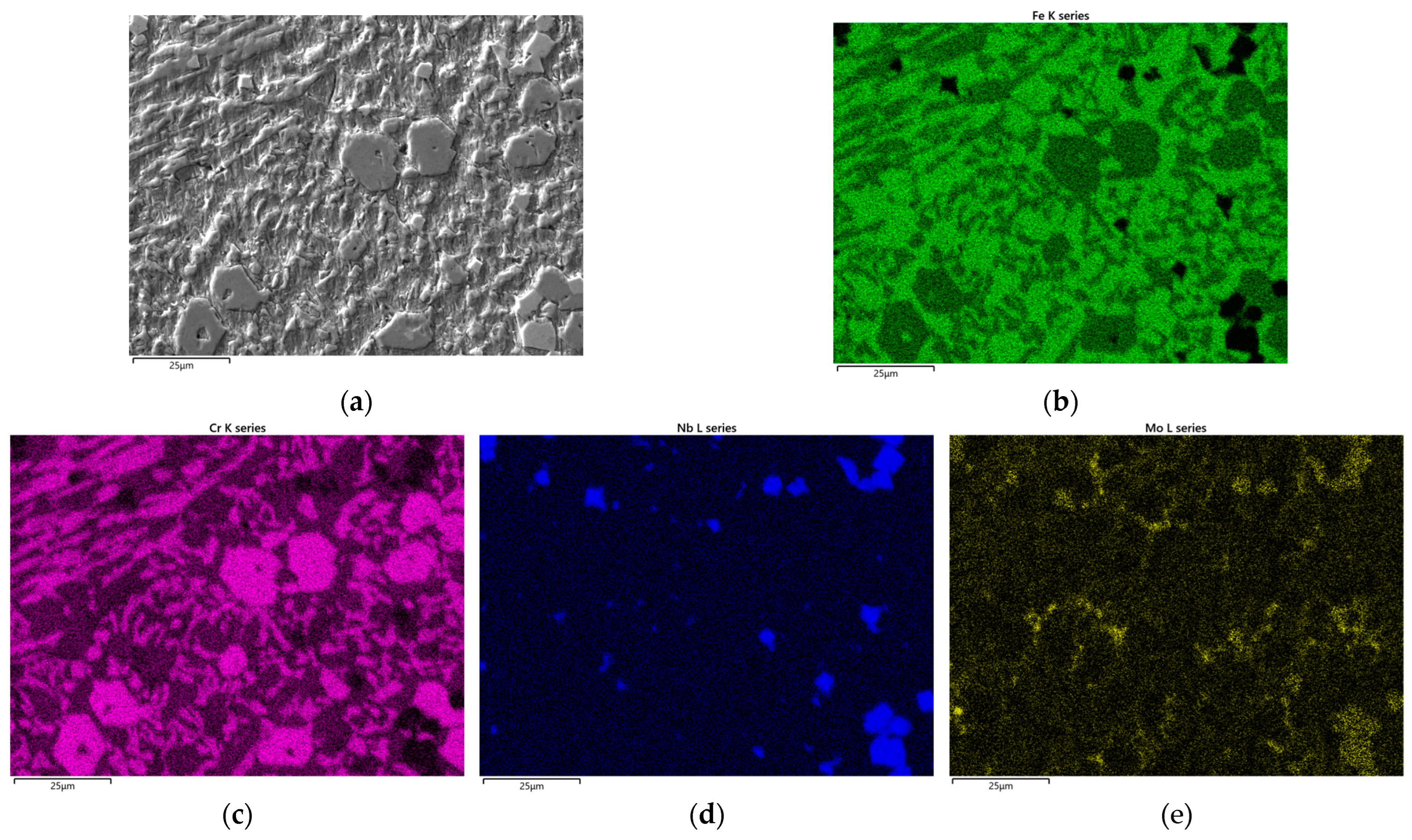
- from the analysis of the worn surfaces, the role of the microstructure in the erosion mechanisms was deepened: Nb-rich carbides act as a barrier to plowing. When the mean diameter of the erodent is lower than the edge-to-edge distances between the carbide and its adjacent ones, they were fractured and tended to fall off. In addition, the plastic deformation of the matrix is remarkable. Conversely, for a higher mean diameter of the erodent, the impact on the substrate was faced by a greater number of carbides, resulting in lower ER values;
- -
- the experimental findings suggested that the contribution of the mean diameter of the erodent is predominant compared to the substrate conditions.
Author Contributions
Funding
Institutional Review Board Statement
Informed Consent Statement
Data Availability Statement
Acknowledgments
Conflicts of Interest
References
- Ranjan, R.; Kumar Das, A. Protection from corrosion and wear by different weld cladding techniques: A review. Mater. Today Proc. 2022, 57, 1687–1693. [Google Scholar] [CrossRef]
- Tandon, D.; Li, H.; Pan, Z.; Yu, D.; Pang, W. A Review on Hardfacing, Process Variables, Challenges, and Future Works. Metals 2023, 13, 1512. [Google Scholar] [CrossRef]
- Badisch, E.; Roy, M. Hardfacing for Wear, Erosion and Abrasion. In Surface Engineering for Enhanced Performance against Wear; Springer Vienna: Vienna, Austria, 2013; pp. 149–191. [Google Scholar]
- Garbade, R.R.; Dhokey, N.B. Overview on Hardfacing Processes, Materials and Applications. IOP Conf. Ser. Mater. Sci. Eng. 2021, 1017, 012033. [Google Scholar] [CrossRef]
- Budinski, K.G.; Budinski, S.T. Tribomaterials: Properties and Selection for Friction, Wear, and Erosion Applications; ASM International: Almere, The Netherlands, 2021; ISBN 9781627083218. [Google Scholar]
- Venkatesh, B.; Sriker, K.; Prabhakar, V.S.V. Wear Characteristics of Hardfacing Alloys: State-of-the-art. Procedia Mater. Sci. 2015, 10, 527–532. [Google Scholar] [CrossRef]
- Lin, C.-M.; Chang, C.-M.; Chen, J.-H.; Hsieh, C.-C.; Wu, W. Microstructural Evolution of Hypoeutectic, Near-Eutectic, and Hypereutectic High-Carbon Cr-Based Hard-Facing Alloys. Metall. Mater. Trans. A 2009, 40, 1031–1038. [Google Scholar] [CrossRef]
- Buytoz, S. Microstructural properties of M7C3 eutectic carbides in a Fe–Cr–C alloy. Mater. Lett. 2006, 60, 605–608. [Google Scholar] [CrossRef]
- Fan, C.; Chen, M.-C.; Chang, C.-M.; Wu, W. Microstructure change caused by (Cr,Fe)23C6 carbides in high chromium Fe–Cr–C hardfacing alloys. Surf. Coat. Technol. 2006, 201, 908–912. [Google Scholar] [CrossRef]
- Liu, S.; Zhou, Y.; Xing, X.; Wang, J.; Ren, X.; Yang, Q. Growth characteristics of primary M7C3 carbide in hypereutectic Fe-Cr-C alloy. Sci. Rep. 2016, 6, 32941. [Google Scholar] [CrossRef]
- Eshed, E.; Choudhuri, D.; Osovski, S. M7C3: The story of a misunderstood carbide. Acta Mater. 2022, 235, 117985. [Google Scholar] [CrossRef]
- Ma, S.; Xing, J.; He, Y.; Li, Y.; Huang, Z.; Liu, G.; Geng, Q. Microstructure and crystallography of M7C3 carbide in chromium cast iron. Mater. Chem. Phys. 2015, 161, 65–73. [Google Scholar] [CrossRef]
- Lee, S.; Choo, S.-H.; Kim, N.J.; Baek, E.-R.; Ahn, S. Correlation of microstructure and fracture toughness in high-chromium white iron hardfacing alloys. Metall. Mater. Trans. A 1996, 27, 3881–3891. [Google Scholar] [CrossRef]
- Tabrett, C.P.; Sare, I.R.; Ghomashchi, M.R. Microstructure-property relationships in high chromium white iron alloys. Int. Mater. Rev. 1996, 41, 59–82. [Google Scholar] [CrossRef]
- Chung, R.J.; Tang, X.; Li, D.Y.; Hinckley, B.; Dolman, K. Microstructure refinement of hypereutectic high Cr cast irons using hard carbide-forming elements for improved wear resistance. Wear 2013, 301, 695–706. [Google Scholar] [CrossRef]
- Ibrahim, M.M.; El-Hadad, S.; Mourad, M. Enhancement of wear resistance and impact toughness of as cast hypoeutectic high chromium cast iron using niobium. Int. J. Cast Met. Res. 2018, 31, 72–79. [Google Scholar] [CrossRef]
- Chatterjee, S.; Pal, T.K. Solid particle erosion behaviour of hardfacing deposits on cast iron—Influence of deposit microstructure and erodent particles. Wear 2006, 261, 1069–1079. [Google Scholar] [CrossRef]
- Sapate, S.G.; RamaRao, A.V. Erosive wear behaviour of weld hardfacing high chromium cast irons: Effect of erodent particles. Tribol. Int. 2006, 39, 206–212. [Google Scholar] [CrossRef]
- Jindal, C.; Singh Sidhu, B.; Kumar, P.; Singh Sidhu, H. Performance of hardfaced/heat treated materials under solid particle erosion: A systematic literature review. Mater. Today Proc. 2022, 50, 629–639. [Google Scholar] [CrossRef]
- Tarodiya, R.; Levy, A. Surface erosion due to particle-surface interactions—A review. Powder Technol. 2021, 387, 527–559. [Google Scholar] [CrossRef]
- Fortini, A.; Suman, A.; Zanini, N.; Cruciani, G. Erosive Wear Behavior of High-Chromium Cast Iron: Combined Effect of Erodent Powders and Destabilization Heat Treatments. Coatings 2022, 12, 1218. [Google Scholar] [CrossRef]
- Kibble, K.A.; Pearce, J.T.H. Influence of Heat Treatment on the Microstructure and Hardness of 19% High-chromium Cast Irons. Cast Met. 1993, 6, 9–15. [Google Scholar] [CrossRef]
- Karantzalis, A.E.; Lekatou, A.; Diavati, E. Effect of Destabilization Heat Treatments on the Microstructure of High-Chromium Cast Iron: A Microscopy Examination Approach. J. Mater. Eng. Perform. 2009, 18, 1078–1085. [Google Scholar] [CrossRef]
- Karantzalis, A.E.; Lekatou, A.; Mavros, H. Microstructural Modifications of As-Cast High-Chromium White Iron by Heat Treatment. J. Mater. Eng. Perform. 2009, 18, 174–181. [Google Scholar] [CrossRef]
- Lin, C.-M.; Chang, C.-M.; Chen, J.-H.; Wu, W. The effects of additive elements on the microstructure characteristics and mechanical properties of Cr–Fe–C hard-facing alloys. J. Alloys Compd. 2010, 498, 30–36. [Google Scholar] [CrossRef]
- Li, P.; Yang, Y.; Shen, D.; Gong, M.; Tian, C.; Tong, W. Mechanical behavior and microstructure of hypereutectic high chromium cast iron: The combined effects of tungsten, manganese and molybdenum additions. J. Mater. Res. Technol. 2020, 9, 5735–5748. [Google Scholar] [CrossRef]
- Fortini, A.; Suman, A.; Zanini, N. An experimental and numerical study of the solid particle erosion damage in an industrial cement large-sized fan. Eng. Fail. Anal. 2023, 146, 107058. [Google Scholar] [CrossRef]
- ISO 6507:2018; Metallic Materials—Vickers Hardness Test—Part 1: Test Method. ISO: Geneve, Switzerland, 2018.
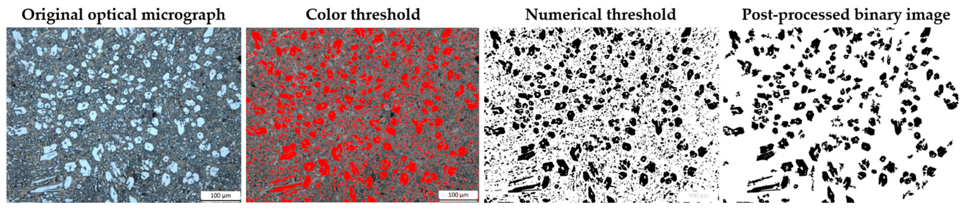
- Schneider, C.A.; Rasband, W.S.; Eliceiri, K.W. NIH Image to ImageJ: 25 years of image analysis. Nat. Methods 2012, 9, 671–675. [Google Scholar] [CrossRef] [PubMed]
- ASTM G76-07; Standard Test Method for Conducting Erosion Tests by Solid Particle Impingement Using Gas Jets. ASTM International: West Conshohocken, PA, USA, 2013.
- Fortini, A.; Suman, A.; Vulpio, A.; Merlin, M.; Pinelli, M. Microstructural and Erosive Wear Characteristics of a High Chromium Cast Iron. Coatings 2021, 11, 490. [Google Scholar] [CrossRef]
- ISO 12103-1:2016; Road Vehicles Test Contaminants for Filter Evaluation Part 1: Arizona Test Dust. ISO: Geneve, Switzerland, 2016.
- Casari, N.; Fortini, A.; Pinelli, M.; Suman, A.; Vulpio, A.; Zanini, N. Measurement approaches for the analysis of soil layer by microparticle adhesion. Measurement 2022, 187, 110185. [Google Scholar] [CrossRef]
- Wiengmoon, A. Carbides in high chromium cast irons. Naresuan Univ. Eng. J. 2011, 6, 64–71. [Google Scholar]
- Filipovic, M.; Kamberovic, Z.; Korac, M.; Gavrilovski, M. Microstructure and mechanical properties of Fe–Cr–C–Nb white cast irons. Mater. Des. 2013, 47, 41–48. [Google Scholar] [CrossRef]
- Sapate, S.G.; Rama Rao, A.V. Effect of carbide volume fraction on erosive wear behaviour of hardfacing cast irons. Wear 2004, 256, 774–786. [Google Scholar] [CrossRef]
- Tabrett, C.P.; Sare, I.R. Effect of high temperature and sub-ambient treatments on the matrix structure and abrasion resistance of a high-chromium white iron. Scr. Mater. 1998, 38, 1747–1753. [Google Scholar] [CrossRef]
- Yawei, L.; Wei, L.; Penghui, Y.; Hanguang, F.; Wenhang, Y.; Tounan, J.; Zhengyang, C. Microstructure Evolution and Hardness of Hypereutectic High Chromium Cast Iron after Tempering. J. Mater. Eng. Perform. 2023. [Google Scholar] [CrossRef]
- Powell, G.L.F.; Laird, G. Structure, nucleation, growth and morphology of secondary carbides in high chromium and Cr-Ni white cast irons. J. Mater. Sci. 1992, 27, 29–35. [Google Scholar] [CrossRef]
- Suman, A.; Vulpio, A.; Fortini, A.; Fabbri, E.; Casari, N.; Merlin, M.; Pinelli, M. Experimental analysis of micro-sized particles time-wise adhesion: The influence of impact velocity and surface roughness. Int. J. Heat Mass Transf. 2021, 165, 120632. [Google Scholar] [CrossRef]
- Lindsley, B.A.; Marder, A.R. The effect of velocity on the solid particle erosion rate of alloys. Wear 1999, 225–229, 510–516. [Google Scholar] [CrossRef]
- Goodwin, J.E.; Sage, W.; Tilly, G.P. Study of Erosion by Solid Particles. Proc. Inst. Mech. Eng. 1969, 184, 279–292. [Google Scholar] [CrossRef]
- Oka, Y.I.; Yoshida, T. Practical estimation of erosion damage caused by solid particle impact. Wear 2005, 259, 102–109. [Google Scholar] [CrossRef]
- Gaqi, Y.; Kusumoto, K.; Shimizu, K.; Purba, R.H. Effect of Carbide Orientation on Wear Characteristics of High-Alloy Wear-Resistant Cast Irons. Lubricants 2023, 11, 272. [Google Scholar] [CrossRef]
- Rajicic, B.M.; Maslarevic, A.; Bakic, G.M.; Maksimovic, V.; Djukic, M.B. Erosion Wear Behavior of High Chromium Cast Irons. Trans. Indian Inst. Met. 2023, 76, 1427–1437. [Google Scholar] [CrossRef]

| Composition (wt.%)—Fe Balance | |||||||
|---|---|---|---|---|---|---|---|
| C | Mn | Si | Cr | Mo | Nb | W | V |
| 4.15 | 0.56 | 1.08 | 21.04 | 2.78 | 4.09 | 0.86 | 0.69 |
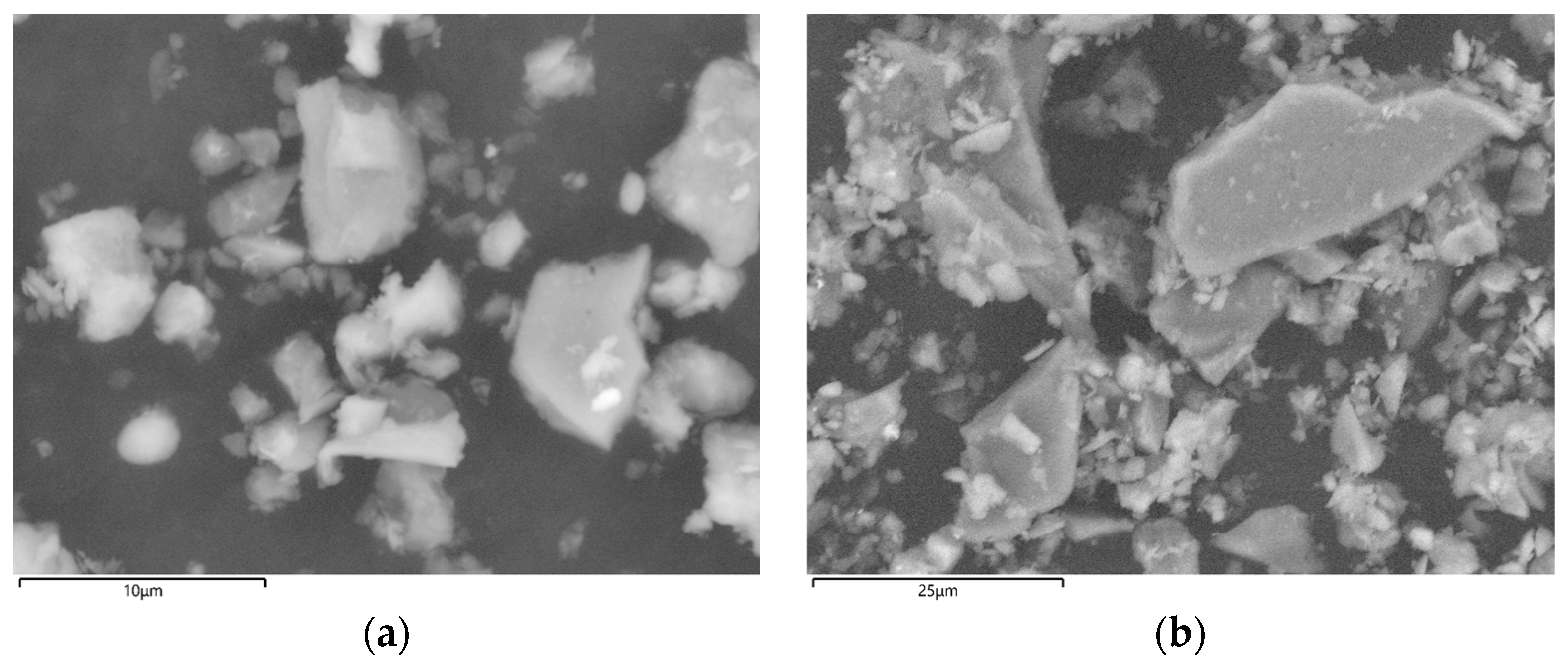
| Test Parameters | UF Powder (dmean = 4.8 µm) | M Powder (dmean = 25.5 µm) |
|---|---|---|
| Air mass flow [kg/s] | 0.0036 | 0.0003 |
| Flow rate [L/min] | 186 | 8.2 |
| Particle impact velocity [m/s] | 205 | 15.9 |
Disclaimer/Publisher’s Note: The statements, opinions and data contained in all publications are solely those of the individual author(s) and contributor(s) and not of MDPI and/or the editor(s). MDPI and/or the editor(s) disclaim responsibility for any injury to people or property resulting from any ideas, methods, instructions or products referred to in the content. |
© 2024 by the authors. Licensee MDPI, Basel, Switzerland. This article is an open access article distributed under the terms and conditions of the Creative Commons Attribution (CC BY) license (https://creativecommons.org/licenses/by/4.0/).
Share and Cite
Suman, A.; Fortini, A. Effects of Heat Treatment and Erosion Particle Size on Erosion Resistance of a Hypereutectic High-Chromium Cast Iron. Coatings 2024, 14, 66. https://doi.org/10.3390/coatings14010066
Suman A, Fortini A. Effects of Heat Treatment and Erosion Particle Size on Erosion Resistance of a Hypereutectic High-Chromium Cast Iron. Coatings. 2024; 14(1):66. https://doi.org/10.3390/coatings14010066
Chicago/Turabian StyleSuman, Alessio, and Annalisa Fortini. 2024. "Effects of Heat Treatment and Erosion Particle Size on Erosion Resistance of a Hypereutectic High-Chromium Cast Iron" Coatings 14, no. 1: 66. https://doi.org/10.3390/coatings14010066
APA StyleSuman, A., & Fortini, A. (2024). Effects of Heat Treatment and Erosion Particle Size on Erosion Resistance of a Hypereutectic High-Chromium Cast Iron. Coatings, 14(1), 66. https://doi.org/10.3390/coatings14010066