Article

The Behavior of TiAlN and TiAlCrSiN Films in Abrasive and Adhesive Tribological Contacts

1
Research Institute for Innovative Surfaces FINO, Aalen University, Beethovenstr. 1, D-73430 Aalen, Germany
2
Walter AG, Derendinger Str. 53, D-72072 Tübingen, Germany
3
Materials Research Institute Aalen, Aalen University, Beethovenstr. 1, D-73430 Aalen, Germany
*
Author to whom correspondence should be addressed.
Coatings 2023, 13(9), 1603; https://doi.org/10.3390/coatings13091603
Submission received: 7 August 2023 / Revised: 31 August 2023 / Accepted: 6 September 2023 / Published: 14 September 2023
(This article belongs to the Special Issue Mechanical Properties and Tribological Behavior of Alloy/Coatings)

Abstract

:
Chromium and silicon are often introduced to increase the performance of TiAlN hard coatings in dry tribological contacts. The addition of Cr and Si during a high-power impulse magnetron sputtering (HiPIMS) deposition process leads to high-quality TiAlCrSiN films. In this paper, the analysis of friction and wear of these films is conducted by oscillation tribometry under dry conditions with a subsequent mapping of the surface topography. Both abrasion- and adhesion-dominated conditions are realized using different steel counter bodies. Oscillation-frequency-dependent experiments show a significant impact of the compositional variation on friction and wear. It is shown that the TiAlCrSiN coating investigated has a higher coefficient of friction and a lower wear resistance compared to counterparts made of 100Cr6. The friction coefficient could be reduced by using a V2A counterpart. The results can be understood in terms of a reduced adhesion of both oxidic and metallic wear debris at the TiAlCrSiN surface. The study provides valuable progress towards the development of advanced cutting tools, e.g., for stainless steel.

1. Introduction

The outstanding properties of hard-coated surfaces have led to numerous novel developments in the field of wear protection in recent years. Wear-resistive surfaces made from transition-metal carbides, nitrides and oxides exhibit promising characteristics to substantially increase the lifetime of surfaces under mechanical loads [1]. For many years, TiAlN has played a prominent role as a coating material because of its outstanding hardness and wear resistance. Such coatings are usually deposited by vacuum-based processes. Among the numerous deposition techniques, the most frequently used ones are direct current (DC) and radio frequency (RF) sputtering [2,3]. More recently, high-power impulse magnetron sputtering (HiPIMS) has been established as well [3,4,5,6]. Here, high ionization degrees lead to an optimized film quality. In addition, arc deposition [6,7,8] or chemical vapor deposition (CVD) [9,10] can be used to end up with high-quality coatings as well. A recent alternative to vacuum deposition that might become important in some cases in the near future is a production route via additive manufacturing. In these cases, e.g., carbide surfaces with extremely large lifetimes can be prepared [11].
The outstanding properties of TiAlN coatings on various materials for the production of surfaces with extreme wear resistance have been studied in detail [12], in particular with respect to the used deposition method [13,14] or in view of potential applications [15,16]. Most frequently, the lifetime enhancing performance of hard coatings is tested in tribological tests using dry contacts, i.e., in absence of a lubricant, where maximum mechanical wear is created, and the performance of the coating can easily be extracted [16,17,18,19]. The characteristics of the tribological contact are in that case mostly given by the choice of the counter-body material: Aluminum oxide creates severe damage due to its large hardness (two-body abrasion), 100Cr6 steel counter bodies supply in many cases hard iron oxide abrasion particles leading to a significant increase in wear rates (three-body abrasion) and, finally, the material of stainless steel counter bodies is transferred to the surface creating an adhesive wear scenario. The two latter cases are intensively considered in this work.
A valuable way to realize wear-resistant surfaces can be the reduction in friction in the contact. In that case, the mechanical work in the testing routine that is responsible for the damage is reduced. Carbon-rich MoC, MoCN and multilayer MoC/MoCN coatings exhibit self-lubricating properties during tribological loading. By adding carbon to molybdenum-containing coatings, the coefficient of friction (COF) and the wear rate can be significantly reduced. In the case of MoC/MoCN multilayers, the COF as well as the wear rate are significantly reduced compared to an uncoated surface [20]. Additional silver in MoN coatings can serve as a source for the formation of a lubricant phase during the tribological load [21,22]. Finally, so-called “Chameleon” coatings can be produced by adding various additives. Such coatings are characterized by their ability to adapt to the respective environment and provide the best possible performance. Multilayer systems such as WC/WS2/DLC and ZrO2-Y2O3/Au/DLC/MoS2 combine ceramic, metals, carbon and dichalcogenide materials in an individual nanocomposite coating [23].
In addition to self-lubricating coatings, friction and wear-resistant properties can be improved by surface microstructures. Here, laser surface texturing (LST) [24,25,26] or mechanical microimprinting [27,28,29] can be used for the realization. Microstructuring can be performed both before and after the deposition of the hard coating. In many cases the introduction of surface structures on a microscale leads to significantly reduced friction and wear. A remaining question is whether the compositional or topographical modification is the method of choice to reduce friction and wear in particular contacts or if both concepts might be combined [30].
In this work, the question is addressed of whether the addition of Cr and Si to TiAlN coatings can improve friction and wear in dry tribological contacts, in particular, when considering the case of abrasion-dominated and adhesion-dominated contacts, respectively.

2. Materials and Methods

Two types of wear-resistive nitride films were deposited on cobalt-bound tungsten carbide (WC/Co) substrates containing 8 wt% Co.
As hard material, two compositions were chosen: first, a Ti0.4Al0.6N (TiAlN) single layer and, second, a Ti0.4Al0.35Cr0.1Si0.15N (TiAlCrSiN) layer with a Ti0.4Al0.6N interlayer underneath. The application as carried out on an S3p-capable system from Oerlikon Balzers, Germany, using HiPIMS.
Before coating, the substrates underwent ultrasonic cleaning in an ethanol bath for several minutes and were also plasma-etched for a few minutes upon being introduced into the process chamber. The Ti0.4Al0.6N layer was directly deposited onto the substrate without an interlayer. The process gas used was argon with a pressure of pAr = 4.2 × 10⁻³ mbar, and the total pressure during deposition was p = 6.0 × 10⁻³ mbar. A bias voltage of −40 V was applied to the substrate whilst coating the films at a temperature of 450 °C. The films had a thickness of 3 ± 0.25 µm.
In the case of the second coating, a Ti0.4Al0.6N interlayer with a thickness of approximately 1 µm was first deposited. The same parameters as described earlier were used for this step. Subsequently, a TiAlCrSiN layer was deposited on top. The argon pressure used was pAr = 4.2 × 10⁻³ mbar, with a total pressure of p = 6.2 × 10⁻³ mbar. The applied bias voltage was −40 V for the initial ten minutes, then it was increased to −50 V for the remaining duration of the deposition. The parameters used for the film deposition are summarized in Table 1. A detailed description of the film deposition can be found in [31]. The thickness of the TiAlCrSiN layer was also 3 ± 0.25 µm.
The coating’s hardness was analyzed via nanoindentation using a Picodentor HM500 from Helmut Fischer GmbH in Sindelfingen, Germany. HIT (0.015/20/10/20) = 18.7 ± 1 GPa defined the penetration hardness of the TiAlN layers, whereas HIT (0.015/20/10/20) = 16.4 ± 1 GPa was used for the TiAlCrSiN layer.
The next stage involved researching friction and wear in normal TiAlN and advanced TiAlCrSiN hard coatings. Dry contacts with spherical counter bodies under heavy load were employed. The experiments were conducted through the utilization of oscillation tribometry.
Two tribological scenarios were considered, namely, contacts dominated by abrasion and adhesion, respectively. This was achieved by utilizing two distinct steel balls as counter bodies for tribological testing. The “abrasive contact” employed 100Cr6 steel (DIN 1.3205), which is known to generate a substantial number of third particles during dry oscillation tribometry [28]. Due to the substantial energy input into the interface between the film and counter body, oxidation occurs [28], resulting in a cluster of tough particles that greatly enhance the film’s abrasion. The second tribocontact examined exchanged the 100Cr6 steel ball with a V2A stainless-steel ball (DIN 1.4301) as a counter body. Here, the primary wear mechanism differed. The alloy’s high concentration of transition metal atoms resulted in a significant increase in the adhesion forces between the counter body and nitride film, leading to the observed agglomeration of “V2A-material” on the nitride surface. This transfer of material from the counter body to the film surface was identified as the wear mechanism that determined the lifetime; thus, it is referred to as “adhesive contact”. Figure 1 provides a simplified illustration of the tribocontacts studied in this research.
The wear characteristics of the nitride surfaces were analyzed using the “SRV 3” series tribometer from Optimol Instruments Prüftechnik GmbH, Munich, Germany. The experiments were conducted at a constant temperature of 50 °C using unlubricated ball-on-plane oscillatory tribology, with steel balls of diameter d = 10 mm as counter bodies. Since a severe wear scenario was required, an unusually heavy normal load of FN = 50 N was applied, and an oscillatory motion with a stroke of 1 mm parallel to the surface was utilized. Relative velocity measurements were taken at different oscillation frequencies of f = 2, 4, 10 and 20 Hz (corresponding to maximum velocities of 6.3 mm/s to 63 mm/s) to explore their role. The total number of cycles was kept constant at n = 3600 in all cases. This led to test durations of t = 1800 s, 900 s, 360 s and 180 s, respectively.
Each combination of two different counter bodies (100Cr6 steel and V2A stainless steel) and two different types of coatings (TiAlN and TiAlCrSiN) underwent experiments. Subsequently, white-light interferometry (WLI) was used to examine the damaged surfaces, which provided the topography of the resulting wear scars. Electron-dispersive X-ray spectroscopy (EDX) was employed to analyze the distribution of elements inside the wear track. Technical abbreviations are explained upon first use. Bias and subjective evaluations were excluded.

3. Results

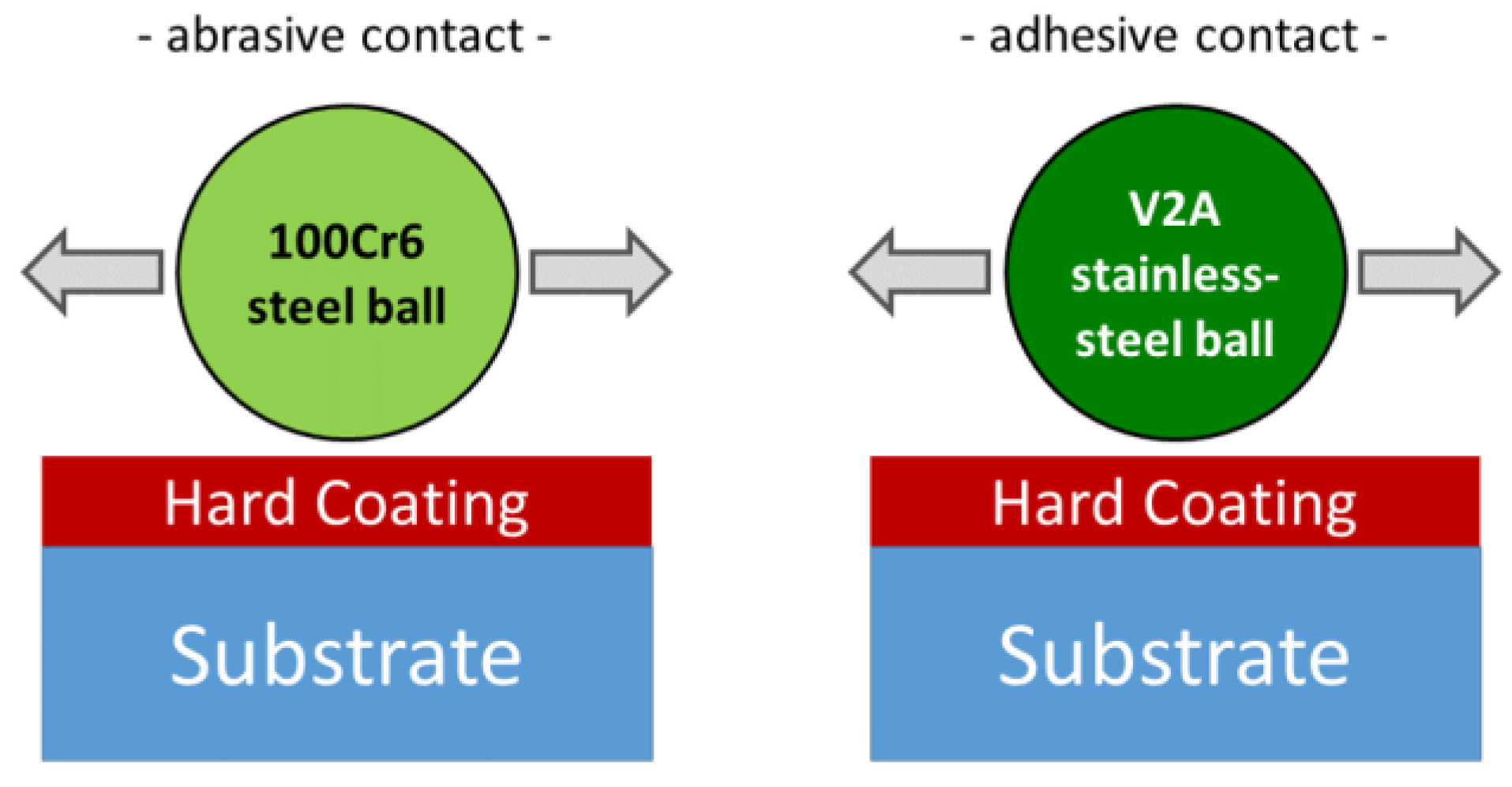
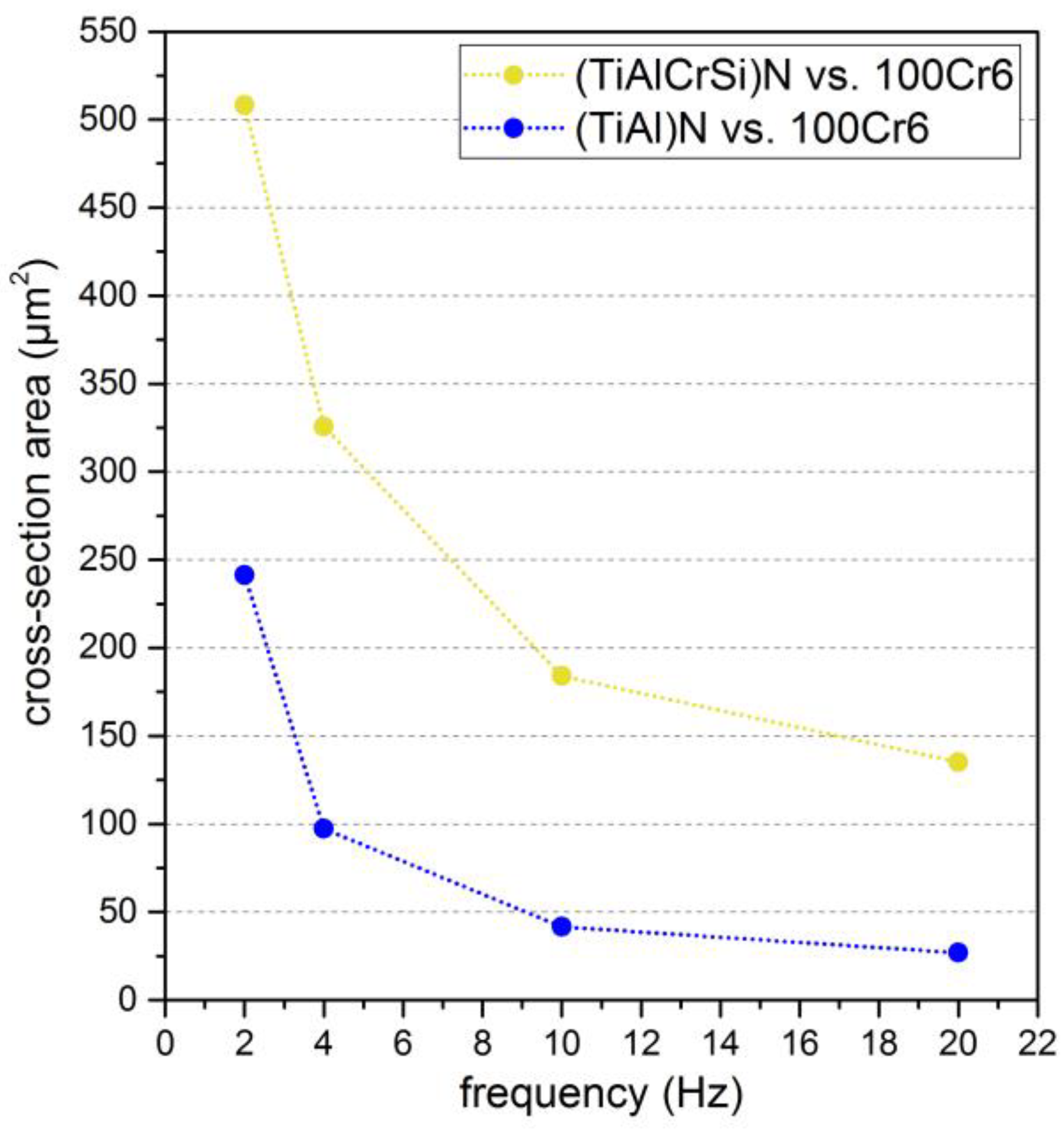
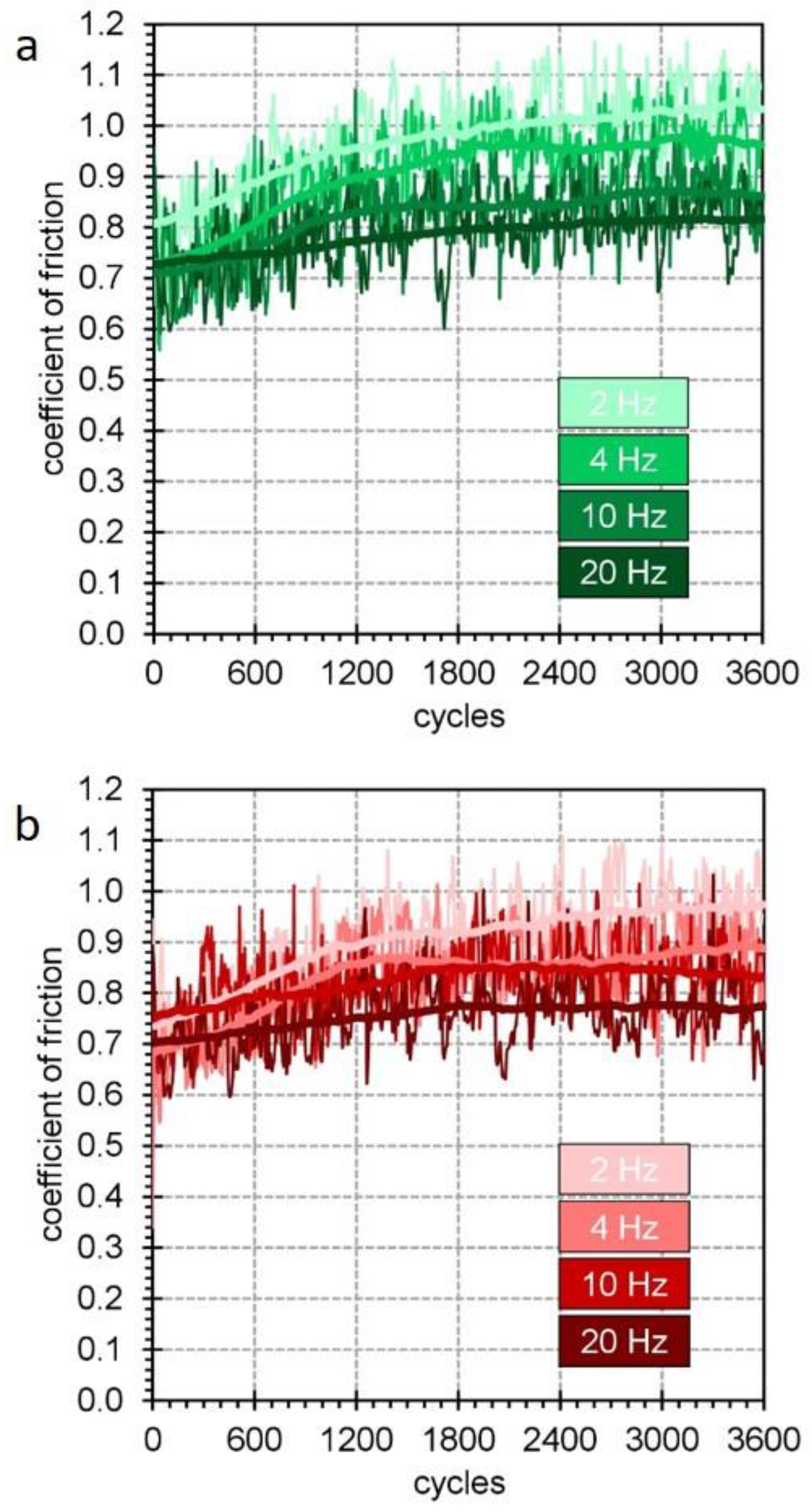
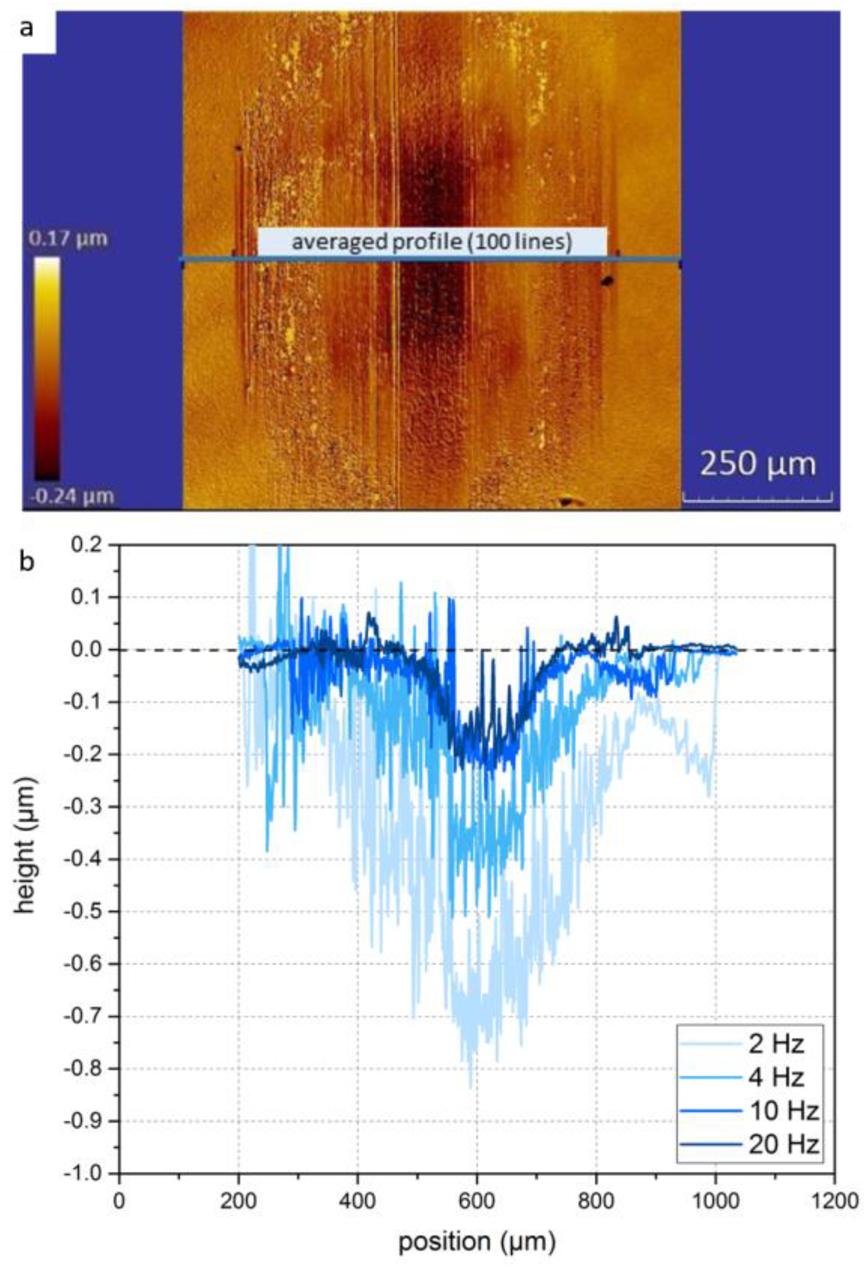
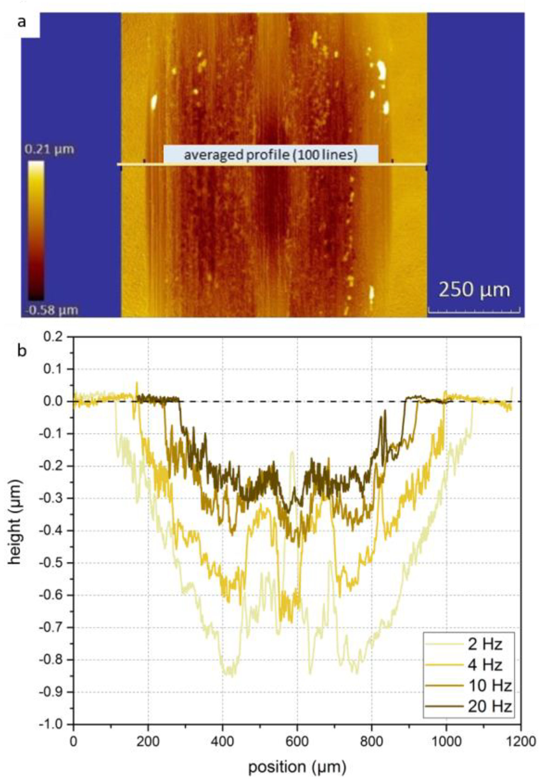
3.1. Abrasive Contacts

The first part was dedicated to “abrasive contacts”, tribological contacts under high load exhibiting a wear process dominated by three-body abrasion. In an according oscillation experiment under dry conditions, hard iron oxide particles were formed that were significantly responsible for the occurring wear. We performed systematic experiments determining the COF between f = 2 Hz and f = 20 Hz at a constant load of FN = 50 N. This corresponded to Hertzian pressures of about pH = 2520 MPa for TiAlN/100Cr6 and pH = 2370 MPa for TiAlCrSiN/100Cr6. In all cases, 3600 measurement cycles were completed during testing.
Figure 2 shows the obtained values of the COF in a dry contact vs. a 100Cr6 ball with a diameter of d = 10 mm. The blue curves in the top panel depict the COF for the reference surface, a Ti0.4Al0.6N coating.
The measurements at the TiAlN surface provided similar data curves for all used oscillation frequencies from f = 2 Hz to f = 20 Hz. All curves show a prominent running-in period that extends over the first about 500 to 800 cycles. Here, a rather high and strongly varying COF of µ ≈ 0.7 to 1.0 is found. After that initial period, a drop of µ towards a lower, basically constant COF of µ = 0.6 to 0.7 is found in all measured curves from 4 Hz to 20 Hz. Only the light-blue curve obtained at f = 2 Hz shows slightly larger values combined with a more pronounced variation of µ. A slight increase in µ is found for all curves with an increasing measurement time.
The equivalent experiment was performed on the surface coated with the TiAlCrSiN film. The results are depicted in the bottom panel of Figure 2. The corresponding curves are displayed in yellow. In that case, the results for the compositionally modified TiAlCrSiN film draw a different picture. There are significant changes of the obtained friction curves when varying the oscillation frequency from f = 2 Hz to f = 20 Hz. For f = 2 Hz the COF curve shows an extended running-in period up to about 1300 cycles. Subsequently, a high and basically constant COF of about µ = 1.0 is found. In addition, the curve exhibits a shape that is much “noisier” compared to the TiAlN film case. Increasing the frequency leads to three effects: First, the duration of the running-in period decreases, second the “noisiness” is reduced and, finally, the COF decreases as well. At f = 10 Hz and f = 20 Hz we find a COF from 0.6 to 0.65 which is in the same range as the COFs found for the standard TiAlN film.
For a more systematic point of view, all the acquired friction curves were averaged after the individual running-in period ended. The obtained average values of this so called “steady-state region” are summarized in Figure 3.
This representation reveals large and systematic differences in the friction properties of the two wear-resistive films being part of an abrasive tribocontact. The standard TiAlN film (blue curve) exhibits small and basically frequency-independent COF values from 0.6 to 0.7. µ(f) has a minimum at intermediate frequencies and slightly increases both towards low and high frequencies. The results found for the TiAlCrSiN film are displayed in yellow and show a distinctly different behavior. The lowest COF of µ = 0.6 is measured at the highest oscillation frequency of f = 20 Hz. With the decreasing testing frequency, a strong increase up to µ = 0.95 is found.
The frequency-dependent behavior of the TiAlSiCrN/100Cr6 tribocontact is completely different from that found for the TiAlN/100Cr6 case. The COF of TiAlCrSiN at f = 2 Hz is dramatically larger as µ = 0.7 than in the case of the TiAlN film at f = 2 Hz. However, at f = 20 Hz, this changes, and the yellow curve lies slightly below the blue one: we find a reduced friction for the film with a modified composition, although the effect might be too small to be really significant.
The observed increase in the COF towards small frequencies, i.e., small relative velocities are often found. Small oscillation frequencies favor events of static friction. Possible resting times for the static periods increase when reducing the testing frequency. This leads to an increase in the measured COF values since the static COF is always larger than the dynamic COF. This model is supported by the increase in noisiness of the low-frequency curves in Figure 2, where occurring peaks in the COF refer to static events. Additionally, the composition of the third particle ensemble will change with the increasing frequency. An increase in the relative velocity leads to an enhanced energy deposition in the contact area. This supports tribo-oxidation processes at the surface of abrasion particles. Since the third particle abrasion is the dominant wear mechanism, this process will undergo changes with the frequency increase leading to a change in particle composition [32].
To collect further information on the mechanisms responsible and to correlate the results of the friction experiments with the occurring wear, a detailed look into the wear scar was conducted. We used quantitative white-light interferometry to analyze the wear track with a high spatial resolution. In particular, the shape of the topography profile across the track was extracted, and the wear volume was derived from these data.
For the representation of the obtained wear profiles in all considered cases shown in Figure 2, we used identical colors. Figure 4 displays the results for TiAlN. A WLI image obtained at f = 10 Hz is shown at the top. Profiles that are extracted along the horizontally oriented line are depicted for different oscillation frequencies at the bottom. All profiles were averaged in the vertical direction over an interval of 100 µm.
The wear profiles show for all frequencies a significant removal of film material since the dominant wear process in the dry contact against a 100Cr6 steel ball is the abrasion of the hard coating. A closer look reveals that a complex wear landscape develops that does not reproduce the spherical shape of the counter body at all. Besides a minimum at the center of the track, all profiles show additional minima located near the edge of the wear track. This is a clear attribute of a third-body abrasion caused by hard particles originated from the ball-shaped counter body [18]. Owing to the nonplanar geometry of the mechanical contact, a driving force appears that causes a motion of particles towards the rim of the contact. There, the particles agglomerate and cause severe damage to the TiAlN surface. In addition, it is noticed that the abrasion volume systematically decreases with the increasing testing frequency. This can be immediately identified when considering the width and depth of the profiles in Figure 4, where both properties continuously decrease with the increasing testing frequency. However, the difference between the occurring wear in the case of the 10 and 20 Hz measurements is very small.
The presence of abrasion particles in the wear track provided by the 100Cr6 counter body was revealed by a scanning electron microscopy (SEM) analysis with elemental mapping by EDX. The results are displayed in Figure 5.
In the low-magnification SEM image, the horizontally oriented wear track is clearly seen in the center of the image. The corresponding elemental mappings for iron, aluminum and oxygen show a high concentration of iron oxide inside the track that forms a layer parallel to the oscillation direction. This proves that the material of the counter body is oxygenized during the wear process, accumulates in the track and forms a discontinuous layer.
When comparing these results with the ones obtained at the TiAlCrSiN surfaces under equivalent testing, a series of differences are apparent. An interferometry image and corresponding wear profiles are displayed in Figure 6; the axes are chosen equivalently.
First, we find a significant increase in both width and depth of the individual wear tracks indicating a strong increase in the abrasion volume. Second, a qualitative change in the shape of the profiles occurs. In the case of the yellow profiles, there are no prominent wear scars at the edges of the track as seen for the unmodified surface. However, also in this case, additional minima occur. Here, these minima are found in the vicinity of the center of the profile close to but distinctly different from the point of largest Hertzian pressure. The profiles referring to large frequencies f = 10 Hz and f = 20 Hz hardly show additional minima.
Further information was again collected by an SEM/EDX analysis of the wear tracks. The results are depicted in Figure 7.
In contrast to the TiAlN surface presented in Figure 5, the wear track (marked by an additional dashed line) can hardly be seen in the SEM image, although the wear depth is much larger. There is no iron oxide layer formed inside the track, the surface inside the track has the same composition as the film. Additionally, a large number of volatile abrasion particles can be found in the vicinity of the track. The elemental mapping identified iron and oxygen; no elements of the film constituents (Al, Ti, Cr, Si) were detected by EDX.
For a better comparison of the wear volumes, Figure 8 provides the cross section of the wear profiles extracted from Figure 4 and Figure 6. The colors were chosen as above: the blue curve refers to the TiAlN film, the yellow curve to TiAlSiCrN.
Both curves basically show the same frequency dependence: a monotonous decrease in the wear volume with the increasing frequency. For the whole considered frequency range, the wear volume of the TiAlCrSiN surface is significantly larger than of the standard TiAlN film. The variation of the film composition leads to a distinct loss of wear resistance in the case of the considered abrasion-dominated dry contact. Interestingly, the relative performance of the TiAlCrSiN film is worst at high frequencies. Here, the wear volume is about a factor of six larger compared to the standard film. At f = 2 Hz and 4 Hz, this factor is smaller than two. This is particularly noteworthy when comparing this result to the average friction values displayed in Figure 4: the COF hardly shows any differences between TiAlN and TiAlCrSiN at high frequencies.
To generally judge the quality of the coated surfaces, the wear rate can be extracted. In the case of the blue data point at f = 2 Hz, the wear rate was calculated to be about 2.0 × 10⁻¹⁵ m3/Nm. This value is comparable to high-quality wear-resistive coatings under dry testing [33].
An understanding of the observed friction and wear behavior can be developed when considering the nature of the tribocontact: there is some particle-mediated abrasion that basically avoids the direct contact of the tribopartners.
Thus, the mechanisms are related to two interfaces, first, between the counter body and the ensemble of abrasion particles and second, between the ensemble of abrasion particles and the coated surface.
The results of Figure 5 and Figure 7 reveal that the composition of the abrasion particles does not change when replacing the TiAlN surface by TiAlCrSiN. In all cases, iron oxide particles are found provided by the counter body and oxidized during wear testing. Note, that this is consistent with results obtained on MoN surfaces [30]. The interfaces between the counter body and abrasion particles are identical for the considered surfaces and thus cannot be the origin of the change in the tribological properties of the contact. This means the nitride surface and its interaction with the abrasion particles has to be considered. First, the reduced hardness of the TiAlCrSiN film can be responsible for a reduction in the wear resistance and directly explain larger wear volumes. However, an explanation of the changing ratio with the frequency of the wear volumes of both surfaces from roughly two at 2 Hz to about six at 20 Hz cannot be provided. A significant role is attributed to the formation of the iron oxide layer inside the wear track that is apparently found in Figure 5. This layer of high hardness acts as protective layer that effectively reduces the occurring wear and is the origin of the large difference of the wear rates at f = 20 Hz. The less-pronounced effect at lower frequencies is related to the reduced friction power at the interface that does not allow the formation of the protective iron oxide layer. The observed increase in the COF at high frequencies in the case of the TiAlN layer supports the formation of a surface layer with different friction properties.
The results in Figure 7 show that this protective layer apparently cannot form on the TiAlCrSiN surface. The addition of Cr and Si leads to a change in the surface properties (assumably the polar part of the surface energy) and thus avoids the deposition of adhesive iron oxides. The absence of the protective layer means an intense particle-induced abrasion as observed in the experiment.

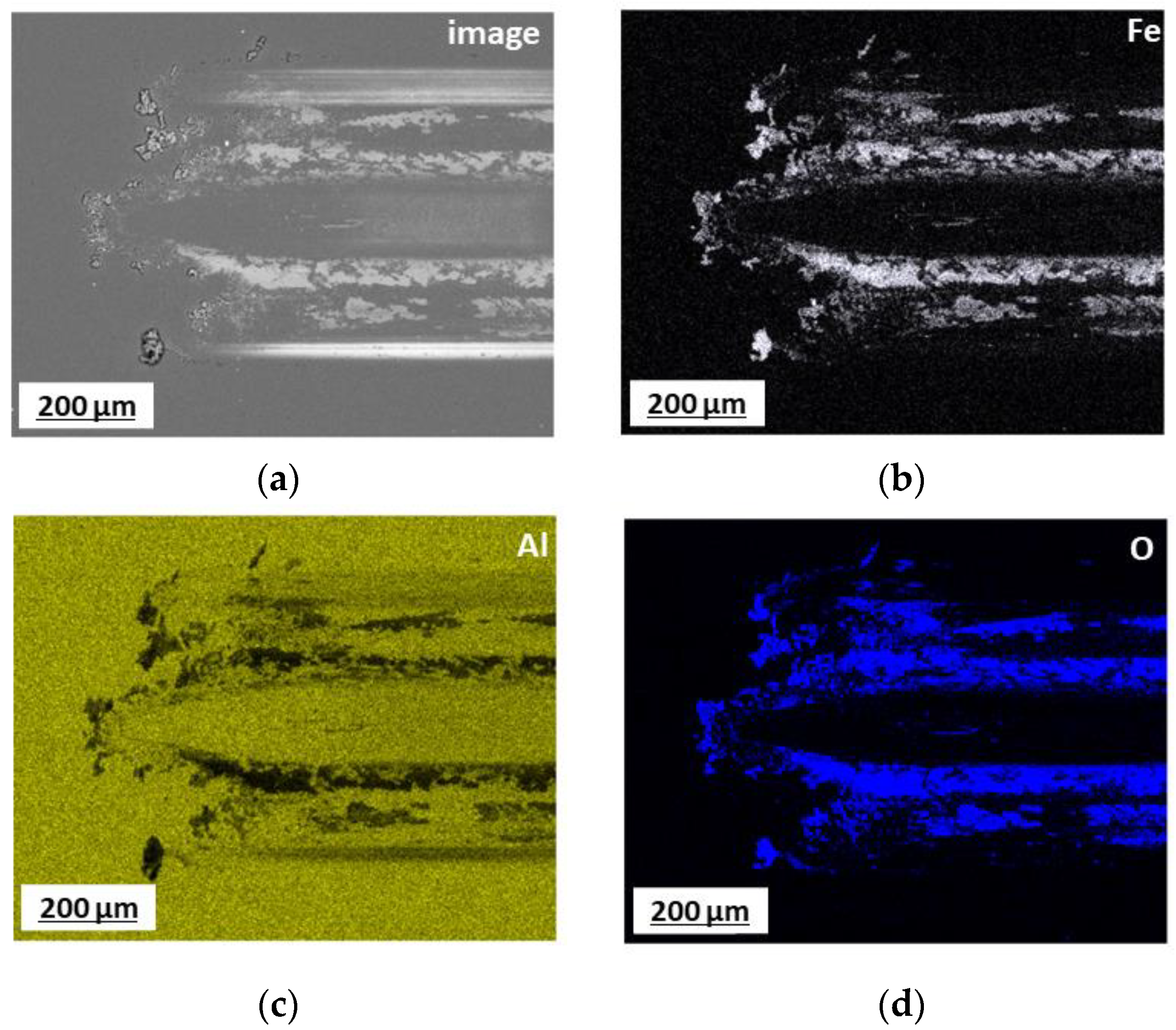
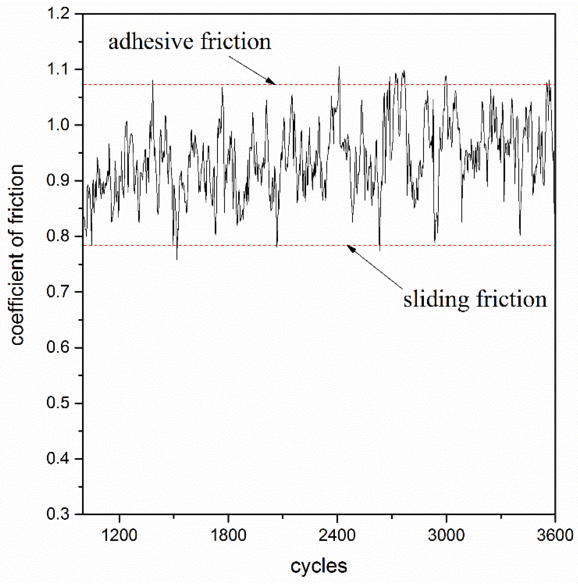
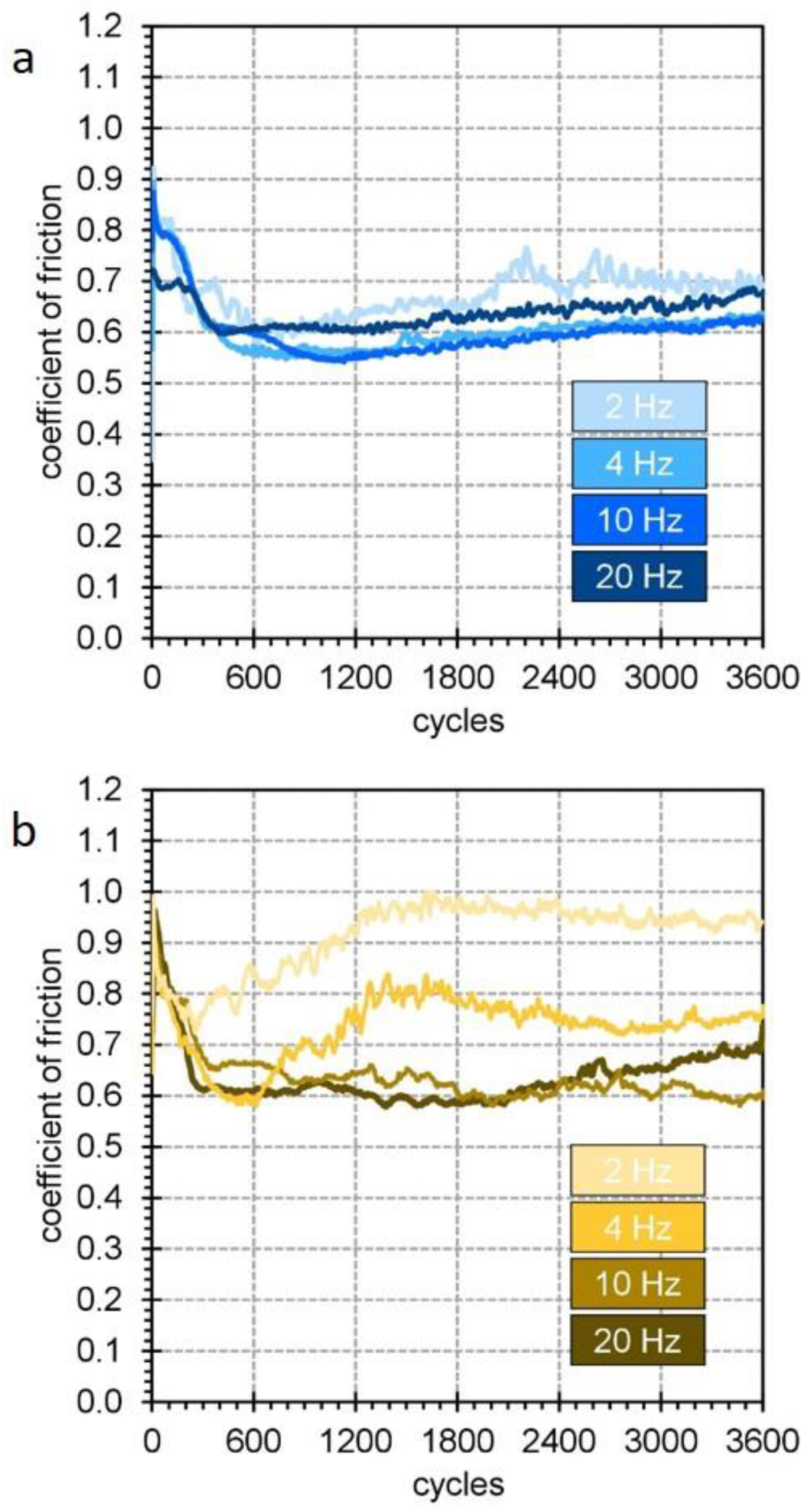
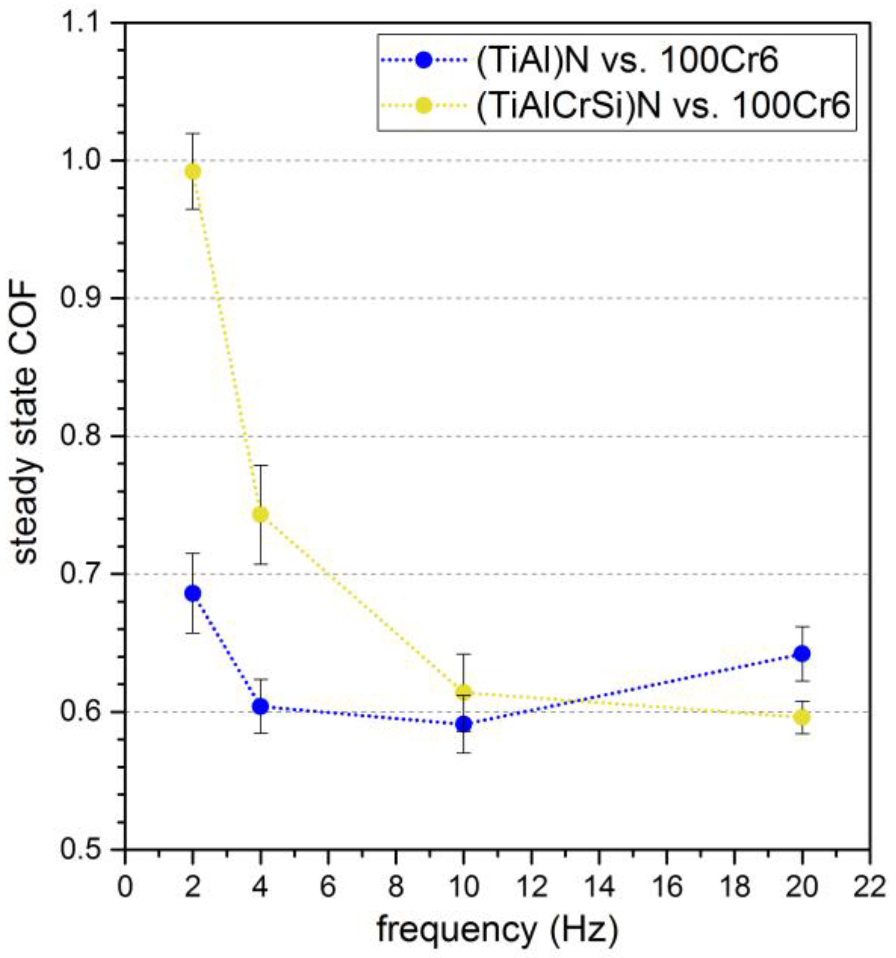
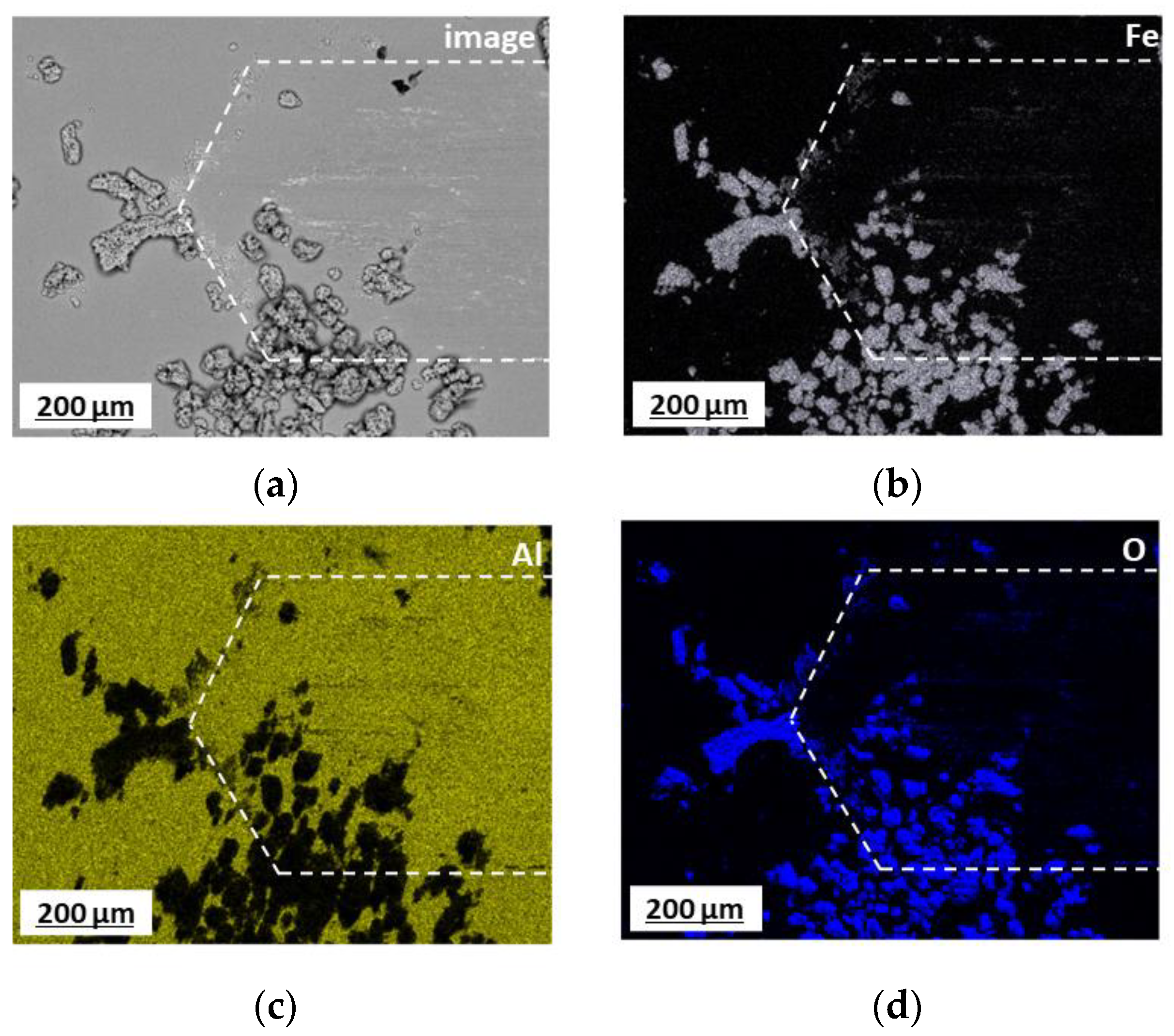
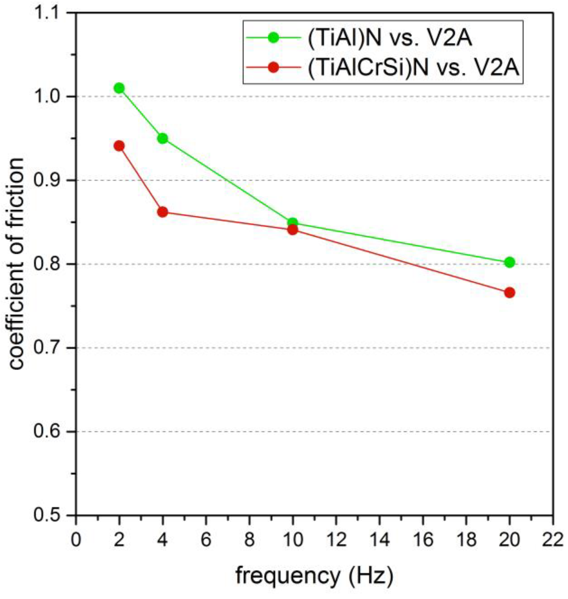
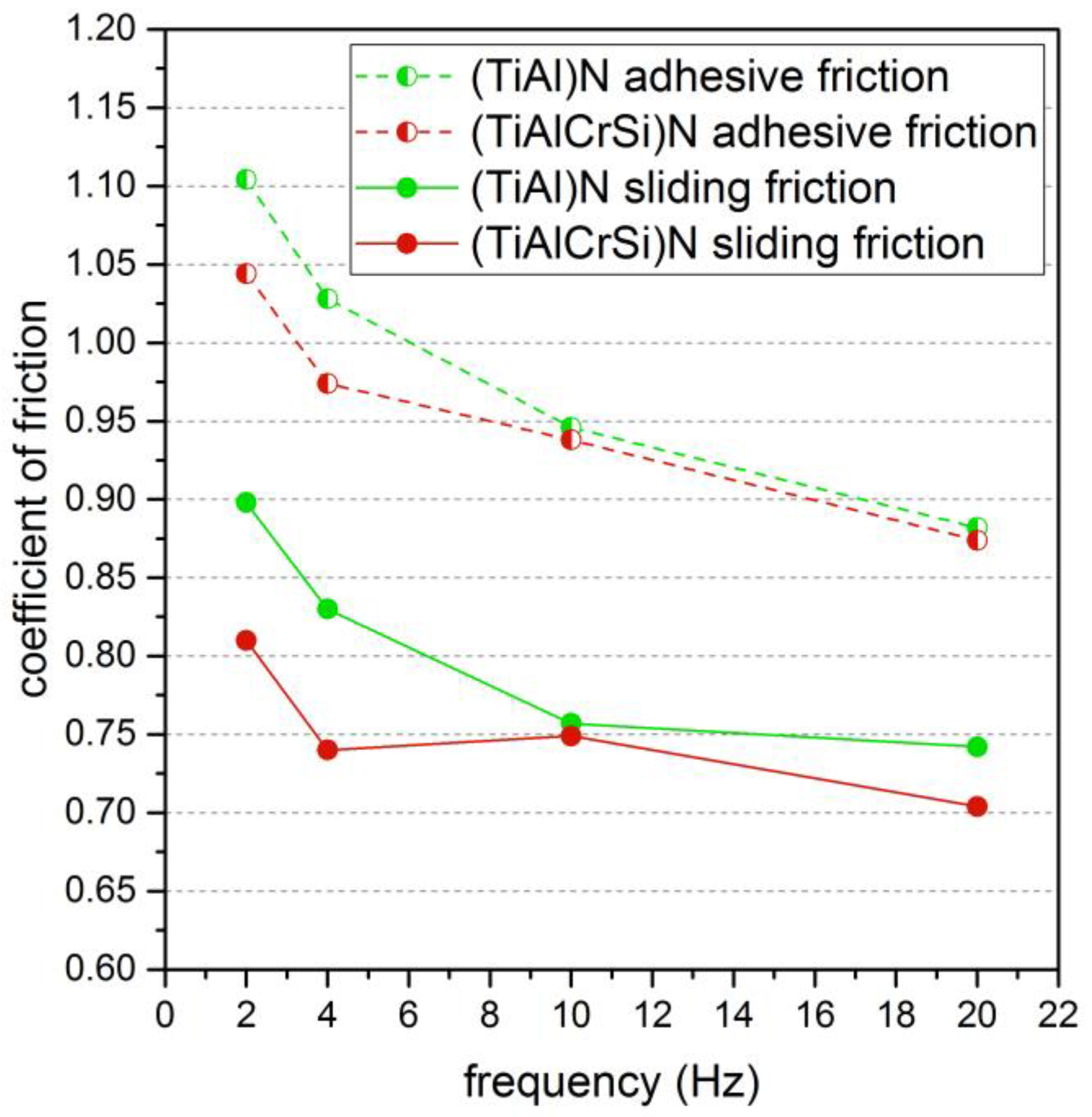
3.2. Adhesive Contacts

Equivalent investigations were performed for both coatings in a dry contact exhibiting an adhesion-dominated wear process. Here, a V2A stainless-steel counter body was used for the oscillation tribometry. This modified the Hertzian pressures to about pH = 2110 MPa for TiAlN/V2A and pH = 2010 MPa for TiAlCrSiN/V2A. The dominant wear mechanism was the deposition of metallic material of the counter body on the nitride surface. Figure 9 shows the measured COF under the same experimental conditions as chosen for the abrasive contact.
All obtained COF curves against the V2A counter bodies exhibit a pronounced “noisy” behavior. The experimental values statistically fluctuate with an amplitude of the order of µ = ±0.1. For a first comparison of the data at different frequencies, averaged curves were added as solid green/red lines to Figure 9.
Omitting the first 500 to 800 cycles as the running-in period, we find rather constant average values of the COF from µ = 0.8 to 1.0. This is significantly larger than the values found for the abrasive contact. In addition, we find a continuous decrease in the COF with the increasing oscillation frequency f. Replacing TiAlN by TiAlCrSiN under equivalent experimental conditions leads to similar results that are depicted in the bottom part of Figure 9. The curves look similar; again, a noisy and fluctuating behavior of the COF is found. The running-in period of about 500–800 oscillations remains the same, stable COF values in the steady state of µ = 0.7 to 0.9, a fluctuation amplitude of the order of µ = ±0.1 and a systematic decrease in the COF values towards higher frequencies draw a similar picture as found in the case of the TiAlN surface.
To evaluate whether the compositional variation leads to systematic changes of the friction conditions, the average values of all curves extracted after the running-in regime were plotted as function of frequency and are shown in Figure 10.
The comparison of both curves provides a number of parallels and differences. Both curves show a monotonous decrease in the COF with the increasing frequency, and for high frequencies of 10 and 20 Hz, both curves show similar values. A striking difference arises at low frequencies where the COF of the TiAlCrSiN surface is significantly smaller. The COF can be reduced in this frequency range by roughly 0.1.

4. Discussion

The general increase in the COF in the case of V2A compared to 100Cr6 can be explained by a significant stick–slip process that occurs in tribocontacts against V2A stainless steel. There, events of static and dynamic friction alternate [34]. Static or adhesive friction occurs due to local cold welding of the tribopartners. “Stick” refers to the state these connections persist in. The prevailing shear stress cracks the cold weld, and sliding occurs. This is described as “slip”. Consequently, data points are found that describe a static friction event and data points that refer to a sliding or dynamic friction. The change between adhesive and sliding friction can be seen from the abrupt jumps in the COF values during the tribometry measurement that occur in the case of V2A.
Since the adhesive friction coefficient is the larger one, we can identify the occurring maximums with the adhesive friction case and the minimums with the pure sliding friction.
As an example, a COF measurement of TiAlCrSiN against V2A is shown in Figure 11, where the running-in period is omitted. The measurement was carried out at a frequency of f = 2 Hz. At low frequencies, the lifetime of individual static and sliding events is large enough to extract data points corresponding to an individual friction event. The distance between the upper and lower limits of the data points represents the extreme cases of adhesive friction and sliding friction (dashed lines).
The so-determined values of adhesive and sliding friction were averaged for all measurements with V2A counter bodies and are shown in Figure 12 as a dashed curve for the adhesive friction and as a solid curve for the sliding friction for all measured frequencies from f = 2 Hz to 20 Hz.
In all cases, a reduction in the observed COFs is found with the increasing frequency. In addition, we find again a reduction in friction in the case of the TiAlCrSiN coatings, particularly at low frequencies. Interestingly, the reduction in friction is apparent in the adhesive case and even more pronounced in the sliding case. This means that additional Cr and Si influence both the cold-welding process that leads to the sticking event of the partners and the sliding event where, because of the adhesive character of the contact, material is transferred to the TiAlCrSiN surface. Since the adhesion of V2A will be provided by a shear process in the counter body, the question arises as to why the TiAlCrSiN coating shows a lower COF than the TiAlN surface.
An answer can be to consider the occurring wear processes. However, an equivalent analysis of wear volumes as that done in the abrasive contact does not appear meaningful because most of the material deposited during the adhesion process is V2A on V2A, at least after the first monolayer. This does not help to extract the role of the composition of the coating. Instead of that, a closer look into the wear scar was performed by scanning electron microscopy. An example of a surface where an adhesive wear process has taken place is shown in Figure 13.
Distinct regions of deposited metallic V2A steel can be identified in the electron micrograph by energy-dispersive X-ray spectroscopy. Here, the adhesion of V2A steel leads to agglomerations with a height of several micrometers. At the same time, it is seen that there is no full coverage of the surface. Only stainless-steel islands are formed, a large fraction of the surface consists of the uncovered coating material.
This provides an explanation for why the modified surface composition has an impact of the tribological properties during the whole testing time. As seen in the formation of an oxidic layer for 100 Cr6 counter bodies, the deposition of additional material is also modified when comparing TiAlN and TiAlCrSiN. Although when metallic material is deposited in the wear track, we again find that the addition of Cr and Si leads to a less sticky surface, and the agglomeration of metallic V2A steel inside the wear track is reduced. A reduced adhesion also reduces the measured friction because a notable contribution arises from the deformation of deposited material during the oscillatory test. The corresponding force scales with the amount of material in the contact area. The reduction in adhesion leads to a reduction in material that has to be deformed during oscillation tribometry. Thus, the composition of the coating directly affects the sliding COF, as seen in the analysis in Figure 12. A closer look at the COF data reveals that the difference between TiAlN and TiAlCrSiN evolves after the running-in period when enough metallic material sticks to the nitride surface. A detailed description of this process will be given in future experiments.

5. Conclusions

Wear-resistive TiAlCrSiN coatings were deposited on WC/Co hard metal substrates. In oscillation tribology experiments, the performance of these coatings was tested in dry contacts exhibiting abrasive and adhesive characteristics, respectively. The abrasive scenario was realized using counter bodies of 100Cr steel. During the abrasion process, hard oxide particles were generated that led to an increasing loss of material in the coating. It was found that the investigated TiAlCrSiN coating exhibited a higher friction and lower wear resistance in that case compared to a TiAlN coating. This was attributed to the formation of a sticky protection layer in the case of the TiAlN coating that significantly reduced wear. The formation of this oxidic layer was suppressed in the case of the TiAlCrSiN coating because the adhesion of oxides was reduced. When considering an adhesive contact that was realized using a V2A stainless-steel counter body, a different scenario occurred. The friction could be described by a stick–slip process, which resulted in an irregular behavior of alternating static and sliding friction events. The TiAlCrSiN coating showed a significant reduction in COF of approximately 20%, particularly at low test frequencies. The analysis of the static and sliding friction events showed that the addition of Cr and Si reduced both the static and sliding friction coefficients at low frequencies by 15 to 20%, depending on the frequency. The lower friction was also explained by a reduction in adhesion in this case of metallic materials due to the addition of Cr and Si to the coating. This result might lead to an increase in the lifetime of TiAlCrSiN-coated tools when machining stainless steel.

Author Contributions

Conceptualization, W.E., V.S. and J.A.; data curation, W.S., V.J., F.K., T.S. and J.A.; formal analysis, W.S., F.K. and J.A.; investigation, W.S., V.J. and T.S.; methodology, W.S., W.E., V.S., T.S. and J.A.; supervision, J.A.; visualization, W.S.; writing—original draft, W.S. and J.A.; writing—review and editing, F.K., W.E. and V.S. All authors have read and agreed to the published version of the manuscript.

Funding

This research received no external funding.

Institutional Review Board Statement

Not applicable.

Informed Consent Statement

Not applicable.

Data Availability Statement

The data that support the findings of this study are available from the corresponding author upon reasonable request.

Conflicts of Interest

The authors have no conflict to disclose.

References

  1. Jindal, P.C.; Santhanam, A.T.; Schleinkofer, U.; Shuster, A.F. Performance of PVD TiN, TiCN, and TiAlN coated cemented carbide tools in turning. Int. J. Refract. Met. Hard Mater. 1999, 17, 163–170. [Google Scholar]
  2. Min, Z.; Makino, Y.; Nose, M.; Nogi, K. Phase transition and properties of Ti-Al-N thin films prepared by r.f.-plasma assisted magnetron sputtering. Thin Solid Films 1999, 339, 203–208. [Google Scholar]
  3. Tillmann, W.; Grisales, D.; Stangier, D.; Thomann, C.-A.; Debus, J.; Nienhaus, A.; Apel, D. Residual stresses and tribomechanical behaviour of TiAlN and TiAlCN monolayer and multilayer coatings by DCMS and HiPIMS. Surf. Coat. Technol. 2021, 406, 126664. [Google Scholar] [CrossRef]
  4. Kuo, C.-C.; Lin, Y.-T.; Chan, A.; Chang, J.-T. High Temperature Wear Behavior of Titanium Nitride Coating Deposited Using High Power Impulse Magnetron Sputtering. Coatings 2019, 9, 555. [Google Scholar] [CrossRef]
  5. Azim, S.; Gangopadhyay, S.; Mahapatra, S.S.; Mittal, R.K. Performance evaluation of CrAlN and TiAlN coatings deposited by HiPIMS in micro drilling of a Ni-based superalloy. Surf. Coat. Technol. 2022, 449, 128980. [Google Scholar] [CrossRef]
  6. Alhafian, M.R.; Chemin, J.B.; Fleming, Y.; Bourgeois, L.; Penoy, M.; Useldinger, R.; Soldera, F.; Mücklich, F.; Choquet, P. Comparison on the structural, mechanical and tribological properties of TiAlN coatings deposited by HiPIMS and Cathodic Arc Evaporation. Surf. Coat. Technol. 2021, 423, 127529. [Google Scholar]
  7. Chaar, A.; Rogström, L.; Johansson-Jöesaar, M.; Barrirero, J.; Aboulfadl, H.; Schell, N.; Ostach, D.; Mücklich, F.; Odén, M. Microstructural influence of the thermal behavior of arc deposited TiAlN coatings with high aluminum content. J. Alloys Compd. 2021, 854, 157205. [Google Scholar] [CrossRef]
  8. Zhang, Z.; Zhang, L.; Yuan, H.; Qiu, M.; Zhang, X.; Liao, B.; Zhang, F.; Ouyang, X. Tribological Behaviors of Super-Hard TiAlN Coatings Deposited by Filtered Cathode Vacuum Arc Deposition. Materials 2022, 15, 2236. [Google Scholar] [CrossRef]
  9. Qiu, R.; Bäcke, O.; Stiens, D.; Janssen, W.; Kümmel, J.; Manns, T.; Andrén, H.-O.; Halvarsson, M. CVD TiAlN coatings with tunable nanolamella architectures. Surf. Coat. Technol. 2021, 413, 127076. [Google Scholar] [CrossRef]
  10. Ben Hassine, M.; Andrén, H.-O.; Iyer, A.H.; Lotsari, A.; Bäcke, O.; Stiens, D.; Janssen, W.; Manns, T.; Kümmel, J.; Halvarsson, M. Growth model for high-Al containing CVD TiAlN coatings on cemented carbides using intermediate layers of TiN. Surf. Coat. Technol. 2021, 421, 127361. [Google Scholar] [CrossRef]
  11. Köhn, F.; Sedlmajer, M.; Albrecht, J.; Merkel, M. Additive Manufacturing of Tungsten Carbide Surfaces with Extreme Wear Resistivity. Coatings 2021, 11, 1240. [Google Scholar] [CrossRef]
  12. Al-Bukhaiti, M.A.; Al-Hatab, K.A.; Tillmann, W.; Hoffmann, F.; Sprute, T. Tribological and mechanical properties of Ti/TiAlN/TiAlCN nanoscale multilayer PVD coatings deposited on AISI H11 hot work tool steel. Appl. Surf. Sci. 2014, 318, 180–190. [Google Scholar] [CrossRef]
  13. Huang, R.-X.; Qi, Z.-B.; Sun, P.; Wang, Z.-C.; Wu, C.-H. Influence of substrate roughness on structure and mechanical property of TiAlN coating fabricated by cathodic arc evaporation. Phys. Procedia 2011, 18, 160–167. [Google Scholar] [CrossRef]
  14. Zhang, J.; Gu, Y. Effect of Al/Ti ratio on the mechanical properties and tribological behaviours of TiAlN coatings deposited by multi-arc ion plating method. Proc. Inst. Mech. Eng. Part J. 2011, 225, 854–863. [Google Scholar] [CrossRef]
  15. Leyendecker, T.; Lemmer, O.; Esser, S.; Ebberink, J. The development of the PVD coating TiAlN as a commercial coating for cutting tools. Surf. Coat. Technol. 1991, 48, 175–178. [Google Scholar] [CrossRef]
  16. Zheng, G.; Zhao, G.; Cheng, X.; Xu, R.; Zhao, J.; Zhang, H. Frictional and wear performance of TiAlN/TiN coated tool against high-strength steel. Ceram. Int. 2018, 44, 6878–6885. [Google Scholar] [CrossRef]
  17. Resendiz-Calderon, C.D.; Farfan-Cabrera, L.I.; Gallardo-Hernandez, E.A. Friction and Wear of Metals under Micro-abrasion, Wet and Dry Sliding Conditions. J. Mater. Eng. Perform. 2020, 29, 6228. [Google Scholar] [CrossRef]
  18. Haus, L.; Wildfeuer, M.; Grochowski, J.-E.; Wöckel, J.; Müller, M.; Köhn, F.; Schulz, W.; Wüstefeld, C.; Rafaja, D.; Albrecht, J. Wear properties of carbon-rich tungsten carbide films. Wear 2021, 488–489, 204146. [Google Scholar] [CrossRef]
  19. Alisir, S.H.; Evrensel, D. Investigation into Coating Structure and Wear Environment Effects on Tribological Properties of Piston Ring Coated with Monolayer TiAlN and Multilayer TiN/TiAlN. J. Mater. Eng. Perform. 2022, 31, 1654–1666. [Google Scholar] [CrossRef]
  20. Kumar, D.D.; Hazra, S.; Panda, K.; Kuppusami, P.; Stimpel-Lindner, T.; Duesberg, G.S. Probing the Impact of Tribolayers on Enhanced Wear Resistance Behavior of Carbon-Rich Molybdenum-Based Coatings. ACS Appl. Mater. Interfaces 2022, 14, 26148–26161. [Google Scholar] [CrossRef]
  21. Ren, M.; Yu, H.-L.; Zhu, L.-N.; Li, H.-Q.; Xu, B.-S. Microstructure, mechanical properties and tribological behaviors of TiAlN-Ag composite coatings by pulsed magnetron sputtering method. Surf. Coat. Technol. 2022, 436, 128286. [Google Scholar] [CrossRef]
  22. Fenker, M.; Balzer, M.; Kellner, S.; Polcar, T.; Richter, A.; Schmidl, F.; Vitu, T. Formation of Solid Lubricants during High Temperature Tribology of Silver-Doped Molybdenum Nitride Coatings Deposited by dcMS and HIPIMS. Coatings 2021, 11, 1415. [Google Scholar] [CrossRef]
  23. Voevodin, A.; Zabinski, J. Laser surface texturing for adaptive solid lubrication. Wear 2006, 261, 1285–1292. [Google Scholar] [CrossRef]
  24. Gachot, C.; Rosenkranz, A.; Reinert, L.; Ramos-Moore, E.; Souza, N.; Müser, M.H.; Mücklich, F. Dry Friction between Laser-Patterned Surfaces: Role of Alignment, Structural Wavelength and Surface Chemistry. Tribol. Lett. 2013, 49, 193–202. [Google Scholar] [CrossRef]
  25. Da Silva, M.; Suarez, M.P.; Machado, A.R.; Costa, H.L. Effect of laser surface modification on the micro-abrasive wear resistance of coated cemented carbide tools. Wear 2013, 302, 1230. [Google Scholar] [CrossRef]
  26. Kümmel, J.; Braun, D.; Gibmeier, J.; Schneider, J.; Greiner, C.; Schulze, V.; Wanner, A. Study on micro texturing of uncoated cemented carbide cutting tools for wear improvement and built-up edge stabilization. J. Mater. Process. Technol. 2015, 215, 62–70. [Google Scholar] [CrossRef]
  27. Li, N.; Xu, E.; Liu, Z.; Wang, X.; Liu, L. Tuning apparent friction coefficient by controlled patterning bulk metallic glasses surfaces. Sci. Rep. 2016, 6, 39388. [Google Scholar] [CrossRef]
  28. Kommer, M.; Sube, T.; Richter, A.; Fenker, M.; Schulz, W.; Hader, B.; Albrecht, J. Enhanced wear resistance of molybdenum nitride coatings deposited by high power impulse magnetron sputtering by using micropatterned surfaces. Surf. Coat. Technol. 2018, 333, 1–12. [Google Scholar] [CrossRef]
  29. Gajrani, K.K.; Reddy, R.P.K.; Sankar, M.R. Tribo-mechanical and surface morphological comparison of untextured, mechanical micro-textured (MμT), and coated-MμT cutting tools during machining. Proc. Inst. Mech. Eng. Part J 2019, 233, 95–111. [Google Scholar] [CrossRef]
  30. Schulz, W.; Köhn, F.; Balzer, M.; Fenker, M.; Albrecht, J. Properties of Wear-Resistant MoN Films on Microengineered Substrates. Coatings 2022, 12, 1232. [Google Scholar] [CrossRef]
  31. Engelhart, W.; Schier, V. A coated cutting tool. EP 3 757 252 A1, 30 December 2020. [Google Scholar]
  32. Molinari, A.; Straffelini, G.; Tesi, B.; Bacci, T. Dry sliding wear mechanisms of the Ti6Al4V alloy. Wear 1997, 208, 105–112. [Google Scholar] [CrossRef]
  33. Lei, X.; Wang, L.; Shen, B.; Sun, F.; Zhang, Z. Comparison of chemical vapor deposition diamond-, diamond-like carbon- and TiAlN-coated microdrills in graphite machining. Proc. Inst. Mech. Eng. Part B 2013, 227, 1299. [Google Scholar] [CrossRef]
  34. Blau, P.J. The significance and use of the friction coefficient. Tribol. Int. 2001, 34, 585–591. [Google Scholar] [CrossRef]
Figure 1. Sketch of the dry tribological contact experiments set up in this work. An abrasive contact was realized using a spherical 100Cr6 counter body, and an adhesive contact was realized using V2A stainless steel.
Coatings 13 01603 g001
Figure 2. Coefficient of friction µ for a TiAlN surface vs. a 100Cr6 steel counter body for different oscillation frequencies from 2 Hz to 20 Hz under normal load of FN = 50 N and dry conditions (a). Corresponding data for a TiAlCrSiN surface (b).
Coatings 13 01603 g002
Figure 3. Averaged COF for the “steady-state regime” extracted from the data sets displayed in Figure 2 after the running-in period.
Coatings 13 01603 g003
Figure 4. Wear track of the tribocontact TiAlN/100Cr6 for f = 10 Hz, measured by white-light interferometry (a). Extracted profiles of wear tracks obtained after testing routines with different frequencies (b). All curves were measured after 3600 oscillations.
Coatings 13 01603 g004
Figure 5. SEM image of the wear track in TiAlN for f = 10 Hz (a). The elemental distributions for Fe (b), Al (c) and O (d) were extracted from EDX data. Inside the wear track, a discontinuous layer of iron oxide was found.
Coatings 13 01603 g005
Figure 6. WLI image for f = 10 Hz (a) and profiles after 3600 oscillations extracted along the horizontal line for the abrasive tribocontact TiAlCrSiN/100Cr6 for different frequencies (b). The colors are equivalent to those in Figure 2.
Coatings 13 01603 g006
Figure 7. SEM image of the wear track in TiAlCrSiN for f = 10 Hz (a). Owing to the small contrast, the shape of the wear track is indicated with dashed lines. The elemental distributions for Fe (b), Al (c) and O (d) were extracted from EDX data according to Figure 5. In the bottom part, numerous clustered abrasion particles are seen.
Coatings 13 01603 g007
Figure 8. Comparison of the cross section of individual wear tracks in the case of TiAlN (blue) and TiAlCrSiN (dark yellow) for different testing frequencies after 3600 oscillations.
Coatings 13 01603 g008
Figure 9. Measured COF for TiAlN vs. V2A stainless steel using different oscillation frequencies from 2 Hz to 20 Hz (a). The diagram depicts the original and averaged data. Corresponding data for TiAlCrSiN (b).
Coatings 13 01603 g009
Figure 10. COF against V2A averaged after the running-in period of the curves displayed in Figure 9.
Coatings 13 01603 g010
Figure 11. Section of a friction curve of a TiAlCrSiN-coated surface against V2A at a frequency of 2 Hz. Owing to the irregular stick–slip behavior, the curve exhibits a large statistical roughness. The dashed lines refer to events of adhesive friction and sliding friction, respectively.
Coatings 13 01603 g011
Figure 12. Mean adhesive and sliding friction states of the TiAlN and TiAlCrSiN coatings against V2A counter bodies as a function of frequency. Dashed lines mark adhesive friction, solid lines sliding friction.
Coatings 13 01603 g012
Figure 13. Scanning electron micrographs of TiAlCrSiN coatings after a tribotest at f = 4 Hz. Bright areas are adherent counter body residues of metallic V2A steel. Detail of a wear track (a), magnification of the marked rectangular area (b).
Coatings 13 01603 g013
Table 1. Deposition parameters.
Ti0.4Al0.6N LayerTi0.4Al0.6Cr0.1Si0.15N LayerUnit
Process gasAr/N2Ar/N2-
Process pressure6 × 10−36.2 × 10⁻³mbar
Bias−40−50V
Pulse duration7.562ms
Mean power9.064.8kW
TargetTi40Al60Ti40Al35Cr10Si15-
Temperature450450°C
Disclaimer/Publisher’s Note: The statements, opinions and data contained in all publications are solely those of the individual author(s) and contributor(s) and not of MDPI and/or the editor(s). MDPI and/or the editor(s) disclaim responsibility for any injury to people or property resulting from any ideas, methods, instructions or products referred to in the content.

