Abstract
SiC/SiC ceramic matrix composites (SiCf/SiC CMCs) are regarded as the new materials for the hot-section components of aircraft gas turbine engines, since they have one-third of the density of metallic superalloys, a higher temperature capability, good mechanical strength, and excellent thermal shock resistance. However, high-temperature water-vapor-rich combustion gases can induce severe surface recession phenomena in SiC/SiC leading to component failure. For this reason, it is necessary to design protective coatings, i.e., environmental barrier coatings (EBCs), able to protect the SiC/SiC surface in combustion environments. In the present work, ytterbium monosilicate (Yb2SiO5), stable when exposed to water vapor at high temperatures, and ytterbium disilicate (Yb2Si2O7), characterized by a thermal expansion coefficient closer to that of the substrate, were selected for a multilayer EBC system. EBCs were processed using the atmospheric plasma spray (APS) technique. A set of deposition parameters were tested, varying the power of the torch, and the composition and microstructure of the deposited coatings were studied in terms of porosity, crack density, and post-deposition phase retention by performing SEM, EDS, and XRD analysis. The results allow for the definition of the influence of deposition parameters on the final properties of multilayer EBC coatings.
1. Introduction
Innovation in aeronautical engines requires new materials able to meet several requirements such as low density, high thermomechanical properties, and high-temperature corrosion resistance. The ever-increasing demand for an improvement in thermodynamic efficiency and a reduction in fuel consumption requires higher temperatures in combustion chambers and, as a consequence, higher gas turbine inlet temperatures, as well as engines of lighter weight [1,2]. The achievement of these goals is quite challenging since it requires continuous technological improvements regarding materials, coatings, and cooling systems.
Superalloy-based components reached their limit in terms of thermomechanical performances, even if protected by cooling systems and thermal barrier coatings (TBCs) [3,4]. For this reason, there is an increasing interest in high-performance ceramic materials able to meet highly demanding performance criteria. Obviously, low fracture toughness is an important issue for ceramics, and only a selection of them are suitable for this kind of application. The materials selected for such components are ceramic matrix composites (CMCs) [5,6,7]. In particular, CMC materials used in aeronautical gas turbines engines consist of silicon carbide (SiC) fibers embedded in a SiC matrix (SiCf/SiC CMCs), and they are characterized by low density (one third compared with metallic superalloys), good mechanical properties at high temperature, oxidation resistance in high-temperature oxidizing environments, and excellent thermal shock resistance [6,8,9,10,11,12]. A high strength-to-weight ratio and creep resistance are among the main advantages of CMCs in comparison to the currently used Ni-based superalloys, making them excellent candidates for realizing lightweight and thermodynamically efficient gas turbine engines.
The implementation of CMCs in gas turbine engines is still quite challenging. In engine combustion environments, silicon-based ceramics form an outer silica layer, which in turn reacts with water vapor, leading to the formation of volatile species (Si(OH)4). As a consequence, the surface of the material undergoes recession and degradation because of the constant removal of the protective silica layer [2,5,6,13,14,15]. Furthermore, combustion environments may also contain some corrosive impurities coming from fuel, such as compounds of Na, Va, and S that lead to the formation of sulfur oxides SO2 and SO3, sodium, and vanadate compounds. These kinds of impurities have a great influence on corrosion, and even in small quantities, they could be detrimental to silicon-based ceramics because of their reaction with the existing protective silica scales. This reaction facilitates the formation of low-melting-temperature silicates that could lead to pit formation, material loss, and increased porosity [16,17].
For these reasons, it is necessary to design a protection system for SiCf/SiC CMCs employed in engine combustion environments able to guarantee the protection and long-term durability of the CMC components. Such a system, known as environmental barrier coating (EBC), is conceived as a multi-functional system having architecture and composition arrangements designed to meet the requirements of thermal protection and high-temperature chemical stability.
Environmental barrier coatings are required to act as a physical barrier against O2 and water vapor, withstanding severe thermal conditions, corrosion by CMAS (calcium–magnesium–aluminum–silicon compounds), and high-temperature erosion by solid particles. Moreover, EBC systems must be characterized by good chemical compatibility between the multiple layers of the coating, a good match in terms of the coefficient of thermal expansion (CTE) with the substrate and between the layers, phase stability for minimizing the stresses, and low thermal conductivity to maximize their thermal insulation contribution [11,17,18,19].
Since the early 1990s, environmental barrier coatings have been object of great interest from the scientific and industrial communities. These systems debuted in aircraft jet engines only in 2016, in the LEAP aircraft turbofan produced by CFM International (a joint venture of GE Aviation and Safran) for the Airbus A320 and Boeing 737 of the new generation, with the shrouds outside the combustion chamber completely made of SiCf/SiC. Since then, the market has been growing continuously, and current projections show an annual growth rate of 9.65% in terms of compounded average growth rate (CAGR) until 2026 [20]. GE Aviation planned a further growth in the use of lightweight and durable CMC materials in the combustor and turbine on the new-generation engine GE9X that flew successfully for the first time in 2019 [21].
In the early stages of EBC development, mullite and mullite + yttria-stabilized zirconia (YSZ) systems were investigated, but they showed poor performances in terms of chemical resistance and thermomechanical compatibility [18,22,23,24,25,26].
Mullite (3Al2O3·2Si2O2) is a low-cost refractory oxide ceramic with high thermal shock and thermal stress resistance, low thermal conductivity, chemical compatibility, and, in particular, a CTE (5.1 × 10⁻⁶ K−1 from 298 to 1773 K) close to SiCf/SiC CMCs (5.9 × 10⁻⁶ K−1) [5,14,22,23]. Despite its excellent properties, exposure to water vapor at high temperatures leads to the volatilization of silica and subsequent formation of a porous alumina scale on the surface that readily degrades and undergoes spallation [22,23,24,27,28].
Ytterbium stabilized zirconia (YSZ) was selected as a protective top layer for mullite because of its good stability in water vapor. However, its CTE (10 × 10−6 K−1) was almost twice that of SiC or mullite, and these multilayer coatings showed severe cracking and delamination after a few hundred hours at 1300 °C [25,29].
As a consequence, the YSZ layer was replaced by a compound of barium–strontium–aluminosilicate (BSAS), since this material showed a better thermomechanical compatibility with the SiC substrate [30] and a good resistance to water vapor [22,31]. The result was a more crack-resistant coating with higher durability than YSZ in a combustion environment [23,27]. However, even the top coat made of BSAS revealed some critical issues like the volatilization of the material in high-velocity combustion environments [29].
Then, at the beginning of the 2000s, several studies observed that some rare-earth (RE) silicates (e.g., Y, Yb, Gd, Er, and Lu) showed better chemical stability than BSAS in combustion environments, as well as greater resistance to high temperatures, leading to the current development of RE silicates-based advanced EBC systems [22,23,24,32,33].
Rare-earth silicates have been the object of great interest because of their high-temperature stability and water vapor corrosion resistance. Moreover, these materials can form various phases with different properties suitable for several applications such as thermal and environmental barrier coatings for silicon-based ceramics or thermal barrier coatings (TBC) for Ni-based superalloys [34]. For instance, X2-RE2SiO5, γ-RE2Si2O7, and β-RE2Si2O7 are potential candidates to protect silicon-based ceramics [35], while the high coefficient of thermal expansion of RE9.33(SiO4)6O2 is of great interest for superalloys [34,36].
In particular, rare-earth monosilicates (RE2SiO5) and rare-earth disilicates (RE2Si2O7) are the most promising compounds for environmental barrier coatings.
RE disilicates have the advantage of a lower CTE, closer to that of the SiC substrate, but also the disadvantage of a lower stability when exposed to water vapor at high temperature. Furthermore, most of the RE2Si2O7 show polymorphism in the temperature range of 25–1700 °C (Figure 1); thus, the volumetric variations due to the phase transitions can induce deleterious residual stress inside the microstructure [37,38].
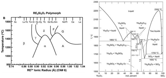
Figure 1.
Stability diagram of the various RE2Si2O7 pyrosilicate polymorphs [37] (on the left) and phase diagram of the Yb2O3–SiO2 system [39].
Ytterbium disilicate has the great advantage of inherent phase stability up to the melting point and good chemical and mechanical compatibility with SiCf/SiC and Si substrate [40]; thus, in this work, it has been selected and investigated as a candidate for an EBC system. Rare-earth monosilicates are more stable at high temperature when exposed to water vapor thanks to their higher resistance to the formation of volatile products. However, the high CTE mismatch between RE2SiO5 and the substrate leads to crack formation when exposed to high temperature, allowing for the diffusion of oxygen and water vapor throughout the coating. RE2SiO5 can crystallize in two monoclinic polymorphs depending on the ionic radius of the rare-earth element (RE3+): the X1 phase is characteristic of RE elements with a higher ion radius and thus for lanthanides from Gd to La, while the X2 phase is the crystal structure typical of RE with a lower ion radius (from Lu to Dy). RE2SiO5 compounds based on Tb and Y can crystallize in both phases, depending on the crystallization temperature: X1 for lower temperature, and X2 for higher temperature [34,41,42]. The presence of a single stable phase in the temperature range of interest is an interesting property that facilitates the avoidance of volumetric variation due to polymorphism. The architecture of coatings investigated in this work was designed considering the features and the behavior of previously mentioned silicate materials when exposed to harsh environments. In this experimentation, a multi-layer coating was designed and manufactured with three different layers with specific protective functions: (i) a Si-based bond coat whose function is to protect the substrate from oxidation and improve the adhesion of the upper layer to the SiC substrate; (ii) an intermediate layer made of ytterbium disilicates (Yb2Si2O7), which improves the thermomechanical compatibility and reduces the volatilization of Si-based compounds; (iii) a top coat based on ytterbium monosilicates (Yb2SiO5) increasing the thermal insulation and improving high-temperature stability in the presence of water vapor and resistance to CMAS attack (mixtures of CaO–MgO–Al2O3–SiO2).
EBC multilayer coatings were deposited by using the atmospheric plasma spray technique (APS), which is already widely chosen for the deposition of thermal barrier coating systems. This strategy is of great interest, because it allows for the manufacturing of EBC employing facilities already used for thermal barrier coatings with considerable costs saving.
Numerous research works have studied ytterbium monosilicate and disilicate as protective layers for EBC [17,24,40,43,44,45,46], but only some studies have presented the possibility of obtaining a tri-layer coating using Yb2Si2O7/Yb2SiO5/Si [47,48,49]; Xin et al. [50] presented a work in which this tri-layer coating is deposited via APS. In the present research, the multilayer coating Yb2Si2O7/Yb2SiO5/Si was deposited by using APS with three different torch powers, and the influence of the deposition parameters on the coating properties was deepened. In particular, crack density was deeply analyzed because it can compromise the in-service performances and durability of coatings, leading to a decay in thermal and thermomechanical performances [51]. Moreover, through-the-thickness cracks in the outer layer of the system provide a channel of access for oxidative and corrosive substances coming from combustion environments, like oxygen, water vapor, and corrosive impurities from fuel, thus reducing the durability of protective coatings. Thus, it is of great importance to carefully optimize the APS deposition parameters in order to reduce the presence of these defects, which have negative influences on the performances of these systems. Furthermore, the porosity and the chemical composition of the coatings were also studied. In fact, the presence of high porosity can facilitate the coalescence of cracks and the failure of the coating. The APS process produced thermal-sprayed coatings with a chemical composition different from the initial powders, and it is important to understand the evolution of the compounds in the final coatings.
2. Materials and Methods
Powders of the raw materials suitable for the atmospheric plasma spray technology were provided by several suppliers: silicon powders (particle size: 75/20 µm) were supplied by H.C. Starck (Goslare, Germany), while fused and crashed powders of Yb2Si2O7 (d50 = 35.4 µm) and Yb2SiO5 (d50 = 34.9 µm) were provided by Treibacher Industrie AG (Althofen, Austria).
The deposited and investigated EBC architecture is a tri-layer coating, with silicon as the bond coat, Yb2Si2O7 as the intermediate layer (YbDS), and Yb2SiO5 as the upper layer (YbMS), deposited onto sintered silicon carbide (SiC) substrates provided by IPS Ceramics (Newcastle-under-Lyme, UK). SiC substrates are considered adequate for this study because they guarantee the same chemical compatibility as, and a similar CTE to, a SiC/SiC CMC substrate. The deposition process was carried out by Borga Meccanica S.R.L. located in Chiarano (TV), Italy, using an atmospheric plasma spray (APS) (Oerlicon Metco, Wohlen, Switzerland) technique in a facility equipped with an F4-MB torch (Oerlikon Metco, Wohlen, Switzerland).
Substrates were grit blasted using 60 µm SiC grit provided by Florence Abrasives & Tools s.r.l. (Florence, Italy); then, they were cleaned in an ultrasonic bath with ethanol to remove surface contamination and improve the mechanical anchorage of the coating.
Thermal spray parameters deeply affect the composition, microstructure, and defects of the coating layers: in the present work, starting from the literature [14,24,43,46,51,52,53,54], an experimental array was developed with three different torch powers. For each layer (Si, YbDS and YbMS), the feeding rate (40 g/s) and the number of spraying passes (10) were kept constant and then arranged to obtain the desired thickness. A processing issue for silicate EBCs is the deposition of stoichiometric coatings, since during the spraying process, there is a preferential volatilization of SiO2 from molten particles; thus, Si-depleted coatings are obtained when compared with the starting powders. Obviously, the higher the temperatures and/or the longer the exposure times of the particles, the more intense is the effect of SiO2 volatilization. For this reason, coatings obtained using APS show different microstructures, compositions and porosities depending on the process parameters [52]. Furthermore, RE silicates form an undesired amorphous phase at solidification temperatures lower than 1000–1200 °C [14,24,35,52].
For this reason, the multi-layer coatings were deposited by heating substrates with the plasma plume: a special pre-heating program was used in order to reach a temperature of approximately 950–1050 °C. During this process, the temperature of the samples was monitored using a K-type thermocouple placed below the substrates.
In order to obtain high-performance coatings, the deposition process required an optimization of the thermal spray parameters: torch power, stand-off distance and strategy of deposition.
The power of the torch can be adjusted according to the current intensity, the voltage, and the gases’ flow rate. An increase in torch power can also lead to an increase in the plasma plume’s velocity, with a consequent reduction in the particles’ residence time in the plasma [55]. The variations in temperature and in the plasma plume’s velocity in turn affect the heating rate of the particles and, in the case of silicates, can also influence the evaporation of SiO2.
For this experimentation, the primary plasma gas (Ar) flow rate and current intensity of the torch were taken as constant, while three different torch powers were set, varying the secondary plasma gas, H2. The stand-off distance was kept constant and equal to 135 mm for the silicate layers. In Table 1, the matrix of the deposition parameters adopted for each material is reported.

Table 1.
Experimental array for Si/YbDS/YbMS layer deposition.
The Si bond coat was sprayed with a torch power of 25 kW and a stand-off distance of 100 mm: these parameters allow for the deposition of ~150 μm of Si with good cohesion. This bond coat was then deposited on all the SiC substrates. The silicate layers were first deposited with 10 passes. Then, according to the different thickness per pass (Table 1), a number of passes was selected to obtain thicknesses of approximately 150 μm.
YbDS layers deposited with a torch power of 16, 20, and 25 kW were denominated DS-16, DS-20, DS-25, respectively, and, in the same way, YbMS layers deposited with a torch power of 16, 20, and 25 kW were denominated MS-16, MS-20, MS-25, respectively.
EBC samples were mounted in resin and polished in order to be observed with a scanning electron microscope (Tescan Mira 3, Brno, Czech Republic) equipped with an EDS detector (EDAX/Ametek Inc., Pleasanton, CA, USA). BSE micrographs and EDS analyses allowed observation of the microstructure and phase distribution inside the silicate layers. Porosity was measured by observing samples with an optical microscope (Nikon Eclipse L150) and using the image analysis software LUCIA Measurements (v. 4.80 Laboratory Imaging S.r.o. Praha, Czech Republic). XRD analyses were performed by using a Philips X’Pert X-ray device (PANalytical B.V., Almelo, The Netherlands), operating at 40 KV and 40 mA with CuKα1 radiation. The samples were scanned with a scan range of 20°–80°, a step size of 0.02°, and a counting time of 2 s.
Crack analysis was performed using an appropriately developed image processing and analysis MATLAB routine. First, the region of interest (ROI) is selected from the original SEM picture (Figure 2a). The selected ROI is made binary according to a proper color threshold in the greyscale. This step allows the identification of cracks and porosities, which turn black and are easily distinguished from the rest of the layer under analysis, which is represented in white (Figure 2b). The image is then processed to differentiate porosities from cracks, according to their shape: porosities are removed and considered as white background so that only cracks in black are left for analysis (Figure 2c). By means of manual selection of their apex, cracks are identified (red lines in Figure 2d) and their length is calculated. The routine output is reported in Figure 2e, where red lines corresponding to cracks are superimposed on the original SEM picture, in order to prove effective matching. Several parameters can be calculated from the image processing and analysis process: the number of cracks; their mean length (1); crack density (2); overall specific crack length (3).
where A is the surface area of the analyzed coating cross-section, n is the total number of cracks, and Li is the length of each identified crack.
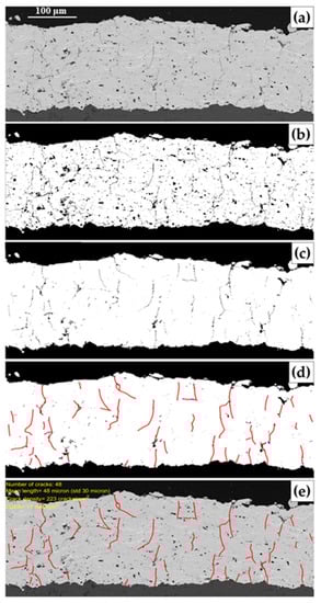
Figure 2.
Representation of the main steps involved in the image processing routine for crack analysis: (a) ROI selected on the original SEM micrograph; (b) binarized image where black regions within the coating (in white) represent cracks and porosities; (c) result of the filtering on aspect ratio, which removed porosities; (d) cracks identification (red lines); (e) routine output with the identified and analyzed cracks superimposed on the original SEM micrograph, to demonstrate the good matching.
3. Results
3.1. Microstructural Characterization: SEM Micrographs and EDS Analysis
The raw materials were characterized by performing scanning electron microscopy (FE-SEM Tescan Mira-3) and energy dispersive X-ray spectrometry (EDS) to evaluate their morphology and their composition. Then, X-ray diffraction (XRD) (Philips X’Pert X-ray device (PANalytical B.V., The Netherlands)) analyses were performed to determine their phase composition. Yb2Si2O7 powders have impurities of silicon (Figure 3a), while Yb2SiO5 ones have impurities of silicon and Yb2O3 (Figure 3b). However, these compounds were not detected by XRD measurements in ytterbium disilicate powders; the spectrum presents only diffraction peaks belonging to monoclinic Yb2Si2O7 (C2/m, 25–1345) (Figure 3c). By contrast, the XRD analysis for the ytterbium monosilicate powders shows the presence of monoclinic Yb2SiO5 (I2/a, 40–0386) and of SiO2 and Yb2O3, which are residue precursors for the formation of ytterbium monosilicate (Figure 3d). Si was identified by the SEM micrographs, but it was not detected by XRD analysis, probably because it was in an amorphous state.
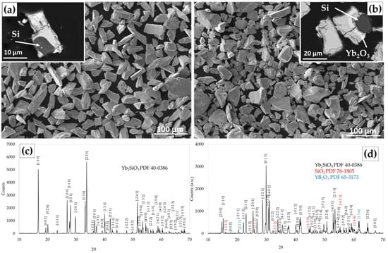
Figure 3.
SE/BSE micrographs of raw material powders (YbDS (a) and YbMS (b)), and XRD spectra (YbDS (c) and YbMS (d)).
All the deposited samples were characterized by using SEM and EDS analysis in order to observe their microstructure and to assess the composition and distribution of the different phases in the coatings. As a first step, only the YbDS coatings were deposited in order for us to understand the deposition efficiency for each program and adjust the number of passes required to obtain a comparable thickness. These coatings were also used for the XRD analysis. Then, the multi-layer coatings (YbDS and YbMS) were deposited.
Figure 4 shows the cross-section of the YbDS coatings deposited with a stand-off distance of 135 mm and different torch powers. The comparison of Figure 4a,c,e shows the lower deposition efficiency for sample DS-16, while the higher magnification micrographs in Figure 4b,d,f show the difference in the cracks’ morphology: cracks are wider in sample DS-20 and lighter in sample DS-16. In these samples, areas having different gray contrast were investigated using EDS (Figure 5): as discussed in several studies [24,52,56], dark splats have a composition closer to the powder feedstock, while bright splats show a lower Si content. This observation confirms an expected phenomenon: during the deposition process, the SiO2 partially volatilizes, and its depletion promotes, according to the phase diagram (Figure 1), the formation of Yb2SiO5. Furthermore, the observation of the BSE micrographs lightened the appearance of several shades of gray. These variations are related to the presence of splats with different amounts of very finely dispersed Yb2Si2O7 and Yb2SiO5 phases, as already observed in other studies [14,24,40,56].
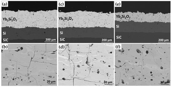
Figure 4.
Cross-section BSE micrographs of YbDS coatings: DS-25 (a,b), DS-20 (c,d), and DS-16 (e,f).
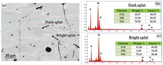
Figure 5.
BSE micrograph (a) and EDS analysis (b,c) of sample DS-25.
The quantity of volatilized SiO2 influences the composition of the final coating; for this reason, EDS quantitative analyses were carried out considering the atomic content of Yb and Si and calculating the ratio Si/(Si + Yb). The EDS analyses were carried out on areas of approximately 100 × 400 μm: for each coating, 10 areas were evaluated along all the sample, and then, the average values and the standard deviation were calculated. The results are reassumed in the histograms of Figure 6: the content of Si is very similar for the three YbDS coatings, even where it is observed that the higher the torch power is, the lower is the Si content. This means that, for YbDS, the SiO2 volatilization is more relevant for higher torch powers, and this phenomenon promotes the formation of phases with a lower Si content, like ytterbium monosilicate and ytterbium oxide. On the other hand, for YbMS, the behavior is in countertrend, so the higher the torch power, the higher the Si content.
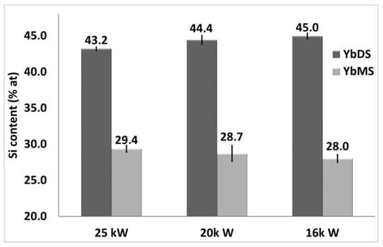
Figure 6.
Variation of Si content with respect to the torch power evaluated using EDS analysis for YbDS and YbMS layers.
In Figure 7a,c,e, several BSE micrographs show the cross-section of multilayer coatings with YbMS as the top layer, YbDS as the interlayer, and Si as the bond coat. The adhesion between layers is always good, even if some through-the-thickness cracks can be detected in the YbMS layer. BSE micrographs at higher magnification (Figure 7b,d,f) show that some cracks propagate from the YbMS layer into the YbDS layer, splitting into two horizontal cracks. In sample MS-20 (Figure 7d), the cracks propagate partially at the interface, while in the other samples, this phenomenon is not observed, and the crack propagates inside the layers.
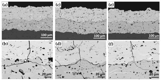
Figure 7.
Cross-section BSE micrographs of the three-layer coatings: (a,b) DS-25/MS-25, (c,d) DS-20/ MS-20, and (e,f) DS-16/MS-16.
The EDS analysis carried out on of the YbMS layers (Figure 8) shows different phases: the elements in the brighter areas are Yb and O (Si is not detected), while the elemental analysis of the darker zones suggests the presence of Yb2SiO5. In the YbMS top layer, a very small amount of Yb2Si2O7 can be detected, and also in this case, the volatilization of SiO2 during the deposition process leads to the formation of a phase with a lower amount of silicon (in this case Yb2O3).
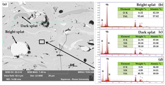
Figure 8.
BSE micrograph (a) and EDS analysis (b–d) of sample MS-16.
The histogram in Figure 6b shows the correlation of the Si atomic content with the different torch powers. The results show that in this case, an increase in the torch power leads to a higher Si content in the YbMS layer.
3.2. Microstructural Characterization: Porosity and Cracks Analysis
YbDS and YbMS coatings are affected by several defects such as porosities and cracks which need to be analyzed in order to understand the quality of the deposited coatings. All these measurements were taken on the multilayer coatings in which the YbDS is the intermediate layer and the YbMS is the top layer: this strategy is fundamental in considering the interaction between the two layers.
The histogram in Figure 9 shows that for YbDS, the higher the torch power, the lower the porosity of the coating, while for YbMS, the porosity is higher for coatings deposited with medium torch power. However, the difference among the values of porosity for the samples is almost negligible, especially observing the standard deviations.
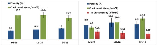
Figure 9.
Porosity, crack density, and through-the-thickness crack density for YbDS layers (on the left) and YbMS layers (on the right).
In the micrographs in Figure 4, all the YbDS layers show the presence of cracks along the entire coatings. These cracks have different morphologies and distributions: some cracks propagate from the top to the interface (through-the-thickness cracks), and others are characterized by smaller dimensions and less depth. Coatings manufactured using higher torch powers show more vertical cracks coupled with branched ones (Figure 4b,d), while those manufactured using lower torch powers have cracks with less critical size and morphology but are widespread along the entire coating layer (Figure 4f).
BSE micrographs in Figure 7 show the cross-section of the three-layer coatings with some cracks in the YbMS layer developing throughout the entire thickness. Furthermore, some vertical cracks in the YbMS layer are joined to horizontal cracks in YbDS layer (Figure 7b,d,f). As observed by Richards et al. [43], cracks in the YbMS frequently branch with a bifurcation into two cracks when they reach the YbDS layer. This phenomenon was ascribed to thermal residual stress resulting from the mismatch of coefficients of thermal expansion between the YbDS (CTE of 4.7 × 10⁻⁶ °C−1) and the YbMS (CTE of 7.5 × 10⁻⁶ °C−1) [15]. The results obtained with Matlab code for the evaluation of the crack density are summarized in Figure 9. For the DS layer, the crack density is quite similar for DS-25 and D-20, while a small decrement can be observed for samples deposited at lower power, DS-16. Several studies [57,58] have highlighted that lower plasma powers yield a lower crack density: the colder plasma jet reduces the cooling-down thermal stresses and leads to the lower volatilization of SiO2 from molten particles and thus leading to a lower crack density. For the MS layer, the results are different, and a higher crack density was measured for layers deposited with lower power. In order to better understand the crack propagation phenomena of these samples, another kind of analysis was also carried out: the density of cracks propagating for at least 70% of the coating thickness (through-the-thickness crack density or TTT crack density) was evaluated. The TTT crack density parameter was calculated as the number of TTT cracks per millimeter of coating length. In this case, sample MS-16 shows the lower value of TTT crack density (Figure 9); the higher number of micro-cracks probably allows for an efficient stress release with a consequent lower formation of TTT cracks [43].
3.3. X-ray Diffraction Analysis
The diffraction patterns belonging to the as-deposited YbDS samples DS-25, DS-20, and DS-16 are shown in Figure 10. The coatings appear partially amorphous with two broad humps at 25°–38° and 40°–70° and diffraction peaks belonging to monoclinic Yb2Si2O7 (C2/m, 25–1345). Moreover, in DS-20 and DS-16, there are peaks belonging to monoclinic Yb2SiO5 (I2/a, 40–0386). The area under the broad humps is very similar for DS-16 and DS-20, while it is higher for DS-25. This means that a higher torch power causes a higher formation of amorphous phases. Nevertheless, the wider humps corresponding to the amorphous phase in sample DS-25 can hide the effective presence of the Yb2SiO5, which shows its main characteristic peaks at 30.65° and 31.05°. This hypothesis is supported by the BSE SEM micrographs (Figure 4e,f), which show brighter areas corresponding to Yb2SiO5.
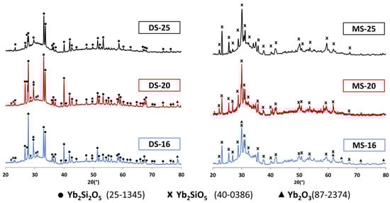
Figure 10.
XRD spectra for as-sprayed coatings (YbDS on the left and YbMS on the right).
For faster quenching, the mobility of the molecules is reduced, and they are not allowed to assume a minimum energy equilibrium position, like a lattice place; therefore, they solidify as an amorphous glass [14,59]. This is the case with samples manufactured working with higher torch powers.
In the XRD patterns of YbMS coatings (Figure 10), the two broad humps at 25°–38° and 40°–70° are totally similar to those observed in YbDS, but the area under the humps is higher compared to the YbDS spectra, showing a higher percentage of amorphous phase. The peaks correspond to monoclinic Yb2SiO5 (I2/a, 40–0386), and for MS-16, some peaks related to cubic Yb2O3 (Ia/3, 74–1981) are also detected.
4. Discussion
The presented research activity aimed to understand the influence of torch power both on the YbDS and the YbMS coatings when deposited as a multi-layer on a Si bond coat and a SiC substrate. The other deposition parameters were kept constant in order to reveal the effect of the torch power on the quality and composition of the coatings. The EDS analyses carried out on YbMS coatings show that the lower the torch power, the lower the Si content. For lower torch powers, the XRD data consistently show the formation of phases poorer in Si content, such as Yb2O3.
EDS results for YbDS coatings are different: a higher Si content is observed at lower torch power levels; at the same time, the XRD spectra show the presence of ytterbium monosilicate and ytterbium oxide only for low torch power levels (16 kW and 20 kW). This unexpected result can be due to the initial powder’s composition (for example, for YbMS, the SiO2 and Yb2O3 impurities can react during the deposition, and this phenomenon can guarantee a higher content of monosilicate) or to the reliability of the measurements (Si content is very similar for the analysed YbDS coatings). The hypothesis of a further reaction of the SiO2 and Yb2O3 during the APS process can be supported by the higher content of the powder precursor oxides (SiO2 and Yb2O3) in the YbMS, which were identified by the XRD analysis. Nevertheless, it is expected that the higher torch power causes a higher volatilization of the SiO2 because of the higher temperature of the torch plume. In any case, it is necessary to consider the velocity variation which can modify the residence time of the particles in the hottest zone of the plasma [60]. Furthermore, the SEM micrographs show that all the coatings have few unmolten particles; thus, even for the deposition program with the lower torch power, the combination of temperature and in-flight time allows for the melting of the particles [60,61]. Also, the geometry of the porosities can give important information about the thermal history of the thermal-sprayed particles: in this case, there is a prevalence of round porosities, which are due to the gas formed during the melting. By contrast, irregular porosities, due to unmolten particles, are rarely observed [61].
Porosity and crack density for YbDS and YbMS are in countertrend: for YbDS, the higher the torch power, the higher the porosity and crack density, while for YbMS, the higher the torch power, the lower the porosity and crack density. These defects can be due to poor adhesion between successively deposited layers and to the cooling-down residual stresses induced by the difference in YbDS and YbMS CTEs. It is noteworthy that for YbMS, the crack density is higher for a torch power of 16 kW, but for the same condition, the TTT crack density is lower: micro-cracking can relax the internal stress and avoid the formation of TTT cracks. SEM micrographs show that a lower torch power level leads to the formation of narrower and shorter cracks; moreover, in samples deposited at 16 kW, cracks do not propagate at the interface between YbMS and YbDS: a lower torch power seems to guarantee a better adhesion between the interlayer and the top layer. The higher torch power is more efficient only in minimizing the porosity in the YbMS and YbDS, probably because this condition can maximize the amount of molten particles during the in-flight path and their adhesion to the underneath layer.
5. Conclusions
EBC systems with a Si bond coat, an ytterbium disilicate as the interlayer, and an ytterbium monosilicate as the top coat were deposited onto SiC substrates using APS technologies with three different torch powers. The three-layer system was characterized by performing SEM/EDS analysis, and the defects, like cracks and porosities, were quantified with appropriate software. Several conclusions can be deduced:
The phenomenon of the SiO2 volatilization during the deposition process is not comparable for YbDS and YbMS, so a lower content of Si can be found in the as-sprayed YbDS for a higher torch power (DS-25), while a lower content of Si can be found in the as-sprayed Yb-MS for a lower torch power (MS-16);
The crack density is influenced by the torch power, and for YbDS, the lower the torch power, the lower the concentration of defects (DS-16), while for YbMS, a higher torch power leads to a lower crack density (MS-25). Nevertheless, the TTT crack density analysis shows that the lower torch power can also be the best solution for the YbMS layer;
The porosity is less affected by torch variation, and its minimum value is reached in both cases when the torch power is highest (DS-25, MS-25).
Author Contributions
Conceptualization, methodology and validation, G.P. (Giovanni Pulci); investigation and data curation, G.D.I., L.P. and V.G.; software, G.P. (Giulia Pedrizzetti); writing―original draft preparation, G.D.I. and L.P.; writing―review and editing, G.P. (Giovanni Pulci); supervision, F.M. and C.B. All authors have read and agreed to the published version of the manuscript.
Funding
This research received no external funding.
Institutional Review Board Statement
Not applicable.
Informed Consent Statement
Not applicable.
Data Availability Statement
The datasets generated and/or analyzed during the current study are available from the corresponding author on reasonable request.
Acknowledgments
The authors want to thank Borga Meccanica S.R.L. for the deposition of EBC coatings and technical support during the work.
Conflicts of Interest
The authors declare no conflict of interest.
References
- Aparicio, M.; Duran, A. Yttrium Silicate Coatings for Oxidation Protection of Carbon—Silicon Carbide Composites. J. Am. Ceram. Soc. 2000, 83, 1351–1355. [Google Scholar] [CrossRef]
- Kirby, G.H.; Wan, J. Compositions Containing Gallium and/or Indium and Methods of Forming the Same. U.S. Patent 10,214, 457 B2, 26 February 2019. [Google Scholar]
- Fang, G.; Gao, X.; Song, Y. A Review on Ceramic Matrix Composites and Environmental Barrier Coatings for Aero-Engine: Material Development and Failure Analysis. Coatings 2023, 13, 357. [Google Scholar] [CrossRef]
- Mehta, A.; Vasudev, H.; Singh, S.; Prakash, C.; Saxena, K.K.; Linul, E.; Buddhi, D.; Xu, J. Processing and Advancements in the Development of Thermal Barrier Coatings: A Review. Coatings 2022, 12, 1318. [Google Scholar] [CrossRef]
- Al Nasiri, N.; Patra, N.; Horlait, D.; Jayaseelan, D.D.; Lee, W.E. Thermal Properties of Rare-Earth Monosilicates for EBC on Si-Based Ceramic Composites. J. Am. Ceram. Soc. 2016, 99, 589–596. [Google Scholar] [CrossRef]
- Zhu, D. Aerospace Ceramic Materials: Thermal, Environmental Barrier Coatings and SiC/SiC Ceramic Matrix Composites for Turbine Engine Applications. NASA/TM—2018-219884. Glenn Research Center, Cleveland, Ohio. May 2018. Available online: http://www.sti.nasa.gov/ (accessed on 9 September 2023).
- Gatzen, C.; Mack, D.E.; Guillon, O.; Vaßen, R. YAlO3—A Novel Environmental Barrier Coating for Al2O3/Al2O3–Ceramic Matrix Composites. Coatings 2019, 9, 609. [Google Scholar] [CrossRef]
- Lamon, J. Chemical Vapor Infiltrated SiC/SiC Composites (CVI SiC/SiC). In Handbook of Ceramic Composites; Bansal, N.P., Ed.; Springer: Boston, MA, USA, 2005. [Google Scholar] [CrossRef]
- DiCarlo, J.A.; Yun, H.M.; Morscher, G.N.; Bhatt, R.T. SiC/SiC Composites for 1200 °C and Above. NASA/TM—2004-213048. Handbook of Ceramics Composites. 2005. Available online: http://gltrs.grc.nasa.gov (accessed on 9 September 2023).
- Corman, G.S.; Luthra, K.L. Silicon Melt Infiltrated Ceramic Composites (HiPerComp™). In Handbook of Ceramic Composites; Bansal, N.P., Ed.; Springer: Boston, MA, USA, 2005. [Google Scholar] [CrossRef]
- Ahlborg, N.L.; Zhu, D. Calcium—Magnesium aluminosilicate (CMAS) reactions and degradation mechanisms of advanced environmental barrier coatings. Surf. Coat. Technol. 2013, 237, 79–87. [Google Scholar] [CrossRef]
- Jacobson, N.S. Corrosion of Silicon-Based Ceramics in Combustion Environments. J. Am. Ceram. Soc. 1993, 76, 3–28. [Google Scholar] [CrossRef]
- Hu, W.; Zhang, J.; Nian, H.; Wang, J. Phase evolution of reactive sputtering synthesized holmium silicate coatings. J. Am. Ceram. Soc. 2018, 102, 490–497. [Google Scholar] [CrossRef]
- Bakan, E.; Marcano, D.; Zhou, D.; Jung, Y. Yb2Si2O7 Environmental Barrier Coatings Deposited by Various Thermal Spray Techniques: A Preliminary Comparative Study. J. Therm. Spray Technol. 2017, 26, 1011–1024. [Google Scholar] [CrossRef]
- Vaßen, R.; Bakan, E.; Gatzen, C.; Kim, S.; Mack, D.E.; Guillon, O. Environmental Barrier Coatings Made by Different Thermal Spray Technologies. Coatings 2019, 9, 784. [Google Scholar] [CrossRef]
- Basu, S.N.; Kulkarni, T.; Wang, H.Z.; Sarin, V.K. Functionally graded chemical vapor deposited mullite environmental barrier coatings for Si-based ceramics. J. Eur. Ceram. Soc. 2008, 28, 437–445. [Google Scholar] [CrossRef]
- Zhu, D. Advanced Environmental Barrier Coatings for SiC/SiC Ceramic Matrix Composite Turbine Components. Eng. Ceram. Curr. Status Future Prospect. 2015, 10, 187–202. [Google Scholar] [CrossRef]
- Cojocaru, C.V.; Lévesque, D.; Moreau, C.; Lima, R.S. Performance of thermally sprayed Si/mullite/BSAS environmental barrier coatings exposed to thermal cycling in water vapor environment. Surf. Coat. Technol. 2013, 216, 215–223. [Google Scholar] [CrossRef]
- Zhu, D.; Miller, R.A. Thermal and Environmental Barrier Coatings for Advanced Propulsion Engine Systems. NASA/TM—2004-213129. In Proceedings of the 60th Annual Forum and Technology Display, Baltimore, MD, USA, 7–10 June 2004. [Google Scholar]
- Gardiner, G. Commercialization of CMCs and Developments for Next-Gen Performance. CompositesWorld. 2017. Available online: https://www.compositesworld.com/articles/the-next-generation-of-ceramic-matrix-composites (accessed on 9 September 2023).
- Wang, P.; Liu, F.; Wang, H.; Li, H.; Gou, Y. A review of third generation SiC fibers and SiCf/SiC composites. J. Mater. Sci. Technol. 2019, 35, 2743–2750. [Google Scholar] [CrossRef]
- Xu, Y.; Hu, X.; Xu, F.; Li, K. Rare earth silicate environmental barrier coatings: Present status and prospective. Ceram. Int. 2017, 43, 5847–5855. [Google Scholar] [CrossRef]
- Lee, K.N. Current status of environmental barrier coatings for Si-Based ceramics. Surf. Coat. Technol. 2000, 133, 1–7. [Google Scholar] [CrossRef]
- Richards, B.T.; Wadley, H.N.G. Plasma spray deposition of tri-layer environmental barrier coatings. J. Eur. Ceram. Soc. 2014, 34, 3069–3083. [Google Scholar] [CrossRef]
- Withey, E.; Petorak, C.; Trice, R.; Dickinson, G.; Taylor, T. Design of 7 wt.% Y2O3—ZrO2/mullite plasma-sprayed composite coatings for increased creep resistance. J. Eur. Ceram. Soc. 2007, 27, 4675–4683. [Google Scholar] [CrossRef]
- Lee, K.N.; Fox, D.S.; Bansal, N.P. Rare earth silicate environmental barrier coatings for SiC/SiC composites and Si3N4 ceramics. J. Eur. Ceram. Soc. 2005, 25, 1705–1715. [Google Scholar] [CrossRef]
- Tejero-Martin, D.; Bennett, C.; Hussain, T. A review on environmental barrier coatings: History, current state of the art and future developments. J. Eur. Ceram. Soc. 2021, 41, 1747–1768. [Google Scholar] [CrossRef]
- Lee, K.N.; Miller, R.A.; Jacobson, N.S.; Opila, E.J. Environmental durability of mullite coating/SiC and mullite-YSZ coating/SiC systems. Ceram. Eng. Sci. Proc. 1995, 1037–1044. [Google Scholar] [CrossRef]
- Lee, K.N.; Fox, D.S.; Eldridge, J.I.; Zhu, D.; Robinson, R.C.; Bansal, N.P.; Miller, R.A. Upper Temperature Limit of Environmental Barrier Coatings Based on Mullite and BSAS. J. Am. Ceram. Soc. 2003, 8, 1299–1306. [Google Scholar] [CrossRef]
- Lee, K.N.; Eldridge, J.I.; Robinson, R.C. Residual Stresses and Their Effects on the Durability of Environmental Barrier Coatings for SiC Ceramics. J. Am. Ceram. Soc. 2005, 88, 3483–3488. [Google Scholar] [CrossRef]
- Lee, K.N.; Fox, D.S.; Robinson, R.C.; Bansal, N.P. Environmental Coatings for Silicon-Based Ceramics. In Proceedings of the 4th High Temperature Ceramic Matrix Composites Conference, Munich, Germany, 1–3 January 2001. [Google Scholar]
- Sarkisov, P.D.; Popovich, N.V.; Orlova, L.A.; Anan’eva, Y.E. Barrier coatings for type C/SiC Ceramic Matrix Composites (Review). Glas. Ceram. 2008, 65, 44–49. [Google Scholar] [CrossRef]
- Wang, Y.; Liu, J. First-principles investigation on the corrosion resistance of rare earth disilicates in water vapor. J. Eur. Ceram. Soc. 2009, 29, 2163–2167. [Google Scholar] [CrossRef]
- Felsche, J. The Crystal Chemistry of the Rare-Earth Silicates. In Rare Earths. Structure and Bonding; Springer: Berlin/Heidelberg, Germany, 1973; Volume 13, pp. 99–197. [Google Scholar] [CrossRef]
- Richards, B.T.; Young, K.A.; De Francqueville, F.; Sehr, S.; Begley, M.R.; Wadley, H.N.G. Response of ytterbium disilicate-silicon environmental barrier coatings to thermal cycling in water vapor. Acta Mater. 2016, 106, 1–14. [Google Scholar] [CrossRef]
- Tian, Z.; Zhang, J.; Zhang, T.; Ren, X.; Hu, W.; Zheng, L. Towards thermal barrier coating application for rare earth silicates RE2SiO5 (RE = La, Nd, Sm, Eu, and Gd). J. Eur. Ceram. Soc. 2019, 39, 1463–1476. [Google Scholar] [CrossRef]
- Turcer, L.R.; Padture, N.P. Towards multifunctional thermal environmental barrier coatings (TEBCs) based on rare-earth pyrosilicate solid-solution ceramics. Scr. Mater. 2018, 154, 111–117. [Google Scholar] [CrossRef]
- Felsche, J. Polymorphism and crystal data of the rare-earth disilicates of type RE2Si2O7. J. Less-Common Met. 1970, 21, 1–14. [Google Scholar] [CrossRef]
- Costa, G.C.C.; Jacobson, N.S. Mass spectrometric measurements of the silica activity in the Yb2O3–SiO2 system and implications to assess the degradation of silicate-based coatings in combustion environments. J. Eur. Ceram. Soc. 2015, 35, 4259–4267. [Google Scholar] [CrossRef]
- Garcia, E.; Garces, H.F.; Turcer, L.R.; Bale, H.; Padture, N.P.; Sampath, S. Crystallization behavior of air-plasma-sprayed ytterbium-silicate-based environmental barrier coatings. J. Eur. Ceram. Soc. 2021, 41, 3696–3705. [Google Scholar] [CrossRef]
- Tian, Z.; Zheng, L.; Wang, J.; Wan, P.; Li, J.; Wang, J. Theoretical and experimental determination of the major thermo-mechanical properties of RE2SiO5 (RE = Tb, Dy, Ho, Er, Tm, Yb, Lu and Y) for environmental and thermal barrier coating applications. J. Eur. Ceram. Soc. 2016, 36, 189–202. [Google Scholar] [CrossRef]
- Ricci, P.C.; Carbonaro, C.M.; Corpino, R.; Cannas, C.; Salis, M. Optical and Structural Characterization of Terbium-Doped Y2SiO5 Phosphor Particles. J. Phys. Chem. 2011, 115, 16630–16636. [Google Scholar] [CrossRef]
- Richards, B.T.; Sehr, S.; De Franqueville, F.; Begley, M.R.; Wadley, H.N.G. Fracture mechanisms of ytterbium monosilicate environmental barrier coatings during cyclic thermal exposure. Acta Mater. 2016, 103, 448–460. [Google Scholar] [CrossRef]
- Zhong, X.; Niu, Y.; Li, H.; Zhu, T.; Song, X.; Zeng, Y. Comparative study on high-temperature performance and thermal shock behavior of plasma-sprayed Yb2SiO5 and Yb2Si2O7 coatings. Surf. Coat. Technol. 2018, 349, 636–646. [Google Scholar] [CrossRef]
- Lee, K.N.; Zhu, D.; Lima, R.S. Perspectives on Environmental Barrier Coatings (EBCs) Manufactured via Air Plasma Spray (APS) on Ceramic Matrix Composites (CMCs): A Tutorial Paper. J. Therm. Spray Technol. 2021, 30, 40–58. [Google Scholar] [CrossRef]
- Jian, Y.; Wang, Y.; Liu, R.; Wan, F.; Zhang, J. Property evolutions of Si/mixed Yb2Si2O7 and Yb2SiO5 environmental barrier coatings completely wrapping up SiCf/SiC composites under 1300 °C water vapor corrosion. Ceram. Int. 2021, 47, 22373–22381. [Google Scholar] [CrossRef]
- Poerschke, L.; Hass, D.D.; Eustis, S.; Seward, G.G.E.; Van Sluytman, J.S.; Levi, C.G. Stability and CMAS Resistance of Ytterbium-Silicate/Hafnate EBCs/TBC for SiC Composites. J. Am. Ceram. Soc. 2015, 98, 278–286. [Google Scholar] [CrossRef]
- Kawai, E.; Kakisawa, H.; Kubo, A.; Yamaguchi, N.; Yokoi, T.; Akatsu, T.; Kitaoka, S.; Umeno, Y. Crack Initiation Criteria in EBC under Thermal Stress. Coatings 2019, 9, 697. [Google Scholar] [CrossRef]
- Anton, R.; Leisner, V.; Laska, N.; Schulz, U. Reactive Sputtered Ytterbium Silicate Environmental Barrier Coatings for Protection of Mo-Si-Based Alloys. Coatings 2022, 12, 1086. [Google Scholar] [CrossRef]
- Zhong, X.; Niu, Y.; Li, H.; Zhou, H.; Dong, S.; Zheng, X.; Ding, C.; Sun, J. Thermal shock resistance of tri-layer Yb2SiO5/Yb2Si2O7/Si coating for SiC and SiC-matrix composites. J. Am. Ceram. Soc. 2018, 101, 4743–4752. [Google Scholar] [CrossRef]
- Xiao, J.; Liu, Q.; Li, J.; Guo, H.; Xu, H. Microstructure and high-temperature oxidation behavior of plasma-sprayed Si/Yb2SiO5 environmental barrier coatings. Chin. J. Aeronaut. 2019, 32, 1994–1999. [Google Scholar] [CrossRef]
- Richards, B.T.; Zhao, H.; Wadley, H.N.G. Structure, composition, and defect control during plasma spray deposition of ytterbium silicate coatings. J. Mater. Sci. 2015, 50, 7939–7957. [Google Scholar] [CrossRef]
- Wang, H.; Zhang, J.; Sun, L.; Wang, J. Microstructure and phase composition evolution of dual-phase ytterbium silicate coatings plasma sprayed from stoichiometric Yb2Si2O7 feedstock powder. Surf. Coat. Technol. 2022, 437, 128373. [Google Scholar] [CrossRef]
- Han, J.; Wang, Y.; Liu, R.; Cao, Y. Thermal shock behavior of mixed ytterbium disilicates and ytterbium monosilicates composite environmental barrier coatings. Surf. Coat. Technol. 2018, 352, 348–353. [Google Scholar] [CrossRef]
- Vardelle, M.; Vardelle, A.; Fauchais, P. Spray Parameters and Particle Behavior Relationships During Plasma Spraying. ASM Int. 1993, 2, 79–91. [Google Scholar] [CrossRef]
- Garcia, E.; Sotelo-Mazon, O.; Poblano-Salas, C.A.; Trapaga, G.; Sampath, S. Characterization of Yb2Si2O7–Yb2SiO5 composite environmental barrier coatings resultant from in situ plasma spray processing. Ceram. Int. 2020, 46, 21328–21335. [Google Scholar] [CrossRef]
- Ito, K.; Kuriki, H.; Araki, H.; Kuroda, S.; Enoki, M. Detection of segmentation cracks in top coat of thermal barrier coatings during plasma spraying by non-contact acoustic emission method. Sci. Technol. Adv. Mater. 2014, 15, 1–11. [Google Scholar] [CrossRef]
- Taniguchi, K.; Enoki, M. In situ monitoring of cracking behaviors of plasma-sprayed coatings by the laser acoustic emission technique. Mater. Res. Soc. 2009, 24, 3182–3189. [Google Scholar] [CrossRef]
- Huelsenberg, D.; Harnisch, A.; Bismarck, A. Microstructuring Glasses Using Lasers. In Microstructuring of Glasses; Springer Series in Materials Science; Springer: Berlin/Heidelberg, Germany, 2008; Volume 87. [Google Scholar] [CrossRef]
- Jarligo, M.O.; Mack, D.E.; Mauer, G.; Vaßen, R.; Stover, D. Atmospheric Plasma Spraying of High Melting Temperature Complex Perovskites for TBC Application. J. Therm. Spray Technol. 2010, 9, 303. [Google Scholar] [CrossRef]
- Zhu, T.; Niu, Y.; Zhong, X.; Zhao, J.; Li, Q.; Zeng, Y.; Zheng, X. Influence of phase composition on thermal aging behavior of plasma sprayed ytterbium silicate coatings. Ceram. Int. 2018, 44, 17359–17368. [Google Scholar] [CrossRef]
Disclaimer/Publisher’s Note: The statements, opinions and data contained in all publications are solely those of the individual author(s) and contributor(s) and not of MDPI and/or the editor(s). MDPI and/or the editor(s) disclaim responsibility for any injury to people or property resulting from any ideas, methods, instructions or products referred to in the content. |
© 2023 by the authors. Licensee MDPI, Basel, Switzerland. This article is an open access article distributed under the terms and conditions of the Creative Commons Attribution (CC BY) license (https://creativecommons.org/licenses/by/4.0/).