Abstract
Laser-induced periodic surface structures (LIPSS) enable advanced surface functionalization with broad applications in various fields such as micro- and nanoelectronics, medicine, microbiology, tribology, anti-icing systems, and more. This study demonstrates the possibility of achieving anisotropy in the tribological behavior of C45-grade steel structured by nanosecond laser radiation using the LIPSS method. The lateral surface of the steel roller was irradiated with a pulsed Nd:YAG laser at an optimum intensity I = 870 MW/cm2 for the formation of LIPSS. Two sets of samples were formed with LIPSS that were perpendicular and parallel to the roller’s rotational motion direction. The Raman intensity maps revealed that the LIPSS structure consisted of periodically arranged oxides at the top of hills. At the same time, the valleys of the LIPSS structures were almost not oxidized. These results correlated well with scanning electron microscopy energy dispersive X-ray spectroscopy mapping and atomic force microscopy measurements. A comparison of Raman and X-ray photoelectron spectroscopy spectra revealed that both the magnetite phase and traces of the hematite phase were present on the surface of the samples. Tribological tests were performed in two cycles with periodic changes in the normal clamping force and sliding speed. It was found that the LIPSS structures which were formed perpendicularly to the sliding direction on the roller had a significantly greater impact on the friction processes. Structures oriented perpendicular to the direction of motion had a positive influence on reducing the energy consumption of a friction process as well as increasing the wear resistance compared to LIPSS formed parallel to the direction of motion or ones having a non-texturized surface. Laser texturing to produce LIPSS perpendicular to the direction of motion could be recommended for friction pairs operating under low-load conditions.
1. Introduction
Laser texturing is a method which involves the remelting or removal of material from a surface to create more durable and shear-resistant textures compared to other methods that supplement the material to the surface [1]. Recently, laser texturing has also focused on cold region applications such as the development of ice-phobic surfaces for road signs, wind turbine blades, building constructions, airplane constructions, etc., preventing ice build-ups on them [2,3,4,5,6]. Laser-induced surface texturing has many advantages, such as its flexibility, high-speed texturing, well-controlled surface characteristics, applicability for the metal industry, and being environmentally friendly [7,8].
Among the techniques that can be used for patterning surfaces is the formation of laser-induced periodic surface structures (LIPSS, also known as ripples) using a laser beam with linearly polarized radiation [6,9,10]. LIPSS can be classified by their spatial frequency: low spatial frequency LIPSS (LSFL) and high spatial frequency LIPSS (HSFL). In the first case, the period Λ of the LSFL is of the order of the used laser wavelength (Λ~λ) and its orientation is perpendicular to the pulse polarization [11]. In the second case, the period Λ of the HSFL is much smaller than that of the laser wavelength Λ << λ and is generated with an orientation parallel to that of the light polarization [12]. The LIPSS technique can be applied to almost any material, including metals [13], semiconductors [14], superconductors [15], polymers [16,17], dielectrics [18], or 2D nanomaterials [19].
The mechanism of the LIPSS formation remains the subject of debate, and generally, it can be divided into two kind of theories according to the materials and laser parameters: (1) electromagnetic theories which describe the deposition of the optical energy into the solid; (2) matter reorganization theories, which are based on the redistribution of matter at the surface layer [20,21]. One of the most widely accepted mechanisms for the formation of LSFL structures is the action of surface plasmon polaritons on rough metal surfaces [22]. The initial roughness of the material is crucial for producing scattering which may lead to the generation of surface plasmon polaritons that interfere with the incident light and modulate the finally absorbed fluence “imprints” in the material, while selectively ablating the parallel periodic structures [6].
Numerous studies have revealed an increase in friction using LIPSS fabricated through ultra-short pulse laser processing on various substrate materials [23]. Nevertheless, the formation of LIPSS in environmental atmosphere or specific gas atmosphere has an influence not only on structured material topography, wettability [2,3,4,5,7,24,25], and tribological properties [2,4,23], but also on its chemical properties [10,26]. There are long-lasting debates in the LIPSS community regarding the input of topography and surface chemistry for surface functionalization [10]. Side effects such as metal oxidation processes at higher laser intensities could take place during the laser irradiation of metals in an air environment [26,27]. The resulting superficial oxide layer would play an important role in tribological performances [28,29].
Recent publications have shown that a laser-induced oxide layer led to a reduction in friction and wear resistance [28,30]. Bonse et al. [29] studied the chemical effects and tribological performances of a titanium alloy (Ti6Al4V) while forming various types of femtosecond-laser-generated surface structures, such as LIPSS, grooves, and spikes. However, changes in the friction coefficient for LIPSS in both sliding directions for a 1 N load applied on the ball in linear motion have not been revealed. Nevertheless, anisotropic micro-texturing has previously been used for friction control depending on the direction [1]. Gachot et al. [31,32,33] studied dry friction of stainless steel surfaces patterned in a micro-length scale obtained with laser irradiation. The study showed that the use of direct laser interference patterning (DLIP) structures reduced the coefficient of friction after running-in. Zhang and Kyriakos [34] conducted a study highlighting the properties of nanoscale ripples obtained by oblique Ar+ ion beam irradiation on silicon surfaces. Their research revealed that these ripples exhibit scale-dependent nanomechanical behavior and display anisotropic friction characteristics. The team provided insightful explanations for the observed experimental trends by delving into the underlying physical mechanisms governing deformation behavior during indentation loading and considering the impact of adhesion forces at the sliding contact interface on the overall frictional forces. This research sheds light on the intricate nature of nanoscale systems and contributes to our understanding of surface engineering and nanotribology.
In this study, we demonstrated the attainment of anisotropic tribological behavior in a liquid lubricant medium for C45-grade steel through the implementation of nanosecond laser radiation and the LIPSS method. The primary objective of our investigation was to gain insights into the effects of normal load and sliding speed on frictional losses and wear resistance, with a particular emphasis on understanding these influences in relation to the direction of the LIPSS. We analyzed these parameters to understand the interplay between surface structuring, tribological performance, and the resulting wear characteristics. The findings of this study contribute to the broader field of surface engineering and provide valuable information for enhancing the design and performance of lubricated systems.
2. Materials and Methods
2.1. Sample Preparation and Laser Processing
Hollow cylinders (rollers) made of C45-grade steel (HRC 40–43), consisting of 0.45% C, 0.4% Si, 0.6% Mn, 0.02% P, 0.03% S, and Fe, were mechanically polished with diamond paste followed by a GOI polishing paste to obtain a mirror-like surface with an average roughness value of 29 nm. The samples were washed in isopropyl alcohol in an ultrasonic bath and dried under dry airflow.
The lateral surface of a cylinder with an outer diameter Øo = 35 mm and inner diameter ØI = 16 mm was irradiated in air with a flash-lamp pumped Q-switched pulsed Nd:YAG laser model NL301G, produced by Ekspla (Lithuania) with the following parameters: wavelength of the laser λ = 1064 nm; laser pulse intensity I = 870 MW/cm2 (no changes to structural properties were observed at a laser intensity lower than 870 MW/cm2), pulse duration τ = 6 ns, repetition rate of ν = 10 Hz, beam profile “Hat-Top” [35], and beam diameter of Ø = 0.5 mm. A hatch spacing of 0.4 mm was used and the rotating speed of the cylinder was 1.0 mm/s. The irradiation of the samples was carried out in an air environment at room temperature and ambient pressure.
2.2. Samples Characterisation Prior to Friction and Wear Tests
The surfaces of the samples were analyzed by atomic force microscopy (AFM) with a Smena (NT-MDT) instrument in semi-contact mode using a golden silicone probe NSG03 (NT-MDT) to characterize the surface roughness and topography of the samples. Areas of 15 × 15 µm in size were scanned by AFM using a scan velocity of 12 µm/s and step size of 78 nm.
A field emission scanning electron microscope (FE-SEM) Zeiss Auriga Crossbeam and energy dispersive X-ray (EDX) analysis detector were used to characterize the surface structures and perform chemical analyses through elemental mapping.
Micro-Raman shift measurements and mapping were carried out with a Renishaw In-ViaV727 spectrometer with a backscattering geometry at room temperature. The phonon excitation was induced with a green laser (Ar+, λ = 514.5 nm, grating–1200 mm−1), the exposure time for one accumulation was 3 s, and each spectrum consisted of three accumulations. The integral sum of the Raman spectrum intensity from 77 to 1000 cm−1 was used to create a Raman map (with a spatial lateral resolution of 0.25 µm and axial resolution <1 µm) to display the changes in the chemical composition of different parts of the sample.
The effect of the surface modifications was analyzed by X-ray photoelectron spectroscopy (XPS, Escalab Xi+, Thermo Scientific, Waltham, MA, USA) with an Al K-alpha X-ray source with spatial resolution (spot size) of 500 µm, and without further surface cleaning with an ion gun. The sample was attached to the sample holder specially designed for thick samples (Thermo Scientific) using carbon tape. The advantageous carbon peak at 284.8 eV was used as a calibration point. Peak fitting was performed using the Avantage 5.9925 software.
2.3. Friction and Wear Test
The block, as a counter-body of friction tests, was made of construction C45-grade steel, and a molybdenum coating was applied with the electro spark method using an industrial EFI-10M machine (Moldova) that operated with a current intensity of 0.7–2.0 A under the conditions of an unprotected medium.
The friction and wear tests were performed on a modernized SMC-2 friction machine using the block-on-roll test (testing scheme shown in Figure 1), which corresponded to the block-on-ring test scheme of the ASTM D2714 standard.
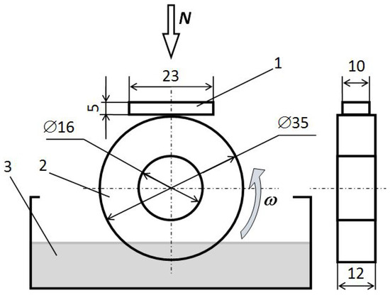
Figure 1.
Principal scheme of the block-on-roll test: 1–block; 2–cylindrical shape steel sample; 3–oil bath; N–normal load; ω–roller rotation direction.
During the tribological test, the normal load F and roller rotation speed varied in different cycles, as shown in Figure 2. In total, two test cycles were performed and the friction distance of each cycle was 20,000 m. During each cycle, the tests were performed under three different loads F of 300, 450, and 600 N, and the rollers were rotated at three different speeds of 400, 600, and 800 rpm. The tribological tests were performed in an oil bath. The test roller was partly submerged in commercial 15 W-40 mineral engine oil produced by SCT Lubricants to ensure mixed-boundary lubrication conditions. The roughness of the counter-body blocks with a molybdenum coating prepared for the tribological tests was Ra = 0.41 μm. As mentioned in Section 2.1, the working surface of the roller was mechanically polished before being irradiated with a laser.
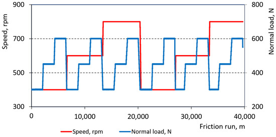
Figure 2.
Diagram of the block-on-roll test performed in two cycles of revolutions per minute (each cycle: n = 400, 600, and 800 rpm) (red line) and six cycles of load force (each cycle: F = 300, 450, and 600 N) (blue line).
Surface roughness was measured using a MahrSurf GD 25 stylus profilometer (Mahr GmbH, Goettingen, Germany) with a stylus tip with a radius of 2 µm and a measurement length of 3 mm. The wear of the segments and rollers was determined after friction tests by weighing with a ABJ 120-4 M electronic scale (Kern & Sohn GmbH, Balingen, Germany) with an accuracy of 0.1 mg.
3. Results and Discussion
3.1. Surface Morphology and Chemical Composition
The images of the obtained samples (a,b) and optical images (c,d) of LIPSS formed with the Nd:YAG laser on the ring-shaped C45-grade steel are shown in Figure 3. Due to the interference of the formed structures, one (Figure 3a) or two (Figure 3b) stripes of rainbow-like colors could be observed depending on the LIPSS direction when the samples were exposed to light [36]. The period (Λ) between such structures (Figure 3c,d) was typically close to that of the laser wavelength, which corresponded to an applied laser radiation wavelength λ = 1064 nm.
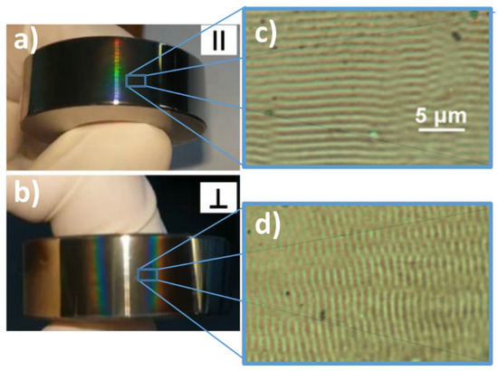
Figure 3.
The images of the cylindrical shape steel samples irradiated with a Nd:YAG laser with laser-induced surface structures parallel (∥) and perpendicular (⊥) to the direction of rotation (a,b), optical microscope images of the laser-induced periodic surface structures (LIPSS) (c,d). The scale bar of 5 μm applies to both optical images in (c,d).
The AFM study of the samples allowed us to determine more accurately the shape and surface roughness of the LIPSS prior to studying their tribological properties. The AFM scans are presented in Figure 4 for non-irradiated (a) and laser-irradiated samples with LIPSS (b,c). It can be noted that, when irradiating the sample with the Nd:YAG laser, LIPSS consisting of periodically arranged hills and valleys with a period Λ of around 1 µm were formed on the surface. As can be seen from Figure 4d line profile, the average value of the peak-to-valley-height difference was ~ 20 nm for the LIPSS structures. A slight surface polishing had occurred, which was evidenced by reduced roughness root mean square values Ra from 29 nm to 13 nm for the non-irradiated and irradiated sample, respectively.
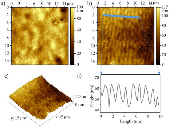
Figure 4.
Atomic force microscopy (AFM) topography imaging of the cylindrical shape C45-grade steel surface: (a) non-irradiated, (b) 2D, (c) a 3D representation, and (d) line profile of laser-induced periodic surface structures (LIPSS) obtained through irradiation with a Nd:YAG laser.
The FE-SEM image of the irradiated C45-grade steel roller sample is shown in Figure 5. A comparison of the AFM (Figure 4b) and FE-SEM (Figure 5a) images showed that the structure was typical for such experiments. However, energy dispersive X-ray (EDX) analysis mapping (Figure 5b) revealed that oxides were formed on the hills of the LIPSS rather than in the valleys. Gachot et al. [37] conducted a study on oxide formation, morphology, and nano-hardness of steel that was patterned using the DLIP (direct laser interference patterning) method. This technique involves the interference of two laser beams to create a periodic structure in the micrometer range, with a periodicity of 18 μm and a depth of 8 μm. It was found that the laser-irradiated part of the steel had an oxide layer with thickness up to 15.4 nm. Results showed a significant increase in nano-hardness, from 2.2 GPa to 3.8 GPa, for laser-irradiated samples. It is well-known that metal oxides generally exhibit higher hardness compared to their corresponding pure metal forms [38]. It was concluded that both the oxide layer and the substrate structure played a significant role in this increased hardness. Figure 5c shows an EDS map of iron atoms which were evenly distributed over the sample surface. The SEM-EDS mapping revealed that the surface with LIPSS contains significant oxygen contents of up to 24 at.%. The oxygen atoms were distributed periodically on the hills of the LIPSS with a period of ~1 µm, which corresponded to that of the laser wavelength.
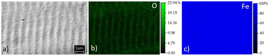
Figure 5.
Field emission scanning electron microscopy (FE-SEM) image of the C45-grade steel sample with LIPSS formed by Nd:YAG laser radiation (a) and elemental energy dispersive X-ray (EDX) analysis maps of oxygen (b) and iron (c) concentrations.
The room temperature Raman spectrum of the C45-grade steel sample with LIPSS is shown in Figure 6a. The spectrum consisted of a series of broad and weak peaks at 200 cm−1, 320 cm−1, 450 cm−1, and 540 cm−1 and one strong peak at 668 cm−1. Magnetite (Fe3O4) or hematite (Fe2O3) were formed as a result of the interaction between the Nd:YAG laser radiation and the C45-grade steel sample in air, as suggested by the possible peaks overlap [39,40]. According to [39], the modes at 193 and 538 cm−1 have a T2g symmetry, while modes at 306 and 668 cm−1 are associated with Eg and A1g ones. In comparison, the T2g mode between 450 and 500 cm−1 was almost absent. Detailed descriptions of modes in the Raman spectrum of magnetite can be found in [39,41]. The Raman intensity maps (Figure 6b) showed that the structure consisted of periodically arranged and oxidized hills and valleys, which were almost not oxidized. These findings correlate well with the SEM-EDS measurements. The Raman signal for C45-grade steel without LIPSS was weak and did not reveal any significant bands (not presented here).
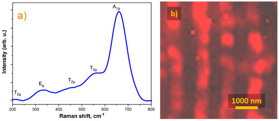
Figure 6.
Typical Raman spectrum of a Nd:YAG laser-irradiated C45-grade steel sample with LIPSS (a) and Raman mapping of periodically arranged and oxidized hills (b).
In addition to the Raman analysis, XPS measurements were carried out to identify the composition of the iron oxide phase. The XPS Fe 2p spectrum of the irradiated C45-grade steel roller sample is shown in Figure 7. The presence of both iron oxidation states could be observed. Iron peaks Fe 2p_3/2 at 710.2 eV and Fe 2p_1/2 at 723.2 eV with a peak splitting of 13 eV could be attributed to the Fe2+ oxidation state. The peaks at Fe 2p_3/2 at 711.7 eV and Fe 2p_1/2 at 72.3 eV with a peak splitting of 13.6 eV corresponded to Fe3+ oxidation states. Multiple Fe satellite signals could also be observed. The concentrations of the Fe2+ and Fe3+ oxidation states were 38.6% and 61.4%, respectively. The XPS O 1s spectra can be observed in the Figure 7b. Maximum at 530.3 eV can be assigned to the lattice oxygen (Fe3O4) [42,43]. A significant amount of surface hydroxide groups can be observed at 532.1 eV. Hydroxyl groups form the first few monolayers of surface contamination [44] and can be attributed to ambient conditions. A comparison of the Raman (Figure 6a) and XPS (Figure 7) spectra showed that a magnetite phase and traces of a hematite phase were both present on the surface of the samples. According to these analyses, it was concluded that magnetite was the dominant oxide present on the surface of the samples.
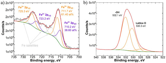
Figure 7.
X-ray photoelectron spectroscopy (XPS) Fe 2p (a) and O 1s (b) spectra for a Nd:YAG laser-irradiated C45-grade steel sample with laser-induced periodic surface structures (LIPSS).
3.2. Evaluation of Tribological Properties
The schedule of the tribological testing is presented in Figure 2. The results of the friction torque variation during the first test cycle (20.000 m) at steady test modes (speed n = 400, 600, 800 rpm; load F = 300, 450, 600 N) are provided in Figure 8.
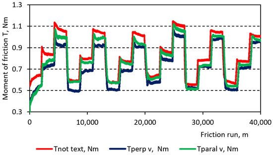
Figure 8.
Variation of the friction torque T during the tests: Tnot–surface without texture, Tperp–perpendicularly textured surface, and Tparal–parallel textured surface.
Our results revealed that the largest change in the friction torque occurred during the first stage of the test cycle (n = 400 rpm). The change in the friction torque when using the other modes was smaller during this test cycle, and in most cases, it was almost constant. However, this was exclusively due to the adaptation of the friction surfaces to each other during the initial stage of the friction pair testing. We see that in all cases, the friction pair with the non-textured surface had the highest friction torque. Table 1 shows the values of the average friction torque and energy consumed per 1 km of friction path for the different test variants. The table shows that in most cases, as the speed increased, the friction torque decreased, since an oil wedge was more readily formed when the speed increased. Conversely, as the load increased, the lubrication conditions deteriorated, and the friction torque increased.

Table 1.
Mean values of friction torque T and energy consumption E per 1 km of friction path.
The patterns of energy consumption (Table 1) showed that the reduction in the comparative energy consumption during the 1 km friction run in the first test cycle due to texturing was much higher than in the second one.
Two main factors could be distinguished when evaluating the influence of LIPSS on the energy consumption of the friction process and wear resistance of the surface: (1) an oxidized layer was formed on the surface of LIPSS hills; (2) LIPSS formed the periodic comb-striated relief on the surface of the metallic specimens. The influence of the relief on the friction and wear parameters was especially clear when the LIPSS were formed perpendicular to the direction of motion. In this case, texturing could reduce the energy consumption by up to 20% per km, which had a positive effect on the wear resistance on the whole friction pair. The wear resistance could potentially increase by more than twice compared to the friction pair with LIPSS formed parallel (∥) to the direction of motion and the untextured roller (Figure 9).
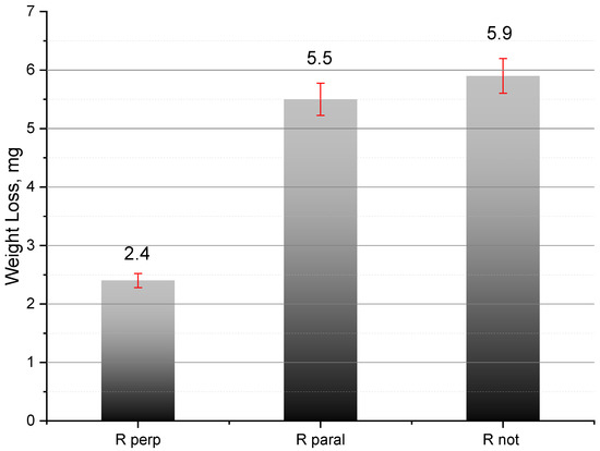
Figure 9.
Total weight loss of friction pair bodies: Rperp–roller textured perpendicular to the direction of motion, Rparal–textured parallel to the direction of motion, and Rnot–roller without textures.
As shown through the testing of laser-textured surfaces, the increase in wear resistance may have been due to the oil reservoir effect and hydrodynamic lifting effect provided by the LIPSS grooves/valleys (Figure 4d) between them which were regularly distributed in the contact zone and could act as integrated pressure pockets. These pockets could also act as traps for abrasion products, leaving a free medium between the surface of the roller and the coating [45,46]. A more continuous and durable boundary lubrication layer between the friction surfaces was provided as a result of the greater wettability of the surface and the formed grooves.
However, in the second test cycle, the texturing effect on the wear resistance was lower and reached up to 10%. This was explained by the fact that under high load conditions (450 and 600 N), the textured surface was more vulnerable to wear and therefore, the texturing effect became lower due to the wear of the texturizing structures compared to the effect obtained during the first test cycle.
Gachot et al. [33] presented a review paper stating that texturized surfaces could reduce the friction coefficient under boundary lubrication conditions only in the case of the texture being able to induce a hydrostatic force when the dimple was passed over and the normal reaction force counterbalanced the load and formed a continuous lubrication film. However, under mixed lubrication conditions, the shallow dimples and groove lines of texturized surfaces in most cases could induce hydrodynamic pressure and reduce the friction. The results of our tests showed that the surface texturized perpendicular to the sliding direction could create the conditions required for the formation of a lubrication film. The linear hills formed by LIPSS, when they were perpendicular to the sliding direction, created oil reservoirs in the valleys formed between the linear hills (also perpendicular to the sliding direction). This influenced the formation of the oil film and at the same time the lubrication mode in the friction pair. Our friction measurement results (Figure 8) showed that, when the LIPSS were perpendicular to the direction of movement, the coefficient of friction was around µ = 0.08…0.09, while for a non-textured surface µ = 0.1…0.12. The tops of LIPSS-formed hills were also strongly oxidized, as attested by the formation of a Fe3O4 layer. This surface property strengthened the boundary layer of the oil, making it more resistant to breach. Both features (formation of oil reservoirs and strengthening of the boundary oil layer due to better surface lubricity) contributed to the reduction of wear (Figure 9). Calculations of friction energy losses showed that up to 20 percent of the energy can be saved when using contact surfaces with LIPSS structures formed perpendicularly to the sliding direction. Such structures formed by precise LIPSS surface treatments could be used to produce low energy-consuming sub-micrometric textures of friction surfaces for precise components of implants, robots, and other precise elements. Such a LIPSS technology could also be used for haptic kinaesthetic communication technologies, sensory systems, etc. [23].
The Figure 10 shows FESEM images with different magnification of the non-irradiated (a,b) and laser-irradiated samples with laser-induced periodic surface structures (LIPSS) parallel (c,d) and perpendicular (e,f) to the direction of rotation after wear tests.
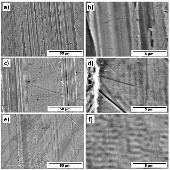
Figure 10.
FESEM images of the non-irradiated samples (a,b) and the laser-irradiated samples with laser-induced periodic surface structures (LIPSS) parallel (c,d) and perpendicular (e,f) to the direction of rotation after wear tests.
The surface that was most affected was untextured (a,b). The surface textured parallel (c,d) and perpendicular (e,f) to the direction of movement was also damaged during the tests, but the damage is smaller compared to the non-textured surface (a,b). In all cases abrasion wear with comparably deep scratches is the prevailing wear mechanism in the case of our tests. It is also seen that the perpendicular LIPSS processing of the surface causes lower wear scratches. That could be related to the superior lubrication of the surfaces with perpendicular scars which preserves the lubricant from extrusion out of the contact zone, keeps the lubrication film stable, and strengthens the hydrodynamic effect. Textured friction surfaces are characterized by the presence of areas with intact or slightly damaged surfaces. These intact zones resulted in lower friction losses during testing.
4. Conclusions
In this study, a pulsed Nd:YAG laser with an intensity of I = 870 MW/cm2 was employed to irradiate the lateral surface of a roller fabricated from C45 grade steel. The objective was to induce the formation of Laser-Induced Periodic Surface Structures (LIPSS). Two distinct sets of samples were created, each exhibiting LIPSS oriented perpendicular or parallel to the rotational motion direction of the roller. SEM-EDS mapping of the samples revealed that the surfaces with LIPSS contained significant oxygen concentrations of up to 24 at.%. The oxygen atoms were periodically distributed on the hills of the LIPSS with a period of ~1 µm, which corresponded to that of the laser wavelength used. Micro-Raman and XPS analyses revealed that a magnetite phase and traces of a hematite phase were both present on the surface of the samples. Raman mapping revealed that oxides were formed and distributed periodically (~1 µm) on the surface of the C45-grade steel. At the same time, morphological changes which were induced on the steel roller friction surface by laser radiation by forming LIPSS perpendicular to the direction of motion, led to a comparative reduction in energy consumption of up to 20% and more than twofold increase in wear resistance. Thus, laser texturing forming LIPSS perpendicular to the direction of motion could be recommended for friction pairs operating under low load conditions.
Author Contributions
Conceptualization, P.O., L.G., J.P., Y.H. and M.S.; methodology, P.O., L.G., J.P., R.D., D.W., M.I., J.L., J.K., R.R., R.K. and M.S.; validation, P.O., L.G., J.P. and M.S.; formal analysis, P.O., L.G., J.P., M.R., R.D., D.W., M.I., J.L. and M.S.; investigation, P.O., L.G., J.P., M.R., R.D., D.W., M.I., J.L., J.K., R.K., Y.H. and M.S.; resources, M.S.; data curation, P.O., L.G., J.P., R.D., D.W., M.I., J.L. and M.S.; writing—original draft preparation, P.O., L.G., J.P., M.R., R.D., M.I., J.L., J.K., R.R., Y.H. and M.S.; writing—review and editing, P.O., L.G., J.P., J.K., R.R. and M.S.; visualization, P.O., L.G., J.P., M.R., R.D., D.W., M.I., J.L., J.K., R.K. and M.S.; supervision, P.O., L.G., J.P. and M.S.; project administration P.O., L.G., J.P., Y.H. and M.S.; funding acquisition, P.O., L.G., J.P., Y.H. and M.S. All authors have read and agreed to the published version of the manuscript.
Funding
Liga Grase was supported by the European Regional Development Fund within the Activity 1.1.1.2 “Post-doctoral Research Aid” of the Specific Aid Objective 1.1.1 “To increase the research and innovative capacity of scientific institutions of Latvia and the ability to attract external financing, investing in human resources and infrastructure” of the Operational Programme “Growth and Employment” (No. 1.1.1.2/VIAA/4/20/638). This research was partially supported by the Bal-tic-German University Liaison Office, the German Academic Exchange Service (DAAD), with funds from the Foreign Office of the Federal Republic of Germany.
Institutional Review Board Statement
Not applicable.
Informed Consent Statement
Not applicable.
Data Availability Statement
The data presented in this study are available on request from the corresponding author.
Conflicts of Interest
The authors declare no conflict of interest.
References
- Lu, P.; Wood, R.J.K.; Gee, M.G.; Wang, L.; Pfleging, W. The Use of Anisotropic Texturing for Control of Directional Friction. Tribol. Int. 2017, 113, 169–181. [Google Scholar] [CrossRef]
- Maggiore, E.; Mirza, I.; Dellasega, D.; Tommasini, M.; Ossi, P.M. Sliding on Snow of Aisi 301 Stainless Steel Surfaces Treated with Ultra-Short Laser Pulses. Appl. Surf. Sci. Adv. 2022, 7, 100194. [Google Scholar] [CrossRef]
- Zhuo, Y.; Xiao, S.; Amirfazli, A.; He, J.; Zhang, Z. Polysiloxane as Icephobic Materials—The Past, Present and the Future. Chem. Eng. J. 2021, 405, 127088. [Google Scholar] [CrossRef]
- Ripamonti, F.; Furlan, V.; Savio, A.; Demir, A.G.; Cheli, F.; Ossi, P.; Previtali, B. Dynamic Behaviour of Miniature Laser Textured Skis. Surf. Eng. 2020, 36, 1250–1260. [Google Scholar] [CrossRef]
- Ling, E.J.Y.; Uong, V.; Renault-Crispo, J.-S.; Kietzig, A.-M.; Servio, P. Reducing Ice Adhesion on Nonsmooth Metallic Surfaces: Wettability and Topography Effects. ACS Appl. Mater. Interfaces 2016, 8, 8789–8800. [Google Scholar] [CrossRef]
- Florian, C.; Kirner, S.V.; Krüger, J.; Bonse, J. Surface Functionalization by Laser-Induced Periodic Surface Structures. J. Laser Appl. 2020, 32, 022063. [Google Scholar] [CrossRef]
- Kumar, V.; Verma, R.; Kango, S.; Sharma, V.S. Recent Progresses and Applications in Laser-Based Surface Texturing Systems. Mater. Today Commun. 2021, 26, 101736. [Google Scholar] [CrossRef]
- Mao, B.; Siddaiah, A.; Liao, Y.; Menezes, P.L. Laser Surface Texturing and Related Techniques for Enhancing Tribological Performance of Engineering Materials: A Review. J. Manuf. Process. 2020, 53, 153–173. [Google Scholar] [CrossRef]
- Birnbaum, M. Semiconductor Surface Damage Produced by Ruby Lasers. J. Appl. Phys. 1965, 36, 3688–3689. [Google Scholar] [CrossRef]
- Bonse, J.; Gräf, S. Ten Open Questions about Laser-Induced Periodic Surface Structures. Nanomaterials 2021, 11, 3326. [Google Scholar] [CrossRef]
- Vorobyev, A.Y.; Makin, V.S.; Guo, C. Periodic Ordering of Random Surface Nanostructures Induced by Femtosecond Laser Pulses on Metals. J. Appl. Phys. 2007, 101, 034903. [Google Scholar] [CrossRef]
- Jia, T.Q.; Chen, H.X.; Huang, M.; Zhao, F.L.; Qiu, J.R.; Li, R.X.; Xu, Z.Z.; He, X.K.; Zhang, J.; Kuroda, H. Formation of Nanogratings on the Surface of a ZnSe Crystal Irradiated by Femtosecond Laser Pulses. Phys. Rev. B 2005, 72, 125429. [Google Scholar] [CrossRef]
- San-Blas, A.; Martinez-Calderon, M.; Buencuerpo, J.; Sanchez-Brea, L.M.; del Hoyo, J.; Gómez-Aranzadi, M.; Rodríguez, A.; Olaizola, S.M. Femtosecond Laser Fabrication of LIPSS-Based Waveplates on Metallic Surfaces. Appl. Surf. Sci. 2020, 520, 146328. [Google Scholar] [CrossRef]
- Gao, Y.-F.; Yu, C.-Y.; Han, B.; Ehrhardt, M.; Lorenz, P.; Xu, L.-F.; Zhu, R.-H. Picosecond Laser-Induced Periodic Surface Structures (LIPSS) on Crystalline Silicon. Surf. Interfaces 2020, 19, 100538. [Google Scholar] [CrossRef]
- Cubero, A.; Martínez, E.; Angurel, L.A.; de la Fuente, G.F.; Navarro, R.; Legall, H.; Krüger, J.; Bonse, J. Effects of Laser-Induced Periodic Surface Structures on the Superconducting Properties of Niobium. Appl. Surf. Sci. 2020, 508, 145140. [Google Scholar] [CrossRef]
- Heitz, J.; Reisinger, B.; Fahrner, M.; Romanin, C.; Siegel, J.; Svorcik, V. Laser-Induced Periodic Surface Structures (LIPSS) on Polymer Surfaces. In Proceedings of the 2012 14th International Conference on Transparent Optical Networks (ICTON), IEEE, Coventry, UK, 2–5 July 2012; pp. 1–4. [Google Scholar]
- Rodríguez-Beltrán, R.I.; Paszkiewicz, S.; Szymczyk, A.; Rosłaniec, Z.; Nogales, A.; Ezquerra, T.A.; Castillejo, M.; Moreno, P.; Rebollar, E. Laser Induced Periodic Surface Structures on Polymer Nanocomposites with Carbon Nanoadditives. Appl. Phys. A Mater. Sci. Process. 2017, 123, 717. [Google Scholar] [CrossRef]
- Bonse, J.; Krüger, J.; Höhm, S.; Rosenfeld, A. Femtosecond Laser-Induced Periodic Surface Structures. J. Laser Appl. 2012, 24, 042006. [Google Scholar] [CrossRef]
- Kasischke, M.; Maragkaki, S.; Volz, S.; Ostendorf, A.; Gurevich, E.L. Simultaneous Nanopatterning and Reduction of Graphene Oxide by Femtosecond Laser Pulses. Appl. Surf. Sci. 2018, 445, 197–203. [Google Scholar] [CrossRef]
- Bonse, J.; Gräf, S. Maxwell Meets Marangoni—A Review of Theories on Laser-Induced Periodic Surface Structures. Laser Photonics Rev. 2020, 14, 2000215. [Google Scholar] [CrossRef]
- Bonse, J. Quo Vadis LIPSS?—Recent and Future Trends on Laser-Induced Periodic Surface Structures. Nanomaterials 2020, 10, 1950. [Google Scholar] [CrossRef]
- Fuentes-Edfuf, Y.; Sánchez-Gil, J.A.; Florian, C.; Giannini, V.; Solis, J.; Siegel, J. Surface Plasmon Polaritons on Rough Metal Surfaces: Role in the Formation of Laser-Induced Periodic Surface Structures. ACS Omega 2019, 4, 6939–6946. [Google Scholar] [CrossRef]
- Costa, H.L.; Schille, J.; Rosenkranz, A. Tailored Surface Textures to Increase Friction—A Review. Friction 2022, 10, 1285–1304. [Google Scholar] [CrossRef]
- Müller, F.A.; Kunz, C.; Gräf, S. Bio-Inspired Functional Surfaces Based on Laser-Induced Periodic Surface Structures. Materials 2016, 9, 476. [Google Scholar] [CrossRef]
- Žemaitis, A.; Mimidis, A.; Papadopoulos, A.; Gečys, P.; Račiukaitis, G.; Stratakis, E.; Gedvilas, M. Controlling the Wettability of Stainless Steel from Highly-Hydrophilic to Super-Hydrophobic by Femtosecond Laser-Induced Ripples and Nanospikes. RSC Adv. 2020, 10, 37956–37961. [Google Scholar] [CrossRef] [PubMed]
- Florian, C.; Déziel, J.L.; Kirner, S.V.; Siegel, J.; Bonse, J. The Role of the Laser-Induced Oxide Layer in the Formation of Laser-Induced Periodic Surface Structures. Nanomaterials 2020, 10, 147. [Google Scholar] [CrossRef]
- Öktem, B.; Pavlov, I.; Ilday, S.; Kalaycıoğlu, H.; Rybak, A.; Yavaş, S.; Erdoğan, M.; Ilday, F.Ö. Nonlinear Laser Lithography for Indefinitely Large-Area Nanostructuring with Femtosecond Pulses. Nat. Photonics 2013, 7, 897–901. [Google Scholar] [CrossRef]
- Bonse, J.; Kirner, S.V.; Griepentrog, M.; Spaltmann, D.; Krüger, J. Femtosecond Laser Texturing of Surfaces for Tribological Applications. Materials 2018, 11, 801. [Google Scholar] [CrossRef]
- Florian, C.; Wonneberger, R.; Undisz, A.; Kirner, S.V.; Wasmuth, K.; Spaltmann, D.; Krüger, J.; Bonse, J. Chemical Effects during the Formation of Various Types of Femtosecond Laser-Generated Surface Structures on Titanium Alloy. Appl. Phys. A Mater. Sci. Process. 2020, 126, 266. [Google Scholar] [CrossRef]
- Kirner, S.V.; Slachciak, N.; Elert, A.M.; Griepentrog, M.; Fischer, D.; Hertwig, A.; Sahre, M.; Dörfel, I.; Sturm, H.; Pentzien, S.; et al. Tribological Performance of Titanium Samples Oxidized by Fs-Laser Radiation, Thermal Heating, or Electrochemical Anodization. Appl. Phys. A 2018, 124, 326. [Google Scholar] [CrossRef]
- Gachot, C.; Rosenkranz, A.; Reinert, L.; Ramos-Moore, E.; Souza, N.; Müser, M.H.; Mücklich, F. Dry Friction Between Laser-Patterned Surfaces: Role of Alignment, Structural Wavelength and Surface Chemistry. Tribol. Lett. 2013, 49, 193–202. [Google Scholar] [CrossRef]
- Prodanov, N.; Gachot, C.; Rosenkranz, A.; Mücklich, F.; Müser, M.H. Contact Mechanics of Laser-Textured Surfaces. Tribol. Lett. 2013, 50, 41–48. [Google Scholar] [CrossRef]
- Gachot, C.; Rosenkranz, A.; Hsu, S.M.; Costa, H.L. A Critical Assessment of Surface Texturing for Friction and Wear Improvement. Wear 2017, 372–373, 21–41. [Google Scholar] [CrossRef]
- Zhang, H.; Komvopoulos, K. Scale-Dependent Nanomechanical Behavior and Anisotropic Friction of Nanotextured Silicon Surfaces. J. Mater. Res. 2009, 24, 3038–3043. [Google Scholar] [CrossRef]
- Le, H.; Penchev, P.; Henrottin, A.; Bruneel, D.; Nasrollahi, V.; Ramos-de-Campos, J.A.; Dimov, S. Effects of Top-Hat Laser Beam Processing and Scanning Strategies in Laser Micro-Structuring. Micromachines 2020, 11, 221. [Google Scholar] [CrossRef]
- Maragkaki, S.; Skaradzinski, C.A.; Nett, R.; Gurevich, E.L. Influence of Defects on Structural Colours Generated by Laser-Induced Ripples. Sci. Rep. 2020, 10, 53. [Google Scholar] [CrossRef]
- Rosenkranz, A.; Reinert, L.; Gachot, C.; Aboufadl, H.; Grandthyll, S.; Jacobs, K.; Müller, F.; Mücklich, F. Oxide Formation, Morphology, and Nanohardness of Laser-Patterned Steel Surfaces. Adv. Eng. Mater. 2015, 17, 1234–1242. [Google Scholar] [CrossRef]
- Takeda, M.; Onishi, T.; Nakakubo, S.; Fujimoto, S. Physical Properties of Iron-Oxide Scales on Si-Containing Steels at High Temperature. Mater. Trans. 2009, 50, 2242–2246. [Google Scholar] [CrossRef]
- Shebanova, O.N.; Lazor, P. Raman Spectroscopic Study of Magnetite (FeFe2O4): A New Assignment for the Vibrational Spectrum. J. Solid State Chem. 2003, 174, 424–430. [Google Scholar] [CrossRef]
- Dar, M.I.; Shivashankar, S.A. Single Crystalline Magnetite, Maghemite, and Hematite Nanoparticles with Rich Coercivity. RSC Adv. 2014, 4, 4105–4113. [Google Scholar] [CrossRef]
- Verble, J.L. Temperature-Dependent Light-Scattering Studies of the Verwey Transition and Electronic Disorder in Magnetite. Phys. Rev. B 1974, 9, 5236–5248. [Google Scholar] [CrossRef]
- Hao, C.; Gao, T.; Yuan, A.; Xu, J. Synthesis of Iron Oxide Cubes/Reduced Graphene Oxide Composite and Its Enhanced Lithium Storage Performance. Chin. Chem. Lett. 2021, 32, 113–118. [Google Scholar] [CrossRef]
- Rajan, A.; Sharma, M.; Sahu, N.K. Assessing Magnetic and Inductive Thermal Properties of Various Surfactants Functionalised Fe3O4 Nanoparticles for Hyperthermia. Sci. Rep. 2020, 10, 15045. [Google Scholar] [CrossRef] [PubMed]
- Tanuma, S.; Powell, C.J.; Penn, D.R. Calculations of Electron Inelastic Mean Free Paths. V. Data for 14 Organic Compounds over the 50-2000 EV Range. Surf. Interface Anal. 1994, 21, 165–176. [Google Scholar] [CrossRef]
- Borghi, A.; Gualtieri, E.; Marchetto, D.; Moretti, L.; Valeri, S. Tribological Effects of Surface Texturing on Nitriding Steel for High-Performance Engine Applications. Wear 2008, 265, 1046–1051. [Google Scholar] [CrossRef]
- Gualtieri, E.; Borghi, A.; Calabri, L.; Pugno, N.; Valeri, S. Increasing Nanohardness and Reducing Friction of Nitride Steel by Laser Surface Texturing. Tribol. Int. 2009, 42, 699–705. [Google Scholar] [CrossRef]


Disclaimer/Publisher’s Note: The statements, opinions and data contained in all publications are solely those of the individual author(s) and contributor(s) and not of MDPI and/or the editor(s). MDPI and/or the editor(s) disclaim responsibility for any injury to people or property resulting from any ideas, methods, instructions or products referred to in the content. |
© 2023 by the authors. Licensee MDPI, Basel, Switzerland. This article is an open access article distributed under the terms and conditions of the Creative Commons Attribution (CC BY) license (https://creativecommons.org/licenses/by/4.0/).