Abstract
The shape memory effect is the most important attribute of shape memory alloys where material can recover to its initial shape after deformation by heating above its transformation temperature. In this article, the thermally induced recovery of well-defined microscopic deformation in a NiTi shape memory alloy was investigated. Surface deformation was performed by indenting the plasma sprayed NiTi shape memory alloy in a martensitic phase at room temperature using spherical indenters. In this article, a series of indentations, scratch lines and wear lines were made on the surface of two different NiTi shape memory alloys at the micrometre scale using two spherical indenters with different radii. Three-dimensional imaging of indentation topography using scanning confocal microscopy provided direct evidence of the thermally induced martensitic transformation of these plasma sprayed thick films allowing for partial recovery on the micro-scale. The partial recovery is achieved at various indentation depths and for different scratches and wear volumes.
Keywords:
spherical indentation; scratch test; wear; NiTi; thermal plasma spray; surface recovery; annealing 1. Introduction
NiTi shape memory alloy (SMA) is considered as a smart material due to its ability to recover its shape after relatively large deformations. The mechanism of change in behaviour involves a solid-state phase change known as a martensitic transformation. In the case of NiTi, this phase change is a transition between a cubic CsCl structure and a monoclinic structure [1,2]. The phase change is a transition between a cubic structure of the austenite phase (B2) and a monoclinic structure of the martensite phase (B19′) [3,4]. In general, the phase transformation in NiTi can be induced thermally as the function of heating and cooling temperature. If the temperature of a martensite sample is increased, the transformation to austenite is triggered at the start temperature, As, and is finished at the austenite finish temperature Af. The reverse transformation to the martensite state takes place during cooling, is initiating at the martensite start temperature, Ms, and accomplished at martensitic finish temperature Mf.
A wide variety of applications have been developed for NiTi including the use of shape memory effect in the areas of actuation, energy-damping, and energy-harvesting [5,6]. The development of existing properties towards new applications requires continued research into these material properties from various perspectives. Advantageously, the SME can be examined on a nano/micro scale by introducing localized surface deformation, especially for dimensionally limited samples such as films, coatings or sheets [7]. Furthermore, this deformation approach can be complemented with a proper thermal treatment and appropriate recovery analysis and provide a comprehensive insight into the recovery behaviour. The surface recovery of SMA materials is advantageous in various applications in comparison with conventional materials such as in the field/area of actuators and sensors and in applications where tribological contact is involved [8,9]. Devices operated under extreme working conditions are subjected to the risk of severe surface degradation leading to a premature failure of the components and, in turn, to increased economic costs. Usually, degradation of materials is initiated from the surface flaws represented by dents, scratches and any other imperfections and leads to a reduction in the lifespan of the components [9,10]. The mechanisms and peculiarities of the formation and relaxation of indents, scratches and chips have a major role in the mechanical machining of NiTi alloy and its performance [11].
Recently, there has been a huge demand on the research of the tribological behaviour of NiTi-based materials and especially the wear mechanisms. The tribological behaviour of NiTi alloys has been investigated and compared with standard materials such as steels, Ni-Based alloys and many conventional engineering materials [12,13,14,15]. Numerous studies have pointed out that NiTi alloys exhibit good wear resistance in sliding, water jet, slurry and cavitation erosion behaviours [16]. The wear properties of NiTi have been simply attributed to work hardening, whereas most of the research finds pseudoelasticity as the dominant factor for good wear resistance at room temperature [17]. In addition, the martensitic phase of NiTi with a pseudoplastic stage was reported to exhibit better cavitation-erosion resistance in comparison with austenitic NiTi with a pseudoelastic stage [18]. Moreover, the recovery of thermally induced martensitic reorientation variants to austenite (B2) will allow partial recovery of wear surfaces [19,20,21], and it is possible to apply the deformation recovery to make a self-healing tribological surface. The unique superelasticity (SE) and shape memory effect (SME) [21,22,23,24,25], which are based on the martensitic (B19’) transformation and its recovery, impart NiTi SMAs with excellent wear resistance.
The wear resistance of conventional materials strongly depends on their mechanical properties such as hardness, toughness, and elastic modulus as well as hardening of the material [26,27,28]. However, these properties are not the main factors responsible for high wear resistance in NiTi alloys. The phase transformation of NiTi as the function of transformation temperature also plays a great role towards higher wear resistance. However, there are a lot of mismatching theories regarding the contribution of either austenite or martensite phases or work-hardening towards the contribution of wear resistance. It is also assumed that the wear resistance of NiTi alloy is mainly dependent on the recoverable strain limit from the sum of the pseudoplastic and pseudoelastic strain limits. Simultaneously, NiTi alloys are conventionally prepared by a commercial supplier that limits them in various ways such as specific dimensions and thickness of the alloy. The alternative production routes have been reported in literature including thin film growth by magnetron sputtering, laser printing and spark plasma sintering [29]. However, commercialization is still a hurdle in any of these alternative process. Although researchers use the thermal plasma spray process for coating purposes, an approach to prepare bulk samples was not targeted yet. Recently, in our previous article thermal plasma spraying was used using NiTi powder to prepare bulk samples of NiTi alloy that are able to display functional properties with shape memory effect [30]. To understand more about the plasma sprayed NiTi alloy behaviour and its thermal recovery with indents, scratches and wear, tests are performed in this work.
The aim of this article is to investigate the thermal recovery of the plasma sprayed shape memory NiTi alloy with martensite and austenite phases after indentation, scratching and wear testing. The indentation, scratch and wear tests were performed at various loads on the surface of the sample. Annealing was carried out above the austenitic finish temperature to induce the shape memory mechanism in the sample. In this work, we focused on the exploration of the deformation response of NiTi to combined mechanical loading and subsequent thermal cycle exposure. The role of austenite and martensite phases towards the surface recovery as the function of annealing temperature were investigated and discussed. In this study, spherical indentation responses of a plasma sprayed NiTi sample in indentation, scratch and wear resistance and depth recovery from thermal annealing is investigated. The role of phase transformation and conversion from the martensite to the austenitic phase and its role towards the depth of shape recovery as a function of annealing temperature is explained.
2. Materials and Methods
2.1. Samples Fabrication
Samples were prepared by plasma spraying of NiTi powder on stainless steel AISI 304. Commercial NiTi powders of nominal composition 55.5 wt.% Ni and 44.5 wt.% Ti (corresponding to approximately 50.4 and 49.6 atomic%) with spherical morphology for good flow ability for spraying were chosen as feedstock. The dimensions of the powder particles varied between 21 and 59 µm. The investigated samples were prepared for two different feed rates with a strong effect on phase composition. The TekSpray-15 RF-ICP plasma system (Tekna, Canada) was used for production of the NiTi at the Institute of Plasma Physics of the Czech Academy of Sciences in Prague, Czech Republic. Prior to the deposition, all substrates were cleaned in acetone to remove grease and impurities. The substrates were not grit blasted since standalone coatings were prepared. Immediately prior to the spraying, the substrates were pre-heated using the plasma jet (without material feeding) to aid in the spreading behaviour of the splats and thereby lower the porosity content [29]. The plasma source was used in the RF-ICP chamber as the heat source for melting NiTi particles and to impact on the substrate for deposition. The impact of powder particles through the plasma arc that leads to the deposition on the stainless-steel substrate (Italinox, Prague, Czech Republic) is shown in the schematic diagram in Figure (Supplementary File Figure S1). The dimensions of the substrate were 60.6 × 20 × 3 mm3. The powder particles were inserted into the plasma arc by the powder feeder using various powder feed rates that allow particles to travel through various zones of the plasma arc. The inner and outer regions of the plasma zone distributed various temperature zones that allow for the melting of particles. The melting particles are considered as “fully melted or partially melted splat” that impacts the substrate and forms a layer of coating. The multi-pass of the coating layers forms a certain thickness. The metallographic examination of a multilayer-coated surface on the substrate involved preparing a sample by cutting from the bulk cross-sectionally using an electric discharge machine. The samples were polished with up to 1 µm diamond paste. The sample was cut from the substrate with a remaining thickness of 0.1 mm of substrate. The samples were mounted in conductive Bakelite through the thickness. Both samples showed the multilayers of coating on the substrate. The interface between steel and the coating layer showed better adhesion without any porosity.
Table 1 shows the parameters and phase composition of the selected samples considered in this study. The sprayed samples contain both the austenite and the martensite phases. The comparison of the phase transformation temperatures for both samples and the feedstock powder is represented in Table 2. There is a higher shift in transformation temperature from NiTi powder to the prepared samples. The phase analysis was carried by XRD analysis and the chemical composition by the low discharge optical emission spectroscopy method [27].

Table 1.
Sample prepared by plasma spraying with chemical composition and phase analysis.
Table 2.
Transformation temperatures for plasma sprayed samples 1 and 2.
The sample surface was prepared by grinding and polishing with a diamond suspension for a mirror-like surface quality. As the prepared samples were tested for depth and volume measurement from indentation, scratch and wear behaviour. The samples were annealed above austenite finish temperature for 10 min (temperature of 150 °C, heating rate of 10 °C/min), and then followed up with a depth and volume measurement for thermal recovery.
2.2. Methods of Characterization
Thermal characterization was carried out by differential scanning calorimetry (DSC 25, TA instruments, New Castle, DE, USA) at scanning rate of 5 K/min in the temperature range of −100 to + 100 °C. The phase composition was analysed by X-ray diffraction using a PANalytical X’Pert Pro diffractometer (Malvern, UK) with Kα Co radiation using an Fe filter. The phase identification was performed using the X’Pert High Score program which accessed the PDF-4 database of crystalline phases.
The microstructures of the samples were characterized by using a scanning electron microscope: SEM, FEI Quanta 3D Dual-Beam SEM/EDX scanning electron microscope equipped with field emission cathode (from Thermo Fisher Scientific, Brno, Czech Republic). The samples were grinded using various emery papers (from 600 to 1200 micron), colloidal silica was used in the last polishing step and the surface was finished by etching in Kroll’s reagent (5 mL HNO3, 10 mL HF, and 85 mL H2O).
The shape memory behaviour of the samples was tested by bending mode using the DMA 850 instrument (TA instruments, New Castle, DE, USA) at several selected temperatures ranging from −50 to 100 °C. A dog-bone shape sample with dimensions 25 × 5 × 0.3 mm3 was heated to 100 °C to remove internal stresses, then the bending test was carried out at a selected temperature with a static load of 1000 MPa and then the sample was unloaded and heated to 100 °C at rate of 5 °C/min to return to the original position.
The mechanical properties were evaluated using the instrumented nanoindentation technique. The method utilizes the diamond indenter tip pressed into a material surface using a selected normal load, whereas displacement is continuously recorded resulting in a load-displacement curve. Experiments were performed using NanoTest (MicroMaterials, Wrexham, Wales) apparatus with diamond spherical indenters with a nominal radius of 5 and 10 μm. Indentation tests were performed up to loads of 50, 100, 250 and 500 mN with 100 μm spacing between indents. Loading as well as unloading time was 10 s, whereas there was a 10 s dwell period at maximum force. Ten indent points were chosen for each load.
In order to test the abrasion resistance of the sample, ramped scratch tests with a linearly increasing load up to 100 and 250 mN were carried out using two spheroconical indenters with 5 and 10 µm radii. Each test was performed as a three-scan procedure, starting with the initial topography scan followed by on-load scratch over the same track, after which the surface was scanned by the final topographic pass. Three tests with spacing of 100 μm were repeated for each load. The scratch procedure involved scanning at 10 μm/s over a 450 μm track. The initially constant topographic load of 0.1 mN was applied over the first 50 μm to assess the tilt of the sample and then ramped at a constant loading rate mentioned above. The different variants of the repetitive wear test were performed only with the 10 μm spherical indenter and was repeated 2 times for each load. This test was based on repetition of 10 on-load scratches (labelled as S) at constant load of 100 mN and was used to evaluate the extent of elastic and plastic deformation as well as the wear rate of the material. An initial length of 50 µm was chosen with a pre-load of 0.02 mN and a ramp of load at a specific testing value for the scratch and wear test. Three-dimensional imaging of residual indents and scratch and wear tracks was performed using a laser scanning confocal microscope LEXT OLS 5000 (Olympus, Tokyo, Japan).
3. Results
Figure 1a–d displays the cross-sectional view of the plasma sprayed samples 1 and 2. The cross-sectional image and enlarged view of the samples are presented in the image. Deposition of NiTi layers is observed prominently in sample 1, with very minor pores along the cross-section. Sample 2 shows a homogenous surface; however, layers are visible in the enlarged view without any porosity. The observed microstructure components, i.e., “dark grey” and “light grey” areas in the presented images, correspond to Ni-rich and Ti-rich or intermetallic compounds in the samples.
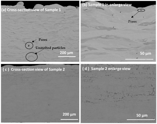
Figure 1.
(a–d) The cross-sectional image of plasma spray samples 1 and 2 with enlarged view.
The interface of the coating with the substrate shows a non-uniform heat-affected zone of around 10 microns. The presence of intermetallic compounds and an oxide layer confirmed from the EDX analysis of the back surface of the sample. The results of elemental composition are available in the supplementary file Figures S1–S4. This result has similar findings with other researchers [28,29,30]. The plasma spray parameters affect certain factors of the coating, such as the size and distribution of porosity, oxide content, residual stresses and macro and microcracks, factors which have an important influence on the performance of the coating as samples [31,32].
The elemental mapping for the above Figure 1 is displayed in the supplementary file (Figure S5) with Ti and Ni elements by electron distribution spectra (EDS) analysis.
The chemical composition along with the corresponding phases of plasma sprayed samples and its corresponding experimental parameters is presented in Table 1. The samples are prepared on the substrate stainless substrate and the thickness of the sample depends on the multiple times of spraying of powder.
XRD data for the samples are available as supplementary files (Figure S6) that confirmed the presence of martensite, austenite and intermetallic phases. Figure 2 displays the DSC curves for samples 1 and 2 with corresponding peaks during the cooling and heating cycle. The transformation temperature for both austenite, R-phase and martensite phases is presented in Table 2. The transformation temperatures for austenite and martensite phases for the powder plasma sprayed sample represents the start and finish temperatures. Table 2 shows the transformation temperatures of the plasma spraying powder used and samples.
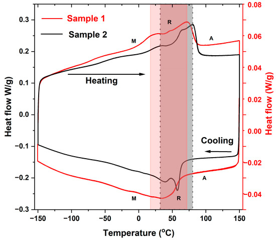
Figure 2.
Heat flow on the temperature used to determine the transition temperatures for various phases during heating and cooling in samples 1 and 2.
3.1. Thermo-Mechanical Response of the Sample
Figure 3a,b represents the static thermo-mechanical behaviour of the samples at a 500 mN load for multiple cycles. The shape memory behaviour was explored via static load bending under thermal cycles (cooling and heating). Figure 3a displays the multiple cycles of bending displacement under a static load. It has been observed that both samples do not return to same position with multiple cycles. There is accumulation of plastic strain that induces a decrease in recovery from the original displacement. The change in displacement from original position to the final position varies by −1 to −2 µm for samples 1 to 2.
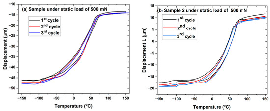
Figure 3.
(a,b) Samples 1 and 2 under a static load of 500 mN as displacement with temperature. (Due to the limitation of the cooling Dewar, three consecutive experiments could run simultaneously).
Figure 4a–d represents the shape memory effect of NiTi samples 1 and 2 at several testing temperatures and at various loads. The hysteresis character remains preserved for bending tests performed from bending load 500 to 300 MPa, exhibited in Figure 4a,b. The samples were loaded up to 1000 MPa with a follow up unloading at testing temperature. Figure 4c shows the sample response at a testing temperature of −25 °C, with an unrecovered strain of >1%. The unrecovered strain can be recovered by heating the sample above the austenite finish temperature. The sample shows a typical response for shape memory behaviour featuring a hysteresis character. The response of the samples 1 and 2 spans the behaviour from elastic to non-elastic (Figure 4c,d).
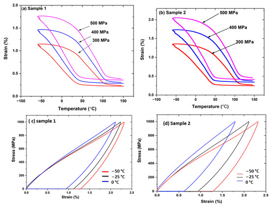
Figure 4.
(a–d). Bending test records for plasma sprayed samples 1 and 2. (a,b) Strain versus temperature at various loads. (a,b) strain-temperature hysteresis curves at various loads shows hysteresis effect (c,d) Stress-strain behaviour at various temperatures shows non-elastic (hysteresis) behaviour at low temperature. (Part of the figure belongs to reference [33]).
3.2. Indentation and Scratch Testing
Deformation behaviour and character of the material response were also explored via a set of localized tribo-mechanical experiments performed over the surface of the samples. Indentation tests and scratch and wear tests at various loads were all performed using spherical indenters with nominal radii of 5 and 10 um. During the indentation test, the indenter is loaded with gradually increasing force, resulting in the formation of a residual impression after reaching the macroscopic yield stress. At the maximum load, the deformed material below the indenter can be divided into three characteristic parts, i.e., the elastic region, the transformed region related to the shape memory behaviour that is temporarily contributing to the plasticity region surrounding the spherical indenter. The mechanism of distribution in various responses to stress is represented in Figure 5a–c. Figure 5a shows the response of the material during loading upon initiation of plastic deformation. On unloading, the recovery of the elastic region results in maintaining shape memory and a plasticity region (Figure 5b). On heating, the recovery of the shape memory region occurs leaving behind the plasticity region on the sample (Figure 5c).
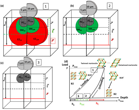
Figure 5.
(a–c) Schematic diagram of indentation load and depth as the function of elastic, shape memory and plastic effect from shape memory alloy. (1–3) Different deformation zones plastic zone (PZ), shape memory (SM) zone and elastic zone (EZ) regions on maximum load, unload position and after shape recovery. Two different radii of an indenter with radii of 5 and 10 µm. (d) Depth of maximum depth from hmax divided into height of elastic (hE), SM (hSM) and plastic (hp) zones for B2 (austenite) and B19’ martensite phases.
3.3. Indentation Behaviour of the Sample with Mechanical Elastic Recovery
Hardness and reduced elastic modulus values calculated for the normal load of 50, 100, 250 and 500 mN are shown in Figure 6a,b. The higher hardness and reduced modulus are observed at the lower indent radius of 5 µm for both samples. Hardness and the reduced modulus of samples are directly proportional to applied load [34].
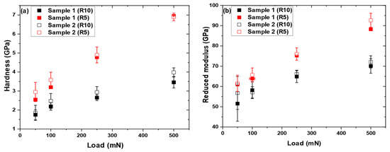
Figure 6.
(a) Hardness and (b) reduced modulus of samples 1 and 2 at various loads with indenter radii of 5 and 10 μm.
The deformation in plasma sprayed NiTi that happens due to the phase transition in the depth dependent on spherical hardness is illustrated in Figure 6a. Both purely elastic material and NiTi SMA show a similar trend in hardness–depth behaviour. Under the applied load the phase transition phenomenon makes the material soft and increases the depth by stress relaxation underneath the tip. The resultant contact area becomes larger and, therefore, the depth dependence of the hardness becomes less significant compared with purely elastic material. This fact is confirmed by the larger phase transition strains that lead to a lower spherical hardness under the same indentation depth (Figure 6). It is also observed that the more the phase transition strain (pseudoelasticity) is, the more the linear trend of the hardness and reduced modulus-load is achieved. In summary, spherical indentation tests on NiTi SMAs show a significant increase in the hardness and reduced modulus with indentation loads.
Figure 7a–d shows indentation depth-load curves for samples 1 and 2 for both indenter radii of 5 and 10 µm. The indent depth increases with increasing load. The residual depth represents the elastic recovery after unloading [35]. The applied load varies and is 50 mN, 100 mN, 250 or 500 mN on the sample that shows both the loading and unloading part of the curve. The unloading curve determines the elastic recovery in the sample after the applied force release. The elastic recovery from this set of the curve is determined from 10 points. The results of elastic recovery from mechanical loading are determined and calculated.
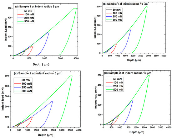
Figure 7.
(a–d) Load-depth curves of selected indentations using various loads and different radii of 5 and 10 µm.
Figure 8a,b illustrates the elastic recovery of both samples 1 and 2 after unloading at two indent radii of 5 and 10 µm. It has been observed that sample 2 shows better elastic recovery except at a higher load of 500 mN for an indent radius of 5 µm and at a lower load of 50 mN with a higher indent radius of 10 µm. This result may arise from the mixture rule of austenite and martensite phases. Sample 2 contains more martensite phases than sample 1. Elastic recovery arises from the resultant region of elastic half space. The half space consists of the phase transformation region from austenite to martensite, an inherent martensite phase that contributes towards elastic, SME and plastic regions.
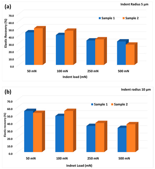
Figure 8.
(a,b) Elastic recovery for samples 1 and 2 at indent radii of 5 and 10 µm.
3.4. Thermal Recovery of Residual Indent Depth
The samples were subsequently annealed above austenite transformation temperature to observe the depth recovery of indents. The recovery ratio in the sample is calculated based on the equation 1, which could be able to quantify the indent recovery.
(dba − daa) can be considered as a measure of the amount of shape memory recovery and daa as the amount of plastic deformation. R is therefore the fraction of total deformation due to the shape memory effect. In this case, dba is the maximum indentation depth after unloading and daa is the depth of the residual indent after annealing. The value of (dba − daa) quantifies the combined effect of elastic and shape memory recovery, and daa is still a measure of plastic deformation.
Figure 5a–d represents the indent depths for samples 1 and 2 at various loads with indenter tip radii of 5 and 10 μm before and after annealing and their respective recoveries. The respective recoveries of the samples at 5 and 10 µm indent radii is estimated and plotted in Figure 5b,c. The error bars are estimated from the average 10 indent points. Indent depth at a lower load of 50 mN is not included in the plot due to the higher roughness of the sample surface evolving after annealing that precluded identification of residual indents made with the 10 µm spherical tip. Indents obtained with a 5 µm tip at 50 mN showed recoveries of 50–60 percent with high standard deviation and indents made with a 10 µm tip could no longer be measured. It can be said that at even lower loads the surface would be fully recovered. Considering the higher loads, sample 1 shows a maximum recovery of 60% at the 100 mN load and 40% recovery at the higher load of 500 mN. However, a reverse trend is observed for sample 2 at an indent radius of 5 µm. Both austenite and martensite phases are present in samples 1 and 2; however, martensite has more dominant phases compared with austenite in sample 2. Therefore, it has been estimated that recovery is more prominent in sample 2, which may arise from the shape memory behaviour of the sample from martensite phases that recovered during annealing, which contributes towards recovery. Figure 9a–d shows the microscopic image of the indent surface with 10 residual indent points at various loads for samples 1 and 2 at an indent radius of 5 µm before and after annealing. Residual indents are generally less marked in the annealing samples. It illustrates recoveries of indent depth after annealing. Figure 10a–d displays the image of the indent points at various loads for both samples at an indent radius of 10 µm. The increased surface roughness limits the measurement of remnant depth at lower loads after annealing on both samples.
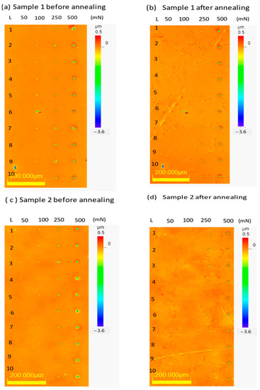
Figure 9.
(a–d) Microscopic images of samples 1 and 2 before and after annealing in height mode (10 indent points for each load of 50, 100, 250 and 500 mN) with a spherical indenter of radius 5 µm.
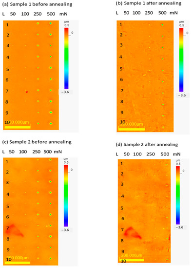
Figure 10.
(a–d) Microscopic images of samples 1 and 2 before and after annealing in height mode (10 indent points for each load of 50, 100, 250 and 500 mN) with a spherical indenter of radius 10 µm.
3.5. Surface Recovery of Scratch Lines
The sliding contact loading via a scratch test was performed to explore the possible differences in comparison with quasi-static indentation conditions. The scratch tests were used to induce different types of abrasive/scratching damage and to study subsequent volume recovery. Figure 8a,b shows the depth records of scratch tracks performed using 5 and 10 μm tips at 100 and 250 mN loads for sample 1. Three scratches were made in each test setup and depth changes were compared between initial topography, loaded scratch and final topography. The good overlap of three repetitions confirms good repeatability of the test and, in turn, surface homogeneity.
Table 3 shows the worn volumes (μm3) measured using the 3D imaging mode of a laser scanning confocal microscope before and after annealing. Sample 2 shows a higher worn volume recovery compared with sample 1 after annealing. The worn volume recovery, 32.5% for the higher load of 250 mN, is smaller than 39.7% recovery for the 100 mN load. Generally, the depth recovery of sample 2 is always comparably larger than for sample 1. The sample 2 worn volume recovery peaked at 46.9% and 48.7% for the 250 mN and 100 mN tests, respectively, both using the 10 μm tip. It is worth noting that the worn volume measurement was complicated by the irregular and warped surface of the samples after annealing. This was solved by flattening the sample on the sample holder and using software correction for the surface waviness (by subtraction of the third order polynomial).
Table 3.
Worn volume of scratches on samples 1 and 2 before and after annealing.
It should be noted that the thermally induced recovery (“heal”) is always higher for the single scratch pass in comparison to the multi-pass experiment composed of 10 scratches (compare Table 3 and Table 4). Although the scratch depth is comparable for the wear test performed at 100 mN (10 scratch passes) and the single scratch test at 250 mN, the recovery is always lower for the single scratch pass. Both facts reflect the more severe extent of plastic deformation that takes place at the expense of the pseudoplasticity related to the shape memory behaviour.
Table 4.
Line roughness of samples 1 and 2 before and after annealing.
3.6. Wear Test on the Sample with Recovery in Volume
The wear behaviour of NiTi SMA samples with the effects of wear mode, applied load and counter-wear materials have been reported [36]. In conventional wear-resistant materials, hardness is the predominant factor that determines their wear resistance. However, for NiTi SMA the temperature-related phase change has been suggested as the predominant factor that determines the wear resistance. It is known that the microstructure of NiTi SMA is temperature-dependent, which further leads to the temperature-dependence of the deformation mechanisms involved in the wear process. The wear behaviour of NiTi SMA is dependent on the deformation mechanisms involved in the wear test, whereas the deformation mechanism depends on the interplay between the contact stress/applied load and the test temperature.
Figure 11 displays the wear test for samples 1 and 2 with a 10 μm radius tip and a 250 mN load. The curves describe the evolution of each of the 16 scratch passes, with 10 performed under a constant load and 6 more in between them with only a small topographic load. The evolution of the on-load scratches shows an increase in the elasto-plastic deformation, whereas the topographic passes show the evolution of the residual scratch depth and, therefore, an increase in plastic deformation only. The wear test was performed on samples 1 and 2 at a 250 mN load with an indenter tip radius of 10 μm. The worn volume of the wear depth of samples 1 and 2 was measured before and after annealing at the 250 mN load and is represented in Table 3. It has been observed that sample 2 shows 40% recovery compared with sample 1 at the 250 mN load.
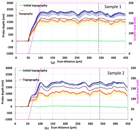
Figure 11.
(a,b) Wear response of samples 1 and 2 at a 250 mN load with an indent radius of 10 μm; shows probe depth and on-load depth.
The samples undergo indents with subsequent annealing and show significant recovery of residual indent points at a lower load of 50 mN. The residual indents are hardly visible on the annealed surface and show complete recovery, or it may be a due to complication in surface roughness in the measurement of the depth of the indent points (Figure 6 and Figure 7). The average recovery of 60% for the indent points after annealing is achieved for both samples. The surface recovery of the indent sample is achieved after annealing with more martensite phases that contribute towards the shape memory effect. The recovery is higher at an indent radius of 10 µm for both of the samples (Figure 12). This may be due to the depth of the indent at 10 μm being larger than the one at 5 μm.
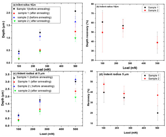
Figure 12.
(a–d) Indentation residual depths and subsequent recoveries after annealing of samples 1 and 2.
3.7. Elastic Recovery—Mechanical vs. Thermal
In general, two types of the elastic recovery can be considered for materials showing a shape memory effect in the case of the combined thermo-mechanical treatment/exposure.
The half space of the indent points is generally divided into three regions (Figure 2). Based on the indent depth from the various regions the recovery is achieved on two subsequent cycles. Elastic recovery allows the primary recovery of the sample after unloading the indent load. The elastic recovery arises from the mechanical recovery of the sample. The second part of the recovery derives from the annealing treatment of the sample that contributes to the shape memory part. The region that deforms through the martensite twin is labelled as the shape memory region.
If the sample is annealed past the austenite finish temperature Af, the transformation to the austenite phase will allow the sample to revert to its original form, which is retained by self-accommodating twins upon cooling to room temperature. Based on the sample behaviour towards shape memory effect, this determines the percentage of recovery of sample after annealing. The annealing induces a phase change from the martensite to the austenite phase above the transformation temperature (annealed temperature) that contributes towards the depth recovery in the samples. The residual indent depth remains in the sample, which may be attributed to the plasticity region. The region in which plastic deformation occurs, however, remains deformed. At lower loads, recovery is very significant and may arise from the combined effect of mechanical unloading and the thermal effect. The thermal recovery of samples is higher than the elastic recovery. Sample 2 shows better recovery in compared with sample 1, which may arise from the higher content of martensite phase with respect to the austenite phase. The maximum stress under the spherical indenter remains finite. The strain caused by the stress distribution under the spherical indenter was largely accommodated by winning mechanisms in the martensite, leading to shape recovery upon heating [30]. In the case of sample 1, the contribution of martensite is larger than sample 1, which leads to more recovery from deformation.
3.8. Roughness
Surface roughness evaluation is very crucial for analysis of friction, contact deformation and wear properties of materials [37]. Annealing of both NiTi samples also resulted in an increase in the roughness. This was one of the reasons why it was practically impossible to find residual indents at the lowest indentation of 50 mN, whose depths were comparable with the roughness. For higher load indentations (leading to higher depths) and the scratch test, the effect of increased roughness on the results was already negligible. In engineering practice, several types of roughness are considered: Ra is the arithmetic average height deviation from mean line; Rq (or Rms) is the root mean square average height deviations from mean line; Rz is the maximum peak to valley height averaged over the sampling length; and Rt (or Rmax) is the maximum height of the profile peak and profile valley over the evaluation length. The roughness parameters in our article were measured using a non-contact laser confocal microscope (LEXT). Identical areas on samples before and after annealing were always compared. A cutoff of λc = 100 um was always applied during the evaluation to reduce the influence of the sample waviness on the roughness values [32]. The results in Table 3 show an increase in all roughness parameters, with sample 2 having slightly higher values after annealing compared with sample 1.
4. Conclusions
In this work the shape recovery of two shape memory NiTi alloys prepared by plasma spraying has been investigated using the indentation technique and laser confocal microscopy. Indentation depths and worn volumes of two variants of the scratch test were analysed before and after annealing. The findings show that the indentation depth, scratch depth and wear depth recovery ability of the NiTi depends on the phase composition of samples. The selection of the annealing temperature corresponds to the temperature of the austenite finish temperature that induces a phase change during annealing that could participate towards shape recovery in the material. Sample 2 shows a maximum 60% indent recovery of, 48.7% scratch recovery and 40.7% wear depth recovery for the load of 100 mN at a tip radius of 10 μm. We have also observed that the annealing temperature has significant effect on the surface deformation recovery of the samples. The elastic surface recovery reduced with multiple scratch lines, which confirmed the induction of plasticity from the thermo-mechanical behaviour of the sample. Sample 2 shows a better result in thermal recovery that may arise from the volume fraction of the martensite region towards the shape memory region. There will be a significant application for the plasma sprayed NiTi samples on the surface recovery in the wear application.
Supplementary Materials
The following supporting information can be downloaded at: https://www.mdpi.com/article/10.3390/coatings13020433/s1, Figure S1: (a,b) Cross-section surface of sample 1 in BSE and SE mode (c,d) Back surface of sample 1; Figure S2: EDX analysis of back surface of sample 1 (two different location).; Figure S3: (a,b) Cross-section surface of sample 2 in BSE and SE mode (c,d) Back surface of sample 2 at different location; Figure S4: EDX analysis of the back surface; Figure S5: Elemental mapping for Ni and Ti in sample 1 and 2, that corresponds to Figure S1 (a and c); Figure S6: XRD spectrum for sample 1 and 2 with martensite, austenite and intermetallic peaks.
Author Contributions
During the process of completing this paper, S.S. and P.Š. conceived and designed the study and wrote the manuscript. O.M. has performed image analysis by using SEM for the samples. R.Č., L.V. and J.T. performed and evaluated indentation, scratch and wear tests on the samples and performed tribological analysis of the samples. All authors have read and agreed to the published version of the manuscript.
Funding
This research was funded by project 22-20181S and SOLID 21 (CZ.02.1.01/0.0/0.0/16_019/0000760). Authors also gratefully acknowledge the support by the Operational Program Research, Development and Education, Projects No. CZ.02.1.01/0.0/0.0/17_049/0008422 of the Ministry of Education, Youth and Sports of the Czech Republic and internal students grant of Palacky University in Olomouc IGA_PrF_2023_005.
Institutional Review Board Statement
Not applicable.
Informed Consent Statement
Not applicable.
Data Availability Statement
The data will be available on request from the corresponding author.
Acknowledgments
First author would like to acknowledge Institute of Plasma Physics for the contribution of preparation of samples for this study.
Conflicts of Interest
The authors declare no conflict of interest.
References
- Otsuka, K.; Ren, X. Physical metallurgy of Ti-Ni-based shape memory alloys. Prog. Mater. Sci. 2005, 50, 511–678. [Google Scholar] [CrossRef]
- Lai, A.; Du, Z.; Gan, L.C. Shape memory and superelastic ceramics at small scales. Science 2013, 341, 1505–1508. [Google Scholar] [CrossRef] [PubMed]
- Wang, J.; Moumni, Z.; Zhang, W.; Zaki, W. A thermomechanically coupled finite deformation constitutive model for shape memory alloys based on Hencky strain. Int. J. Eng. Sci. 2017, 117, 51–77. [Google Scholar] [CrossRef]
- Samal, S.; Molnárová, O.; Průša, F.; Kopeček, J.; Heller, L.; Šittner, P.; Škodová, M.; Abate, L.; Blanco, I. Net-Shape NiTi Shape Memory Alloy by Spark Plasma Sintering Method. Appl. Sci. 2021, 11, 1802. [Google Scholar] [CrossRef]
- Samal, S.; Cibulková, J.; Čtvrtlík, R.; Tomáštík, J.; Václavek, L.; Kopeček, J.; Šittner, P. Tribological Behavior of NiTi Alloy Produced by Spark Plasma Sintering met hod. Coatings 2021, 11, 1246. [Google Scholar] [CrossRef]
- Tanaka, Y.; Himuro, Y.; Kainuma, R.; Sutou, Y.; Omori, T.; Ishida, K. Ferrous polycrystalline shape-memory alloy showing huge superelasticity. Science 2010, 327, 1488–1490. [Google Scholar] [CrossRef] [PubMed]
- Abedini, M.; Ghasemi, H.; Ahmadabadi, M.N. Tribological behavior of NiTi alloy against 52100 steel and WC at elevated temperatures. Mater. Charact. 2010, 61, 689–695. [Google Scholar] [CrossRef]
- Abedini, M.; Ghasemi, H.M.; Nili Ahmadabadi, M. Tribological behavior of NiTi alloy in martensitic and austenitic states. Mater. Des. 2009, 30, 4493–4497. [Google Scholar] [CrossRef]
- Clayton, P. Tribological behavior of a titanium-nickel alloy. Wear 1993, 162–164, 202–210. [Google Scholar] [CrossRef]
- Kwok, C.T.; Wong, P.K.; Man, H.C. Enhancement in corrosion and electrical wear resistance of copper via laser surface alloying with NiTi. Surf. Coat. Technol. 2021, 408, 126804. [Google Scholar] [CrossRef]
- Gialanella, S.; Ischia, G.; Straffelini, G. Phase composition and wear behavior of NiTi alloys. J. Mater. Sci. 2008, 43, 1701–1710. [Google Scholar] [CrossRef]
- Bitzer, M.; Rauhut, N.; Mauer, G.; Bram, M.; Vaßen, R.; Buchkremer, H.-P.; Stöver, D.; Pohl, M. Cavitation-resistant NiTi coatings produced by low-pressure plasma spraying (LPPS). Wear 2015, 328–329, 369–377. [Google Scholar] [CrossRef]
- Espitia, L.; Dong, H.; Li, X.-Y.; Pinedo, C.; Tschiptschin, A. Cavitation erosion resistance and wear mechanisms of active screen low temperature plasma nitrided AISI 410 martensitic stainless steel. Wear 2015, 332–333, 1070–1079. [Google Scholar] [CrossRef]
- Imbeni, V.; Martini, C.; Prandstraller, D.; Poli, G.; Trepanier, C.; Duerig, T. Preliminary study of micro-scale abrasive wear of a NiTi shape memory alloy. Wear 2003, 254, 1299–1306. [Google Scholar] [CrossRef]
- Farvizi, M.; Ebadzadeh, T.; Vaezi, M.; Yoon, E.; Kim, Y.-J.; Kang, J.; Kim, H.; Simchi, A. Effect of starting materials on the wear performance of NiTi-based composites. Wear 2015, 334-335, 35–43. [Google Scholar] [CrossRef]
- Momeni, S.; Tillmann, W. Investigation of the self-healing sliding wear characteristics of NiTi-based PVD coatings on tool steel. Wear 2016, 368–369, 53–59. [Google Scholar] [CrossRef]
- Feng, X.-Q.; Qian, L.; Yan, W.; Sun, Q. Wearless scratch on NiTi shape memory alloy due to phase transformational shakedown. Appl. Phys. Lett. 2008, 92, 121909. [Google Scholar] [CrossRef]
- Tang, G.; Ho, J.K.; Dong, G.; Hua, M. Fabrication self-recovery bulge textures on TiNi shape memory alloy and its tribological properties in lubricated sliding. Tribol. Int. 2016, 96, 11–22. [Google Scholar] [CrossRef]
- Ni, W.; Cheng, Y.-T.; Grummon, D.S. Recovery of microindents in a nickel–titanium shape-memory alloy: A “self-healing” effect. Appl. Phys. Lett. 2002, 80, 3310–3312. [Google Scholar] [CrossRef]
- Richman, R.; Rao, A.; Hodgson, D. Cavitation erosion of two NiTi alloys. Wear 1992, 157, 401–407. [Google Scholar] [CrossRef]
- Stella, J.; Schüller, E.; Heßing, C.; Hamed, O.; Pohl, M.; Stöver, D. Cavitation erosion of plasma-sprayed NiTi coatings. Wear 2006, 260, 1020–1027. [Google Scholar] [CrossRef]
- Hutchings, I.M. Tribology, Friction and Wear of Engineering Materials; Edward Arnold: London, UK, 1992. [Google Scholar]
- Glaeser, W.A. Materials for Tribology; Elsevier Science: Amsterdam, The Netherlands, 1992. [Google Scholar]
- Levintant-Zayonts, N.; Starzynski, G.; Kopec, M.; Kucharski, S. Characterization of NiTi SMA in its unusual behaviour in wear tests. Tribol. Int. 2019, 137, 313–323. [Google Scholar] [CrossRef]
- Arciniegas, M.; Casals, J.; Manero, J.M.; Peña, J.; Gil, F.J. Study of hardness and wear behaviour of NiTi shape memory alloys. J. Alloy. Compd. 2008, 460, 213–219. [Google Scholar] [CrossRef]
- Wang, Y.; Xu, R.; Hu, S.; Tu, F.; Jin, W. Research combining experiment and FEM analysis on sliding wear behaviors and mechanisms of TiNi alloy. Wear 2017, 386-387, 218–222. [Google Scholar] [CrossRef]
- Samal, S.; Tyc, O.; Cizek, J.; Klecka, J.; Lukáč, F.; Molnárová, O.; de Prado, E.; Weiss, Z.; Kopeček, J.; Heller, L.; et al. Fabrication of Thermal Plasma Sprayed NiTi Coatings Possessing Functional Properties. Coatings 2021, 11, 610. [Google Scholar] [CrossRef]
- Ozel, S.; Kurt, B.; Somunkiran, I.; Orhan, N. Microstructural characteristic of NiTi coating on stainless steel by plasma transferred arc process. Surf. Coatings Technol. 2008, 202, 3633–3637. [Google Scholar] [CrossRef]
- Swain, B.; Mallick, P.; Mohapatra, S.S.; Behera, A.; Rajak, D.K.; Menezes, P.L. Atmospheric Plasma Spray Coating of NiTi on Mild Steel Substrate: An Microstructural Investigation. J. Bio-Tribo-Corrosion 2021, 7, 104. [Google Scholar] [CrossRef]
- Samal, S.; Kopeček, J.; Šittner, P. Interfacial Adhesion of Thick NiTi Coating on Substrate Stainless Steel. Materials 2022, 15, 8598. [Google Scholar] [CrossRef] [PubMed]
- Fauchais, P.; Vardelle, M.; Vardelle, A.; Bianchi, L. Plasma spray: Study of the coating generation. Ceram. Int. 1996, 22, 295–303. [Google Scholar] [CrossRef]
- Swain, B.; Mallick, P.; Bhuyan, S.K.; Mohapatra, S.S.; Mishra, S.C.; Behera, A. Mechanical Properties of NiTi Plasma Spray Coating. J. Therm. Spray Technol. 2020, 29, 741–755. [Google Scholar] [CrossRef]
- Yan, L.; Liu, Y. Effect of temperature on the wear behavior of NiTi shape memory alloy. J. Mater. Res. 2014, 30, 186–196. [Google Scholar] [CrossRef]
- Amini, A.; Cheng, C. Nature of hardness evolution in nanocrystalline NiTi shape memory alloys during solid-state phase transition. Sci. Rep. 2013, 3, srep02476. [Google Scholar] [CrossRef]
- Tang, G.; Zhang, D.; Zhang, J.; Lin, P.; Dong, G. Self-recovery of worn surface of TiNi shape memory alloy. Appl. Surf. Sci. 2014, 321, 371–377. [Google Scholar] [CrossRef]
- Gadelmawla, E.S.; Koura, M.M.; Maksoud, T.M.A.; Elewa, I.M.; Soliman, H.H. Roughness parameters. J. Mater. Process. Technol. 2002, 123, 133–145. [Google Scholar] [CrossRef]
- Available online: https://www.spectrum-metrology.co.uk/surface-roughness/theory.php (accessed on 1 July 2017).


Disclaimer/Publisher’s Note: The statements, opinions and data contained in all publications are solely those of the individual author(s) and contributor(s) and not of MDPI and/or the editor(s). MDPI and/or the editor(s) disclaim responsibility for any injury to people or property resulting from any ideas, methods, instructions or products referred to in the content. |
© 2023 by the authors. Licensee MDPI, Basel, Switzerland. This article is an open access article distributed under the terms and conditions of the Creative Commons Attribution (CC BY) license (https://creativecommons.org/licenses/by/4.0/).