Review

Multi-Scale Structural Design and Advanced Materials for Thermal Barrier Coatings with High Thermal Insulation: A Review

School of Materials Science and Engineering, Xi’an Shiyou University, Xi’an 710065, China
*
Author to whom correspondence should be addressed.
Coatings 2023, 13(2), 343; https://doi.org/10.3390/coatings13020343
Submission received: 9 December 2022 / Revised: 15 January 2023 / Accepted: 18 January 2023 / Published: 2 February 2023

Abstract

:
Thermal barrier coatings (TBCs) are a fundamental technology used in high-temperature applications to protect superalloy substrate components. However, extreme high-temperature environments present many challenges for TBCs, such as the degradation of their thermal and mechanical properties. Hence, highly insulating, long-life TBCs must be developed to meet higher industrial efficiency. This paper reviews the main factors influencing the thermal insulation performance of TBCs, such as material, coating thickness, and structure. The heat transfer mechanism of the coating is summarized, and the degradation mechanism of the thermal insulation is analyzed from the perspective of the coating structure. Finally, the recent advances in improving the thermal insulation and lifetime of coatings are reviewed in terms of advanced materials and structural design, which will benefit advanced TBCs in future engineering applications and provide guidance for the next generation of high thermal insulating TBCs.

1. Introduction

Thermal barrier coatings (TBCs) are a multilayer coating of a combination of low thermal conductivity, high melting-point ceramics and alloy materials deposited on a nickel-based, high-temperature alloy to reduce the surface temperature [1,2,3]. TBCs are used widely to provide thermal protection on the high-temperature components of aero engines and land-based gas turbines and in the high-temperature manufacturing industry (Figure 1) [4,5]. Increasing the turbine inlet temperature can effectively improve the efficiency of gas turbines and the thrust-to-weight ratio of aero engines. As the demand for electric power and supersonic flights increases, the operating temperature of next-generation engines will exceed 1500 °C [6], which is higher than the operating temperature of nickel-based alloys. Therefore, the thermal insulation and durability of TBCs need to be improved significantly.
Typical TBCs consists of a topcoat (TC), a bond coat (BC), a thermally grown oxide (TGO), and a substrate (SUB). The functions of the TC are thermal insulation and resistance to calcium–magnesium–alumina–silicate (CMAS) corrosion. The functions of the BC are bond strengthening, oxidation resistance, and mechanical property transition [7,8,9,10,11,12,13]. The BC is typically a metal layer of MCrAlY (M = Fe, Ni, Co, or Ni–Co) [14,15,16]. The TC material selected must meet strict performance limits to resist thermal and mechanical attacks in extreme environments. These include high melting point, good strain tolerance, corrosion resistance, low sintering rate, no phase change during thermal cycling, and a coefficient of thermal expansion (CTE) that matches the metal matrix [17,18]. Y2O3-stabilized ZrO2 (YSZ) is used widely as a TC material owing to its good properties [19,20,21]. However, YSZ undergoes a phase transformation at operating temperatures above 1300 °C, leading to volume expansion. In addition, sintering occurs, damaging the strain tolerance and reducing the lifetime of TBCs [22,23]. Therefore, advanced TBC materials with better high-temperature stability and lower thermal conductivity are needed.
Conventional TBCs are mainly prepared by plasma spraying (PS) and electron beam physical vapor deposition (EB-PVD) [4]. A previous study reported that the PS-TBC coating exhibited approximately 60% lower thermal conductivity than the bulk due to the lamella structure containing many inter-splat pores [24]. The TBC prepared by EB-PVD exhibited a columnar structure with multi-scale pores. Vertical global-scale channels separate the columnar grains, while nanoscale voids are produced inside the columnar grains. The thermal conductivity decreases by less than 40% compared to that of the bulk material because the intercolumnar pores are aligned in the direction of heat flux [25]. Currently, many methods have also been developed for the preparation of TBCs; the potential and representative techniques include suspension plasma spraying (SPS) and plasma spraying physical vapor deposition (PS-PVD) (Figure 2) [26,27,28]. The PS-PVD process is a conventional method based on the low-pressure plasma spraying of TBCs. The increased efficiency of vacuum pumps in PS-PVD installations resulted in pressures in the working chamber between 50 and 200 Pa. Owing to the low pressure in the process, the plasma plume can reach lengths of more than 2 m and diameters of 200–400 mm [29,30]. SPS is an emerging technology that can replace atmospheric PS (APS) to manufacture thinner layers. A suspension of submicron particles can be introduced into a plasma stream via an axial or radial injection. A continuous stream of suspension flows from an injector of tens of microns and is injected into the plasma stream. The first fragmentation occurs in the plasma stream, and solvent evaporation occurs before the particles are simultaneously accelerated and melted until the particles hit the surface [31]. TBCs prepared using these two techniques have a columnar structure similar to that prepared by EB-PVD, which can improve the strain tolerance of the coatings. In addition, they have higher intracolumnar porosity, which can reduce the thermal conductivity of the coating [32], so they have been studied widely for the preparation of next-generation advanced TBCs.
This paper reviews the thermal properties and influencing factors of TBCs and recent research strategies to improve their thermal insulation and durability. First, the factors affecting the thermal insulation of coatings are discussed from the aspects of material properties, coating thickness, and internal microstructure. The leading causes of thermal insulation degradation due to thermal exposure are analyzed. Finally, the related designs for high thermal insulation and long-lifespan coatings are discussed (Figure 3).

2. Influencing Factors in Thermal Insulation

The heat absorption and release of the TBC is a balanced process, and this thermal equilibrium process can be considered a steady-state heat transfer. The TBC is generally thin in the range of 200–3000 μm, and the dimensions parallel to the substrate direction can be approximated to infinity compared to the thickness direction. Therefore, the heat transfer process of a TBC can be regarded as a one-dimensional, steady-state heat transfer perpendicular to the coating surface. According to Fourier’s law, the longitudinal unit thermal resistance of the coating can be expressed as follows [41]:
R = H λ A ,
where H is the thickness of the coating, λ is the thermal conductivity, and A is the area normal to the heat flow. Under one-dimensional, steady-state heat transfer, the thermal conductivity of the TBC depends on both the coating material and the structure. A comprehensive understanding of the heat transfer and thermal insulation degradation mechanisms of coatings is essential for the development of high thermal insulation TBCs.

2.1. Thickness of the Top Coat

The service environment of aviation and industrial gas turbines is different, so the requirements for TBCs on turbine blades are also different. The service time of aero-engine TBCs is thousands of hours, and it is started and stopped continuously [1], which requires a high strain tolerance TBC prepared by EB-PVD (Figure 4). Heavy-duty gas turbines need to maintain high temperatures and high efficiency for a long time, and require high thermal insulation TBCs prepared with APS [42,43]. The thickness of TBCs is often larger than that needed for aviation (Figure 5).
Increasing the thickness of the topcoat is a promising technique for improving the thermal insulation potential by preserving its mechanical properties [46,47]. However, this causes a larger thermal gradient across the coating and higher stress within the topcoat. In addition to the thermal gradient stress, a higher thickness causes the higher elastic stress energy stored within the coating, which may lead to the initiation and propagation of cracks [48,49,50]. For the cooling phase with a transient thermal gradient, Sundaram et al. [51] numerically determined the transient energy release rate and mode fixity for coating delamination to be dependent on the initial thermal gradient, the rate of cool down, the substrate thickness, and the substrate constraint against bending. When the substrate thickness was fixed to 3.5 mm, the energy release rate increased monotonically with the coating thicknesses of 0.15, 0.45, and 0.75 mm. Li et al. [48] investigated the effects of the thickness and mechanical load on the energy release rate of the dwelling phase. The results show that when the substrate thickness is fixed, the topcoat thickness increases, and the energy release rate increases. Mohammadzaki Goudarzi et al. [52] prepared a TBC (TC 280 μm +BC 100 μm) and a thick TBC (TTBC TC 1000 μm +BC 100 μm) using a plasma spray process and investigated their thermal insulation and durability. The scanning electron microscopy image of the polished cross-section of as-sprayed TBC and TTBC showed distributed 2D pores and globular voids (Figure 6). As shown in Figure 7, a continuous oxide scale formed at the interface of NiCrAlY/YSZ. There is no sign of horizontal cracking or debonding in the conventional TBC. On the other hand, complete delamination occurred within the TTBC, with the delamination located within the top layer near the interface. The TGO of TTBC grew at a lower rate and failed mainly due to the higher temperature drop of the thicker coating, hence the higher internal stresses at the interface between the BC and the topcoat [53]. In addition, the delamination was driven by the high elastic strain within the topcoat caused by the higher thickness [46]. The thermal insulation of TTBC was two times that of a TBC. However, the life and bond strength of the TTBC were only approximately 43% of a TBC (Figure 8). Liang et al. [54] examined the effects of the coating thickness on fracture under thermal shock cycling by combining their thermal shock experiments with the corresponding finite element analysis. The results suggested that coatings with thicknesses greater than 300 μm were prone to failure after fewer cycles, and the coating interface cracking was more significant. The 500 μm coatings failed at only 16.6% of the number of cycles for the 100 μm coatings; the potential failure mechanism is the higher compressive stress of thicker coatings. Vo et al. [55] investigated the effect of the TBC thickness on realistic high-pressure turbine cooling-blade heat transfer using high-quality meshes based on the Mosaic meshing technique. The results showed that the blade surface temperature decreases with increasing TBC thickness (Figure 9). The blade coated with a 0.2 mm thick TBC reduced the blade surface temperature by 230 K (from 1150 to 920 K) compared to the blade without the TBC coating. The TBC thickness increased by 0.2 mm, resulting in an approximately 40 K decrease in the maximum blade temperature. Under the existing conditions, 250 μm thick TBCs can reduce the surface temperature of the blade substrate by 384–440 K [56]. The TBC thickness is significant for preventing heat transfer to the blade surface. However, spallation of TTBCs during gas turbine engine operating conditions is one of the major problems in the development and application of these coatings.

2.2. Materials and Structure of Top Coats

The heat transfer mechanism in conventional TBCs consists mainly of phonon heat conduction (crystal lattice vibration) within the YSZ material, photon heat transfer (thermal radiation), and gas-phase heat conduction and Knudsen heat transfer within the gas pores [57]. For electrically insulating ceramic materials, electrons do not contribute to the heat transfer process. For TBCs in the medium- to high-temperature range, the heat transfer process of the material is mainly phonon transport [58,59]. Based on the Debye theory, the contribution of lattice vibrations to heat conduction according to phonon dynamics theory is:
K p = 1 3 C v ρ v l p ,
where Cv is the specific heat capacity per unit volume of the material, ρ is the density, v is the phonon velocity, and lp is the phonon mean-free range. Cv, ρ, and v are influenced mainly by the type of material. The phonon mean-free range lp is the parameter with the greatest influence on the thermal conductivity of TBCs. The contribution of phonons to heat transfer is inversely proportional to the mean-free range of phonon scattering, which is closely related to the microstructure of the material. The scattering processes of phonons can be generally classified into three main categories: phonon-boundary scattering, phonon-defect scattering, and phonon–phonon scattering. According to the Matthiessen rule, the effects of the three scattering processes on the mean-free range of phonons can be quantified as follows:
1 l = 1 l defect + 1 l boundary + 1 l phonon ,
where ldefect, lboundary, and lphonon denote the effect of defects, boundary, and other phonons on the phonon mean-free range, respectively. A large number of defects and pore boundaries inside the TBC (Figure 10) affect the average free range of its internal molecules. The enhanced scattering of particles significantly affects the thermal conductivity of the coating [60]. After thermal exposure of TBC, the average free range of phonons increases. Hence, the proportion of photon heat transfer increases, and the contribution of photon heat transfer to thermal conductivity can be expressed as:
K r = 16 3 σ n 2 T 3 l r ,
where σ is the Stephen–Boltzmann constant, n is the refractive index, T is the absolute temperature, and lr is the photon scattering mean-free path. When the temperature is lower than 1200 °C, YSZ transfers heat mainly by phonons, but when the temperature increases, the proportion of photon heat transfer becomes larger (10% of the total heat transfer at 1250 °C). Therefore, for future high-performance engines, thermal radiation is an important factor affecting their performance and efficiency. The lamella structure of the PS-TBC can reduce the radiation heat transfer of TBCs.
The thermal conductivity of gas inside the pore in TBC can be calculated using the Kg model for the thermal conductivity of a gas inside a restricted air channel with a characteristic length dv, which can be calculated using the following equation [62]:
K g = K g 0 1 + B T / ( d v P ) ,
where P is the pressure, T is the absolute temperature, Kg0 is the unconstrained conductivity of a gas at the temperature concerned, and B is a constant that generally depends on the gas type and the solid surface material, surface roughness, and gas–solid interactions [63]. Indeed, the magnitude of the gas pressure P and the gas temperature T directly affect the molecular mean-free range λ of the gas inside the pore, significantly affecting the thermal conductivity of the gas phase inside the pore and its thermal conductivity. At atmospheric pressure, the molecular mean-free range λ is larger than the characteristic length dv of the pore, and Knudsen heat transfer occurs in the pore, which causes the thermal conductivity Kg of the gas inside the pore to be much lower than that of the free gas at the same temperature. Kg barely changes with temperature and does not increase with temperature similar to the free-space gas thermal conductivity Kg0, which is beneficial to the overall thermal insulation performance of the TBC. However, under the high-pressure conditions of a TBC, the average free range of molecules will be smaller than the characteristic length of the pore, and the thermal conductivity of the gas in the pore will be larger than that of the gas in the pore at atmospheric pressure. Moreover, the thermal conductivity of the gas in the pore will increase with increasing temperature. The value will be close to the thermal conductivity of the gas in the free space with increasing pressure, which will adversely affect the overall thermal insulation property of the TBC.
Many traditional empirical formulas have been proposed to calculate the effective thermal conductivity of coatings [64,65,66,67,68]. Neuer et al. [69] studied the effect of the porosity of YSZ coatings on the thermal insulation performance and reported that the relationship between the porosity and thermal conductivity of TBCs is:
λ p = λ 0 ( 1 β p ) ,
where λ0 is the thermal conductivity of the bulk material, β is a constant, and p is the porosity of TBCs. A simulation of the geometric arrangement and heat flows through it is required to incorporate the effects of heat transfer through the gas in the pores and within the zirconia itself and the pore architecture [70,71]. Golosnoy et al. [72] established analytical and numerical models for simulating heat flow through a two-component structure consisting of a solid layer separated by thin, periodically bridged, gas-filled voids, designed to represent plasma-sprayed ceramic coatings. It is based on dividing the modeling domain into two regions: (1) unidirectional conduction successively through the splits and the intervening air gaps and (2) channel conduction through bridges (bonding area). The results predict that the bridge area is the microstructural parameter with the greatest impact on the conductivity. Several factors play significant roles in determining the thermal conductivity, such as pore size, pore distribution, and crack orientation [73,74,75,76,77,78,79,80,81]. Wei et al. [82] developed an analytical model to discuss the effects of the microstructural parameters, including splat thickness, bonding ratio between splits, and unit size, on the total thermal resistance and to reveal the dominant effect of oriented 2D pores on heat flux (Figure 11) [72,82,83]. The thermal conductivity is strongly associated with the 2D composited stacking structure: bulk splits and air-trapped pores, and microstructural parameters, including splat thickness, splat/splat bonding ratio, and splat length contribute to total thermal resistance.
Higher porosity corresponds to lower thermal conductivity. However, at the service temperature, the radiation heat transfer caused by the pores cannot be ignored [84,85,86,87,88]. Numerous studies have shown that pores parallel to the direction of the substrate can drastically reduce the thermal conductivity [41,62,67,73,89,90,91]. Boissonnet et al. [92] prepared a series of TBCs with different thicknesses by PS and high-velocity oxygen-fuel spraying (Figure 12). They reported that the thermal diffusivity values decreased linearly with increasing lamellar porosity. The dependence of the thermal diffusivity on the porosity decreased at high temperatures (Figure 13). Sun et al. [73] investigated the thermal conductivity of various TBC pore morphologies by numerical methods. The thermal conductivity decreased as the total porosity increased, and the TBC with pores in the 0° direction (vertical to heat flow) had the lowest thermal conductivity. Furthermore, from 0° to 60° in the pore direction, the thermal conductivity decreased as the pore aspect ratio increased (Figure 14). In summary, the porosity level affects the thermal conductivity of the coating, while the pore morphology, aspect ratio, and temperature further influence the dependence of porosity and thermal insulation of the coating.
Therefore, the inherent thermal conductivity of the bulk material and the thickness and multi-scale pore structure of the coating are the key factors in improving the thermal insulation performance of TBCs [41,93,94,95].

2.3. Degradation Mechanism of Thermal Insulation

The thermal conductivity of TBCs increases significantly after thermal exposure, resulting in a decrease in the thermal insulation of the coating. Boissonnet et al. [92] suggested that the thermal diffusivity of self-standing TBCs and full TBCs increases by approximately 40% after thermal exposure (Figure 15), but the self-standing thermal diffusivity first increased, then decreased, and then stabilized because of the generation of many cracks during cooling. Cernuschi et al. [96] reported a similar increase in thermal diffusivity with heat treatment time. A higher temperature resulted in a more severe increase (Figure 16). The thermal conductivity of coatings becomes much more complicated in actual service. The main problem is that the evolution of the microstructure of TBCs by thermal service causes a change in the thermal conductivity of the coating [97,98,99].
Sintering leads to an approximate 80% increase in thermal conductivity [77,98,100,101]. Many studies attributed this to the significant healing of oriented 2D pores [85,101,102,103,104,105,106,107]. Li et al. [23] reported the comprehensive sintering mechanism for lamellar TBCs. An overall property evolution with two-stage kinetics was presented during thermal exposure. The first stage (0–10 h) resulted in faster sintering kinetics and increased mechanical properties due to the rapid healing caused by multipoint connection at the inter-splat pore tips, as well as a small quantity of narrow intra-splat cracks.
A previous study [61] reported the dynamic evolution of a coating sintered at high temperatures and the healing mechanism of 2D pores. Figure 17 shows the structural changes to the two types of pores with different widths during thermal exposure. The grains begin to grow within a relatively short time after thermal exposure, and the upper and lower surfaces of the pores become rough. Several diffusions short-circuit channels are formed in the pores, accelerating the high-temperature evolution typical of pore healing (Figure 17a). In addition, the wider 2D pores are not completely healed after the same thermal exposure (Figure 17b), and still maintain the narrow and long 2D features. However, the point of contact in the narrow area separates the 2D pores into several small pores, which resulted in a reduction in the aspect ratio of the 2D pores, thereby impairing the thermal insulation properties of the coating. Liu et al. [103] characterized the evolution of interlamellar 2D pores of the APS LZO coatings during exposure to high temperatures for different durations. The aspect ratio of the interlamellar 2D pores in the as-sprayed coating was more than 50. As the exposure duration increased, grain bridging segmented long gaps into several regions and reduced most pores to smaller ones with smaller aspect ratios. This led to a rapid decrease in the aspect ratio of the residual 2D pores at the early stage. The aspect ratio of most residual 2D pores after five hours of thermal exposure became less than 30. After thermal exposure, the aspect ratio was distributed mainly from 10 to 30. This sintering effect increases the stiffness and thermal conductivity of TBCs (Figure 18). Therefore, the healing of 2D pores and the increase in the aspect ratio at high temperatures are the main reasons for the increase in the thermal conductivity of TBCs [77,98,103,108].

3. Strategies to Enhance the Thermal Insulation of TBCs

The thermal insulation and lifetime of TBCs curb the efficiency and reliability of the gas turbine. According to the previous section, the improved thermal insulation of TBCs can be achieved by increasing the thickness of the ceramic layer, reducing the thermal conductivity of the ceramic material, and adjusting the multi-scale structure of the coating. However, ceramic layer thickness and low thermal conductivity of ceramic materials subjected to thermal stress and fracture toughness affect the lifetime of TBCs. Combining with a multi-scale structural design approach may be an effective way to solve this problem. Some potential ceramic materials and structural designs are summarized, which will guide the development of high thermal insulation and long life TBCs.

3.1. Enhanced Durability of TTBCs

TTBCs (>500 μm) are effective in thermal insulation [47,49,54,110,111]. Owing to the difference in thermal expansion coefficients between TCs and the substrate, a greater TC thickness indicates a greater thermal gradient within the coating and thermal mismatch stresses, elastically stored strain energy, and the energy release rate for crack formation, resulting in lower bonding strength and faster TTBC degradation [53,112,113,114,115,116,117]. Furthermore, the singularity of the stress at the coating-free edge also influences the failure of the coatings [118]. The broken regions usually occur at the horizontal and vertical cracks within the TC and TC/BC interfaces [17,119,120,121,122,123].
As the thermomechanical properties of TBCs are strongly dependent on the microstructure of the coating [61,75,93,124,125], the structure can be optimized in terms of the chemical composition, pore and crack distribution to achieve high thermal insulation and a long lifespan. Some methods to tailor the microstructure have been reported, including segmentation-cracked coatings, porous coatings, dense coatings, columnar coatings, gradient coatings, or multilayer coatings, by optimizing the spraying parameters or adopting various powders [50,126,127,128,129,130,131,132]. TTBCs exhibit a range of properties according to their structures.

3.1.1. Functionally Graded TTBCs

The tendency of the internal cracks of a TC to extend due to poor fracture toughness is a major problem [128]. Many researchers have fabricated gradient-structured YSZ-TBCs, which appeared to be a good option for improving the fracture toughness near the TC/BC interface of a TTBC [133,134,135]. Gradient coatings can reduce interfacial stress and increase fracture toughness [127,128]. The gradient structure has two forms: structural gradient and component gradient. The spraying power and gas flow rate altered the morphology of the splits, resulting in different coating structures obtained by subsequent deposition [136]. Functionally graded TBCs were sprayed by varying the feeding ratio of YSZ/NiCrAlY powders.
The porosity and pore shape are the key parameters controlling the mechanical properties and sintering behavior of TBCs [137,138]. Low porosity is beneficial to the fracture toughness of the coating, and high porosity is beneficial to maintaining strain tolerance. The functional structure classification can provide a coating with different microstructures on the longitudinal scale to give the coating strong integrated mechanical properties. The graded coating releases the driving force energy to fail while preventing the crack length [139]. To improve the fracture toughness of the TC layer near the BC, Li et al. [129] designed three layers of TBCs with different microstructures. The layer adjacent to the BC has continuous columnar grains to achieve crack extension resistance. The upper layer uses conventional and porous coatings to transition and improve the thermal insulation, respectively. This can increase the thermal cycle life of the coating by approximately 3.5–4 times that of conventional coatings. Lv et al. [140] prepared TBCs with gradient pores and examined their mechanical and thermal properties (Figure 19). The coatings with decreasing porosity from top to bottom showed improved sintering resistance, and the coating demonstrated a compressive stress state at the interface (Figure 20), indicating favorable delamination resistance and long lifetime. Structurally graded coatings allow the microstructure to be adjusted to the functional needs of the layer, resulting in an excellent combination of mechanical properties.
The composition-graded coating from 100% metal on the substrate to 100% ceramics on the top layer caused the interface between the two substances to disappear [141] while retaining the properties of a variety of composite materials. The composition-graded coatings improve the bond strength and toughness of the coating and reduce the thermal stress at the interface [142,143,144,145]. Saeedi et al. [146] prepared a five-layer functionally graded APS-TBC by changing the composition of YSZ/NiCrAlY. Cracks formed in much lower quantities compared to the conventional TBC owing to the accommodation effect of the functionally graded structure on thermal stress. In addition, the bond strength of the gradient functional coating was approximately 1.5 times that of conventional TBCs. Mohammadzaki Goudarzi et al. [147] examined the effects of composition and porosity gradients on the thermomechanical properties of APS-TTBCs. They prepared a functionally graded TTBC (FGTTBC) by changing the hydrogen flow rate to prepare the top layer with gradient pores and mixing different percentages of NiCrAlY and YSZ powders (Figure 21). Four samples with a total TC thickness of approximately 1100 ± 40 μm were prepared for the performance comparison, namely, conventional TTBC, FGTTBC, FGTTBC porous (FGTTBC-P), and FGTTBC-pore gradient (FGTTBC-PG) (Figure 22). The results also showed that a functionally graded coating has a good bond strength. Compared to TTBCs, the fracture toughness of the FGTTBC was increased by 28%, but its thermal insulation was the worst because of the presence of a higher thermal conductivity material (NiCrAlY) in TCs. FGTTBC-P has the best life and thermal insulation because of the high porosity and low elastic modulus (Figure 23). The presence of NiCrAlY in TCs improves the total coating fracture toughness and crack growth resistance owing to crack bridging in a graded-volume fraction [135,148,149]. A porous structure improves the thermal insulation of the coating.
During the manufacture of FG-TBCs, the quenching of flat particles causes deposition stresses, and cooling generates thermal expansion coefficient mismatch stresses. The thermal stresses have the potential to cause crack expansion in FG-TBCs, which is critical to their performance. Khor et al. [145] showed that the residual stress increases with decreasing coating thickness. The residual stress decreased as the number of graded layers increased for the same size of FG-TBC. Ramaswamy et al. [150] pointed out that the residual stress of three-layer FG-TBCs is 1.8 times higher than that of the conventional 8YSZ coating with the same thickness. On the other hand, FG-TBCs have a longer lifetime than conventional 8YSZ (Figure 24). The thermal stress of FG-TBCs is influenced by the coating-to-substrate thickness ratio, the number of layers, and the cooling rate.
In summary, the functional gradient coating improves the fracture toughness near the TC/BC interface, which prevents crack extension caused by the greater tip strain energy than the fracture toughness of the material under a thermomechanical load. The reduction of thermal stress in the manufacturing process of an FG-TTBC has a positive effect on its lifetime. Functionally graded TTBCs combined improved the thermal insulation and the lifetime of the coating.

3.1.2. TTBCs with Segmented Cracks and Columnar Structure

Columnar-like TTBCs combine the advantages of higher strain tolerance and better crystal structural stability [128,130,151]. Segmentation cracks are cracks that run perpendicular to the coating surface and penetrate at least half of the coating thickness. The columnar structure and segmented TTBCs improve the thermal cycling resistance compared to the traditional lamellar coating due to the increased compliance of the coatings [152,153].
Many researchers have developed segmented or dense vertical crack coating microstructures using the APS process [50,74,131,154,155]. Lu et al. [156] reported that vertical-type cracks developed in TCs are essential for improving the lifetime performance of TTBCs in a high-temperature environment. In addition, the segmentation crack density is closely related to the lifetime of TBCs. Bengtsson et al. [157] reported that substrate temperature and passage thickness are the major parameters determining the segmentation crack density of coatings. Schwingel et al. [74] showed that the thick TBCs containing a high segmentation crack density had an improved thermal shock lifetime. Guo et al. [118] produced three TTBCs with 1.5 mm TCs using APS at different process parameters. The segmentation crack densities of the three TTBCs were 2.7 mm−1, 1.5 mm−1, and 0.9 mm−1, respectively (Figure 25). At 1200 °C, the thermal conductivity of the 2.7 mm−1 crack density coating was 1.75 W/m·K, which is 30% higher than the other two because of the heat flow shortcut provided by segmented cracks. The results show that a high segmentation crack density gave rise to improved thermal cycling life of TBCs. The coating with a 2.7 mm−1 crack density had a lifetime of more than 1770 cycles at 1238 °C and approximately 300 cycles at 1335 °C (Figure 26). Wang et al. [158] examined how much the segmentation crack density is appropriate for improved TBC thermal shock resistance based on finite element simulations and PS-TTBC thermal shock tests. An increase in the density of splitting cracks within a specific range is followed by a decrease in the elastic modulus and induced coating stress, enhancing the thermal cycle life of the coating (Figure 27). The radial stress distribution of the TTBC based on FEM calculations showed that segmented cracks will reduce the tensile stress at the crack tip, releasing the stress concentration in TTBCs (Figure 28). The stress intensity factor and the energy release rate of cracks fade and then increase with increasing segmentation crack density (Figure 29), so there is an upper limit to the positive effect of the segmentation crack density on the lifetime of TBCs. The calculations showed that segmentation crack density in the range of 2.38–4.76 mm−1 are beneficial for improving the thermal shock resistance. However, the effect of the segmentation crack density on the lifetime of TBCs differs according to the thickness, and the segmentation crack density should be investigated in relation to the thickness of TBCs in the future. Tailor et al. [159] reported that PS-TBCs can also implant segmented cracks by post-treatment after deposition with a controlled segmentation crack density. This is an effective way to tailor the appropriate segmentation crack density of TBCs. The high segmentation crack density imparts stronger strain tolerance for TBCs, but there is a partial loss of thermal insulation due to the vertical crack direction in line with the heat flow. Moreover, segmented cracks may be a large passage for oxygen transport from the environment to the interior of TBCs [152].
In a PS-PVD plasma plume diameter of 200−400 mm, the length can be extended to more than two meters, and temperatures to more than 6000 K because of the low working pressure (50–200 Pa) and high power (~120 kW) plasma gun [160,161,162]. When spraying with fine-grained powders, the powder can be evaporated at a high nucleation rate to obtain coatings with columnar microstructures [163].
The supersaturation distribution of the plasma jet in the near-substrate region leads to changes in the coating morphologies. The decrease in supersaturation in the edge region of the plasma jet causes a decrease in temperature. This leads to condensation of the gaseous phase and incomplete evaporation of the coating powder in the external plasma jet, causing the coating to exhibit a different structure in the radial direction of the plasma jet [164], from the center to the edge of the plasma jet, where the coating structure will change from EB-PVD-like columnar to quasi-columnar, or even to dense (Figure 30) [165]. Adjusting the plasma gas composition and feed rate of the PS-PVD process can allow the formation of different microstructure TBCs, including lamellar coatings, EB-PVD-like columnar coatings, quasi-columnar coatings, and composite structured coatings [166,167,168,169,170].
Gao et al. [171] manufactured a YSZ quasi-columnar-structured coating using PS-PVD and examined the thermal conductivity and thermal cycling behavior of the coating. The quasi-columnar-structured YSZ coating had a lifetime of 2000 cycles in the thermal cycling test at 1200 °C while exhibiting relatively low thermal conductivity ~1.15 W/m·K at 1200 °C. The columnar-structured coating prepared by PS-PVD was formed by stacking small columns. Thus, the interface between the small columns may enhance the thermal insulation of the coating [172]. Qiu et al. [173] prepared quasi-columnar-structured YSZ and GZO coatings by PS-PVD and developed a three-dimensional, quasi-columnar-structured coating model. The coating exhibited a typical quasi-columnar structure, where the columns are composed of many small island-like columns stacked on top of each other. Hence, there are many transverse interfaces and pores in the columnar structure (Figure 31), which can enhance the thermal insulation of the coating while increasing the strain tolerance of the coating. The model represents a large heat flux at the interface created by the stack of island-like columns (Figure 32). More interfaces indicate a stronger barrier to the heat flow because, in a steady-state heat transfer, a larger heat flux means a smaller effective contact area. However, the unique columnar PS-PVD-TBCs are expected to have a low resistance to CMAS and solid particle erosion because of the large amount of open porosity.
In short, PS-PVD-TBCs possess a columnar structure containing many pores and interfaces, with the advantages of both APS lamellar and EB-PVD columnar structures. However, the unique microstructure produces conditions for interactions with liquid CMAS deposits or solid eroded particles. Therefore, improving erosion resistance is the key to the future development of PS-PVD-TBCs.
Some experimental studies showed that SPS TBCs exhibit unique microstructures of a high segmentation crack density with relatively high porosity levels simultaneously, which contribute to their superior thermal cycling durability and low thermal conductivity [174]. These have the potential for fabricating this type of high-strain-tolerated TTBCs.
The SPS process uses liquid feedstock, allowing control of the microstructure of the spray on the nanoscale [175,176,177]. When the suspension feedstock is injected into the plasma jet, the feedstock is broken into many small droplets because of the large velocity difference. The droplets fly with the plasma gas flow, and when the gas flow encounters a rough surface (substrate and the surface deposited first), it is deflected. Small droplets move with it and impinge obliquely on the protrusions of the surface [178,179]. Eventually, the stacked droplets gradually form a columnar structure due to the shadowing effect [180].
Zhao et al. [181] produced YSZ-TTBCs with segmented cracks by both SPS and APS processes (Figure 33). The segmentation crack densities of SPS-TTBCs and APS-TTBCs were 4 and 2.5 mm−1, respectively. The results showed that the thermal shock resistance of the SPS-TTBC was improved approximately twofold compared with that of the APS-TTBC (Figure 34), which may be due to the increased segmentation crack density and superior segment structure of SPS-TTBCs. In addition, the failure of the SPS-TTBC is ultimately connected to the thermal stress and the severe oxidation of BCs. In conclusion, segmented cracks and columnar microstructure play important roles in controlling the service life of TTBCs.

3.2. Advanced Materials Build Double Ceramic Layers

High thermal expansion coefficients, ultralow thermal conductivity, reasonable mechanical properties, and outstanding damage tolerance are essential for promising TBC materials [79,182,183,184,185,186]. YSZ is a classical and widely used TC material because of its low thermal conductivity and good mechanical compatibility with the matrix. However, the damage tolerance and phase stability of YSZ are lost when operated at temperatures above 1200 °C. In addition, as turbine intake temperatures increase, there is an increasing need for materials for TBCs with smaller thermal conductivity and highly stable phases at elevated temperatures. Recently, many researchers focused on developing rare-earth oxide materials [4,187,188,189,190,191,192,193,194,195,196,197]. Table 1 lists the potential TC materials and their corresponding properties.

3.2.1. Rare-Earth Zirconates

The physical properties of rare-earth zirconates (RE2Zr2O7) are closely related to their unique structure. Rare-earth zirconates usually have either a pyrochlore structure (Figure 35a) or a fluorite structure. Both structures are face-centered cubic space lattices, with the main difference being the ordered distribution of oxygen vacancies.
The pyrochlore structured RE2Zr2O6O’ belongs to the Fd3m (227) space group. A complete cell contains eight molecular units of RE2Zr2O7 with four unequal crystallographic atomic positions of L, Zr, O, and O′. There are three oxygen ion lattice positions: 8b, 48f, and 8a, where the space positions of 8b and 48f are occupied by O′ and O, respectively; the oxygen vacancy occupies the space position of 8a in the tetrahedron formed by four Zr4+. The fluorite structure belongs to the Fm3m (227) space group. The cation in the fluorite structure has only one crystallographic position, and the central position of the cation is occupied by the oxygen ions. The coordination number of the cation is seven, and there are 1/8 intrinsic oxygen vacancies with randomly distributed positions in the crystal structure.
However, pyrochlore and fluorite structures contain intrinsic oxygen vacancies in each crystal structure unit. The high concentration of oxygen vacancies and the larger mass of rare-earth atoms in the crystal cell enhance the phonon scattering effect, decreasing the mean-free range. Therefore, rare-earth zirconates have a low thermal conductivity. The increase in oxygen vacancy concentration increases the asymmetry of the potential well, which favors the increase in CTE. The CTE of RE2Zr2O7 increases as the radius of the rare-earth ions decreases. In addition, doping can introduce defects to relax the lattice and reduce the lattice energy that increases the CTE.
Feng et al. [189,205] used a quasi-harmonic approximation combined with first-nature principle calculations to investigate the thermal conductivity of RE2Zr2O7. Figure 35b presents the calculated and experimental temperature-dependent thermal conductivity of RE2Zr2O7. The agreement between the calculated and experimental values was good at high temperatures. For RE2Zr2O7, the predicted value at 1273 K was approximately 0.98–1.37 W/m·K, which is comparable to the experimental value of approximately 1.2 W/m·K. However, the bond strength of the rare-earth zirconate coating was not as strong as that of the conventional YSZ coating. The selection of appropriate powder particle size and spraying parameters can improve the bond strength [108,109].

3.2.2. Rare-Earth Tantalates

Recently, there has been a promising development in the study of rare-earth tantalates (RETaO4) being applied as thermal barrier coating materials. Rare-earth tantalates are mostly monoclinic phases at room temperature and can be used at more than 1600 °C. The thermal conductivity tends to decrease with increasing temperature in a specific temperature range.
Clarke and Levi examined yttrium tantalate (YTaO4), which is ferroelastic [207,208]. They showed that the stable phases of YTaO4 at high and room temperatures are tetragonal (t) and monoclinic (m), respectively. The phase transition temperature is approximately 1430 °C. The t–m ferroelastic transformation occurs during the cooling process [209,210]. Unlike the phase transition process of the YSZ, the high-temperature ferroelastic phase transition is secondary. The change in cell volume and temperature after the phase transition is continuous and no volume change occurs [211].
In addition to the m-phase, RETaO4 belongs to the m’ structure when fabricated using elevated temperature solid-state reactions (Figure 36) and has good thermal stability and thermal protection properties. According to Chen et al. [193], m’ RETaO4 exhibits outstanding lattice stability with structural stability up to 1500 °C. However, the shorter bond length and stronger bond strength result in a lower CTE and higher elastic modulus.
Figure 37 shows the microstructures of RETaO4. Granular RETaO4 was observed in the microstructure with a grain size of approximately 2–14 μm, and the domain structure was clearly visible. Ferroelastic domains can deflect cracks generated during material cracking and absorb the fracture energy. Thus, fracture toughness is improved, resulting in better thermal and mechanical properties of RETaO4. The deposition and thermal exposure behavior of tantalate rare-earth coatings should be investigated further.

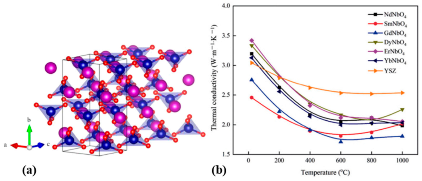
3.2.3. Rare-Earth Niobates

Rare-earth niobate is a new ceramic material with an integrated structure and function that has attracted considerable attention. The basic crystal structures are pyrochlore with a defective fluorite structure (RE3NbO7) and perovskite structure (RENbO4) (Figure 38a). Perovskite rare-earth niobate RENbO4 ceramics have a similar crystal structure to RETaO4 ceramics and have the same potential as a new TBC material. RENbO4 exhibits a lower thermal conductivity than YSZ at > 200 °C (Figure 38b), with a range of 1.80–2.26 W/m·K at 1000 °C. The low thermal conductivity of RENbO4 is due to the large chemical inhomogeneity in terms of the charge difference between cations and a fluctuating bonding length. Rare-earth niobate has a ferroelastic structure (Figure 39), which allows for increased fracture toughness.

3.2.4. Other Materials

Perovskite-oxides (ABO3, where A = Ba, Sr, and B = Zr, Ti, Hf) can accommodate a wide range of ions in the solid solution, including those with large atomic masses, and are considered potential ceramic materials for TBCs because of their excellent mechanical properties. CaZrO3 has low thermal conductivity and cost, but the thermal expansion and melting point coefficients are lower than YSZ, which can be applied to some lower-temperature environments [197,212,213,214]. RAAl11O19 is an alumina-based coating material with a low sintering rate and good thermal stability, which can be used in environments above 1200 °C [215]. However, it is unsuitable for the EB-PVD method preparation due to the low deposition efficiency and amorphous body [215]. In summary, poor fracture toughness and low CTE are the main reasons limiting the use of advanced materials for TC (Figure 40). Several studies have designed different structures with different materials and tried to overcome these problems.

3.2.5. YSZ-Based Double Ceramic Layer

A double ceramic layer (DCL) structure is an effective means to overcome the poor fracture toughness of ceramic materials for advanced TBCs. The DCL structure is based on depositing a layer of advanced ceramic material on YSZ. A DCL is a better solution to improve the thermal insulation ability and bond strength of the coating simultaneously. The bottom layer of YSZ enhances the fracture toughness of the coating and provides a transition adjustment for the thermal expansion mismatch between the advanced material and substrate. The advanced material used as the top layer reduces the thermal conductivity of the coating and enhances the thermal insulation performance of the coating.
Cheng et al. [217,218] prepared La2Zr2O7 (LZO)/YSZ DCL TBCs with different layer thickness ratios and different elastic moduli by APS (Figure 41). Figure 41a presents a diagram of five TBC structures with different layer thickness ratios having the same thermal insulation effect, where 67 μm LZO and 100 μm YSZ have the same thermal insulation effect. Thus, advanced ceramic materials help reduce the thickness of ceramic layers while maintaining the same thermal insulation performance. Figure 42a shows the cross-sectional microstructures of five TBCs, where the coatings of two materials have similar microstructures because of the same preparation method. Under the thermal gradient cycling test, 4Y/1L and 3Y/2L exhibited higher lifetimes than the conventional YSZ coating (Figure 43a). As the percentage of LZO increased, the coating failure shifted from the TC/BC interface to the LZO/YSZ interface and finally to within the LZO layer because of the lower CTE and poorer fracture toughness of LZO. Subsequently, the combination of 3Y/2L was optimized, and LZO layers with different elastic moduli were prepared (Figure 41b). LZO with different elastic moduli was achieved by varying the spraying distance to prepare different porosity structures (Figure 42c−e). By further optimization of the microstructure, the TBC lifetimes of the 3Y/2L combination were all higher than those of the conventional YSZ. The thermal gradient cycle lifetimes were, in descending order, 3 Low LZO/2Y > 3 Middle LZO/2Y > 3 High LZO/2Y > 5YSZ (Figure 43b). Chen et al. [219] examined the thermal cycling failure of LaMgAl11O19 (LMA)/YSZ DCL TBC with YSZ and LMA monolayer systems. The results showed that the LMA/YSZ DCL TBCs, which overcame the thermal mismatch between the LMA TC and substrate, have better strain tolerance and thermal cycling life than the single-layer YSZ and LMA coatings. Therefore, DCL TBCs can improve the thermal insulation while enhancing the lifetime.

3.3. Nano- and Composite-Structured Coatings

3.3.1. Nanostructured Coatings

The mechanical properties of materials can be enhanced significantly when the grain size of a material is transformed from the microscale to the nanoscale [220,221,222]. The lifetime of nanostructured YSZ TBCs has been extended by 50–100% compared to conventional PS YSZ TBCs [223,224]. In addition, the resistance to sintering and oxidation is enhanced significantly [225], and the degradation of the thermal insulation properties is less than 50% [226,227]. Therefore, nanostructured coatings have become a potential next step in developing TBCs.
PS should be carried out by choosing the appropriate spraying parameters [228,229] to achieve a particle state where complete and partial melting coexist and preserve the nanoscale of the raw powder [230]. Thus, the nanostructured PS-TBCs have a bimodal structure, which is manifested as a conventional lamellar structure with nanozones contained in it [225,231]. In nanostructured TBCs, the lamellar zones are relatively dense with anisotropic structures, whereas the nanozones have a higher surface area with an isotropic loose structure [232]. Therefore, the nanozones have a different sintering behavior from the lamellar zone.
Figure 44 shows the microstructural evolution of conventional PS-TBCs and nanostructured TBCs during thermal exposure [233]. After thermal exposure, the initial lamellar multi-scale pore structure of conventional TBCs subsided, and the coating became much denser due to sintering. However, for nanostructured TBCs, the porous nanostructured agglomerates within the nanozones have a higher driving force for sintering-induced densification than the lamellar zones. Therefore, rapid densification of the nanozones led to the formation of coarse voids.
Figure 45 shows the changes in the elastic modulus and thermal conductivity as a function of thermal exposure [233]. The changes in both are nonlinear throughout the heat exposure phase. This is consistent with that mentioned in Section 2.3. However, for nanostructured TBCs, the degree of the increase in performance is smaller than that for conventional TBCs. The main reason for this is the contribution of the newly formed coarse pores to the thermal conductivity and strain tolerance. A previous study reported that nanostructured TBCs could achieve longer lifetimes during thermal shock tests [223].
Briefly, nanostructured TBCs are used to maintain the strain tolerance of a coating by comparing the nanozones. The original 2D pores in the lamellar zone still subside. Further efforts should be made to control the newly formed pore orientation, which contributes to the thermal and mechanical properties of the coatings.

3.3.2. Composite Structured Coatings

Composite structured TBCs are similar to nanostructured TBCs because both have a bimodal structure, and the spontaneous formation of pores occurs during thermal exposure. However, composite structures can be tailored to a newly formed pore orientation to improve strain tolerance and thermal insulation.
Li et al. [234] designed three TBCs (Figure 46) by tailoring the morphology of the inclusions to obtain a preferred orientation of the insulating pores, namely, conventional TBCs (Mono-TBCs), composite TBCs with isotropic nano-inclusions (composite-TBC-1), and composite TBCs with anisotropic nano-inclusions (composite-TBC-2). Composite-TBC-1 is nanostructured TBCs and composite-TBC-2 is formed by stacking alternately sprayed dense splits and nano-powder heaps with 2D morphology that has a large aspect ratio from the cross-section.
Figure 47 shows the evolution of the cross-sectional microstructures of the three TBCs during thermal exposure [234]. All TBCs underwent severe sintering, particularly in conventional TBCs, where the 2D pores almost disappeared. These nanostructures form coarse pores after thermal exposure. The difference is that the newly formed pores in composite TBCs-2 have a perpendicular orientation to the heat flow and have 2D pore characteristics. The 2D pores play a significant role in preventing heat flux. The 2D pore density of composite-TBC-2 was consistently higher than that of composite-TBC-1 during heat exposure. Thus, the thermal insulation performance was better (Figure 48).
In conclusion, for the application of composite TBCs, a bimodal structural coating will reduce the increase in thermal conductivity and elastic modulus considerably when exposed to high temperatures by counteracting the densification effect through differential sintering. However, the newly formed pores may reduce the cohesion of the coating. Hence, further investigation is needed.

4. Outlook

Thermal barrier coating technology is an indispensable technology for manufacturing high-performance engines in the future. In recent years, researchers have made significant progress in the research of thermal barrier coating preparation technology, but there are still problems in the contradiction between coating performance and equipment cost and process cost, as well as the limitation of application scope. Future research should focus on the following areas: (i) improved PS-TBC deposition process and post-treatment process to achieve porous TBC structures with segmented cracks, and enhanced thermal insulation and strain tolerance of the coating to increase the service life of TBCs; (ii) diversified composite TBC preparation processes, such as plasma enhanced chemical vapor deposition (PE-CVD) and laser CVD, to improve production efficiency and reduce process costs; and (iii) exploring new rare-earth, doped-ceramic material systems and nanoscale ceramic material sizes to improve thermal insulation and bonding of coatings.

5. Conclusions

TBCs provide essential thermal protection for gas turbines, and higher thermal insulation and durability of TBCs are required to meet the development of efficient industrial levels. Therefore, this paper reviewed the development and synergistic design of advanced materials and coating structures for TBCs based on a comprehensive understanding of the factors influencing coating thermal insulation and the mechanisms of heat transfer and degradation. The main conclusions are as follows.
(i) The coating thickness intuitively affects the thermal insulation; the TBC thickness increased by 0.2 mm, which results in a decrease in the maximum blade temperature of approximately 40 K. However, it also leads to large thermal gradients and high elastic strain energy, which can drive cracks, leading to coating delamination. Functional gradients and TTBCs with segmented cracks can solve this problem. Functional gradient TTBCs improve the fracture toughness near the TC/BC interface. TTBCs with segmented cracks increase the compliance of the coating, and segmented crack densities between 2.38 and 4.76 mm−1 contribute to the thermal shock resistance of the coating.
(ii) Advanced TBC materials, such as rare-earth zirconates, rare-earth tantalates, and rare-earth niobates, have low thermal conductivity. The rare-earth zirconates produce a YSZ-based DCL structure required for their application because of their low fracture toughness and CTE drawbacks. Choosing the correct thickness ratio in the DCL can increase the coating lifetime up to two times that of conventional coatings. Rare-earth tantalates and rare-earth niobates have good fracture toughness owing to their ferroelastic structure, giving them high potential in next-generation TBCs.
(iii) The porosity and aspect ratio significantly affect the thermal insulation of coatings. The decrease in porosity and aspect ratio due to sintering during thermal exposure are the main reasons for the degradation of thermal insulation. Nano- and composite-structured TBCs have unique appeal to improve the resistance of TBCs to sintering. Both are bimodal structures that resist densification by differential sintering to form new pores during thermal exposure. In composite structured TBCs, the thermal insulation of the coating is increased significantly due to the adjustable orientation of the newly formed pores.

Author Contributions

Conceptualization, L.W., J.S., H.D. and J.Y.; Data curation, L.W. and J.S.; Formal analysis, L.W., J.S. and H.D.; Investigation, J.S.; Methodology, L.W. and H.D.; Resources, L.W. and J.S.; Software, J.S. and J.Y.; Validation, H.D.; Visualization, H.D. and J.Y.; Writing–original draft, L.W. and J.S.; Writing–review & editing, J.Y. All authors have read and agreed to the published version of the manuscript.

Funding

This work was supported by the National Natural Science Foundation of China (grant number 51901181); the Young Talent fund of University Association for Science and Technology in Shaanxi, China (grant number 20200427); and the Postgraduate Innovation and Practice Ability Development Fund of Xi’an Shiyou University (grant number YCS22213133).

Institutional Review Board Statement

Not applicable.

Informed Consent Statement

Not applicable.

Data Availability Statement

The data presented in this study are available on request from the corresponding author after obtaining permission from the authorized individual.

Conflicts of Interest

The authors declare no conflict of interest.

References

  1. Clarke, D.R.; Oechsner, M.; Padture, N.P. Thermal-barrier coatings for more efficient gas-turbine engines. MRS Bull. 2012, 37, 891–898. [Google Scholar] [CrossRef]
  2. Bose, S.; DeMasi-Marcin, J. Thermal barrier coating experience in gas turbine engines at Pratt & Whitney. J. Therm. Spray Technol. 1997, 6, 99–104. [Google Scholar] [CrossRef]
  3. Miller, R.A. Thermal barrier coatings for aircraft engines: History and directions. J. Therm. Spray Technol. 1997, 6, 35–42. [Google Scholar] [CrossRef]
  4. Padture, N.P.; Gell, M.; Jordan, E.H. Thermal barrier coatings for gas-turbine engine applications. Science 2002, 296, 280–284. [Google Scholar] [CrossRef] [PubMed]
  5. Chen, H.; Zhang, C.; Liu, Y.; Song, P.; Li, W.; Yang, G.; Liu, B. Recent progress in thermal/environmental barrier coatings and their corrosion resistance. Rare Met. 2020, 39, 498–512. [Google Scholar] [CrossRef]
  6. Padture, N.P. Advanced structural ceramics in aerospace propulsion. Nat. Mater. 2016, 15, 804–809. [Google Scholar] [CrossRef] [PubMed]
  7. Schulz, U.; Leyens, C.; Fritscher, K.; Peters, M.; Saruhan-Brings, B.; Lavigne, O.; Dorvaux, J.-M.; Poulain, M.; Mévrel, R.; Caliez, M. Some recent trends in research and technology of advanced thermal barrier coatings. Aerosp. Sci. Technol. 2003, 7, 73–80. [Google Scholar] [CrossRef]
  8. Wei, Z.Y.; Cai, H.N.; Zhao, S.D.; Li, G.R.; Zhang, W.W.; Tahir, A. Dynamic multi-crack evolution and coupling TBC failure together induced by continuous TGO growth and ceramic sintering. Ceram. Int. 2022, 48, 15913–15924. [Google Scholar] [CrossRef]
  9. Meng, G.-H.; Zhang, B.-Y.; Liu, H.; Yang, G.-J.; Xu, T.; Li, C.-X.; Li, C.-J. Vacuum heat treatment mechanisms promoting the adhesion strength of thermally sprayed metallic coatings. Surf. Coat. Technol. 2018, 344, 102–110. [Google Scholar] [CrossRef]
  10. Meng, G.-H.; Zhang, B.-Y.; Liu, H.; Yang, G.-J.; Xu, T.; Li, C.-X.; Li, C.-J. Highly oxidation resistant and cost effective MCrAlY bond coats prepared by controlled atmosphere heat treatment. Surf. Coat. Technol. 2018, 347, 54–65. [Google Scholar] [CrossRef]
  11. Yang, G.-J.; Xiang, X.-D.; Xing, L.-K.; Li, D.-J.; Li, C.-J.; Li, C.-X. Isothermal oxidation behavior of NiCoCrAlTaY coating deposited by high velocity air-fuel spraying. J. Therm. Spray Technol. 2012, 21, 391–399. [Google Scholar] [CrossRef]
  12. Zhu, C.; Wang, Y.G.; An, L.N.; Javed, A.; Xiao, P.; Liang, G.Y. Microstructure and oxidation behavior of conventional and pseudo graded NiCrAlY/YSZ thermal barrier coatings produced by supersonic air plasma spraying process. Surf. Coat. Technol. 2015, 272, 121–128. [Google Scholar] [CrossRef]
  13. Li, G.R.; Tang, C.H.; Yang, G.J. Dynamic-stiffening-induced aggravated cracking behavior driven by metal-substrate-constraint in a coating/substrate system. J. Mater. Sci. Technol. 2021, 65, 154–163. [Google Scholar] [CrossRef]
  14. Peng, X.M.; Wu, A.R.; Dong, L.J.; Tao, Y.R.; Gao, W.G.; Zhou, X.L. Stability of NiCrAlY coating/titanium alloy system under pure thermal exposure. Rare Met. 2017, 36, 7. [Google Scholar] [CrossRef]
  15. Meng, G.-H.; Liu, H.; Liu, M.-J.; Xu, T.; Yang, G.-J.; Li, C.-X.; Li, C.-J. Large-grain α-Al2O3 enabling ultra-high oxidation-resistant MCrAlY bond coats by surface pre-agglomeration treatment. Corros. Sci. 2020, 163, 108275. [Google Scholar] [CrossRef]
  16. Meng, G.H.; Liu, H.; Xu, P.Y.; Li, G.R.; Xu, T.; Yang, G.J.; Li, C.J. Superior oxidation resistant MCrAlY bond coats prepared by controlled atmosphere heat treatment. Corros. Sci. 2020, 170, 108653. [Google Scholar] [CrossRef]
  17. Mehboob, G.; Liu, M.-J.; Xu, T.; Hussain, S.; Mehboob, G.; Tahir, A. A review on failure mechanism of thermal barrier coatings and strategies to extend their lifetime. Ceram. Int. 2020, 46, 8497–8521. [Google Scholar] [CrossRef]
  18. Liu, B.; Liu, Y.; Zhu, C.; Xiang, H.; Chen, H.; Sun, L.; Gao, Y.; Zhou, Y. Advances on strategies for searching for next generation thermal barrier coating materials. J. Mater. Sci. Technol. 2019, 35, 833–851. [Google Scholar] [CrossRef]
  19. Zhang, W.-W.; Li, G.-R.; Zhang, Q.; Yang, G.-J. Comprehensive damage evaluation of localized spallation of thermal barrier coatings. J. Adv. Ceram. 2017, 6, 230–239. [Google Scholar] [CrossRef]
  20. Liu, Q.; Huang, S.; He, A. Composite ceramics thermal barrier coatings of yttria stabilized zirconia for aero-engines. J. Mater. Sci. Technol. 2019, 35, 2814–2823. [Google Scholar] [CrossRef]
  21. Zhang, B.; Cheng, L.; Lu, Y.; Zhang, Q. Scalable preparation of graphene reinforced Zirconium diboride composites with strong dynamic response. Carbon 2018, 139, 1020–1026. [Google Scholar] [CrossRef]
  22. Cipitria, A.; Golosnoy, I.O.; Clyne, T.W. A sintering model for plasma-sprayed zirconia thermal barrier coatings. Part II: Coatings bonded to a rigid substrate. Acta Mater. 2009, 57, 993–1003. [Google Scholar] [CrossRef]
  23. Li, G.R.; Xie, H.; Yang, G.J.; Liu, G.; Li, C.X.; Li, C.J. A comprehensive sintering mechanism for TBCs-Part I: An overall evolution with two-stage kinetics. J. Am. Ceram. Soc. 2017, 100, 2176–2189. [Google Scholar] [CrossRef]
  24. Darolia, R. Thermal barrier coatings technology: Critical review, progress update, remaining challenges and prospects. Int. Mater. Rev. 2013, 58, 315–348. [Google Scholar] [CrossRef]
  25. Peters, M.; Leyens, C.; Schulz, U.; Kaysser, W.A. EB-PVD thermal barrier coatings for aeroengines and gas turbines. Adv. Eng. Mater. 2001, 3, 193–204. [Google Scholar] [CrossRef]
  26. Yu, Z.-Y.; Wei, L.-L.; Guo, X.-Y.; Zhang, B.-P.; He, Q.; Guo, H.-B. Microstructural evolution, mechanical properties and degradation mechanism of PS-PVD quasi-columnar thermal barrier coatings exposed to glassy CMAS deposits. Rare Met. 2018, 2018., 1–12. [Google Scholar] [CrossRef]
  27. Deng, Z.-Q.; Mao, J.; Liu, M.; Deng, C.-M.; Ma, J.-T. Regional characteristic of 7YSZ coatings prepared by plasma spray-physical vapor deposition technique. Rare Met. 2018, 40, 3308–3315. [Google Scholar] [CrossRef]
  28. Chen, Q.Y.; Peng, X.-Z.; Yang, G.-J.; Li, C.-X.; Li, C.-J. Characterization of plasma jet in plasma spray-physical vapor deposition of YSZ using a <80 kW shrouded torch based on optical emission spectroscopy. J. Therm. Spray Technol. 2015, 24, 1038–1045. [Google Scholar] [CrossRef]
  29. Liu, M.-J.; Zhang, K.-J.; Zhang, Q.; Zhang, M.; Yang, G.-J.; Li, C.-X.; Li, C.-J. Thermodynamic conditions for cluster formation in supersaturated boundary layer during plasma spray-physical vapor deposition. Appl. Surf. Sci. 2019, 471, 950–959. [Google Scholar] [CrossRef]
  30. Liu, M.-J.; Zhang, M.; Zhang, Q.; Yang, G.-J.; Li, C.-X.; Li, C.-J. Gaseous material capacity of open plasma jet in plasma spray-physical vapor deposition process. Appl. Surf. Sci. 2018, 428, 877–884. [Google Scholar] [CrossRef]
  31. Tingaud, O.; Grimaud, A.; Denoirjean, A.; Montavon, G.; Rat, V.; Coudert, J.F.; Fauchais, P.; Chartier, T. Suspension plasma-sprayed alumina coating structures: Operating parameters versus coating architecture. J. Therm. Spray Technol. 2008, 17, 662–670. [Google Scholar] [CrossRef]
  32. Kumar, N.; Gupta, M.; Mack, D.E.; Mauer, G.; Vaßen, R. Columnar thermal barrier coatings produced by different thermal spray processes. J. Therm. Spray Technol. 2021, 30, 1437–1452. [Google Scholar] [CrossRef]
  33. Kumar, A.; Nayak, S.K.; Bijalwan, P.; Dutta, M.; Banerjee, A.; Laha, T. Optimization of mechanical and corrosion properties of plasma sprayed low-chromium containing Fe-based amorphous/nanocrystalline composite coating. Surf. Coat. Technol. 2019, 370, 255–268. [Google Scholar] [CrossRef]
  34. Xie, S.; Song, C.; Yu, Z.; Liu, S.; Lapostolle, F.; Klein, D.; Deng, C.; Liu, M.; Liao, H. Effect of environmental pressure on the microstructure of YSZ thermal barrier coating via suspension plasma spraying. J. Eur. Ceram. Soc. 2021, 41, 535–543. [Google Scholar] [CrossRef]
  35. Feuerstein, A.; Knapp, J.; Taylor, T.; Ashary, A.; Bolcavage, A.; Hitchman, N. Technical and economical aspects of current thermal barrier coating systems for gas turbine engines by thermal spray and EBPVD: A review. J. Therm. Spray Technol. 2008, 17, 199–213. [Google Scholar] [CrossRef]
  36. Christensen, R.; Lipkin, D.; Clarke, D.; Murphy, K.s. Non-destructive evaluation of oxidation stresses through thermal barrier coatings using Cr3+ piezospectroscopy. Appl. Phys. Lett. 1996, 69, 3754–3756. [Google Scholar] [CrossRef]
  37. Ganvir, A.; Curry, N.; Markocsan, N.; Nylén, P.; Toma, F.-L. Comparative study of suspension plasma sprayed and suspension high velocity oxy-fuel sprayed YSZ thermal barrier coatings. Surf. Coat. Technol. 2015, 268, 70–76. [Google Scholar] [CrossRef]
  38. Mauer, G.; Hospach, A.; Zotov, N.; Vaßen, R. Process conditions and microstructures of ceramic coatings by gas phase deposition based on plasma spraying. J. Therm. Spray Technol. 2012, 22, 83–89. [Google Scholar] [CrossRef]
  39. Zhang, B.; Song, W.; Wei, L.; Xiu, Y.; Xu, H.; Dingwell, D.B.; Guo, H. Novel thermal barrier coatings repel and resist molten silicate deposits. Scr. Mater. 2019, 163, 71–76. [Google Scholar] [CrossRef]
  40. Kitamura, J.; Tang, Z.; Mizuno, H.; Sato, K.; Burgess, A. Structural, mechanical and erosion properties of yttrium oxide coatings by axial suspension plasma spraying for electronics applications. J. Therm. Spray Technol. 2011, 20, 170–185. [Google Scholar] [CrossRef]
  41. Xie, H.; Yingchun, X.; Yang, G.-J.; Li, C.-X.; Li, C.-J. Modeling thermal conductivity of thermally sprayed coatings with intrasplat cracks. J. Therm. Spray Technol. 2013, 22, 1328–1336. [Google Scholar] [CrossRef]
  42. Mondal, K.; Nunẽz, L.; Iii, C.; Downey, I.; Van Rooyen, I. Thermal barrier coatings overview: Design, manufacturing, and applications in high-temperature industries. Ind. Eng. Chem. Res. 2021, 60. [Google Scholar] [CrossRef]
  43. Miller, R.A. Current status of thermal barrier coatings—An overview. Surf. Coat. Technol. 1987, 30, 1–11. [Google Scholar] [CrossRef]
  44. Swadźba, R.; Wiedermann, J.; Swadźba, L.; Hetmańczyk, M.; Witala, B.; Schulz, U.; Jung, T. High temperature oxidation of EB-PVD TBCs on Pt-diffused single crystal Ni superalloy. Surf. Coat. Technol. 2014, 260, 2–8. [Google Scholar] [CrossRef]
  45. Lima, R.S. Porous APS YSZ TBC manufactured at high powder feed rate (100 g/min) and deposition efficiency (70%): Microstructure, bond strength and thermal gradients. J. Therm. Spray Technol. 2022, 31, 396–414. [Google Scholar] [CrossRef]
  46. Izadinia, M.; Soltani, R.; Sohi, M.H. Effect of segmented cracks on TGO growth and life of thick thermal barrier coating under isothermal oxidation conditions. Ceram. Int. 2020, 46, 7475–7481. [Google Scholar] [CrossRef]
  47. Steffens, H.D.; Babiak, Z.; Gramlich, M. Some aspects of thick thermal barrier coating lifetime prolongation. J. Therm. Spray Technol. 1999, 8, 517–522. [Google Scholar] [CrossRef]
  48. Li, L.; Zhang, W. Thickness effects on the delamination energy release rate of thermal barrier coating subjected to thermo-mechanical loads. Int. J. Solids Struct. 2022, 254, 111937. [Google Scholar] [CrossRef]
  49. Samadi, H. A Thick Multilayer Thermal Barrier Coating: Design, Deposition, and Internal Stresses; University of Toronto: Toronto, ON, Canada, 2010. [Google Scholar]
  50. Guo, H.B.; Vaßen, R.; Stöver, D. Atmospheric plasma sprayed thick thermal barrier coatings with high segmentation crack density. Surf. Coat. Technol. 2004, 186, 353–363. [Google Scholar] [CrossRef]
  51. Sundaram, S.; Lipkin, D.M.; Johnson, C.A.; Hutchinson, J.W. The influence of transient thermal gradients and substrate constraint on delamination of thermal barrier coatings. J. Appl. Mech. 2012, 80. [Google Scholar] [CrossRef]
  52. Mohammadzaki Goudarzi, Z.; Valefi, Z.; Zamani, P. Effect of functionally graded structure design on durability and thermal insulation capacity of plasma-sprayed thick thermal barrier coating. Ceram. Int. 2021, 47, 34361–34379. [Google Scholar] [CrossRef]
  53. Jadhav, A.D. Processing, Characterization, and Properties of Some Novel Thermal Barrier Coatings. Ph.D. Thesis, The Ohio State University, Columbus, OH, USA, 2007. [Google Scholar]
  54. Liang, L.H.; Liu, X.H.; Chen, L.F.; Wei, Y.G. Effect of ceramic coating thickness on fracture behaviour of coating structure under thermal shock cycles. Ceram. Int. 2022, 48, 11435–11444. [Google Scholar] [CrossRef]
  55. Vo, D.-T.; Mai, T.D.; Kim, B.; Ryu, J. Numerical study on the influence of coolant temperature, pressure, and thermal barrier coating thickness on heat transfer in high-pressure blades. Int. J. Heat Mass Transf. 2022, 189, 122715. [Google Scholar] [CrossRef]
  56. Donachie, M.J.; Donachie, S.J. Superalloys: A Technical Guide; ASM International: Almere, The Netherlands, 2002. [Google Scholar]
  57. Golosnoy, I.O.; Cipitria, A.; Clyne, T.W. Heat transfer through plasma-sprayed thermal barrier coatings in gas turbines: A review of recent work. J. Therm. Spray Technol. 2009, 18, 809–821. [Google Scholar] [CrossRef]
  58. Grimvall, G. Chapter 7—Thermal properties of harmonic lattice vibrations. In Thermophysical Properties of Materials; Grimvall, G., Ed.; Elsevier Science B.V.: Amsterdam, The Netherlands, 1999; pp. 112–135. [Google Scholar]
  59. Klemens, P.G. Thermal conductivity and lattice vibrational modes. In Solid State Physics; Seitz, F., Turnbull, D., Eds.; Academic Press: Cambridge, MA, USA, 1958; Volume 7, pp. 1–98. [Google Scholar]
  60. Winter, M.R.; Clarke, D.R. Oxide materials with low thermal conductivity. J. Am. Ceram. Soc. 2007, 90, 533–540. [Google Scholar] [CrossRef]
  61. Wang, L.-S.; Tang, C.-H.; Dong, H.; Li, G.-R.; Yang, G.-J. Dominant effects of 2D pores on mechanical behaviors of plasma sprayed ceramic coatings during thermal exposure. Ceram. Int. 2020, 46, 6774–6781. [Google Scholar] [CrossRef]
  62. Litovsky, E.; Shapiro, M.; Shavit, A. Gas pressure and temperature dependences of thermal conductivity of porous ceramic materials: Part 2, refractories and ceramics with porosity exceeding 30%. J. Am. Ceram. Soc. 1996, 79, 1366–1376. [Google Scholar] [CrossRef]
  63. McPherson, R. A model for the thermal conductivity of plasma-sprayed ceramic coatings. Thin Solid Film. 1984, 112, 89–95. [Google Scholar] [CrossRef]
  64. Hass, D.D.; Slifka, A.J.; Wadley, H.N.G. Low thermal conductivity vapor deposited zirconia microstructures. Acta Mater. 2001, 49, 973–983. [Google Scholar] [CrossRef]
  65. Khor, K.A.; Gu, Y.W. Thermal properties of plasma-sprayed functionally graded thermal barrier coatings. Thin Solid Film. 2000, 372, 104–113. [Google Scholar] [CrossRef]
  66. Wei, S.; Fu-chi, W.; Qun-bo, F.; Dan, H.; Zhuang, M. Proposal of new expressions for effects of splat interfaces and defects on effective properties of thermal barrier coatings. Surf. Coat. Technol. 2010, 204, 3376–3381. [Google Scholar] [CrossRef]
  67. Wei, S.; Fu-chi, W.; Qun-Bo, F.; Zhuang, M. Effects of defects on the effective thermal conductivity of thermal barrier coatings. Appl. Math. Model. 2012, 36, 1995–2002. [Google Scholar] [CrossRef]
  68. Wu, J.; Wei, X.; Padture, N.P.; Klemens, P.G.; Gell, M.; García, E.; Miranzo, P.; Osendi, M.I. Low-thermal-conductivity rare-earth zirconates for potential thermal-barrier-coating applications. J. Am. Ceram. Soc. 2002, 85, 3031–3035. [Google Scholar] [CrossRef]
  69. Neuer, G.; Steffens, H.D.; Brandl, W.; Babiak, Z.; Brandt, R. Some aspects of properties design of plasma-sprayed thermal barrier coatings. PMI. Powder Metall. Int. 1991, 23, 108–111. [Google Scholar]
  70. Long, Y.; Wang, Y.; Chen, X.; Sang, R. Influence of crack features on heat transfer characteristic and cracking behaviour of APS-YSZ coating: A numerical simulation study. Ceram. Int. 2021, 47, 22209–22218. [Google Scholar] [CrossRef]
  71. Jin, X.Q.; Zhao, C.Y. Numerical investigation on the effective thermal conductivity of plasma sprayed zirconia coatings. Ceram. Int. 2015, 41, 14915–14923. [Google Scholar] [CrossRef]
  72. Golosnoy, I.O.; Tsipas, S.; Clyne, B. An analytical model for simulation of heat flow in plasma-sprayed thermal barrier coatings. J. Therm. Spray Technol. 2005, 14, 205–214. [Google Scholar] [CrossRef]
  73. Sun, F.; Fan, X.; Zhang, T.; Jiang, P.; Yang, J. Numerical analysis of the influence of pore microstructure on thermal conductivity and Young’s modulus of thermal barrier coating. Ceram. Int. 2020, 46, 24326–24332. [Google Scholar] [CrossRef]
  74. Schwingel, D.; Taylor, R.; Haubold, T.; Wigren, J.; Gualco, C. Mechanical and thermophysical properties of thick PYSZ thermal barrier coatings: Correlation with microstructure and spraying parameters. Surf. Coat. Technol. 1998, 108–109, 99–106. [Google Scholar] [CrossRef]
  75. Cernuschi, F.; Bianchi, P.; Leoni, M.; Scardi, P. Thermal diffusivity/microstructure relationship in Y-PSZ thermal barrier coatings. J. Therm. Spray Technol. 1999, 8, 102–109. [Google Scholar] [CrossRef]
  76. Lu, T.J.; Levi, C.G.; Wadley, H.N.G.; Evans, A.G. Distributed porosity as a control parameter for oxide thermal barriers made by physical vapor deposition. J. Am. Ceram. Soc. 2001, 84, 2937–2946. [Google Scholar] [CrossRef]
  77. Dutton, R.; Wheeler, R.; Ravichandran, K.S.; An, K. Effect of heat treatment on the thermal conductivity of plasma-sprayed thermal barrier coatings. J. Therm. Spray Technol. 2000, 9, 204–209. [Google Scholar] [CrossRef]
  78. Sevostianov, I.; Kachanov, M. Elastic and conductive properties of plasma-sprayed ceramic coatings in relation to their microstructure: An overview. J. Therm. Spray Technol. 2009, 18, 822–834. [Google Scholar] [CrossRef]
  79. Clarke, D.R. Materials selection guidelines for low thermal conductivity thermal barrier coatings. Surf. Coat. Technol. 2003, 163–164, 67–74. [Google Scholar] [CrossRef]
  80. Wang, L.; Wang, Y.; Sun, X.G.; He, J.Q.; Pan, Z.Y.; Zhou, Y.; Wu, P.L. Influence of pores on the thermal insulation behavior of thermal barrier coatings prepared by atmospheric plasma spray. Mater. Des. 2011, 32, 36–47. [Google Scholar] [CrossRef]
  81. Yang, M.; Zhu, Y.; Wang, X.; Guo, S.; Hu, J.; Zhao, L.; Chu, Y. Effect of five kinds of pores shape on thermal stress properties of thermal barrier coatings by finite element method. Ceram. Int. 2017, 43, 9664–9678. [Google Scholar] [CrossRef]
  82. Wei, Z.-Y.; Wang, L.-S.; Cai, H.-N.; Li, G.-R.; Chen, X.-F.; Zhang, W.-X. Dominant effect of oriented 2D pores on heat flux in lamellar structured thermal barrier coatings. Ceram. Int. 2019, 45, 17029–17039. [Google Scholar] [CrossRef]
  83. Li, G.-R.; Yang, G.-J.; Li, C.-X.; Li, C.-J. Force transmission and its effect on structural changes in plasma-sprayed lamellar ceramic coatings. J. Eur. Ceram. Soc. 2017, 37, 2877–2888. [Google Scholar] [CrossRef]
  84. Hu, L.; Wang, C.-A.; Hu, Z.; Lu, S.; Sun, C.; Huang, Y. Porous yttria-stabilized zirconia ceramics with ultra-low thermal conductivity. Part II: Temperature dependence of thermophysical properties. J. Mater. Sci. 2011, 46, 623–628. [Google Scholar] [CrossRef]
  85. Kocjan, A.; Shen, Z. Colloidal processing and partial sintering of high-performance porous zirconia nanoceramics with hierarchical heterogeneities. J. Eur. Ceram. Soc. 2013, 33, 3165–3176. [Google Scholar] [CrossRef]
  86. Cernuschi, F.; Golosnoy, I.O.; Bison, P.; Moscatelli, A.; Vassen, R.; Bossmann, H.P.; Capelli, S. Microstructural characterization of porous thermal barrier coatings by IR gas porosimetry and sintering forecasts. Acta Mater. 2013, 61, 248–262. [Google Scholar] [CrossRef]
  87. Shi, H.; Zhao, C.Y.; Wang, B.X. Modeling the thermal radiation properties of thermal barrier coatings based on a random generation algorithm. Ceram. Int. 2016, 42, 9752–9761. [Google Scholar] [CrossRef]
  88. Ravichandran, K.S.; An, K.; Dutton, R.E.; Semiatin, S.L. Thermal conductivity of plasma-sprayed monolithic and multilayer coatings of alumina and yttria-stabilized zirconia. J. Am. Ceram. Soc. 1999, 82, 673–682. [Google Scholar] [CrossRef]
  89. Bertrand, G.; Bertrand, P.; Roy, P.; Rio, C.; Mevrel, R. Low conductivity plasma sprayed thermal barrier coating using hollow psz spheres: Correlation between thermophysical properties and microstructure. Surf. Coat. Technol. 2008, 202, 1994–2001. [Google Scholar] [CrossRef]
  90. Zhang, X.; Kulczyk-Malecka, J.; Carr, J.; Xiao, P.; Withers, P.J. 3D characterization of porosity in an air plasma-sprayed thermal barrier coating and its effect on thermal conductivity. J. Am. Ceram. Soc. 2018, 101, 2482–2492. [Google Scholar] [CrossRef]
  91. Wang, Y.; Liu, H.; Ling, X.; Weng, Y. Effects of pore microstructure on the effective thermal conductivity of thermal barrier coatings. Appl. Therm. Eng. 2016, 102, 234–242. [Google Scholar] [CrossRef]
  92. Boissonnet, G.; Bonnet, G.; Pasquet, A.; Bourhila, N.; Pedraza, F. Evolution of thermal insulation of plasma-sprayed thermal barrier coating systems with exposure to high temperature. J. Eur. Ceram. Soc. 2019, 39, 2111–2121. [Google Scholar] [CrossRef]
  93. Chi, W.; Sampath, S.; Wang, H. Microstructure–thermal conductivity relationships for plasma-sprayed yttria-stabilized zirconia coatings. J. Am. Ceram. Soc. 2008, 91, 2636–2645. [Google Scholar] [CrossRef]
  94. Kulkarni, A.; Wang, Z.; Nakamura, T.; Sampath, S.; Goland, A.; Herman, H.; Allen, J.; Ilavsky, J.; Long, G.; Frahm, J.; et al. Comprehensive microstructural characterization and predictive property modeling of plasma-sprayed zirconia coatings. Acta Mater. 2003, 51, 2457–2475. [Google Scholar] [CrossRef]
  95. Pia, G.; Casnedi, L.; Sanna, U. Porosity and pore size distribution influence on thermal conductivity of yttria-stabilized zirconia: Experimental findings and model predictions. Ceram. Int. 2016, 42, 5802–5809. [Google Scholar] [CrossRef]
  96. Cernuschi, F.; Lorenzoni, L.; Ahmaniemi, S.; Vuoristo, P.; Mäntylä, T. Studies of the sintering kinetics of thick thermal barrier coatings by thermal diffusivity measurements. J. Eur. Ceram. Soc. 2005, 25, 393–400. [Google Scholar] [CrossRef]
  97. Tan, Y.; Srinivasan, V.; Nakamura, T.; Sampath, S.; Bertrand, P.; Bertrand, G. Optimizing compliance and thermal conductivity of plasma sprayed thermal barrier coatings via controlled powders and processing strategies. J. Therm. Spray Technol. 2012, 21, 950–962. [Google Scholar] [CrossRef]
  98. Tan, Y.; Longtin, J.P.; Sampath, S.; Wang, H. Effect of the starting microstructure on the thermal properties of as-sprayed and thermally exposed plasma-sprayed YSZ coatings. J. Am. Ceram. Soc. 2009, 92, 710–716. [Google Scholar] [CrossRef]
  99. Curry, N.; Markocsan, N.; Östergren, L.; Li, X.-H.; Dorfman, M. Evaluation of the lifetime and thermal conductivity of dysprosia-stabilized thermal barrier coating systems. J. Therm. Spray Technol. 2013, 22, 864–872. [Google Scholar] [CrossRef]
  100. Ercan, B.; Bowman, K.J.; Trice, R.W.; Wang, H.; Porter, W. Effect of initial powder morphology on thermal and mechanical properties of stand-alone plasma-sprayed 7wt.% Y2O3–ZrO2 coatings. Mater. Sci. Eng. A 2006, 435–436, 212–220. [Google Scholar] [CrossRef]
  101. Wang, K.; Peng, H.; Guo, H.B.; Gong, S.K. Effect of sintering on thermal conductivity and thermal barrier effects of thermal barrier coatings. Chin. J. Aeronaut. 2012, 25, 811–816. [Google Scholar] [CrossRef]
  102. Kikuchi, S.; Tezura, M.; Kimura, M.; Yamaguchi, N.; Kitaoka, S.; Kizuka, T. In situ transmission electron microscopy of high-temperature degradation of yttria-stabilized zirconia thermal barrier coatings. Scr. Mater. 2018, 150, 50–53. [Google Scholar] [CrossRef]
  103. Liu, T.; Luo, X.T.; Chen, X.; Yang, G.J.; Li, C.X.; Li, C.J. Morphology and size evolution of interlamellar two-dimensional pores in plasma-sprayed La2Zr2O7 coatings during thermal exposure at 1300 °C. J. Therm. Spray Technol. 2015, 24, 739–748. [Google Scholar] [CrossRef]
  104. Li, G.R.; Xie, H.; Yan, G.J.; Liu, G.; Li, C.X.; Li, C. A comprehensive sintering mechanism for TBCs-Part II: Multiscale multipoint interconnection-enhanced initial kinetics. J. Am. Ceram. Soc. 2017, 100, 4240–4251. [Google Scholar] [CrossRef]
  105. Cipitria, A.; Golosnoy, I.O.; Clyne, T.W. A sintering model for plasma-sprayed zirconia TBCs. Part I: Free-standing coatings. Acta Mater. 2009, 57, 980–992. [Google Scholar] [CrossRef]
  106. Cocks, A.C.F.; Fleck, N.A. Constrained sintering of an air-plasma-sprayed thermal barrier coating. Acta Mater. 2010, 58, 4233–4244. [Google Scholar] [CrossRef]
  107. Fleck, N.A.; Cocks, A. A multi-scale constitutive model for the sintering of an air-plasma-sprayed thermal barrier coating, and its response under hot isostatic pressing. J. Mech. Phys. Solids 2009, 57, 689–705. [Google Scholar] [CrossRef]
  108. Zhang, W.W.; Wei, Z.Y.; Zhang, L.Y.; Xing, Y.Z.; Zhang, Q. Low-thermal-conductivity thermal barrier coatings with a multi-scale pore design and sintering resistance following thermal exposure. Rare Met. 2020, 39, 352–367. [Google Scholar] [CrossRef]
  109. Zhang, W.-W.; Li, G.-R.; Zhang, Q.; Yang, G.-J. Multiscale pores in TBCs for lower thermal conductivity. J. Therm. Spray Technol. 2017, 26, 1183–1197. [Google Scholar] [CrossRef]
  110. Lee, P.-H.; Lee, S.-Y.; Kwon, J.-Y.; Myoung, S.-W.; Lee, J.-H.; Jung, Y.-G.; Cho, H.; Paik, U. Thermal cycling behavior and interfacial stability in thick thermal barrier coatings. Surf. Coat. Technol. 2010, 205, 1250–1255. [Google Scholar] [CrossRef]
  111. Bose, S. Chapter 7—THERMAL BARRIER COATINGS (TBCs). In High Temperature Coatings; Bose, S., Ed.; Butterworth-Heinemann: Burlington, VT, USA, 2007; pp. 155–232. [Google Scholar]
  112. Altuncu, E.; Ustel, F. Adhesion properties of the plasma spray coatings. In Proceedings of the 21st International Conference on Metallurgy and Materials, Brno, Czech Republic, 23–25 May 2012; pp. 932–938. [Google Scholar]
  113. Cao, X.Q.; Zhang, Y.F.; Zhang, J.F.; Zhong, X.H.; Wang, Y.; Ma, H.M.; Xu, Z.H.; He, L.M.; Lu, F. Failure of the plasma-sprayed coating of lanthanum hexaluminate. J. Eur. Ceram. Soc. 2008, 28, 1979–1986. [Google Scholar] [CrossRef]
  114. Wee, S.; Do, J.; Kim, K.; Lee, C.; Seok, C.; Choi, B.-G.; Choi, Y.; Kim, W. Review on mechanical thermal properties of superalloys and thermal barrier coating used in gas turbines. Appl. Sci. 2020, 10, 5476. [Google Scholar] [CrossRef]
  115. Vaßen, R.; Jarligo, M.O.; Steinke, T.; Mack, D.E.; Stöver, D. Overview on advanced thermal barrier coatings. Surf. Coat. Technol. 2010, 205, 938–942. [Google Scholar] [CrossRef]
  116. Helminiak, M.A. Factors Affecting the Lifetime of Thick Air Plasma Sprayed Thermal Barrier Coatings. Ph.D. Thesis, University of Pittsburgh, Pittsburgh, PA, USA, 2010. [Google Scholar]
  117. Zhou, C.; Wang, N.; Wang, Z.; Gong, S.; Xu, H. Thermal cycling life and thermal diffusivity of a plasma-sprayed nanostructured thermal barrier coating. Scr. Mater. 2004, 51, 945–948. [Google Scholar] [CrossRef]
  118. Guo, H.B.; Vaßen, R.; Stöver, D. Thermophysical properties and thermal cycling behavior of plasma sprayed thick thermal barrier coatings. Surf. Coat. Technol. 2005, 192, 48–56. [Google Scholar] [CrossRef]
  119. Tao, S.; Yang, J.; Shao, F.; Zhao, H.; Zhong, X.; Zhuang, Y.; Sheng, J.; Ni, J.; Li, Q.; Tao, S. Atmospheric plasma sprayed thick thermal barrier coatings: Microstructure, thermal shock behaviors and failure mechanism. Eng. Fail. Anal. 2022, 131, 105819. [Google Scholar] [CrossRef]
  120. Giolli, C.; Scrivani, A.; Rizzi, G.; Borgioli, F.; Bolelli, G.; Lusvarghi, L. Failure mechanism for thermal fatigue of thermal barrier coating systems. J. Therm. Spray Technol. 2009, 18, 223–230. [Google Scholar] [CrossRef]
  121. Scrivani, A.; Rizzi, G.; Bardi, U.; Giolli, C.; Miranda, M.M.; Ciattini, S.; Fossati, A.; Borgioli, F. Thermal fatigue behavior of thick and porous thermal barrier coatings systems. J. Therm. Spray Technol. 2007, 16, 816–821. [Google Scholar] [CrossRef]
  122. Schlichting, K.W.; Padture, N.P.; Jordan, E.H.; Gell, M. Failure modes in plasma-sprayed thermal barrier coatings. Mater. Sci. Eng. A 2003, 342, 120–130. [Google Scholar] [CrossRef]
  123. Haynes, J.A.; Ferber, M.K.; Porter, W.D.; Rigney, E.D. Characterization of alumina scales formed during isothermal and cyclic oxidation of plasma-sprayed TBC systems at 1150 °C. Oxid. Met. 1999, 52, 31–76. [Google Scholar] [CrossRef]
  124. Bobzin, K.; Zhao, L.; Ote, M.; Konigstein, T. Influence of Microstructures on Thermal Shock and Sintering Behavior of YSZ-based Thermal Barrier Coatings. Surf. Technol. 2019, 48, 28–33. [Google Scholar]
  125. Wang, L.-S.; Song, J.-B.; Dong, H.; Yao, J.-T. Sintering-induced failure mechanism of thermal barrier coatings and sintering-resistant design. Coatings 2022, 12, 1083. [Google Scholar] [CrossRef]
  126. Chen, D.; Dambra, C.; Dorfman, M. Process and properties of dense and porous vertically-cracked yttria stabilized zirconia thermal barrier coatings. Surf. Coat. Technol. 2020, 404, 126467. [Google Scholar] [CrossRef]
  127. Kawasaki, A.; Watanabe, R. Cyclic thermal fracture behavior and spallation life of PSZ/NiCrAlY functionally graded thermal barrier coatings. Mater. Sci. Forum 1999, 308–311, 402–409. [Google Scholar] [CrossRef]
  128. Rangaraj, S.; Kokini, K. Estimating the fracture resistance of functionally graded thermal barrier coatings from thermal shock tests. Surf. Coat. Technol. 2003, 173, 201–212. [Google Scholar] [CrossRef]
  129. Li, C.-J.; Li, Y.; Yang, G.-J.; Li, C.-X. A novel plasma-sprayed durable thermal barrier coating with a well-bonded YSZ interlayer between porous YSZ and bond coat. J. Therm. Spray Technol. 2012, 21, 383–390. [Google Scholar] [CrossRef]
  130. Shao, F.; Zhao, H.; Zhong, X.; Zhuang, Y.; Cheng, Z.; Wang, L.; Tao, S. Characteristics of thick columnar YSZ coatings fabricated by plasma spray-physical vapor deposition. J. Eur. Ceram. Soc. 2018, 38, 1930–1937. [Google Scholar] [CrossRef]
  131. Karger, M.; Vaßen, R.; Stöver, D. Atmospheric plasma sprayed thermal barrier coatings with high segmentation crack densities: Spraying process, microstructure and thermal cycling behavior. Surf. Coat. Technol. 2011, 206, 16–23. [Google Scholar] [CrossRef]
  132. Scrivani, A.; Rizzi, G.; Berndt, C.C. Enhanced thick thermal barrier coatings that exhibit varying porosity. Mater. Sci. Eng. A 2008, 476, 1–7. [Google Scholar] [CrossRef]
  133. Chen, Z.; Zhang, S. Optimization design model of functional gradient thermal barrier coating material by using parallel computation. Matec. Web Conf. 2016, 67, 04007. [Google Scholar] [CrossRef]
  134. Tsukamoto, H. Design of functionally graded thermal barrier coatings based on a nonlinear micromechanical approach. Comput. Mater. Sci. 2010, 50, 429–436. [Google Scholar] [CrossRef]
  135. Bhattacharyya, A.; Maurice, D. Residual stresses in functionally graded thermal barrier coatings. Mech. Mater. 2019, 129, 50–56. [Google Scholar] [CrossRef]
  136. Wang, Y.; Han, Y.; Lin, C.; Zheng, W.; Jiang, C.; Wei, A.; Liu, Y.; Zeng, Y.; Shi, Y. Effect of spraying power on the morphology of YSZ splat and micro-structure of thermal barrier coating. Ceram. Int. 2021, 47, 18956–18963. [Google Scholar] [CrossRef]
  137. Li, C.J.; Ohmori, A. Relationships between the microstructure and properties of thermally sprayed deposits. J. Therm. Spray Technol. 2002, 11, 365–374. [Google Scholar] [CrossRef]
  138. Lv, B.; Xie, H.; Xu, R.; Fan, X.; Zhang, W.; Wang, T.J. Effects of sintering and mixed oxide growth on the interface cracking of air-plasma-sprayed thermal barrier coating system at high temperature. Appl. Surf. Sci. 2016, 360, 461–469. [Google Scholar] [CrossRef]
  139. Cai, H.; Bao, G. Crack bridging in functionally graded coatings. Int. J. Solids Struct. 1998, 35, 701–717. [Google Scholar] [CrossRef]
  140. Lv, B.; Fan, X.; Li, D.; Wang, T.J. Towards enhanced sintering resistance: Air-plasma-sprayed thermal barrier coating system with porosity gradient. J. Eur. Ceram. Soc. 2018, 38, 1946–1956. [Google Scholar] [CrossRef]
  141. Saeedi, B.; Sabour Rouh Aghdam, A.; Ebadi, A.; Khoddami, A. Influence of the thermal barrier coatings design on the oxidation behavior. J. Mater. Sci. Technol. 2009, 25, 499–507. [Google Scholar]
  142. Teja, P.K.; Ramaswamy, N.; Murthy, S.V.S.N. Thermal shock and oxidation stability tests to grade plasma sprayed functionally gradient thermal barrier coatings. Front. Adv. Mater. Res. 2019, 1, 1–11. [Google Scholar] [CrossRef]
  143. Fujii, K.; Imai, H.; Nomura, S.; Shindo, M. Functionally gradient material of silicon carbide and carbon as advanced oxidation-resistant graphite. J. Nucl. Mater. 1992, 187, 204–208. [Google Scholar] [CrossRef]
  144. Kim, S.; Go, J.; Jung, Y.-G.; Lee, J.-H. Thermoelastic characteristics in thermal barrier coatings with a graded layer between the top and bond coats. Math. Probl. Eng. 2013, 2013, 515792. [Google Scholar] [CrossRef]
  145. Khor, K.A.; Gu, Y.W. Effects of residual stress on the performance of plasma sprayed functionally graded ZrO2/NiCoCrAlY coatings. Mater. Sci. Eng. A 2000, 277, 64–76. [Google Scholar] [CrossRef]
  146. Saeedi, B.; Sabour, A.; Khoddami, A.M. Study of microstructure and thermal shock behavior of two types of thermal barrier coatings. Mater. Corros. 2009, 60, 695–703. [Google Scholar] [CrossRef]
  147. Mohammadzaki Goudarzi, Z.; Valefi, Z.; Zamani, P.; Taghi-Ramezani, S. Comparative investigation of the effect of composition and porosity gradient on thermo-mechanical properties of functionally graded thick thermal barrier coatings deposited by atmospheric plasma spraying. Ceram. Int. 2022, 48, 28800–28814. [Google Scholar] [CrossRef]
  148. Kumar, A.; Patnaik, P.C.; Chen, K. Damage assessment and fracture resistance of functionally graded advanced thermal barrier coating systems: Experimental and analytical modeling approach. Coatings 2020, 10, 474. [Google Scholar] [CrossRef]
  149. Khoddami, A.M.; Sabour, A.; Hadavi, S.M.M. Microstructure formation in thermally-sprayed duplex and functionally graded NiCrAlY/Yttria-Stabilized Zirconia coatings. Surf. Coat. Technol. 2007, 201, 6019–6024. [Google Scholar] [CrossRef]
  150. Ramaswamy, P.; Vattappara, K.; Avijit Gomes, S.; Teja Pasupuleti, K. Residual stress analysis on functionally graded 8% Y2O3-ZrO2 and NiCrAlY thermal barrier coatings. Mater. Today. Proc. 2022, 66, 1638–1644. [Google Scholar] [CrossRef]
  151. Taylor, T.A.; Appleby, D.L.; Weatherill, A.E.; Griffiths, J. Plasma-sprayed yttria-stabilized zirconia coatings: Structure-property relationships. In Metallurgical Coatings and Thin Films 1990; Sartwell, B.D., Zemel, J.N., McGuire, G.E., Bresnock, F.N., Eds.; Elsevier: Amsterdam, The Netherlands, 1990; pp. 470–480. [Google Scholar]
  152. Guo, H.; Murakami, H.; Kuroda, S. Thermal cycling behavior of plasma sprayed segmented thermal barrier coatings. Mater. Trans. 2006, 47, 306–309. [Google Scholar] [CrossRef] [Green Version]
  153. Smialek, J.L. Improved oxidation life of segmented plasma sprayed 8YSZ thermal barrier coatings. J. Therm. Spray Technol. 2004, 13, 66–75. [Google Scholar] [CrossRef]
  154. Guo, H.; Yi, W.; Lu, W.; Gong, S. Thermo-physical properties and thermal shock resistance of segmented La2Ce2O7/YSZ thermal barrier coatings. J. Therm. Spray Technol. 2009, 18, 665–671. [Google Scholar] [CrossRef]
  155. Guo, H.; Kuroda, S.; Murakami, H. Microstructures and properties of plasma-sprayed segmented thermal barrier coatings. J. Am. Ceram. Soc. 2006, 89, 1432–1439. [Google Scholar] [CrossRef]
  156. Lu, Z.; Kim, M.-S.; Myoung, S.-W.; Lee, J.-H.; Jung, Y.-G.; Kim, I.-S.; Jo, C.-Y. Thermal stability and mechanical properties of thick thermal barrier coatings with vertical type cracks. Trans. Nonferrous Met. Soc. China 2014, 24, s29–s35. [Google Scholar] [CrossRef]
  157. Bengtsson, P.; Ericsson, T.; Wigren, J. Thermal shock testing of burner cans coated with a thick thermal barrier coating. J. Therm. Spray Technol. 1998, 7, 340–348. [Google Scholar] [CrossRef]
  158. Wang, L.; Zhong, X.H.; Shao, F.; Ni, J.X.; Yang, J.S.; Tao, S.Y.; Wang, Y. What is the suitable segmentation crack density for atmospheric plasma sprayed thick thermal barrier coatings with the improved thermal shock resistance? Appl. Surf. Sci. 2018, 431, 101–111. [Google Scholar] [CrossRef]
  159. Tailor, S.; Upadhyaya, R.; Manjunath, S.Y.; Dub, A.V.; Modi, A.; Modi, S.C. Atmospheric plasma sprayed 7%-YSZ thick thermal barrier coatings with controlled segmentation crack densities and its thermal cycling behavior. Ceram. Int. 2018, 44, 2691–2699. [Google Scholar] [CrossRef]
  160. von Niessen, K.; Gindrat, M. Plasma spray-pvd: A new thermal spray process to deposit out of the vapor phase. J. Therm. Spray Technol. 2011, 20, 736–743. [Google Scholar] [CrossRef]
  161. Dorier, J.-L.; Gindrat, M.; Hollenstein, C.; Loch, M.; Refke, A.; Salito, A.; Barbezat, G. Plasma jet properties in a new spraying process at low pressure for large area thin film deposition. In Proceedings of the International Thermal Spray Conference, Singapore, 28–30 May 2001; pp. 759–764. [Google Scholar]
  162. Gao, L.; Wei, L.; Guo, H.; Gong, S.; Xu, H. Deposition mechanisms of yttria-stabilized zirconia coatings during plasma spray physical vapor deposition. Ceram. Int. 2016, 42, 5530–5536. [Google Scholar] [CrossRef]
  163. He, W.; Mauer, G.; Sohn, Y.J.; Schwedt, A.; Guillon, O.; Vaßen, R. Investigation on growth mechanisms of columnar structured YSZ coatings in Plasma Spray-Physical Vapor Deposition (PS-PVD). J. Eur. Ceram. Soc. 2019, 39, 3129–3138. [Google Scholar] [CrossRef]
  164. Liu, M.-J.; Yang, G.-J. Condensation behavior of gaseous phase during transported in the near-substrate boundary layer of plasma spray-physical vapor deposition. J. Mater. Sci. Technol. 2021, 67, 127–134. [Google Scholar] [CrossRef]
  165. Li, C.; Guo, H.; Gao, L.; Wei, L.; Gong, S.; Xu, H. Microstructures of yttria-stabilized zirconia coatings by plasma spray-physical vapor deposition. J. Therm. Spray Technol. 2015, 24, 534–541. [Google Scholar] [CrossRef]
  166. Mauer, G.; Hospach, A.; Vaßen, R. Process development and coating characteristics of plasma spray-PVD. Surf. Coat. Technol. 2013, 220, 219–224. [Google Scholar] [CrossRef]
  167. Harder, B.J.; Zhu, D. Plasma spray-physical vapor deposition (PS-PVD) of ceramics for protective coatings. In Proceedings of the 35th International Conference and Exposition on Advanced Ceramics and Composites, Daytona Beach, FL, USA, 23–28 January 2011; pp. 71–84. [Google Scholar] [CrossRef]
  168. Goral, M.; Kotowski, S.; Nowotnik, A.; Pytel, M.; Drajewicz, M.; Sieniawski, J. PS-PVD deposition of thermal barrier coatings. Surf. Coat. Technol. 2013, 237, 51–55. [Google Scholar] [CrossRef]
  169. Mauer, G.; Jarligo, M.O.; Rezanka, S.; Hospach, A.; Vaßen, R. Novel opportunities for thermal spray by PS-PVD. Surf. Coat. Technol. 2015, 268, 52–57. [Google Scholar] [CrossRef]
  170. Hospach, A.; Mauer, G.; Vaßen, R.; Stöver, D. Characteristics of ceramic coatings made by thin film low pressure plasma spraying (LPPS-TF). J. Therm. Spray Technol. 2012, 21, 435–440. [Google Scholar] [CrossRef]
  171. Gao, L.; Guo, H.; Wei, L.; Li, C.; Xu, H. Microstructure, thermal conductivity and thermal cycling behavior of thermal barrier coatings prepared by plasma spray physical vapor deposition. Surf. Coat. Technol. 2015, 276, 424–430. [Google Scholar] [CrossRef]
  172. Zhang, B.; Wei, L.; Guo, H.; Xu, H. Microstructures and deposition mechanisms of quasi-columnar structured yttria-stabilized zirconia coatings by plasma spray physical vapor deposition. Ceram. Int. 2017, 43, 12920–12929. [Google Scholar] [CrossRef]
  173. Qiu, S.-Y.; Shi, J.; Li, S.; Wu, C.-W.; Huang, C.-G.; Ma, Y.; Guo, H.-B. Model on thermal conductivity prediction of quasi-columnar structured coating by plasma spray physical vapor deposition. Ceram. Int. 2021, 47, 27420–27429. [Google Scholar] [CrossRef]
  174. Kassner, H.; Siegert, R.; Hathiramani, D.; Vassen, R.; Stoever, D. Application of suspension plasma spraying (SPS) for manufacture of ceramic coatings. J. Therm. Spray Technol. 2008, 17, 115–123. [Google Scholar] [CrossRef]
  175. Ganvir, A.; Curry, N.; Björklund, S.; Markocsan, N.; Nylén, P. Characterization of microstructure and thermal properties of YSZ coatings obtained by axial suspension plasma spraying (ASPS). J. Therm. Spray Technol. 2015, 24, 1195–1204. [Google Scholar] [CrossRef]
  176. Guignard, A.; Mauer, G.; Vaßen, R.; Stöver, D. Deposition and characteristics of submicrometer-structured thermal barrier coatings by suspension plasma spraying. J. Therm. Spray Technol. 2012, 21, 416–424. [Google Scholar] [CrossRef]
  177. Fazilleau, J.; Delbos, C.; Rat, V.; Coudert, J.F.; Fauchais, P.; Pateyron, B. Phenomena involved in suspension plasma spraying part 1: Suspension injection and behavior. Plasma. Chem. Plasma. Process. 2006, 26, 371–391. [Google Scholar] [CrossRef]
  178. Curry, N.; Tang, Z.; Markocsan, N.; Nylén, P. Influence of bond coat surface roughness on the structure of axial suspension plasma spray thermal barrier coatings—thermal and lifetime performance. Surf. Coat. Technol. 2015, 268, 15–23. [Google Scholar] [CrossRef]
  179. VanEvery, K.; Krane, M.J.M.; Trice, R.W.; Wang, H.; Porter, W.; Besser, M.; Sordelet, D.; Ilavsky, J.; Almer, J. Column formation in suspension plasma-sprayed coatings and resultant thermal properties. J. Therm. Spray Technol. 2011, 20, 817–828. [Google Scholar] [CrossRef]
  180. Bernard, B.; Quet, A.; Bianchi, L.; Schick, V.; Joulia, A.; Malié, A.; Rémy, B. Effect of suspension plasma-sprayed YSZ columnar microstructure and bond coat surface preparation on thermal barrier coating properties. J. Therm. Spray Technol. 2017, 26, 1025–1037. [Google Scholar] [CrossRef]
  181. Zhao, Y.; Li, D.; Zhong, X.; Zhao, H.; Wang, L.; Shao, F.; Liu, C.; Tao, S. Thermal shock behaviors of YSZ thick thermal barrier coatings fabricated by suspension and atmospheric plasma spraying. Surf. Coat. Technol. 2014, 249, 48–55. [Google Scholar] [CrossRef]
  182. Cao, X.Q.; Vassen, R.; Stoever, D. Ceramic materials for thermal barrier coatings. J. Eur. Ceram. Soc. 2004, 24, 1–10. [Google Scholar] [CrossRef]
  183. Chen, L.B. Yttria-stabilized zirconia thermal barrier coatings—A review. Surf. Rev. Lett. 2006, 13, 535–544. [Google Scholar] [CrossRef]
  184. Clarke, D.R.; Phillpot, S.R. Thermal barrier coating materials. Mater. Today 2005, 8, 22–29. [Google Scholar] [CrossRef]
  185. Gell, M.; Wang, J.; Kumar, R.; Roth, J.; Jiang, C.; Jordan, E.H. Higher temperature thermal barrier coatings with the combined use of yttrium aluminum garnet and the solution precursor plasma spray process. J. Therm. Spray Technol. 2018, 27, 543–555. [Google Scholar] [CrossRef]
  186. Ghasemi, R.; Vakilifard, H. Plasma-sprayed nanostructured YSZ thermal barrier coatings: Thermal insulation capability and adhesion strength. Ceram. Int. 2017, 43, 8556–8563. [Google Scholar] [CrossRef]
  187. Cao, X.Q. Application of rare earths in thermal barrier coating materials. J. Mater. Sci. Technol. 2007, 23, 15–35. [Google Scholar]
  188. Wan, C.; Qu, Z.; Du, A.; Pan, W. Influence of B site substituent Ti on the structure and thermophysical properties of A2B2O7-type pyrochlore Gd2Zr2O7. Acta Mater. 2009, 57, 4782–4789. [Google Scholar] [CrossRef]
  189. Feng, J.; Xiao, B.; Zhou, R.; Pan, W. Thermal conductivity of rare earth zirconate pyrochlore from first principles. Scr. Mater. 2013, 68, 727–730. [Google Scholar] [CrossRef]
  190. Lehmann, H.; Pitzer, D.; Pracht, G.; Vassen, R.; Stöver, D. Thermal conductivity and thermal expansion coefficients of the lanthanum rare-earth-element zirconate system. J. Am. Ceram. Soc. 2003, 86, 1338–1344. [Google Scholar] [CrossRef]
  191. Qiang, X.; Wei, P.; Jingdong, W.; Longhao, Q.; Hezhuo, M.; Mori, K.; Torigoe, T. Preparation and thermophysical properties of Dy2Zr2O7 ceramic for thermal barrier coatings. Mater. Lett. 2005, 59, 2804–2807. [Google Scholar] [CrossRef]
  192. Ren, X.; Wan, C.; Zhao, M.; Yang, J.; Pan, W. Mechanical and thermal properties of fine-grained quasi-eutectoid (La1−xYbx)2Zr2O7 ceramics. J. Eur. Ceram. Soc. 2015, 35, 3145–3154. [Google Scholar] [CrossRef]
  193. Chen, L.; Hu, M.; Guo, J.; Chong, X.; Feng, J. Mechanical and thermal properties of RETaO4 (RE = Yb, Lu, Sc) ceramics with monoclinic-prime phase. J. Mater. Sci. Technol. 2020, 52, 20–28. [Google Scholar] [CrossRef]
  194. Wang, J.; Chong, X.; Zhou, R.; Feng, J. Microstructure and thermal properties of RETaO4 (RE=Nd, Eu, Gd, Dy, Er, Yb, Lu) as promising thermal barrier coating materials. Scr. Mater. 2017, 126, 24–28. [Google Scholar] [CrossRef]
  195. Chen, L.; Hu, M.; Wu, P.; Feng, J. Thermal expansion performance and intrinsic lattice thermal conductivity of ferroelastic RETaO4 ceramics. J. Am. Ceram. Soc. 2019, 102, 4809–4821. [Google Scholar] [CrossRef]
  196. Zhang, P.; Feng, Y.; Li, Y.; Pan, W.; Zong, P.-a.; Huang, M.; Han, Y.; Yang, Z.; Chen, H.; Gong, Q.; et al. Thermal and mechanical properties of ferroelastic RENbO4 (RE = Nd, Sm, Gd, Dy, Er, Yb) for thermal barrier coatings. Scr. Mater. 2020, 180, 51–56. [Google Scholar] [CrossRef]
  197. Cano, C.; Osendi, M.I.; Belmonte, M.; Miranzo, P. Effect of the type of flame on the microstructure of CaZrO3 combustion flame sprayed coatings. Surf. Coat. Technol. 2006, 201, 3307–3313. [Google Scholar] [CrossRef]
  198. Ma, W.; Mack, D.E.; Vaßen, R.; Stöver, D. Perovskite-type strontium zirconate as a new material for thermal barrier coatings. J. Am. Ceram. Soc. 2008, 91, 2630–2635. [Google Scholar] [CrossRef]
  199. Jarligo, M.O.; Mack, D.E.; Mauer, G.; Vaßen, R.; Stöver, D. Atmospheric plasma spraying of high melting temperature complex perovskites for TBC application. J. Therm. Spray Technol. 2010, 19, 303–310. [Google Scholar] [CrossRef]
  200. Zhan, X.; Li, Z.; Liu, B.; Wang, J.; Zhou, Y.; Hu, Z. Theoretical prediction of elastic stiffness and minimum lattice thermal conductivity of Y3Al5O12, YAlO3 and Y4Al2O9. J. Am. Ceram. Soc. 2012, 95, 1429–1434. [Google Scholar] [CrossRef]
  201. Xiang, H.; Feng, Z.; Zhou, Y. Theoretical investigations on mechanical anisotropy and intrinsic thermal conductivity of YbAlO3. J. Eur. Ceram. Soc. 2015, 35, 1549–1557. [Google Scholar] [CrossRef]
  202. Du, A.; Wan, C.; Qu, Z.; Pan, W. Thermal conductivity of monazite-type REPO4 (RE=La, Ce, Nd, Sm, Eu, Gd). J. Am. Ceram. Soc. 2009, 92, 2687–2692. [Google Scholar] [CrossRef]
  203. Haoran, L.; Chang-An, W.; Chenguang, Z.; Shuyan, T. Thermo-physical properties of rare-earth hexaaluminates LnMgAl11O19 (Ln: La, Pr, Nd, Sm, Eu and Gd) magnetoplumbite for advanced thermal barrier coatings. J. Eur. Ceram. Soc. 2015, 35, 1297–1306. [Google Scholar] [CrossRef]
  204. Xie, X.; Guo, H.; Gong, S.; Xu, H. Lanthanum–titanium–aluminum oxide: A novel thermal barrier coating material for applications at 1300 °C. J. Eur. Ceram. Soc. 2011, 31, 1677–1683. [Google Scholar] [CrossRef]
  205. Feng, J.; Xiao, B.; Zhou, R.; Pan, W. Thermal expansion and conductivity of RE2Sn2O7 (RE=La, Nd, Sm, Gd, Er and Yb) pyrochlores. Scr. Mater. 2013, 69, 401–404. [Google Scholar] [CrossRef]
  206. Feng, J.; Xiao, B.; Wan, C.L.; Qu, Z.X.; Huang, Z.C.; Chen, J.C.; Zhou, R.; Pan, W. Electronic structure, mechanical properties and thermal conductivity of Ln2Zr2O7 (Ln=La, Pr, Nd, Sm, Eu and Gd) pyrochlore. Acta Mater. 2011, 59, 1742–1760. [Google Scholar] [CrossRef]
  207. Pitek, F.M.; Levi, C.G. Opportunities for TBCs in the ZrO2–YO1.5–TaO2.5 system. Surf. Coat. Technol. 2007, 201, 6044–6050. [Google Scholar] [CrossRef]
  208. Limarga, A.M.; Shian, S.; Leckie, R.M.; Levi, C.G.; Clarke, D.R. Thermal conductivity of single- and multi-phase compositions in the ZrO2–Y2O3–Ta2O5 system. J. Eur. Ceram. Soc. 2014, 34, 3085–3094. [Google Scholar] [CrossRef]
  209. Shian, S.; Sarin, P.; Gurak, M.; Baram, M.; Kriven, W.M.; Clarke, D.R. The tetragonal–monoclinic, ferroelastic transformation in yttrium tantalate and effect of zirconia alloying. Acta Mater. 2014, 69, 196–202. [Google Scholar] [CrossRef]
  210. Flamant, Q.; Gurak, M.; Clarke, D.R. The effect of zirconia substitution on the high-temperature transformation of the monoclinic-prime phase in yttrium tantalate. J. Eur. Ceram. Soc. 2018, 38, 3925–3931. [Google Scholar] [CrossRef]
  211. Feng, J.; Shian, S.; Xiao, B.; Clarke, D. First-principles calculations of the high-temperature phase transformation in yttrium tantalate. Phys. Rev. B 2014, 90, 094102. [Google Scholar] [CrossRef]
  212. Yamanaka, S.; Kurosaki, K.; Maekawa, T.; Matsuda, T.; Kobayashi, S.-i.; Uno, M. Thermochemical and thermophysical properties of alkaline-earth perovskites. J. Nucl. Mater. 2005, 344, 61–66. [Google Scholar] [CrossRef]
  213. Srirama Murti, P.; Krishnaiah, M.V. Investigation of the thermal conductivity of calcium cerate and calcium zirconate. Mater. Chem. Phys. 1992, 31, 347–350. [Google Scholar] [CrossRef]
  214. Taymaz, I.; Çakır, K.; Mimaroglu, A. Experimental study of effective efficiency in a ceramic coated diesel engine. Surf. Coat. Technol. 2005, 200, 1182–1185. [Google Scholar] [CrossRef]
  215. Gadow, R.; Lischka, M. Lanthanum hexaaluminate—novel thermal barrier coatings for gas turbine applications—materials and process development. Surf. Coat. Technol. 2002, 151–152, 392–399. [Google Scholar] [CrossRef]
  216. Zhu, J.; Meng, X.; Xu, J.; Zhang, P.; Lou, Z.; Reece, M.J.; Gao, F. Ultra-low thermal conductivity and enhanced mechanical properties of high-entropy rare earth niobates (RE3NbO7, RE = Dy, Y, Ho, Er, Yb). J. Eur. Ceram. Soc. 2021, 41, 1052–1057. [Google Scholar] [CrossRef]
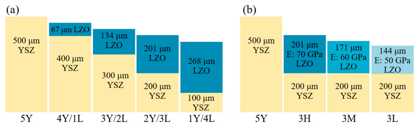
  217. Cheng, B.; Yang, G.-J.; Zhang, Q.; Yang, N.; Zhang, M.; Zhang, Y.; Li, C.-X.; Li, C.-J. Gradient thermal cyclic behaviour of La2Zr2O7/YSZ DCL-TBCs with equivalent thermal insulation performance. J. Eur. Ceram. Soc. 2018, 38, 1888–1896. [Google Scholar] [CrossRef]
  218. Cheng, B.; Wei, Z.-Y.; Chen, L.; Yang, G.-J.; Li, C.-X.; Li, C.-J. Prolong the durability of La2Zr2O7/YSZ TBCs by decreasing the cracking driving force in ceramic coatings. J. Eur. Ceram. Soc. 2018, 38, 5482–5488. [Google Scholar] [CrossRef]
  219. Chen, X.; Zhao, Y.; Fan, X.; Liu, Y.; Zou, B.; Wang, Y.; Ma, H.; Cao, X. Thermal cycling failure of new LaMgAl11O19/YSZ double ceramic top coat thermal barrier coating systems. Surf. Coat. Technol. 2011, 205, 3293–3300. [Google Scholar] [CrossRef]
  220. Gell, M. Application opportunities for nanostructured materials and coatings. Mater. Sci. Eng. A 1995, 204, 246–251. [Google Scholar] [CrossRef]
  221. Siegel, R.W. Nanostructured materials -mind over matter. Nanostruct. Mater. 1994, 4, 121–138. [Google Scholar] [CrossRef]
  222. Padmanabhan, K.A. Mechanical properties of nanostructured materials. Mater. Sci. Eng. A 2001, 304–306, 200–205. [Google Scholar] [CrossRef]
  223. Wu, J.; Guo, H.-B.; Zhou, L.; Wang, L.; Gong, S.-K. Microstructure and thermal properties of plasma sprayed thermal barrier coatings from nanostructured YSZ. J. Therm. Spray Technol. 2010, 19, 1186–1194. [Google Scholar] [CrossRef]
  224. Zhou, C.; Wang, N.; Xu, H. Comparison of thermal cycling behavior of plasma-sprayed nanostructured and traditional thermal barrier coatings. Mater. Sci. Eng. A 2007, 452–453, 569–574. [Google Scholar] [CrossRef]
  225. Zhou, F.; Wang, Y.; Wang, L.; Cui, Z.; Zhang, Z. High temperature oxidation and insulation behavior of plasma-sprayed nanostructured thermal barrier coatings. J. Alloy. Compd. 2017, 704, 614–623. [Google Scholar] [CrossRef]
  226. Chen, D.; Luo, F.; Lou, X.; Qing, Y.; Zhou, W.; Zhu, D. Comparison of thermal insulation capability between conventional and nanostructured plasma sprayed YSZ coating on Ni3Al substrates. Ceram. Int. 2017, 43, 4324–4329. [Google Scholar] [CrossRef]
  227. Lima, R.S.; Marple, B.R. Nanostructured YSZ thermal barrier coatings engineered to counteract sintering effects. Mater. Sci. Eng. A 2008, 485, 182–193. [Google Scholar] [CrossRef]
  228. Lima, R.S.; Marple, B.R. Thermal spray coatings engineered from nanostructured ceramic agglomerated powders for structural, thermal barrier and biomedical applications: A review. J. Therm. Spray Technol. 2007, 16, 40–63. [Google Scholar] [CrossRef]
  229. Lima, R.S.; Kucuk, A.; Berndt, C.C. Bimodal distribution of mechanical properties on plasma sprayed nanostructured partially stabilized zirconia. Mater. Sci. Eng. A 2002, 327, 224–232. [Google Scholar] [CrossRef]
  230. Lima, R.S.; Marple, B.R. Toward highly sintering-resistant nanostructured ZrO2-7wt.%Y2O3 coatings for TBC applications by employing differential sintering. J. Therm. Spray Technol. 2008, 17, 846–852. [Google Scholar] [CrossRef]
  231. Lima, R.S.; Kucuk, A.; Berndt, C.C. Integrity of nanostructured partially stabilized zirconia after plasma spray processing. Mater. Sci. Eng. A 2001, 313, 75–82. [Google Scholar] [CrossRef]
  232. Wang, Z.; Kulkarni, A.; Deshpande, S.; Nakamura, T.; Herman, H. Effects of pores and interfaces on effective properties of plasma sprayed zirconia coatings. Acta Mater. 2003, 51, 5319–5334. [Google Scholar] [CrossRef]
  233. Li, G.; Yang, G. Understanding of degradation-resistant behavior of nanostructured thermal barrier coatings with bimodal structure. J. Mater. Sci. Technol. 2019, 35, 231–238. [Google Scholar] [CrossRef]
  234. Li, G.R.; Wang, L.S.; Zhang, W.W.; Yang, G.J.; Chen, X.F.; Zhang, W.X. Tailoring degradation-resistant thermal barrier coatings based on the orientation of spontaneously formed pores: From retardation to self-improvement. Compos. Part B 2020, 181, 107567. [Google Scholar] [CrossRef]
Figure 1. Typical applications of TBCs in industrial fields.
Coatings 13 00343 g001
Figure 2. Schematic diagram of the preparation process of TBCs: (a) equipment working principle (b) cross-section (c) surface SEM images (adapted from [33,34,35,36,37,38,39,40]).
Coatings 13 00343 g002
Figure 3. Breakdown structure for the brief review.
Coatings 13 00343 g003
Figure 4. Cutaway view of aero-engine GE-9X, thermal barrier coating (TBC) on high-pressure blade, and scanning electron microscope (SEM) image of a cross-section TBC by EB-PVD 7 wt % yttria-stabilized zirconia (7YSZ). (Engine and blade images from GE aviation, and SEM micrographs adapted from Ref. [44]).
Coatings 13 00343 g004
Figure 5. Cutaway view of gas turbine SGT5-4000F, TBC on the first stage blade, and SEM image of TBC cross-section obtained by APS 8 wt % yttria-stabilized zirconia (8YSZ). (Engine from Siemens energy, turbine images from SULZER W501F, and SEM micrographs adapted from Ref. [45]).
Coatings 13 00343 g005
Figure 6. SEM images of the cross-sectional area of different thicknesses for a topcoat of (a) 280 μm (b) 1000 μm [52].
Coatings 13 00343 g006
Figure 7. SEM image and EDS analysis map of the polished cross-section of the TBC with the topcoat of (a) 280 μm (b) 1000 μm after 150 h of oxidation test at 1000 °C [52].
Coatings 13 00343 g007
Figure 8. Effect of topcoat thickness on coating thermal insulation (ΔT is the difference between the surface temperature of the uncoated substrate and the surface temperature of the substrate coated with the TBC), thermal shock lives (at 1000 ℃), and bonding strength. (adapted from [52]).
Coatings 13 00343 g008
Figure 9. Comparison of temperature on the blade surface and the tip surface [55]. (Htc is thickness of the topcoat, LE, LT, and TT are leading edge, leading tip, and trailing tip, respectively).
Coatings 13 00343 g009
Figure 10. Fractured cross-section of as-deposited PS-TBC [61].
Coatings 13 00343 g010
Figure 11. (a) Partially bonded layers of a plasma-sprayed coating prepared by focused ion beam (b) schematic representation of the ‘‘two flux regimes’’ model for heat flow through a set of plates connected via bridges. Analytical model to investigate the dominant effect of 2D pores on the prevention of heat flux: stacking of unit splat segments (c) top view (d) perspective view (e) top view of a basic stacking pattern (f) cross-section of A-A′ corresponding to (e).
Coatings 13 00343 g011
Figure 12. SEM micrographs of cross-sections of TBCs with different parameters: (a) AM1-APS 1: Haynes 188 + 40 μm NiCrAlY + 110 μm YSZ, (b) AM1-APS 2: Haynes 188 + 15 μm NiCrAlY + 430 μm YSZ, (c) DFL-APS:Haynes 188 + 130 μm NiCoCrAlY + 330 μm YSZ, (d) In-APS: Inconel 600 + 72 μm NiCrAlY + 230 μm YSZ, (e) AM1-APSmf: Haynes 188 + 15 μm NiCrAlY + 90 μm YSZ, and (fj) are the corresponding higher magnifications of the ceramic coatings [92].
Coatings 13 00343 g012
Figure 13. (a) Porosity and (b) thermal diffusivity of TBCs, (INJ-APS: Haynes 188 + 70 μm NiCoCrAlY + 450 μm YSZ, CC-APS: Haynes 188 + 135 μm NiCoCrAlY + 190 μm YSZ, other group parameters are consistent with Figure 9 [92].
Coatings 13 00343 g013
Figure 14. The evolution of thermal conductivity (a) with pore sizes at different total porosities (b) with pore angles at different pore aspect ratios [73].
Coatings 13 00343 g014
Figure 15. Normalized thermal diffusivity of TBCs as a function of isothermal heat treatment time at 1100 °C (a) freestanding coatings (b) full TBCs [92].
Coatings 13 00343 g015
Figure 16. Normalized thermal diffusivity of TBCs at different temperatures as a function of thermal exposure time [96].
Coatings 13 00343 g016
Figure 17. In situ healing of 2D pores of APS-TBC during thermal exposure: (a) a pore of less than 50 nm width (b) a pore of approximately 200 nm width [61].
Coatings 13 00343 g017
Figure 18. (a) Aspect ratio distribution of interlamellar 2D pores in APS-TBC exposed at 1300 °C for different durations (b) relationship between the pore normalized area, normalized thermal conductivity, and aspect ratio (adapted from [103,109]).
Coatings 13 00343 g018
Figure 19. SEM cross-sections of as-sprayed, free-standing TBCs with different porosity gradients: (a) positive gradient (Model-P) with increasing porosity from top to bottom (b) negative gradient (Model-N) with decreasing porosity (c) homogeneous porosity (Model-H) with uniform porosity distribution; porosity distributions of top, middle and bottom sublayers at different sintering time in (d) Model-P (e) Model-N (f) Model-H [140].
Coatings 13 00343 g019
Figure 20. Evolution of stress state at the bottom of graded and homogenous porous coatings in the graded temperature field [140].
Coatings 13 00343 g020
Figure 21. Schematic illustration of how the layers are arranged in the FGTTBC-PG and the parameters used to create these layers [147].
Coatings 13 00343 g021
Figure 22. SEM images of the sample cross-section: (a) TTBC (b) FGTTBC (c) FGTTBC-P (d) FGTTBC-PG [147].
Coatings 13 00343 g022
Figure 23. (a) Bonding strength (b) the fracture toughness (c) the thermal shock lives (d) substrate temperature diagrams of all coated samples [147].
Coatings 13 00343 g023
Figure 24. Photographs of (a) TBC under thermal gradient test at 1200 °C (b) FG-TBC not failed at 265 cycles (c) traditional 8YSZ cracked at 156 cycles [150].
Coatings 13 00343 g024
Figure 25. SEM micrographs of cross-section of as-sprayed YSZ-TTBCs, the segmentation crack densities of (ac) are 2.7 mm−1 crack density, 1.5 mm−1 crack density and 0.9 mm−1 crack density [118].
Coatings 13 00343 g025
Figure 26. Photographs of TBCs showing coating failure modes: (ac) 2.7 mm−1 crack density coating cycled to 1238 °C for 1200 cycles and 1770 cycles, and to 1335 °C for 320 cycles, respectively; (df) 2.7 mm−1 crack density coating cycled to 1226 °C for 1650 cycles and 1810 cycles, and to 1317 °C for 174 cycles, respectively; (g,h) 0.9 mm−1 crack density coating cycled to 1216 °C for 1071 cycles and to 1327 °C for 217 cycles, respectively [118].
Coatings 13 00343 g026
Figure 27. Burner rig test results for TTBCs with segmentation crack densities of (a) 4/mm and (b) 2.1/mm [158].
Coatings 13 00343 g027
Figure 28. Radial stress distribution of TTBCs with different segmentation crack densities [158]. (a) 0.79 mm−1 crack density; (b) 1.59 mm−1 crack density; (c) 2.38 mm−1 crack density; (d) 3.17 mm−1 crack density; (e) 3.97 mm−1 crack density; (f) 4.76 mm−1 crack density; (g) 5.56 mm−1 crack density; (h) 6.35 mm−1 crack density, () shows the scalar of the contour of the corresponding figures (ad) (unit: MPa).
Coatings 13 00343 g028
Figure 29. (a) The plot of stress intensity factor (the intersection point at the right side of each plotted curve can be defined as the upper crack density for the specific TTBCs with improved thermal shock resistance) and (b) the energy release rate of the segmentation crack as the function of the segmentation crack density [158].
Coatings 13 00343 g029
Figure 30. Effect of condensation behavior on the coating structure [164,165].
Coatings 13 00343 g030
Figure 31. The SEM micrograph of the PS-PVD coatings, (a) fractured cross-section of the YSZ coating (b) polished cross-section of the YSZ coating (c,d) voids and interfaces between small columns of the YSZ coating (e) fractured cross-section of the GZO coating (f) polished cross-section of the GZO coating (g,h) voids and interfaces between small columns of the GZO coating [173].
Coatings 13 00343 g031
Figure 32. The YSZ coating model: (a) heat flux field (b) cross-section of heat flux field, the GZO coating model (c) heat flux field (d) cross-section of heat flux field [173].
Coatings 13 00343 g032
Figure 33. Cross-sectional microstructures of as-sprayed TTBCs: (a) SPS (b) APS coating [181].
Coatings 13 00343 g033
Figure 34. Number of sustained cycles at 1100 ℃ for SPS coating and APS coating [181].
Coatings 13 00343 g034
Figure 35. (a) Crystal structure (b) calculated and experimental temperature-dependent thermal conductivities of the rare-earth zirconate [189,205,206].
Coatings 13 00343 g035
Figure 36. Characteristics of crystal structures in m’ phase RETaO4 (RE = Yb, Lu, Sc) ceramics: (a) YbTaO4 (b) ScTaO4 [193].
Coatings 13 00343 g036
Figure 37. SEM photographs of RETaO4 (RE = Nd, Eu, Gd, Dy, Er, Yb, Lu) ceramics [194].
Coatings 13 00343 g037
Figure 38. (a) Crystal structure (b) thermal conductivity of RENbO4 ceramic [196].
Coatings 13 00343 g038
Figure 39. The microstructure of RENbO4 ceramics sintered at 1600 °C for 10 h: (a) NdNbO4 (b) SmNbO4 (c) GdNbO4 (d) DyNbO4 (e) ErNbO4 (f) YbNbO4 [196].
Coatings 13 00343 g039
Figure 40. Thermal conductivity versus thermal expansion coefficient [216].
Coatings 13 00343 g040
Figure 41. Schematic diagram of DCL structure: (a) equivalent thermal insulation with different thickness ratio (b) equivalent thermal insulation with different modulus [217,218].
Coatings 13 00343 g041
Figure 42. Cross-sectional SEM images of DCL TBCs: (a) equivalent thermal insulation with different thickness ratio (be) equivalent thermal insulation with different modulus [217,218].
Coatings 13 00343 g042
Figure 43. Lifetime of DCL TBCs under gradient thermal cyclic tests at 1300 °C TC surface and 940 °C backside surface: (a) equivalent thermal insulation with different thickness ratio (b) equivalent thermal insulation with different modulus [217,218].
Coatings 13 00343 g043
Figure 44. Global structural evolution during thermal exposure: (A) conventional TBCs (B) nanostructured TBCs [233].
Coatings 13 00343 g044
Figure 45. Changes in (a) elastic modulus (b) thermal conductivity as a function of thermal exposure duration [233].
Coatings 13 00343 g045
Figure 46. Schematic diagram of the three kinds of TBCs: (i) mono-layered TBCs without nano-inclusions (mono-TBCs); (ii) composited TBCs with isotropic nano-inclusions (composite-TBCs-1); (iii) composited TBCs with anisotropic nano-inclusions (composite-TBCs-2) [234].
Coatings 13 00343 g046
Figure 47. Structural evolution of the three kinds of TBCs during thermal exposure [234].
Coatings 13 00343 g047
Figure 48. Changes in (a) 2D pore density (b) normalized thermal conductivity during thermal exposure [234].
Coatings 13 00343 g048
Table 1. Thermal physical properties of potential TC materials.
MaterialThermal Conductivity
/(W·m−1·K−1)
Thermal Expansion Coefficient/(10−6 K−1)Elastic
Modulus/
(GPa)
Fracture
Toughness/
(MPa m 1/2)
YSZ [4,187]2.20 (1000 °C)10.70 (1000 °C)210 ± 103 ± 0.5
Rare-earth zirconates
La2Zr2O7 [68,182,189]1.56 (1000 °C)9.10 (1000 °C)1862.1 ± 0.1
Gd2Zr2O7 [188,189,190]1.60 (700 °C)11.60 (1000 °C)2052.2 ± 0.2
Dy2Zr2O7 [191]1.34 (800 °C)10.80 (1000 °C)
Yb2Zr2O7 [192]1.36 (800 °C)11.90 (1000 °C) 2.2 ± 0.1
Rare-earth tantalates
YTaO4 [193]1.5 1405
NdTaO4 [194]1.41 (800 °C) 178
GdTaO4 [195]1.70 (800 °C) 154
YbTaO4 [193]1.65–37.6 (1200 °C)122
EuTaO4 [195]1.26 (900 °C) 175
Rare-earth niobates
NdNbO4 [196]2.0 (1000 °C)11.80 (1000 °C)108
SmNbO4 [196]2.05 (1000 °C)10.86 (1000 °C)120
GdNbO4 [196]1.66 (1000 °C)10.30 (1000 °C)131
Other oxides
CaZrO3 [197]0.73 (600 °C)9.00 (1000 °C)
SrZrO3 [198]2.08 (1000 °C)10.90 (1000 °C)170 ± 41.5 ± 0.1
BaZrO3 [199]3.42 (1000 °C)7.90 (1000 °C)181 ± 11
YAlO3 [200]1.61 (min) 318
YbAlO3 [201]1.15 (min)9.62257
LaPO4 [202]1.30 (1000 °C)10.50 (1000 °C)1311.1 ± 0.2
CePO4 [202]1.359.9 1.8 ± 0.1
NdPO4 [202]1.599.8 2 ± 0.2
LaMgAl11O19 [203]1.95 (1000 °C)10.95 (20~1000 °C)130 ± 114.6 ± 0.5
LaTi2Al9O19 [204]1.30 (1000 °C)11.2 (1000 °C)240 ± 131.9–2.5
Disclaimer/Publisher’s Note: The statements, opinions and data contained in all publications are solely those of the individual author(s) and contributor(s) and not of MDPI and/or the editor(s). MDPI and/or the editor(s) disclaim responsibility for any injury to people or property resulting from any ideas, methods, instructions or products referred to in the content.

