Article

Mechanical Properties Evolution and Damage Mechanism of Kevlar Fiber under Ozone Exposure in Near-Space Simulation

1
School of Materials Science and Engineering, Hebei University of Technology, Tianjin 300401, China
2
School of Mechanical Engineering, Hebei University of Technology, Tianjin 300130, China
3
State Key Laboratory of Reliability and Intelligence Electrical Equipment, Hebei University of Technology, Tianjin 300401, China
4
Department of Vehicle and Electrical Engineering, Army Engineering University of PLA, Shijiazhuang 050003, China
*
Authors to whom correspondence should be addressed.
Coatings 2022, 12(5), 584; https://doi.org/10.3390/coatings12050584
Submission received: 28 March 2022 / Revised: 18 April 2022 / Accepted: 22 April 2022 / Published: 24 April 2022
(This article belongs to the Special Issue Novel Coatings for Corrosion Protection)

Abstract

:
The stratospheric airship, a long-term floating vehicle in near-space, has become a new hotspot in aerospace exploration. The airship’s envelope material is vulnerable to ozone exposure in near-space and degrades. This paper used typical Kevlar fiber as the research material for an ozone exposure experiment in a near-space simulated environment. The results showed that the elongation of the Kevlar fiber decreased and the elastic modulus increased after ozone exposure. The tensile strength of fiber decreased gradually with an increase in ozone concentration and exposure time. When ozone concentration increased from 0 pphm to 1000 pphm, the tensile strength of fiber decreased from 2397 MPa to 2059 MPa. With increasing ozone exposure time from 0 h to 1000 h under ozone concentration 1000 pphm, the tensile strength of fiber decreased from 2332 MPa to 1954 MPa. The hydrogen bonds and partial amide groups in the fiber structure were damaged, and the surface chemical functional groups of the Kevlar fiber were reassembled under ozone exposure. Low molecular weight oxidation products, including -COO- structures, formed on the surface of the Kevlar fiber. This work explores the ground simulation method in a near-space environment and enriches the service data of airship envelope materials.

1. Introduction

Near-space, 20–100 km above sea level, is the space where aviation and aerospace converge and has gradually become more utilized and developed in the fields such as science, technology, and military applications [1,2,3]. Near space vehicle has many advantages, such as a highly effective cost ratio, good maneuverability, and low technical difficulty of payload updating and maintenance for both high dynamic and low dynamic aircraft. At present, various approaches for developing near-space vehicles have been proposed. A stratospheric airship is an important fixed-point platform that, with geosynchronous satellites, can be used as an effective supplement for satellites and aircraft. It has great advantages in military reconnaissance, space early warning, communication relay, and space exploration [4].
The efficiency of the airship, such as buoyancy height, duration of flight, payload, service life, etc., is directly affected by the mechanical properties of the envelope materials that are the main structural materials of the airship [5,6,7]. A high-performance envelope involves a variety of special functional materials such as high specific strength fabric, high barrier materials, adhesives, anti-aging agents, etc. In recent years, with the advance in fiber manufacturing technology, Kevlar and other fibers with excellent mechanical properties and good heat resistance have emerged [8,9,10,11,12,13].
Kevlar fiber has excellent properties such as high strength, high modulus, and high temperature resistance. Due to these characteristics, it can be used as the main structural reinforcement layer of airship envelope materials to enhance the mechanical strength of envelope materials [14]. In addition to its applications in the aerospace field, Kevlar fiber is also widely used in tires, bulletproof devices, sports equipment, high-strength rope, and other products [15,16]. With the appearance of Kevlar fiber and other new airship envelope materials, the environmental effect and service reliability of envelope materials have become one of the key scientific and technological issues in the long-term service of airships in the face of a complex and changeable near-space environment. Near-space spans multiple atmospheric layers, including the ozone and ionosphere, and encounters solar ultraviolet radiation, high temperature, particle radiation, aero-thermal and re-entry plasma, meteoroids, and other environments [17]. Envelope materials are vulnerable to ozone in the near-space atmosphere and deteriorate in quality, as shown in Figure 1 [18]. The ozone content can vary from 0.4 mg/m3 at the maximum to 0.2 mg/m3 at the minimum level. Therefore, the environmental effect of ozone on the airship envelope material in near-space should not be ignored [19,20].
Similar to the space environment, the environmental conditions in near-space are especially extreme, with environmental conditions that do not exist on the ground. In order to systematically study the environmental adaptability of vehicle materials in near-space, ground simulation studies need to be carried out. The traditional natural environment test method has a long test cycle, which is not well equipped to meet the needs of equipment development, testing, and evaluation. Although the laboratory simulated environment test method has the advantage of a short test cycle, it cannot reflect the failure law in the real environment [21,22,23].
The accelerated test method for the ground simulated environment accelerates the deterioration of equipment or material properties by appropriately strengthening some environmental factors under natural environmental conditions. It combines the advantages of the natural environment test and laboratory simulation environment test and has the favorable characteristics of reality, reliability, and short test period [24,25]. Thus, establishing a reasonable ground acceleration test method is an important foundation for evaluating the environmental adaptability of near-space vehicles in the exploration stage.
This study used typical high-performance Kevlar fabrics as envelope research materials for ground-level ozone accelerated test research. The change law of mechanical properties of Kevlar fiber was characterized, and the change mechanism of surface micromorphology and molecular structure was analyzed in an ozone environment. This work will enrich the data of airship envelope materials in a near-space environment and provide a useful reference for ground simulation and life prediction technology in a near-space environment.

2. Materials and Methods
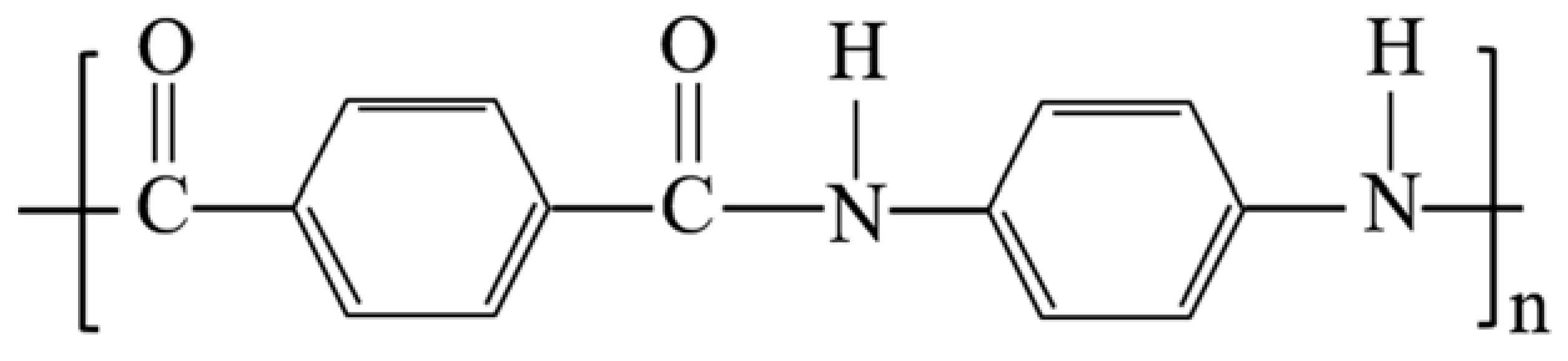
2.1. Materials

The experimental material used in this paper was orange Kevlar fiber (Para-aramid fiber, DuPont, DE, USA). The molecular structure formula of the Kevlar fiber is shown in Figure 2. The fiber contains a benzene ring structure and amide group. The conjugation effect of the benzene ring and amide group leads to greater rigidity of the molecular chain, so Kevlar fiber has excellent mechanical properties [26,27]. Each Kevlar cord used in this paper was braided using three fiber bundles composed of many small fiber monofilaments, as shown in Figure 3.
Kevlar monofilament with a diameter of about 12 μm was used as the research object in this experiment. The fiber monofilament selected randomly was fixed on cowhide coordinate paper with acrylic adhesive (TA-868) and paralleled to the long edge of the paper frame. Then, 2 pieces of kraft paper with a length and width of 35 mm were glued to both ends of the cowhide coordinate paper. The preparation process of fiber monofilament and the sample after molding are illustrated in Figure 4.

2.2. Testing and Characterization

The mechanical properties of Kevlar fiber monofilament were tested with a universal tensile testing machine (INSTRON 3365, Boston, MA, USA). According to ASTM C 1557-2003 [28], the upper and lower ends of the paper frame were fixed between the two fixtures of the tensile testing machine before the experiment, and the fiber was straightened with 0.4 N force to ensure that the fiber was straight before the test. Then, the fiber was loaded at a speed of 0.01 mm/s, and the tensile test was carried out until the fiber broke. The ultimate load was obtained as the tensile strength of a single filament [29].
The surface morphology of the Kevlar fiber monofilament was observed by ultra-high-resolution thermal field emission scanning electron microscope (JSM-7610F, JEOL, Tokyo, Japan), and its acceleration voltage was 3 kV. Before observation, the sample surface was sprayed with gold (palladium gold alloy with a particle size of about 20 nm was selected). The surface attenuated total reflection FT-IR spectroscopic of the fiber monofilament was characterized by Fourier transform infrared spectrometer (VERTEX80V, Bruker, Billerica, MA, USA). The element types, chemical bonds, and relative contents on the sample surface were identified by X-ray photoelectron spectroscopy (Escalab 250Xi, Thermo Fisher Scientific Inc., Waltham, MA, USA). The excitation source adopted a monochromatic Al target, and the best spatial resolution was 1 μm. The signal was accumulated for 5–10 cycles, and the charge correction was carried out with C 1s at 285.0 eV binding energy as the energy standard.

2.3. Ozone Exposure

The ozone exposure test was carried out using an ozone aging test chamber (GH-150, Future Science and Technology Application Research, Tianjin, China), which can adjust the ozone concentration range from 10 to 1000 pphm. In this test, Kevlar fiber monofilament samples were placed into the ozone aging test chamber for the ozone exposure test at room temperature (25 °C), and the correlation between fiber strength, ozone concentration, and exposure times was investigated. Within 100 h, ozone concentrations were 0, 100, 300, 500, 800, 1000 pphm (equivalent to 0, 2.14, 6.43, 10.71, 17.14, 21.43 mg/m3 after unit conversion). At 1000 pphm ozone concentration, the exposure time was 0, 100, 300, 500, and 1000 h, respectively. To increase the validity of the test results, 3 samples were selected as a group for each test condition. A set of 3 samples was averaged to determine the final test results.

3. Results and Discussion

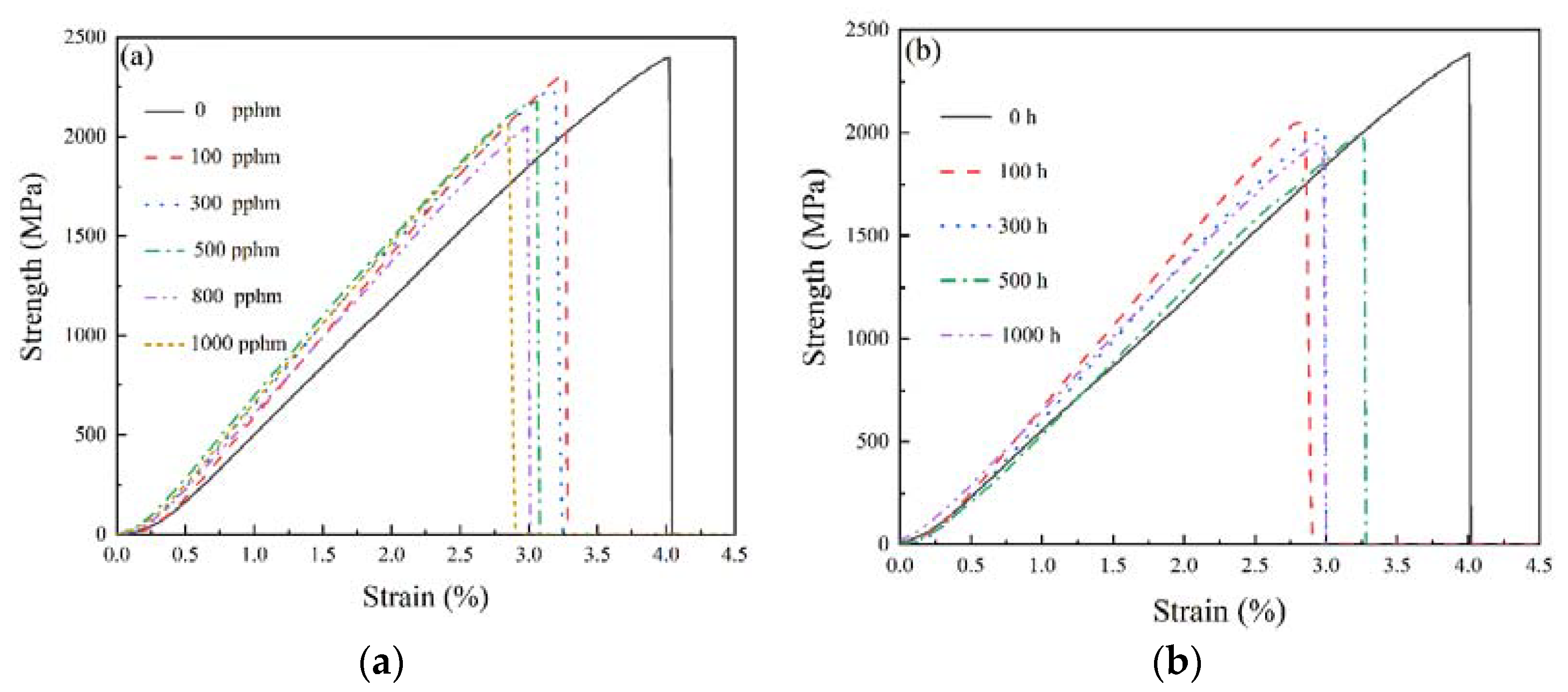
3.1. Mechanical Properties Characterization

For ozone concentrations of 0, 100, 300, 500, 800, and 1000 pphm, the Kevlar fiber’s stress–strain relationship before and after 100 h exposure tests are shown in Figure 5a. The stress and strain of Kevlar fiber showed a linear relationship, relating to the fact that the molecular structure of Kevlar fiber is composed of rigid molecular chains [30]. After ozone exposure, the elongation of Kevlar fiber decreased, and the elastic modulus increased. The tensile strength of fiber decreased gradually with the increase in ozone concentration. When ozone concentration was 0 pphm, the tensile strength of the fiber was 2397 MPa. However, the tensile strength of the fiber reduced to 2059 MPa, when ozone concentration was 1000 pphm.
For ozone exposure times of 0, 100, 300, 500, and 1000 h, the Kevlar fiber’s stress–strain relationship before and after 1000 pphm ozone exposure tests are shown in Figure 5b. By comparing Figure 5a,b, it can be seen that the relationship between mechanical properties and ozone exposure time at a certain concentration was similar to the relationship between mechanical properties and ozone concentration at a certain time. Namely, after the ozone exposure test at a concentration of 1000 pphm for a different time, the elongation of the Kevlar fiber also decreased. The elastic modulus increased, and the tensile strength of fiber decreased gradually with the increase of ozone exposure time. With increasing ozone exposure time from 0 h to 1000 h under ozone concentration 1000 pphm, the tensile strength of fiber decreased from 2332 MPa to 1954 MPa.
The strength of the Kevlar fiber is one of the important indexes of airship envelope material. Figure 6 examines the correlation between the tensile strength of the fiber and ozone concentration and exposure time. It can be seen from the figure that with the increase in ozone concentration (Figure 6a), or the exposure time in the ozone environment (Figure 6b), the strength of the Kevlar fiber had a trend of rapid decrease at first and then gradually gentle. The curves of the relationship between the tensile strength of the fiber, ozone concentration, and exposure time could be fitted as follows:
σ t 100 = 1973 + 464 [ 1 + ( C 303 ) 0.74 ]
σ c 1000 = 1895 + 455 [ 1 + ( T 91 ) 0.75 ]
where σt100 is the strength (MPa) of Kevlar fiber when the ozone exposure time is 100 h; σ c1000 is the strength (MPa) of Kevlar fiber when ozone concentration is 1000 pphm; C denotes ozone concentration (pphm), and T represents ozone exposure time (h).
From Formulas (1) and (2), the strength of Kevlar fiber corresponding to ozone concentration (under the condition of exposure time of 100 h) and ozone exposure time (under the condition of ozone concentration of 1000 pphm) in a certain range could be obtained.
SPSS statistical software (version 26.0) was used to analyze the correlation between ozone concentration, ozone exposure test time, and the tensile strength of Kevlar fibers. The results showed a highly negative correlation between ozone concentration and tensile strength (γ = −0.986), and there was a significant negative correlation between the time of ozone exposure test and tensile strength (γ = −0.688). This showed that the test data were within a reasonable error range.

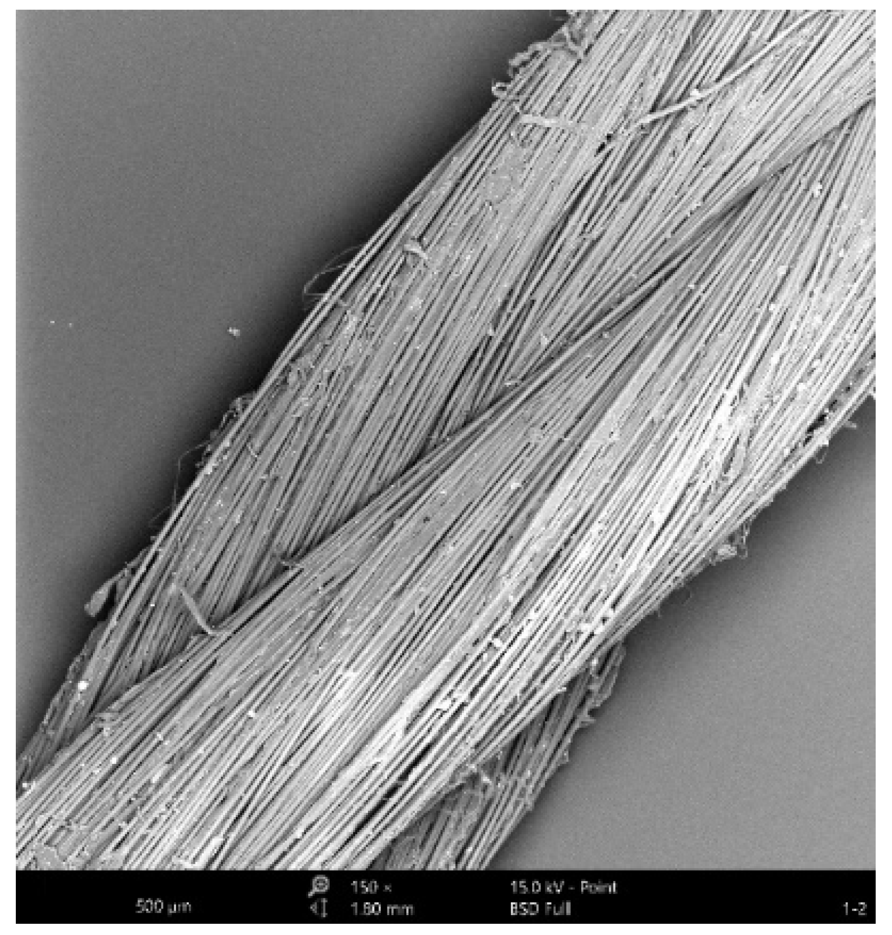
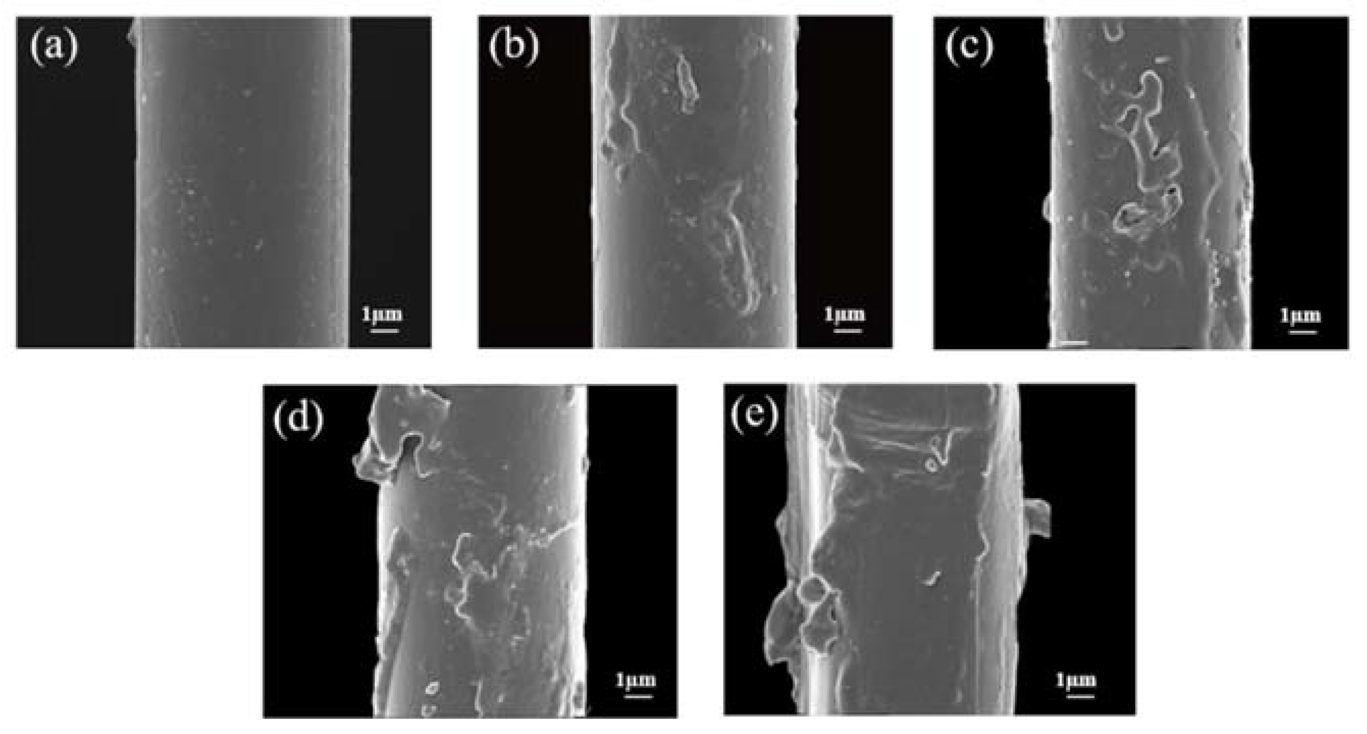
3.2. Morphology Analysis

Macroscopic pictures of the Kevlar fiber surface before and after ozone exposure are shown in Figure 7. Before the ozone exposure tests, the sample surface looked smooth (as shown in Figure 7a). This is mainly because the surface layer of the fiber is composed of rigid molecules with high crystallinity for lots of intermolecular hydrogen bonds [31]. After ozone exposure, the surface morphology of the Kevlar fiber gradually coarsened and even peeled off with the increase in ozone exposure time. After 100 h of ozone exposure, the surface of the fiber formed depression and bulge morphology (as displayed in Figure 7b). As the ozone exposure time was further extended, the degree of surface roughness increased (as shown in Figure 7c,d). When ozone exposure time reached 1000 h, the fiber surface appeared wrinkled and even peeling, as shown in Figure 7e. The variation of fiber surface might be related to the local movement of molecular chains and the reduction in free volume [32].

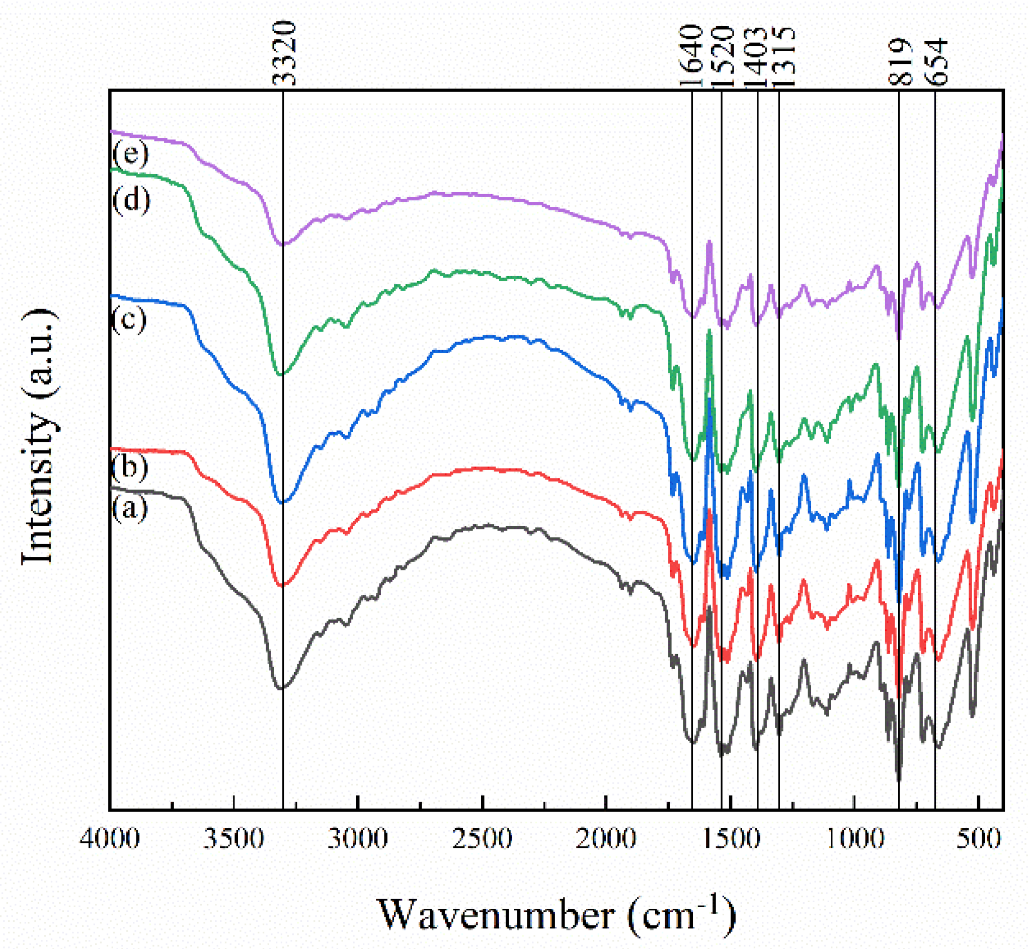
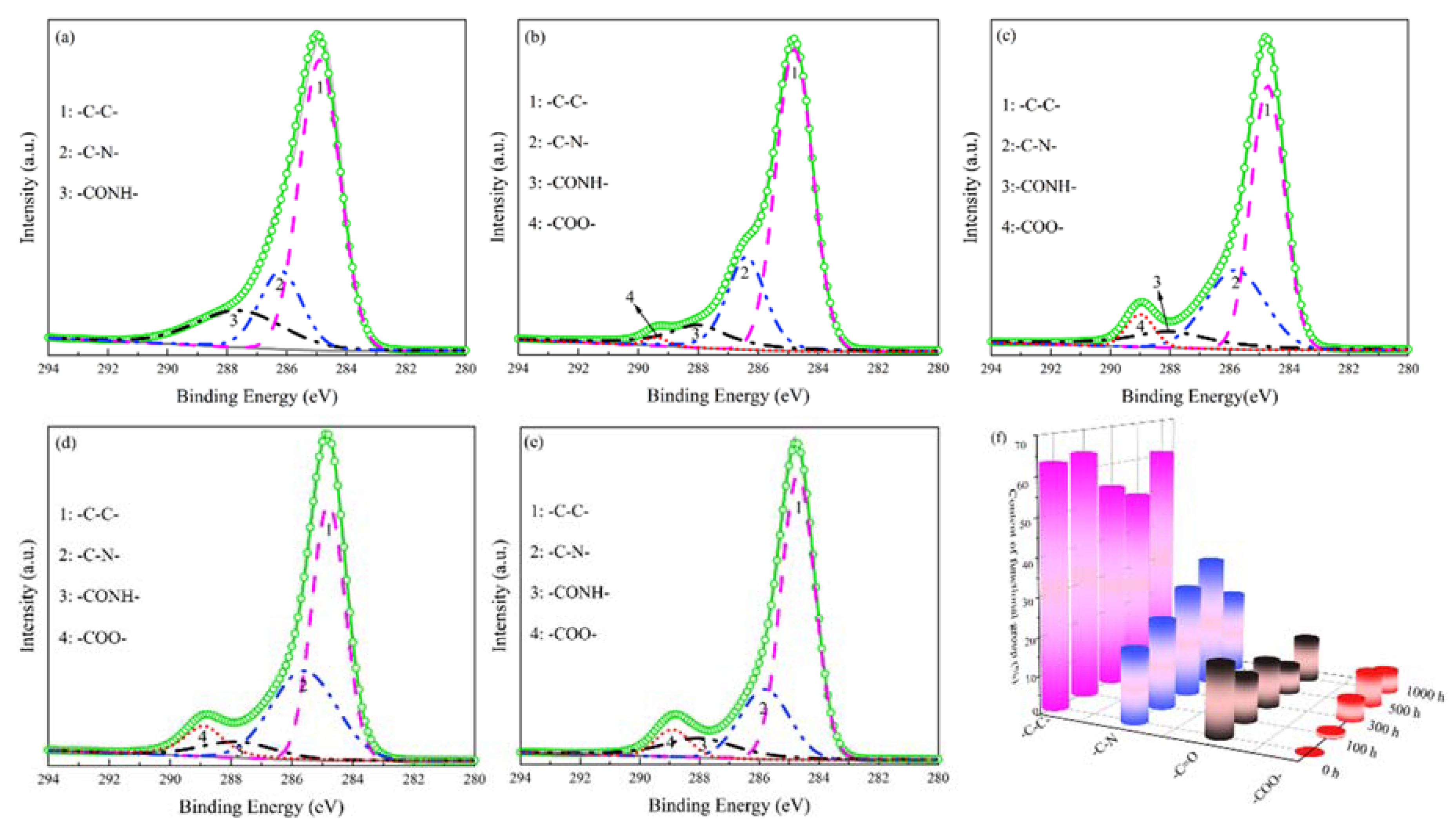
3.3. Surface Structure Characterization

Figure 8 is the FT-IR spectroscopic of the Kevlar fiber before and after ozone exposure and shows the positions of the absorption peaks of the main functional groups. The FT-IR spectroscopic of the original Kevlar fiber is shown in Figure 8a. The wide peak near 3320 cm−1 is the stretching vibration absorption peak of the hydrogen bond formed by the association of the N-H bond and C=O bond in the aramid structure. The vibration absorption peak (amide I band) near 1640 cm−1 is the stretching vibration characteristic absorption peak of the aramid amide bond (C=O). The absorption peaks near 1520 cm−1 (amide II band) and 1403 cm−1 (amide III band) correspond to the cooperative vibration peak of the C-N and N-H bond [33]. The absorption peak near 1315 cm−1 (amide III band) expresses the characteristic absorption peak of ph-N (“ph” stands for phenyl group; phenyl is the group left after removing a hydrogen atom from any carbon in benzene molecule.). The absorption peaks near 819 cm−1 and 654 cm−1 indicate the presence of a benzene ring structure [34,35].
When Kevlar fibers were exposed to ozone tests, as summarized in Figure 8b–e, the absorption peaks mentioned above still existed, but the relative intensity of each vibration absorption peak gradually weakened with ozone exposure time. The intensity ratio of each absorption peak is given in Table 1. The relative intensity ratio of hydrogen bond absorption peak near 3320 cm−1 decreased after ozone exposure, while the intensity ratio of amide group absorption peaks near 1315 cm−1, 1403 cm−1, and 1520 cm−1 increased after 100 h of ozone exposure. It indicates that after ozone exposure, the hydrogen bond formed by the amide group between the lateral molecular chains was damaged, and the macromolecular main chain binding would further be enhanced. Therefore, the elastic modulus of the fiber increased when the fiber was stretched. This was also consistent with the above test results of the mechanical properties of Kevlar fiber.
X-ray photoelectron spectroscopy (XPS) was used to analyze the changes of surface elements and chemical bonds of samples to understand further the damage mechanism of samples exposed to ozone. Figure 9 is XPS full scan spectra of Kevlar fibers before and after ozone exposure. The peaks of photoelectron energy spectra at about 285, 400, and 532 eV are attributed to C, N, and O atoms, respectively [36]. C, N, and O are the main chemical components of the Kevlar fiber surface; their relative chemical composition is shown in Table 2. After exposure to ozone tests, the relative content of oxygen element on the Kevlar fiber surface showed an overall trend of increase. The O/C ratio was about 0.18 before and after 100 and 300 h of ozone exposure and increased to 0.21 after 500 and 1000 h of ozone exposure. This phenomenon can be attributed to the strong oxidation capacity of ozone, which introduced a large number of oxygen atoms to the surface of the Kevlar fiber, resulting in partial oxidation of the molecular chain on the surface of the fiber.
The high-resolution spectra of C1s and the peak fitting curves by XPSEAK software (version 4.1) before and after exposure to ozone for 100, 300, 500, and 1000 h are summarized in Figure 10. As can be seen from Figure 10a, the C1s high-resolution spectrum of the original Kevlar fiber can be decomposed into 3 fitting peaks with binding energy near 285, 286, and 288 eV, corresponding to the chemical states of C atoms in -C-C-, -C-N-, and -C=O functional groups respectively. After ozone exposure, the C1s high-resolution spectrum can be fitted to 4 separate peaks, as shown in Figure 10b–e. The fitted peak added with binding energy near 289 eV was attributed to the -COO- functional group [36,37]. It can be seen from Table 3 and Figure 10f that the content of the -COO- functional group on the Kevlar fiber surface was correlated with ozone exposure time. With increasing ozone exposure time, the percentage of -COO- functional group first increased and reached the maximum value of 8.82% after 500 h of ozone exposure. However, when the ozone exposure time was further extended to 1000 h, the percentage of the -COO- functional group decreased. This phenomenon was attributed to the partial peeling of the surface layer on the Kevlar fiber, and a partial sub-surface was exposed as a new surface (as shown in Figure 7).
According to the test and analysis results above, partial chemical functional groups on the surface of the Kevlar fiber recombined, induced by ozone molecules. The interaction between the Kevlar fiber and ozone molecules can be roughly divided into two stages, including hydrogen bond destruction and amide bond damage. The reaction mechanism is shown in Figure 11.
There is a hydrogen bond between the H atom and O atom in the molecular chain of the Kevlar fiber. Ozone is composed of an oxygen molecule and an oxygen atom. The 4 electrons are shared by 3 oxygen atoms, so the central oxygen appears with a partial positive charge, and the terminal oxygen has a partial negative charge. At the initial stage of ozone exposure (100 h), the hydrogen bond is destroyed. Due to the lone pair of electrons provided by the O atom in the amide group, the ozone molecule forms a coordination bond with it. Meanwhile, -NH is released from the binding of the hydrogen bond, which is manifested in an increase in the content of the C-N group, and the electron density of the amide group increases. Finally, the crystal regularity of the molecular chain of aramid fiber is destroyed [38]. This is consistent with the results of the infrared analysis.
The amide bonds (-CONH-) in the Kevlar fiber molecule possessed a certain electronegativity, which was vulnerable to attack and damage from the positively charged oxygen atom in the ozone molecule. With the extension of ozone exposure time, part of the amide bonds was broken, and end groups were oxidized to form a -COO- structure, such as small molecular weight products containing carboxylic acid groups -COOH [35,39].

4. Conclusions

The mechanical properties and damage mechanism of Kevlar fiber were investigated by ground simulation of a near-space ozone environment in this paper. After ozone exposure tests, the elongation of the Kevlar fiber decreased, and the elastic modulus increased. The tensile strength of fiber decreased gradually with an increase in ozone concentration and exposure time. When ozone concentration increased from 0 pphm to 1000 pphm, the tensile strength of fiber decreased from 2397 MPa to 2059 MPa. With increasing ozone exposure time from 0 h to 1000 h under ozone concentration 1000 pphm, the tensile strength of fiber decreased from 2332 MPa to 1954 MPa.
With the increase in ozone exposure time, the surface morphology of the Kevlar fiber gradually roughened and even peeled off. The hydrogen bonds and amide groups connected by rigid molecular chains in the fiber structure were damaged and aged.
After ozone exposure, the relative contents of oxygen and O/C ratio on the surface of the Kevlar fiber increased. At the initial stage of ozone exposure (100 h), hydrogen bonds were broken. Due to the lone pair electrons provided by O atoms in the amide group, ozone molecules formed coordination bonds with it, and the hydrogen bonds formed by the amide groups in the lateral molecular chains were broken. The chemical functional groups on the surface of the Kevlar fiber were reorganized under long-term ozone conditions. The positively charged oxygen atoms in the ozone molecule further destroyed the electronegative amide bonds, forming the -COO- structure, such as low molecular weight oxidation products containing carboxylic acid groups. Therefore, this study on the damage behavior of Kevlar fiber exposed to ozone has reference value for designing and developing promising airship envelope materials with good weather resistance.

Author Contributions

Conceptualization, Q.W., methodology, Q.W. and H.F.; investigation, J.M. and Z.Q., writing—original draft preparation, J.M., writing—review and editing, J.M. and Q.W., supervision, Q.W. and Z.Q., project administration, Q.W. and N.H., funding acquisition, Q.W. and N.H. All authors have read and agreed to the published version of the manuscript.

Funding

This work was supported by the Natural Science Foundation of Hebei Province (Grant No.: E2019202106), the National Natural Science Foundation of China (Grant No.: 51873146 and 81873316), and the Fund for Innovative Research Groups of the Natural Science Foundation of Hebei Province (Grant No. A2020202002).

Institutional Review Board Statement

Not applicable.

Informed Consent Statement

Not applicable.

Data Availability Statement

Data is contained within the article.

Conflicts of Interest

The authors declare no conflict of interest.

References

  1. Liu, Y.Y.; Liu, Y.X.; Liu, S.Z.; Tan, H.F. Effect of Accelerated Xenon Lamp Aging on the Mechanical Properties and Structure of Thermoplastic Polyurethane for Stratospheric Airship Envelope. J. Wuhan Univ. Technol.-Mater. Sci. Ed. 2014, 29, 1270–1276. [Google Scholar] [CrossRef]
  2. Chen, F.G.; Chen, G.G.; Liu, K.H. Analysis of Near Space Environment and Its Effect. Equip. Environ. Eng. 2013, 10, 71–75. [Google Scholar] [CrossRef]
  3. Jamison, L.; Sommer, G.S.; Porche, I.R., III. High-Altitude Airships for the Future of The Force Army. Rand Corp. 2006, 75, 151–155. [Google Scholar]
  4. Kang, W.; Suh, Y.; Woo, K.; Lee, I. Mechanical property characterization of film-fabric laminate for stratospheric airship envelope. Compos. Struct. 2006, 75, 151–155. [Google Scholar] [CrossRef]
  5. Fei, C.; Wang, Z.Q.; Zhou, X.Y.; Wang, F. Research Status of Near Space Airship Envelop Materials. Fiber Compos. 2016, 33, 24–26. [Google Scholar]
  6. Said, M.A.; Dingwall, B.; Gupta, A.; Seyam, A.M.; Mock, G.; Theyson, T. Investigation of ultra violet (UV) resistance for high strength fibers. Adv. Space Res. 2006, 37, 2052–2058. [Google Scholar] [CrossRef] [Green Version]
  7. Qiu, Z.; Chen, W.; Gao, C. Initial configuration and nonlinear mechanical analysis of stratospheric nonrigid airship envelope. J. Aerosp. Eng. 2019, 32, 04018155. [Google Scholar] [CrossRef]
  8. Chen, L. Study on Comprehensive Performance of Several High-Performance Fibers. Ph.D. Thesis, Beijing University of Chemical Technology, Beijing, China, 2016. [Google Scholar]
  9. Dobb, M.G.; Johnson, D.J.; Saville, B.P. Supramolecular Structure of a High-modulus polyaromatic fiber (Kevlar 49). J. Polym. Sci. Polym. Phys. Ed. 2010, 15, 2201–2211. [Google Scholar] [CrossRef]
  10. Maekawa, S.; Nakadate, M.; Takegaki, A. On the Structures of the Low Altitude Stationary Flight Test Vehicle. J. Aircr. 2013, 44, 662–666. [Google Scholar] [CrossRef]
  11. Liu, T.M.; Zheng, Y.S.; Hu, J. Surface modification of aramid fibers with novel chemical approach. Polym. Bull. 2011, 66, 259–275. [Google Scholar] [CrossRef]
  12. Xi, M.; Li, Y.L.; Shang, S.Y.; Li, D.H.; Dai, X.Y. Surface modification of aramid fiber by air DBD plasma at atmospheric pressure with continuous on-line processing. Surf. Coat. Technol. 2008, 202, 6029–6033. [Google Scholar] [CrossRef]
  13. Yue, C.Y.; Padmanabhan, K. Interfacial studies on surface modified Kevlar fiber/epoxy matrix composites. Compos. Part B Eng. 1999, 30, 205–217. [Google Scholar] [CrossRef]
  14. Yu, C.C.; Chen, Y.J.; Wu, C.Y. Effect of Relative Humidity on Adsorption Breakthrough of CO2 on Activated Carbon Fibers. Materials 2017, 10, 1296. [Google Scholar] [CrossRef] [Green Version]
  15. Kamedulski, P.; Lukaszewicz, J.P.; Witczak, U. The Importance of Structural Factors for the Electrochemical Performance of Graphene/Carbon Nanotube/Melamine Powders towards the Catalytic Activity of Oxygen Reduction Reaction. Materials 2021, 14, 2448. [Google Scholar] [CrossRef]
  16. Irshad, H.M.; Hakeem, A.S.; Raza, K.; Baroud, T.N.; Ehsan, M.A.; Ali, S.; Tahir, M.S. Design, Development and Evaluation of Thermal Properties of Polysulphone-CNT/GNP Nanocomposites. Nanomaterials 2021, 11, 2080. [Google Scholar] [CrossRef]
  17. Bing, Y.; Jian, Y.; Li, X.; Zhao, Y. The operating environment of near-space and its effects on the airship. Spacecr. Environ. Eng. 2008, 25, 555–557. [Google Scholar]
  18. Mabee, A.E. Ozone Effects on Construction Materials for The Stationary High-Altitude Relay Platform (SHARP) Aircraft. Ph.D. Thesis, University of Toronto (Canada), Toronto, ON, Canada, 1991. [Google Scholar]
  19. Zhang, Y.; Wang, Y.; Wang, C. Light weight optimization of stratospheric airship envelope based on reliability analysis. Chin. J. Aeronaut. 2020, 33, 2670–2678. [Google Scholar] [CrossRef]
  20. Mai, R.Q.; Wang, C.G.; Tan, H.F. Effect of Near Space Environment on Mechanical Properties of Airship Envelope Woven Materials. Equip. Environ. Eng. 2020, 17, 1–5. [Google Scholar]
  21. Yang, X.R.; Zhang, L.W.; Zhang, Y.Z. Natural Accelerated Environmental Test Technologies. Equip. Environ. Eng. 2004, 1, 7–11. [Google Scholar] [CrossRef]
  22. Ni, L.; Chemtob, A.; Barghorn, C.C.; Moreau, N.; Bouder, T.; Sebastien, C.; Nadine, P. Direct-to-metal UV-cured hybrid coating for the corrosion protection of aircraft aluminum alloy. Corros. Sci. 2014, 89, 242–249. [Google Scholar] [CrossRef] [Green Version]
  23. Chen, Z.C.; Li, H.S.; Zhang, P.S.; Zhou, Y.R. Highly Accelerated Ground Simulation Technology of Space Ultraviolet Radiation. Equip. Environ. Eng. 2021, 18, 57–61. [Google Scholar]
  24. Yimit, M.; Abla, S.; Zhang, S.; Sawut, A.; Di, S.X. Research on Experimental Methods of UV Artificially Accelerated Photoaging of Drip Irrigation Tape. China Plast. 2013, 27, 89–93. [Google Scholar]
  25. Wang, D.; Zhang, T.F.; Yang, X.H. Equivalent Relationship of Aviation Coatings Gloss Loss between Natural Exposure and Accelerated Aging Test. Equip. Environ. Eng. 2020, 17, 82–86. [Google Scholar]
  26. Li, B.T.; Xing, L.Y.; Zhou, Z.G.; Jiang, Z.G.; Chen, X.B. Study on Mechanical Properties of High-Performance Envelope Materials. J. Mater. Eng. 2010, 12, 1–13. [Google Scholar] [CrossRef]
  27. Yuan, H.; Wang, W.; Yang, D.; Zhou, X.; Zhao, Z.; Zhang, L.; Wang, S.; Feng, J. Hydrophilicity modification of aramid fiber using a linear shape plasma excited by nanosecond pulse. Surf. Coat. Technol. 2018, 344, 614–620. [Google Scholar] [CrossRef]
  28. American Society for Materials and Testing. Standard Test Method for Tensile Strength and Young’s Modulus of Fibers; ASTM: West Conshohocken, PA, USA, 2003. [Google Scholar]
  29. Liu, Y.X. Study on Photoaging Behavior and Protection of Vectran Fibers. Ph.D. Thesis, Harbin Institute of Technology, Harbin, China, 2014. [Google Scholar]
  30. Levchenko, A.A.; Antipov, E.M.; Plate, N.A.; Stamm, M. Comparative analysis of structure and temperature behavior of two Copolyimides-Regular KEVLAR and statistical ARMOS. Macromol. Symp. 1999, 146, 145–151. [Google Scholar] [CrossRef]
  31. Leal, A.A.; Deitzel, J.M.; Gillespie, J.W. Assessment of compressive properties of high-performance organic fibers. Compos. Sci. Technol. 2007, 67, 2786–2794. [Google Scholar] [CrossRef]
  32. Jin, Z.; Luo, Z.; Yang, S.; Lu, S. Influence of complexing treatment and epoxy resin coating on the properties of aramid fiber reinforced natural rubber. J. Appl. Polym. Sci. 2015, 132, 42122. [Google Scholar] [CrossRef]
  33. Xiong, L.; Yu, W.D. Application to the study on FTIR microspectroscopy in high-performance fibers. J. Donghua Univ. 2004, 30, 92–97. [Google Scholar] [CrossRef]
  34. Li, G.J.; Li, M.Y. The performance study on the Kevlar twaron fabric. New Chem. Mater. 2011, 8, 118–121. [Google Scholar] [CrossRef]
  35. Ban, H.J. Structure Design of Integrated Rope-Coring Soft Bag and Ultraviolet Protection. Ph.D. Thesis, Harbin Institute of Technology, Harbin, China, 2015. [Google Scholar]
  36. Su, M.; Gu, A.J.; Liang, G.Z.; Yuan, L. The effect of oxygen-plasma treatment on Kevlar fibers and the properties of Kevlar fibers/bismaleimide composites. Appl. Surf. Sci. 2011, 257, 3158–3167. [Google Scholar] [CrossRef]
  37. Zhang, Y.H.; Jiang, Z.X.; Huang, Y.D.; Li, Q. The modification of Kevlar fibers in coupling agents by γ-ray co-irradiation. J. Fibers Polym. 2011, 12, 1014–1020. [Google Scholar] [CrossRef]
  38. Li, C. Study of Complexation on Surface Modification of Kevlar Fiber. Ph.D. Thesis, Guizhou University, Guizhou, China, 2015. [Google Scholar]
  39. Zhang, Y.; Jin, X.D.; Sun, S.B.; Tian, Y.L. Research Progress on Surface Modification of Polymer Materials Based on Ultraviolet-Ozone. J. Mater. Sci. Technol. 2021, 23, 1–17. [Google Scholar] [CrossRef]
Figure 1. Schematic diagram of Kevlar fiber of airship envelope eroded by ozone in near-space.
Coatings 12 00584 g001
Figure 2. Molecular structure formula of Kevlar fiber.
Coatings 12 00584 g002
Figure 3. Multi-level structure diagram of Kevlar fiber.
Coatings 12 00584 g003
Figure 4. Schematic diagram of fiber monofilament tensile processing and molding sample.
Coatings 12 00584 g004
Figure 5. Stress–strain relationship of Kevlar fiber in ozone environment: (a) When the exposure time of ozone was 100 h, different ozone concentrations, (b) When the ozone concentration was 1000 pphm, different ozone exposure times.
Coatings 12 00584 g005
Figure 6. Correlation between the tensile strength of the Kevlar fiber and ozone concentration and exposure time: (a) Stress and ozone concentration, (b) Stress and ozone exposure time.
Coatings 12 00584 g006
Figure 7. Macroscopic picture of Kevlar fibers before (a), and after ozone exposure for 100 h (b), 300 h (c), 500 h (d), 1000 h (e).
Coatings 12 00584 g007
Figure 8. FT-IR spectra of Kevlar fiber before (a), and after ozone exposure to atomic oxygen for 100 h (b), 300 h (c), 500 h (d), 1000 h (e).
Coatings 12 00584 g008
Figure 9. XPS full scan spectra of Kevlar fibers before and after ozone exposure at different time.
Coatings 12 00584 g009
Figure 10. High-resolution XPS spectra for Kevlar fibers before (a), and after ozone exposure to atomic oxygen for 100 h (b), 300 h (c), 500 h (d), 1000 h (e) and content of functional group of C1s peaks for Kevlar fibers (f).
Coatings 12 00584 g010
Figure 11. The reaction mechanism of Kevlar fiber in an ozone environment.
Coatings 12 00584 g011
Table 1. Intensity ratio of absorption band before and after ozone exposure.
Exposure Time (h)Intensity Ratio of Absorption Band (%)
Amide GroupHydrogen Bond
1315 cm−11403 cm−11520 cm−11640 cm−13320 cm−1
03.781.011.253.3445.57
1004.786.784.257.1310.86
3004.716.383.886.588.93
5004.806.143.865.9011.20
10004.706.173.555.9610.10
Table 2. Relative content of elements before and after ozone exposure.
Exposure Time (h)Surface Composition (at. %)Atom Ratio
CNOO/C
077.38.913.80.18
10076.39.813.90.18
30077.39.013.70.18
50075.48.815.90.21
100075.98.116.00.21
Table 3. Functional groups on the Kevlar fibers surface before and after ozone exposure.
Exposure Time (h)Content of Functional Group (%)
-C-C--C-N--CONH--COO-
062.8118.7318.460.00
10064.0722.9511.881.10
30053.8028.5012.215.49
50049.9833.727.488.82
100060.8521.5811.765.81
Publisher’s Note: MDPI stays neutral with regard to jurisdictional claims in published maps and institutional affiliations.

