Article

Improved Corrosion Resistance of Magnesium Alloy AZ31 in Ringer Lactate by Bilayer Anodic Film/Beeswax–Colophony

by
Anawati Anawati
1,*,
Medio Febby Fitriana
1 and
Muhammad Dikdik Gumelar
1,2
1
Departemen Fisika, Fakultas Matematika dan Ilmu Pengetahuan Alam, Universitas Indonesia, Depok 16424, Indonesia
2
Pusat Teknologi Material, BPPT, Kawasan Puspiptek, Gd. 224, Tangerang Selatan, Banten 15314, Indonesia
*
Author to whom correspondence should be addressed.
Coatings 2021, 11(5), 564; https://doi.org/10.3390/coatings11050564
Submission received: 30 March 2021 / Revised: 8 May 2021 / Accepted: 9 May 2021 / Published: 12 May 2021
(This article belongs to the Special Issue Coatings against Corrosion, Microbial Adhesion, and Biofouling)

Abstract

:
A bilayer anodic film/beeswax–colophony is proposed for improving the corrosion resistance of magnesium alloy surface. The bilayer was synthesized on the AZ31 alloy by anodization and subsequent dip coating, and the corrosion behavior was investigated by electrochemical measurements and weight loss test in Ringer lactate at 37 °C. The bilayer improved the electrochemical corrosion resistance by four orders of magnitude, as demonstrated by ~104 times lower corrosion current density in the polarization curves and ~104 higher film resistance in the impedance spectra. The tremendous surface area of the porous anodic film led to a strong attachment of the topcoat beeswax–colophony. Most of the coating remained attached to the surface after 14 days soaking in Ringer lactate. A few small blisters developed under the bilayer contributed to the low mass loss of 0.07 mg/cm2/day compared to the bare substrate, with an average loss rate of 0.25 mg/cm2/day. Local detachment of topcoat layer exposed the underlying anodic film that triggered the deposition of Ca and further nucleation of the Ca–P compound on the surface. The existence of a Ca−P compound with a Ca/P ratio of 1.68 indicated the ability of the bilayer to promote the formation of bone mineral apatite.

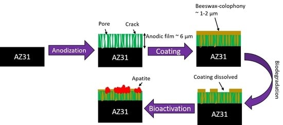
Graphical Abstract

1. Introduction

There have been continuous efforts to develop a biocompatible coating for retarding the fast degradation of magnesium (Mg) alloys for biomedical implant purposes [1,2,3,4,5,6,7,8,9]. The spontaneous degradation of Mg alloys in an aqueous environment means it is well-suited for the application as a temporary implant material. Clinical trials on some commercial products of Mg-based implants, namely BIOTRONIK stents and MAGNEZIX screws, have proved the excellent biocompatibility of Mg alloys as no allergic reaction or health threat were reported [10]. However, a slower biodegradation rate of the implant is necessary to maintain the mechanical integrity of the alloys during the healing period [11,12,13]. A coating serves as an effective barrier to limit contact between the metal and the environment and thus reduces the corrosion rate. The most popular coatings investigated for Mg alloys are calcium phosphate-based, including hydroxyapatite (HA) coatings [14,15,16,17]. High-temperature coating techniques such as plasma spraying, chemical vapor deposition, and sintering are involved in producing dense HA coatings on Mg surfaces. Exposure to elevated temperature influences the microstructure and characteristics of the Mg alloys with a low melting point [18]. The biocompatible organic coatings offer a low-temperature fabrication as well as serve other beneficial functions in drug delivery and interact with the surrounding biomolecules during implantation [19].
The biocompatible polymer coatings, such as polyurethane (PU), polylactide (PLA), and polyglycolide (PGA), were reported to exhibit anti-corrosion and anti-bacterial properties in an in vitro test [1,3,4,9,19]. However, the coatings are unstable and potentially undergo hydrolysis during service, releasing acid products that counteract the biocompatibility properties. The pH reduction in the vicinity of an implant induces unexpected reactions of the surrounding tissues, such as inflammation [20]. A novel beeswax–colophony mixture was synthesized in this work as an alternative biocompatible polymer coating for Mg alloys. Beeswax and colophony are abundant natural resources and are inexpensive, biodegradable, edible, and non-toxic [21]. Beeswax (C15H31COOC30H61) has been used for decades as bone wax to prevent bleeding during orthopedic surgery [22]. Colophony primarily consists of abietic and colophony acids with hydrophobic hydrophenanthrene rings [23]. Due to the excellent hydrophobicity and biocompatibility properties of the colophony, it is used as a material for coating, microencapsulation, and matrix material in medicine. However, there is a lack of research on the beeswax and colophony as a metal coating.
Colophony serves as an adhesive agent for beeswax in the beeswax–colophony coating. The adhesivity and resistivity of the beeswax–colophony coating depend on the ratio of beeswax to colophony. Earlier work in our group [24] revealed that the best composition of beeswax to colophony was 6:4, which gave high stability to the coating in chloride solution. A higher fraction of beeswax to colophony (7:1) led to a reduction in corrosion inhibition performance [25]. The application of beeswax–colophony blend as thick as 400 μm on the inner pipe of a drinking water distribution tank protected the surface from deterioration for a long exposure time, as well as prevented biofouling [26]. However, direct application of the coating on the metal surface led to an easy coating detachment during exposure to a chloride solution. The high surface alkalinity of Mg is not favorable for most organic coatings [27]. An intermediate layer is necessary to enhance the wetting of the coating to the metal surface. Anodization is a standard method of surface treatment for Mg alloys to convert the metal surface into a porous anodic oxide film [28]. The porous structure significantly enhanced the surface area for the final coating deposition. In this work, an anodic film formed in a sodium phosphate solution was used as a precoat layer for beeswax–colophony coating on the AZ31 Mg alloy. The degradation behaviors of the individual and combined treatments of anodization and coating were studied by a weight loss test and electrochemical measurements in physiological Ringer lactate solution. The apatite-forming ability of the anodized and coated specimen was also evaluated by observing the surface composition after 14 days of immersion in Ringer lactate. The NaCl solution used as the test solution in our previous work [24,25] did not give information on the apatite-forming ability of the coated specimen.

2. Materials and Methods

2.1. Specimen Preparation

A rolled plate magnesium alloy AZ31 with a thickness 1 mm was used as a substrate. The AZ31 alloy contained 3 wt% Al and 1 wt% Zn as the main alloying elements, similar to that reported earlier [24]. The AZ31 plate was cut into 1.5 cm × 3.0 cm, but the working area was limited to 5 cm2. The specimen was degreased in acetone followed by ethanol in an ultrasonic bath for 3 min to remove debris. The specimen was then dried in an air stream before further use.

2.2. Anodization

The as-received substrate was pretreated in a mixed acid solution of 10 vol% HNO3-2 vol% H3PO4 for 20 s and then neutralized in 5 wt% NaOH solution at 80 °C for 1 min to remove the natural oxide layer. Anodization proceeded at a constant voltage of 5 V in an alkaline solution of 0.5 M Na3PO4 at 30 °C for 10 min. The current output was recorded using a digital multimeter datalogger (Rigol DM3068, Rigol Tech., Suzhou, China). After anodization, the specimen was cleaned under running water for a few minutes, followed by spraying with DI water and then drying. The anodic film thickness was measured by the coating thickness gauge (Dekko CM-8826FN, Dekko, Seoul, Korea). The average thickness was obtained from 10-point measurements on both the front and rear surfaces.

2.3. Coating Preparation

The beeswax–colophony coating was prepared from natural pure beeswax and colophony blocks. The weight ratio of beeswax:colophony was 6:4 with a total weight of 10 g. The beeswax and colophony were melted at 80 °C in separate beakers, and each was stirred gently for 30 min. The molten beeswax and colophony were then poured into a beaker and stirred again for another 30 min. Two sets of specimens, substrates and anodized, were coated by dipping the specimen in the molten beeswax–colophony mixture at 80 °C for 90 min and then cured in ambient air for 8 h. One set of the anodized specimen was sealed hydrothermally by placing the specimen in boiling water for 1.5 h.

2.4. Characterization

The effect of sealing on the surface morphology of the anodized specimens was studied using a scanning electron microscope (SEM, JEOL-JSM-6390A, JEOL Ltd., Tokyo, Japan) which was equipped with energy dispersive spectroscopy (EDS). For cross-section observation, the anodized specimen was mechanically sliced, followed by grinding to smoothen the surface. The surface was sputtered with gold to reduce charging during SEM observation.

2.5. Electrochemical Tests

The corrosion behavior of the specimens was investigated by performing electrochemical tests, including potentiodynamic and electrochemical impedance spectroscopy (EIS), in Ringer lactate at 37 °C at neutral pH. The composition of Ringer lactate is listed in Table 1. The measurements were performed using a Corrtest CS310 potentiostat (Wuhan Corrtest Instruments Corp., Ltd., Wuhan, China) with a three-electrode configuration: specimen as the working electrode, platinum as the counter electrode, and silver/silver chloride (Ag/AgCl) as the reference electrode. The potentiodynamic polarization test was performed at a potential of 100 mV below the open circuit potential (OCP) up to 300 mV above OCP at a sweep rate of 0.5 mV/s. The specimen was immersed for 20 min prior to the measurement to stabilize the OCP. The EIS measurement was conducted at ±10 mV from OCP in the frequency range of 10−1–105 Hz. All the measurements were repeated on three replicate specimens.

2.6. Weight Loss Test

The weight loss test was carried out by immersing the specimen in commercial Ringer lactate at 37 °C for 14 days. The specimens were soaked individually in a 100 mL solution in a glass bottle in a hanging configuration. The bottle was placed in a circulator water bath with a controllable temperature. The solution was refreshed every other day and at the same time, the specimen was weighed. The beeswax–colophony layer was removed by heating the specimen at 80 °C and then degreased with acetone. The corrosion product was removed using 180 g/L CrO3 solution for 2 min based on the ASM standard [29]. The test was replicated for three specimens. The average corrosion rate of the specimen was obtained by taking an average of the data from three replicate specimens.

3. Results and Discussion

The bilayer investigated in this work consisted of an anodic film grown by anodization for 10 min and a beeswax–colophony layer. The anodic film thickness was 6 ± 0.3 µm, as measured by the coating thickness gauge. The film thickness resulting from anodization of the AZ31 alloy increased linearly from 3 to 15 µm for 5 to 20 min [25]. Anodization longer than 10 min resulted in a thick film which could be easily detached from the surface. The exfoliation of the outermost layer occurred due to the hydration of the film during drying of the specimen under the hot air stream.

3.1. Bilayer Morphology and Composition

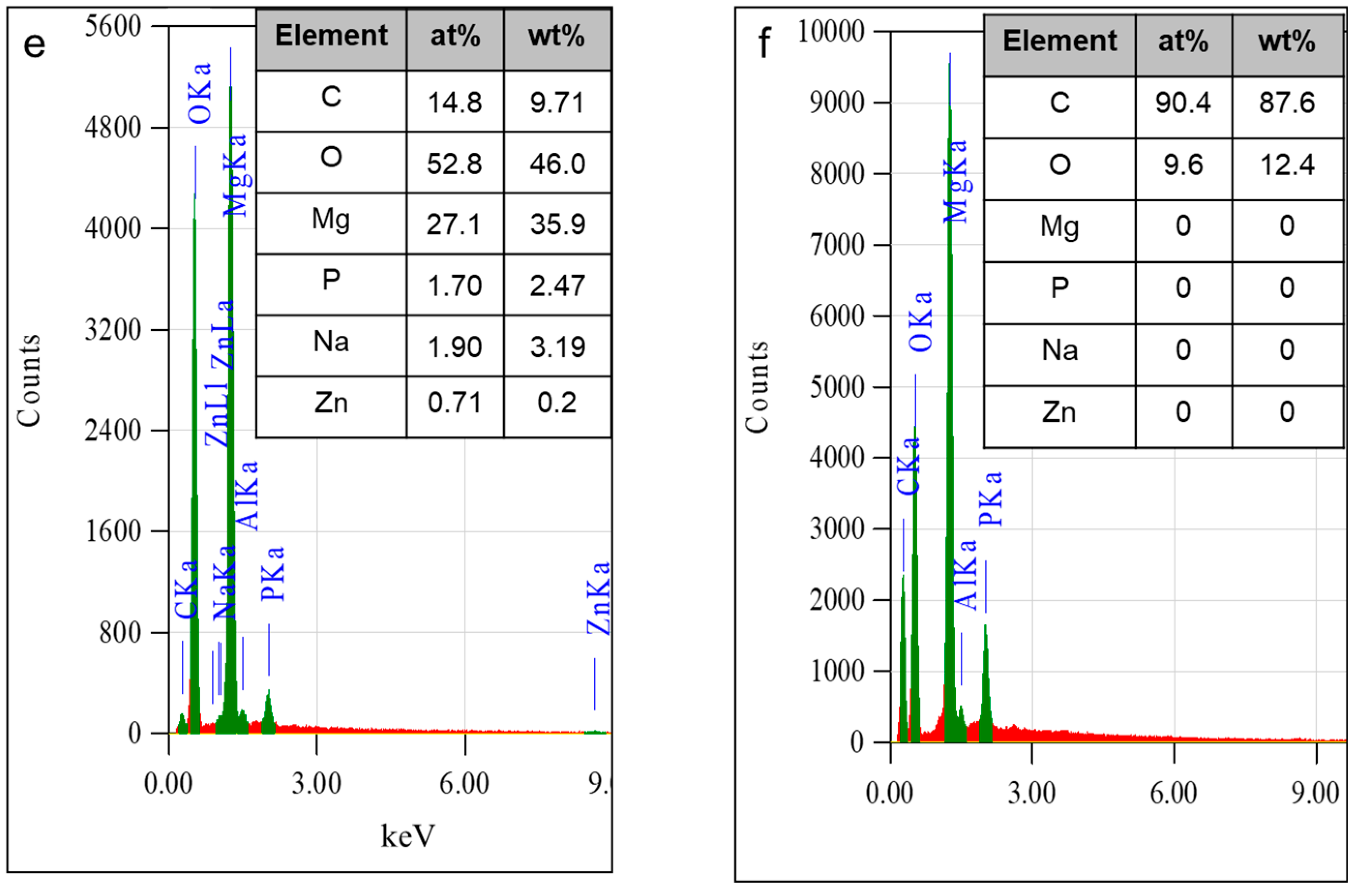
The plane-view and cross-section FE-SEM images of the anodic oxide layer before and after being coated by the beeswax–colophony and the corresponding EDS analysis are shown in Figure 1. The anodic film shown in Figure 1a,b exhibited a porous and cleaved structure typical of a magnesium oxide layer. The anodic film was formed homogeneously on the surface with a thickness of 6 µm, consistent with the resulting thickness measured by the coating thickness gauge. Thicker oxide did not necessarily enhance the corrosion resistance of the specimen as more cracks were developed [24,25]. Thermodynamically, the oxide film formed on Mg is riven due to the significant difference in volume expansion between the metal and the oxide, which resulted in a high Pilling–Bedworth ratio (PBR) [18]. The porous structure of the anodic film yielded a greater surface area for the firm anchorage of the final coating. Figure 1c,d show the surface and cross-section images of the beeswax–colophony filling the defects in the anodic film. The beeswax–colophony infiltrated the pores and cracks in the coating as well as forming a thin layer on top of the anodic surface with a thickness of approximately 1 µm (Figure 1d). The surface layer of the bilayer gave a compact appearance, as shown in Figure 1c. The rugged morphology of the coating was developed due to shrinkage during curing. The coating wetted the anodic film thoroughly, as no clear separation of the film–coating interface was observed in the cross-section image in Figure 1d. The fingerprint characteristic of the beeswax–colophony blend had been analyzed earlier by FTIR and reported in [24]. The spectra confirmed the existence of both beeswax and colophony in the coating, and no additional chemical bonding arose in the spectra attributed to any chemical reaction between the two compounds.

3.2. Electrochemical Corrosion

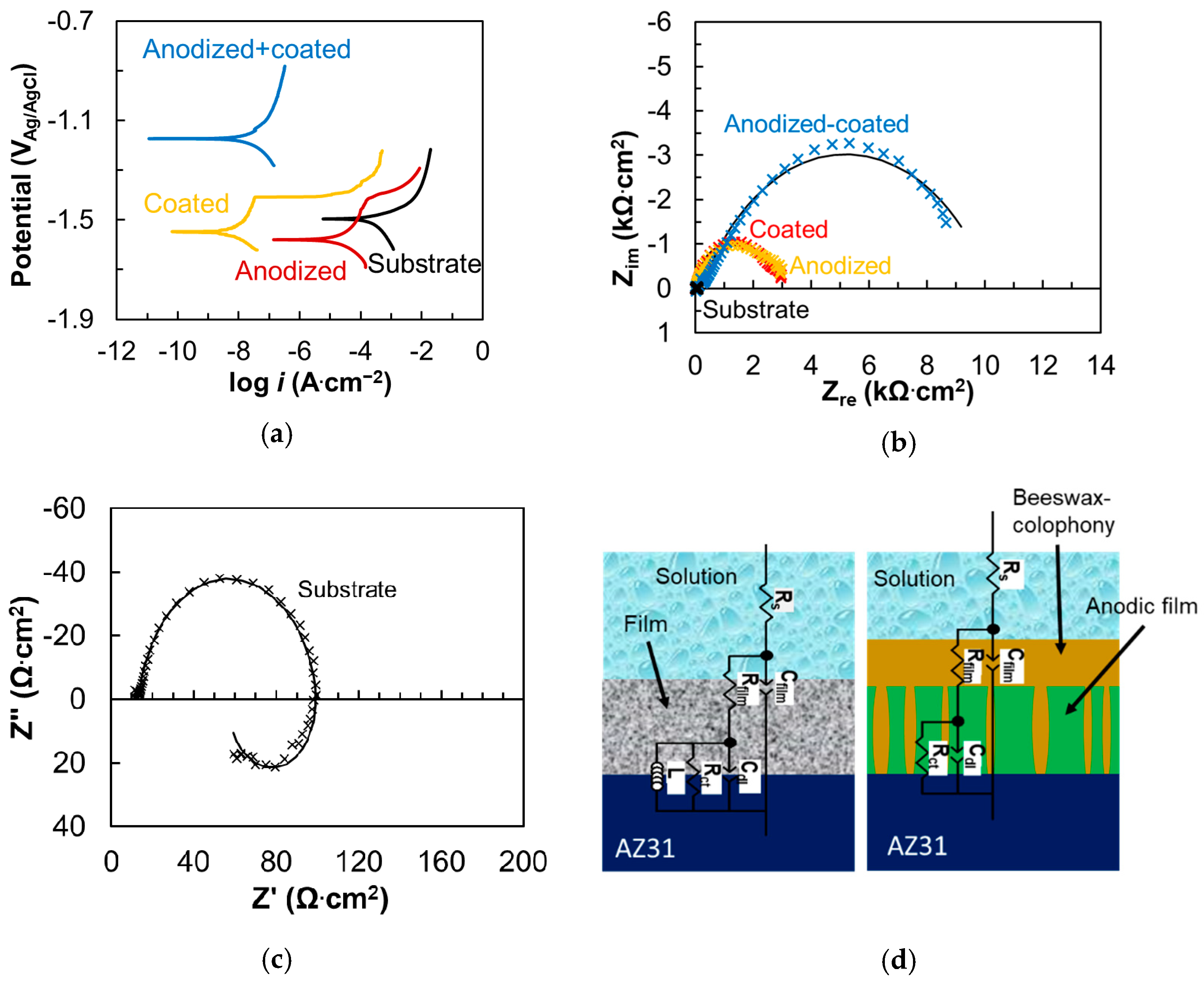
The electrochemical corrosion behavior of the AZ31 specimens in Ringer lactate is demonstrated by the potentiodynamic polarization curves and impedance spectra in Figure 2. Table 2 lists the corrosion potentials and current densities data obtained from the polarization curves in Figure 2a. The solid black curves in Figure 2b are the fitting curves. The impedance data were fitted following the electronic circuits shown in Figure 2d. Rs is solution resistance, Rfilm-Cfilm represents the film impedance, Cdl-Rct represents the double-layer capacitance and charge transfer resistance. An additional inductor, which represented the corrosion of metal, in parallel with the Cp-Rp, exists in the equivalent circuit for the substrate, as shown in Figure 2c. The fitted parameters are tabulated in Table 3. Figure 2a showed that the AZ31 substrate exhibited a corrosion potential of −1.50 VAg/AgCl and a corrosion current density of 5.72 × 10⁻⁴ A·cm−2. The corrosion potential and current density of AZ31 alloy were similar to those reported in Hank’s physiological solution [30]. The individual treatment of anodization or coating, the red and yellow curves in Figure 2a, shifted the corrosion potential of the substrate towards a negative direction accompanied by the reduction in cathodic current density, indicating a cathodic inhibition effect. Suppression of the cathodic activities on the surface by the anodic layer or beeswax–colophony coating led to the depression in the corrosion potential. The beeswax–colophony coating reduced the corrosion current density of the substrate four orders magnitude while the anodic layer gave an order magnitude reduction in corrosion current density. As departed from the corrosion potential, both the curves of the anodized and the coated specimens showed a tendency of passivation up to the pitting potential at −1.41 VAg/AgCl, where the current density began to increase again.
The anodic layer or coating enlarged the impedance spectra of the AZ31 alloy by two orders of magnitude (Figure 2b), confirming the corrosion resistance enhancement. The impedance spectra revealed two semicircles associated with two time-constants. The spectra can be described by the equivalent electrical circuit consisted of two R-C circuits. The first circuit (Rct-Cdl) represented the charge transfer process occurring on the surface, and the second circuit (Rfilm-Cfilm) correlated to the film covering the electrode surface. The film in the substrate referred to the corrosion products. The polarization resistance, which was the sum of film resistance and charge transfer resistance of the substrate, enhanced 100 times in the presence of either the anodic film or the beeswax–colophony layer. Note that the beeswax–colophony layer offered one half times higher film resistance and four times higher charge transfer on the metal surface than the anodic film (Table 3). The result was in line with the polarization data that displayed significantly lower corrosion current density of the specimen coated by the beeswax–colophony layer than the anodic film.
Substantial ennoblement in the corrosion potential was attained on the anodized and coated specimen, as demonstrated by the blue curve in Figure 2. The beeswax–colophony coating uniformly covered the porous anodic film leading to the significant ennoblement in corrosion potential to −1.17 VAg/AgCl and low corrosion current density of 3.19 × 10⁻⁸ A cm−2, as shown in Figure 2a. At such a low corrosion current density, magnesium alloy was considered to be in the passive condition [31]. The corrosion potential of the anodized and coated specimen was much higher than the pitting potential of the AZ31 specimen, indicating a substantial enhancement in the pitting resistance. The inhibition efficiency calculated from the corrosion current density data of the beeswax–colophony layer relative to the single layer anodic film reached the value of 99.9%. The largest diameter of the impedance spectra in Figure 2b, marking the highest corrosion resistance, was also demonstrated by the anodized and coated specimen. The spectra revealed one large capacitive loop at the medium to low-frequency ranges. The loop at the high-frequency range was not resolved as it was overwhelmed by the remarkably high film resistance (995 kΩ cm2), and hence the Cfilm decreased significantly. The beeswax–colophony effectively boosted the corrosion resistance approximately 350 times the anodized specimen. As compared to the bare substrate, the film resistance of the anodized and coated specimen was four orders of magnitude higher (Table 3). The stable bilayer coating effectively suppressed both the cathodic (hydrogen evolution) and anodic (dissolution of Mg) reactions on the surface. Beeswax and colophony were stable in their solid form on the surface. The melting points were 62 °C for beeswax [32] and 70−72 °C for colophony [33]. The test solution was kept at 37 °C, far below the melting point of the beeswax–colophony components. Therefore, the beeswax–colophony layer was stable and attached well to the porous anodic film during the entire test period.
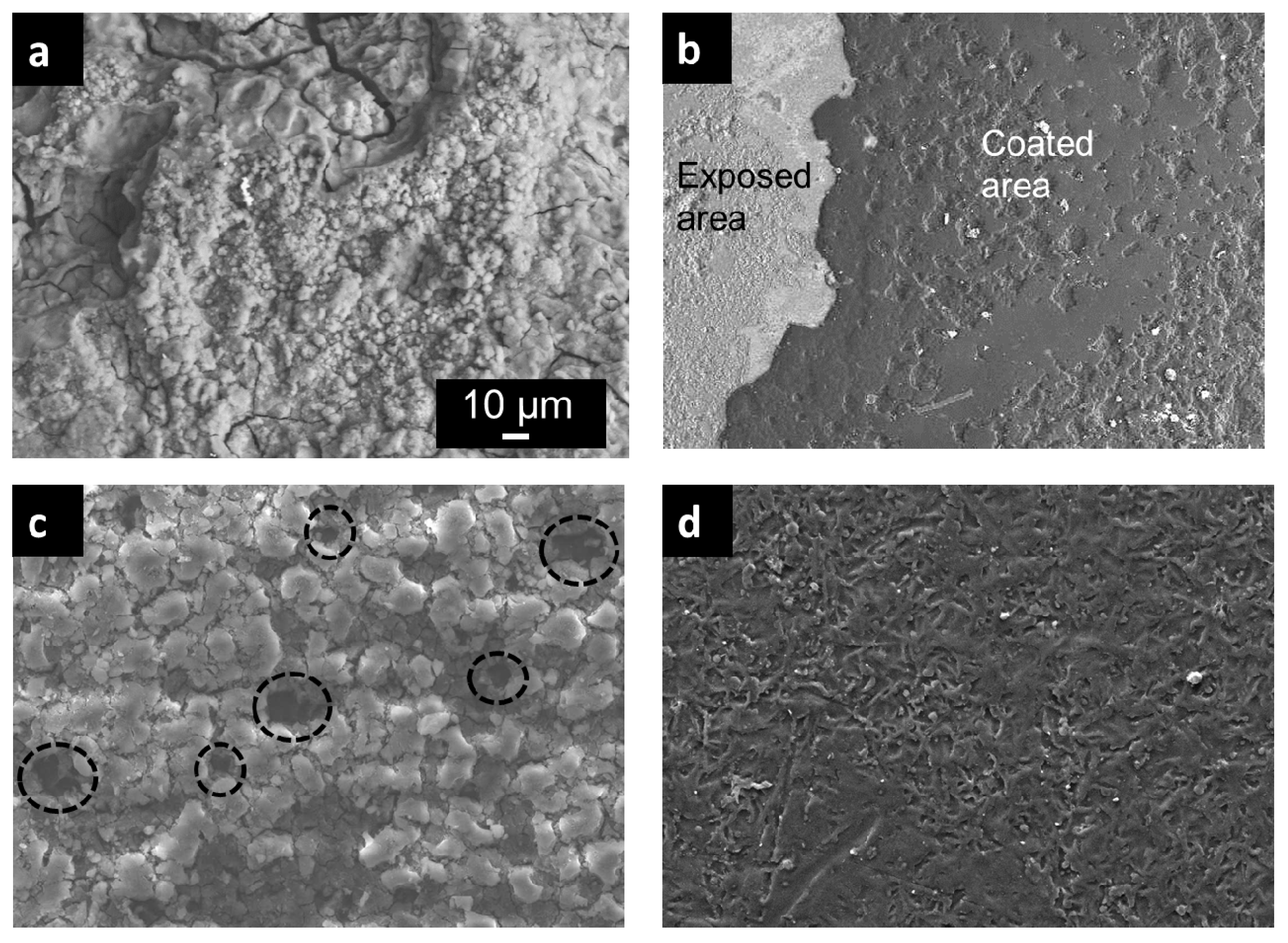
The corrosion morphology after the polarization test is displayed in Figure 3. The substrate experienced severe deterioration giving a rough and random crack morphology, as shown in Figure 3a. The corrosion product with micrograin structure was accumulated on the surface. The morphology was a typical structure for magnesium hydroxide complexes [34]. In the beeswax–colophony-coated specimen, the coating was detached at few local areas, exposing the underlying substrate (Figure 3b). The exposed area showed a superficial corrosion morphology which was milder than that of the bare substrate in Figure 3a. The corrosion attack experienced by the anodized specimen was more localized in the form of pit, which was observed randomly on the surface. The pits with a diameter of about 10 µm are marked by the dashed circle in Figure 3c. The only specimen that remained intact after the polarization test was the one that covered by the bilayer, as displayed in Figure 3d. The rough structure of the coating was likely due to dehydration of the coating during drying after the test. Confirming the polarization curves in Figure 2, the bilayer-coated specimen provided the best corrosion protection as compared to the individual anodization or coating.

3.3. Weight Loss Behavior

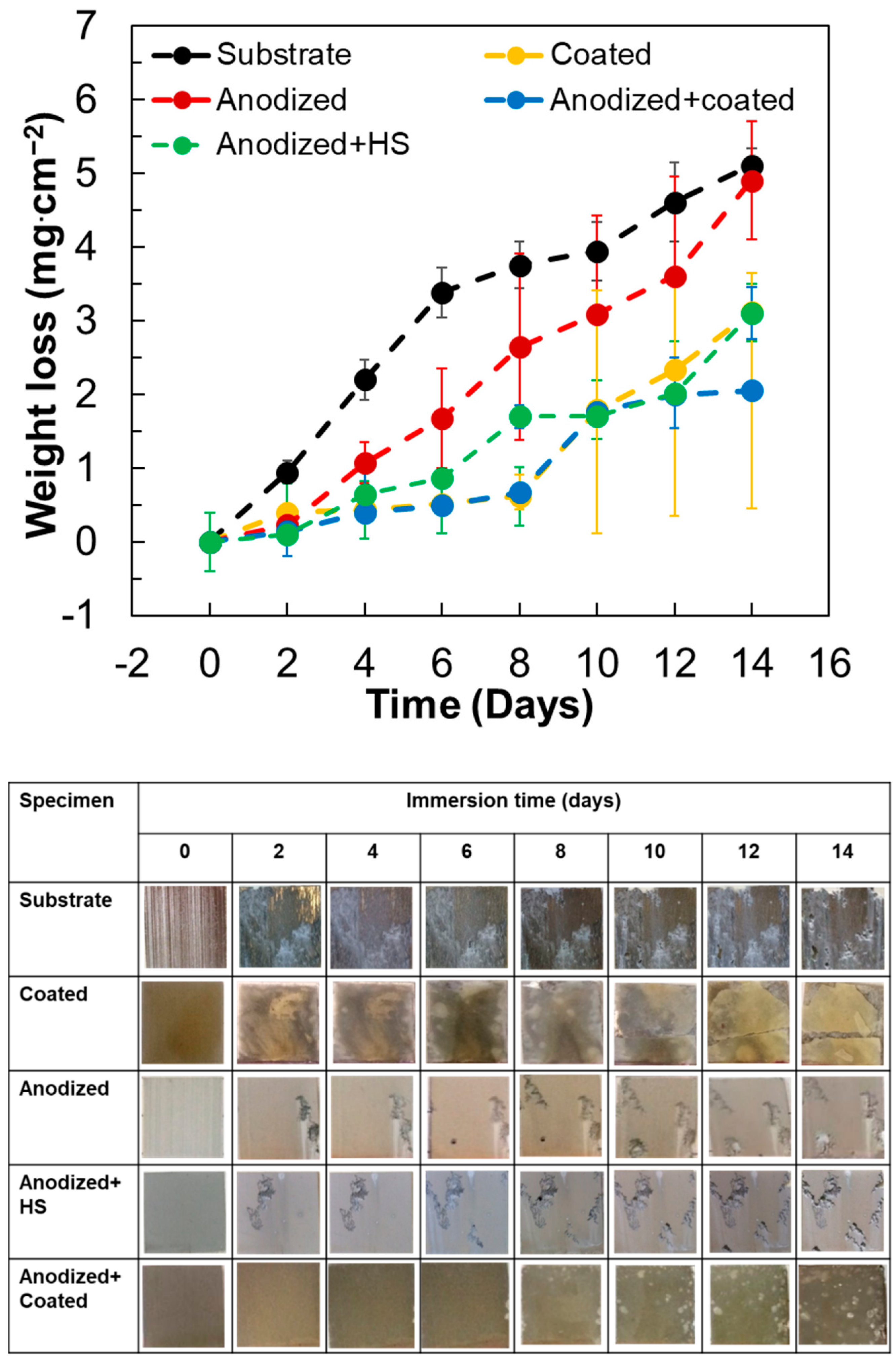
The corrosion behavior of the specimens for 14 days of exposure in Ringer lactate solution was examined using the weight loss test. The weight loss data and the specimen appearance after the immersion are displayed in Figure 4. The error bar in the graph indicated the standard deviation of three replicate specimens. The anodized and coated specimen exhibited the lowest weight loss curve (blue curve) relative to the other specimens during the entire immersion time. From day 0 to day 8, the weight loss of the anodized and coated specimen was relatively low, below 0.5 mg/cm2. Coating damage in the form of blisters was visible as a few white spots at the specimen edges (Figure 4). The solution was able to penetrate the coating at the defects and initiated local corrosion, undermining the coating, creating blisters. The edges were the weak point of a rolled plate alloy where defects were accumulated and attacked easier by corrosion. The mass loss in the initial immersion time was attributed to the detachment of the bilayer at blisters. The number of blisters on the surface grew significantly at prolonged soaking time. The specimen edges, particularly the right-hand side in the image, began to dissolve at day 10 and became worsened at a prolonged exposure time, yielding to a rough edge. Consequently, the weight loss jumped three times to 1.5 mg/cm2 on day 10 and further increased to 1.9 mg/cm2 and 2.0 mg/cm2 after 12 and 14 days, respectively. The surface appearance demonstrated superior corrosion protection served by the bilayer until 14 days, among other specimens that showed severe damage at day 2 of immersion. The average weight loss of the bilayer-coated specimen was 0.07 mg/cm2/day. As compared to the substrate with an average loss of 0.24 mg/cm2/day, the anodized and coated specimen exhibited approximately three times lower mass loss.
Observation in the laboratory revealed no visible gas release on the treated specimens (anodized, coated, anodized-coated), in contrast to the vigorous hydrogen gas released on the bare substrate as the specimen was immersed into the solution. The bare substrate exhibited a linear increase in mass loss from 0 to 6 days with a high rate of 0.57 mg/cm2/days, as displayed by the black curve in Figure 4. On day 6, the metal dissolution already reached 3.4 mg/cm2. The entire surface of the bare specimen was corroded within 2 days, and the metallic surface turned grey. After 8 days, the loss rate decreased to 0.24 mg/cm2/days, leading to the maximum mass loss of 5.11 mg/cm2 at 14 days. The corrosion product, which appeared as a grey deposit covering the entire surface of the alloy, slowed down the mass loss to some extent. Pit, which was visible as black spots, was also viewed after 2 days of immersion and grew in number and size at a prolonged time. The specimen was severely corroded after 12 days of immersion, resulting in the corrosion product precipitation at the bottom of the bottle. The calculated corrosion rate of the bare substrate in Ringer lactate was approximately 1.47 mmpy. The rate was similar to that reported for a bare AZ31 alloy in chloride solution [13].
Single treatment of anodization or coating was not able to inhibit the severe degradation of the AZ31 substrate. The anodized specimen showed a linear increase in mass loss through the entire soaking time, as displayed in Figure 4. The final mass loss of the anodized specimen (red curve) was nearly as high as that of the substrate (black curve). In the anodized specimen, corrosion was propagated in the vertical direction as opposed to the bare substrate that showed general corrosion. Pits were initiated randomly after 2 days of immersion. The deep attack may cause a serious threat to the mechanical integrity of the alloy. The sealing of the anodic layer by hydrothermal treatment following anodization did not improve the corrosion resistance of the anodized specimen. Hydrothermal sealing is a common technique to seal pores in an anodized specimen, which was carried out simply by throwing the specimen in boiling water right after anodization. The corrosion type on the anodized and HS specimen was similar to that of the anodized specimen, as shown in Figure 4. The specimen coated by beeswax–colophony showed a relatively low mass loss up to 8 days of immersion (yellow curve in Figure 4). However, the surface changed from a yellowish to dark appearance, indicating undermining corrosion attacked within 2 days. The previous result revealed [24] that blisters appeared randomly on the coated specimen after 24 h immersion in 0.9 wt% NaCl solution. Penetration of the coating by the solution occurred through defects, particularly along the edges. The corrosion product was trapped under the coating until the coating was disintegrated at day 10, leading to a significant mass loss increase. Afterward, the mass loss increased linearly until the end of the measurement. The detachment of the coating in many areas on the surface enhanced the corrosion rate of the uncovered surface.
The improvement of corrosion resistance afforded by the bilayer coating on the AZ31 specimen exceeds those offered by other organic coatings reported elsewhere [1,2,3,4,5,6,7,8,9]. Compared to the more advanced technique, plasma electrolytic oxidation (PEO), which enhances the corrosion resistance in the order of 100−1000 times [14,35,36], the bilayer offered higher a degree of protection. The significant depression of corrosion activities provided by the bilayer coating assured the absence of rapid hydrogen gas evolution and maintained the mechanical integrity of the alloy during initial exposure in the physiological solution. In contrast to the anodic film resulted from PEO, which contributed to the increase in surface hardness, the bilayer is expected not to change the mechanical properties of the surface.
The apatite-forming ability of the bilayer in Ringer lactate was evaluated by observing the surface morphology and composition of the anodized-coated specimen after 14 days of immersion. Figure 5 shows the surface morphology and the corresponding EDS maps for Mg, O, P, and Ca together with the EDS spectra of the anodized–coated specimens after 14 days immersion in Ringer lactate. The FE-SEM image in Figure 5a shows a rugged structure due to the local detachment of coating. The higher magnification image of the exposed anodic film inside the rectangular area in Figure 5a is shown in Figure 5b. The exposed anodic film exhibited a grain structure similar to that of Figure 3c. The EDS maps of the anodic film displayed strong Mg and O signals and weak signals for P and Ca. The spectra and quantitative data in Figure 5g confirmed the composition of the anodic film composed mainly of Mg and O. The alloying element Al was enriched on the surface (7.96 at%) due to the selective corrosion of Mg. Ca was detected on the surface at a concentration of 4.63 at%, while the concentration of P was 2.75 at%. P and Ca are the main composition of apatite (Ca5(PO4)3(OH)). The ratio of Ca/P from the EDS analysis in Figure 5g was 1.68. The ratio is close to that of stoichiometry apatite, 1.67 [37]. The maps for P and Ca in Figure 3d,f revealed a strong signal at a similar area, indicating the presence of these elements together. The anodic film contained P compounds as resulting from the incorporation of the substance from the anodization bath (Na3PO4). Corrosion of Mg metal under the exposed film induced local alkalization as a result of hydrogen gas release. The alkali environment attracted positive ions to precipitate in the porous oxide film. Ca ions from the Ringer lactate were deposited on the anodic film. The Ca–P compound is a precursor for the nucleation of bone mineral apatite.
Considering the remarkable corrosion resistance offered by the bilayer coating on the AZ31 alloy and the high apatite-forming ability, the bilayer shows promise as a coating for magnesium-based implants. Moreover, the bilayer coating process is relatively simple and inexpensive. The beeswax and colophony are abundant natural resources in Indonesia. The beeswax–colophony coating plays an excellent role as a sacrificial layer, which protects the underlying anodic film during the first two weeks of immersion time. The high apatite-forming ability of the anodic film promotes the deposition of an apatite layer once the outer layer is degraded. Nevertheless, further study on the long-term behavior of the bilayer coating is necessary to confirm the surface bioactivity and corrosion behavior in physiological solution.

4. Conclusions

The corrosion behavior of the bilayer-coated AZ31 alloy in Ringer lactate solution had been investigated through the electrochemical method and weight loss test. The following conclusions were drawn:
  • The electrochemical test showed that the bilayer, which consisted of anodic film and beeswax–colophony, enhanced the corrosion resistance of the AZ31 alloy substantially. The polarization test demonstrated four orders of magnitude lower current density and the EIS analysis revealed four orders of magnitude higher impedance of the bilayer coating than that of the substrate.
  • The top organic coating acted as an excellent barrier for the metal surface as the underlying porous structure of the anodic film allowed strong anchorage of the beeswax–colophony layer. The anodic film itself was not able to inhibit the solution penetration leading to a localized type of corrosion, as revealed from the corrosion morphology. Similarly, direct application of the beeswax–colophony on the metal surface was not able to withstand undermining corrosion, which yielded to local coating detachment. The molten beeswax–colophony effectively blocked the pores and defects in the anodic film when applied as the overcoating, resulting in a remarkable improvement of corrosion resistance of the AZ31 alloy. The bilayer mostly remained attached on the surface except at a few localized blisters after 14 days exposure in Ringer lactate.
  • Surface investigation and EDS analysis indicated the bilayer exhibited high apatite-forming ability, particularly the exposed anodic film at which the beeswax–colophony layer was peeled off. EDS detected a Ca–P compound with a Ca/P ratio of 1.68 on the exposed anodic film. The remarkable improvement of corrosion resistance and the high apatite-forming ability of the bilayer shows promise as a coating for biomedical implant application.

Author Contributions

Conceptualization, A.A.; methodology, A.A.; validation, A.A., formal analysis, A.A., M.F.F., and M.D.G.; investigation, M.F.F., and M.D.G.; resources, A.A.; writing—original draft preparation, A.A.; writing—review and editing, A.A.; visualization, A.A., M.F.F., and M.D.G.; supervision, A.A.; funding acquisition, A.A. All authors have read and agreed to the published version of the manuscript.

Funding

This research was funded by Universitas Indonesia through PUTI Q2 Grant, grant number BA-1368/UN2.RST/PPM.00.03.01/2020.

Institutional Review Board Statement

Not applicable.

Informed Consent Statement

Not applicable

Data Availability Statement

All the original data generated in this research are available.

Acknowledgments

Authors would like to acknowledge Hasna Labibah, ST for helping with the electrochemical results analysis.

Conflicts of Interest

The authors declare no conflict of interest.

References

  1. Kim, Y.-K.; Jang, Y.-S.; Kim, S.-Y.; Lee, M.-H. Functions achieved by the hyaluronic acid derivatives coating and hydroxide film on bio-absorbed Mg. Appl. Surf. Sci. 2019, 473, 31–39. [Google Scholar] [CrossRef]
  2. Santos, L.R.; Marino, C.E.; Riegel-Vidotti, I.C. Silica/chitosan hybrid particles for smart release of the corrosion inhibitor benzotriazole. Eur. Polym. J. 2019, 115, 86–98. [Google Scholar] [CrossRef]
  3. Vahabi, H.; Rad, E.R.; Parpaite, T.; Langlois, V.; Saeb, M.R. Biodegradable polyester thin films and coatings in the line of fire: The time of polyhydroxyalkanoate (PHA)? Prog. Org. Coat. 2019, 133, 85–89. [Google Scholar] [CrossRef]
  4. Saji, V.S. Organic conversion coatings for magnesium and its alloys. J. Ind. Eng. Chem. 2019, 75, 20–37. [Google Scholar] [CrossRef]
  5. Battegazzore, D.; Frache, A.; Carosio, F. Sustainable and high performing biocomposites with chitosan/sepiolite layer-by-layer nanoengineered interphases. ACS Sustain. Chem. Eng. 2018, 6, 9601–9605. [Google Scholar] [CrossRef]
  6. Castro, Y.; Durán, A. Control of degradation rate of Mg alloys using silica sol–gel coatings for biodegradable implant materials. J. Sol-Gel Sci. Technol. 2018, 90, 198–208. [Google Scholar] [CrossRef]
  7. Chang, W.; Qu, B.; Liao, A.; Zhang, S.; Zhang, R.; Xiang, J. In vitro biocompatibility and antibacterial behavior of anodic coatings fabricated in an organic phosphate containing solution on Mg–1.0Ca alloys. Surf. Coat. Technol. 2016, 289, 75–84. [Google Scholar] [CrossRef]
  8. Wu, H.; Shi, Z.; Zhang, X.; Qasim, A.M.; Xiao, S.; Zhang, F.; Wu, Z.; Wu, G.; Ding, K.; Chu, P.K. Achieving an acid resistant surface on magnesium alloy via bio-inspired design. Appl. Surf. Sci. 2019, 478, 150–161. [Google Scholar] [CrossRef]
  9. Hong, L.; Shen, M.; Fang, J.; Wang, Y.; Bao, Z.; Bu, S.; Zhu, Y. Hyaluronic acid (HA)-based hydrogels for full-thickness wound repairing and skin regeneration. J. Mater. Sci. Mater. Med. 2018, 29, 150. [Google Scholar] [CrossRef]
  10. Chen, Y.; Xu, Z.; Smith, C.; Sankar, J. Recent advances on the development of magnesium alloys for biodegradable implants. Acta Biomater. 2014, 10, 4561–4573. [Google Scholar] [CrossRef]
  11. Waksman, R.; Erbel, R.; Di Mario, C.; Bartunek, J.; de Bruyne, B.; Eberli, F.R.; Erne, P.; Haude, M.; Horrigan, M.; Ilsley, C.; et al. Early- and long-term intravascular ultrasound and angiographic findings after bioabsorbable magnesium stent implantation in human coronary arteries. JACC Cardiovasc. Interv. 2009, 2, 312–320. [Google Scholar] [CrossRef] [Green Version]
  12. Li, Z.; Gu, X.; Lou, S.; Zheng, Y. The development of binary Mg–Ca alloys for use as biodegradable materials within bone. Biomaterials 2008, 29, 1329–1344. [Google Scholar] [CrossRef] [PubMed]
  13. Song, G. Control of biodegradation of biocompatable magnesium alloys. Corros. Sci. 2007, 49, 1696–1701. [Google Scholar] [CrossRef]
  14. Anawati; Asoh, H.; Ono, S. Enhanced uniformity of apatite coating on a PEO film formed on AZ31 Mg alloy by an alkali pretreatment. Surf. Coat. Technol. 2015, 272, 182–189. [Google Scholar] [CrossRef]
  15. Brady, M.P.; Fayek, M.; Leonard, D.N.; Meyer, H.M.; Thomson, J.K.; Anovitz, L.M.; Rother, G.; Song, G.-L.; Davis, B. Tracer Film Growth Study of the Corrosion of Magnesium Alloys AZ31B and ZE10A in 0.01% NaCl Solution. J. Electrochem. Soc. 2017, 164, C367–C375. [Google Scholar] [CrossRef]
  16. Srinivasan, P.B.; Liang, J.; Blawert, C.; Störmer, M.; Dietzel, W. Characterization of calcium containing plasma electrolytic oxidation coatings on AM50 magnesium alloy. Appl. Surf. Sci. 2010, 256, 4017–4022. [Google Scholar] [CrossRef] [Green Version]
  17. Gao, Y.; Yerokhin, A.; Matthews, A. Deposition and evaluation of duplex hydroxyapatite and plasma electrolytic oxidation coatings on magnesium. Surf. Coat. Technol. 2015, 269, 170–182. [Google Scholar] [CrossRef]
  18. Pekguleryuz, M.; Kainer, K.; Kaya, A. Fundamentals of Magnesium Alloy; Woodhead Publishing Ltd.: Cambridge, UK, 2013. [Google Scholar]
  19. Wang, C.; Yi, Z.; Sheng, Y.; Tian, L.; Qin, L.; Ngai, T.; Lin, W. Development of a novel biodegradable and anti-bacterial polyurethane coating for biomedical magnesium rods. Mater. Sci. Eng. C 2019, 99, 344–356. [Google Scholar] [CrossRef] [PubMed]
  20. Li, L.; Gao, J.; Wang, Y. Evaluation of cyto-toxicity and corrosion behavior of alkali-heat-treated magnesium in simulated body fluid. Surf. Coat. Technol. 2004, 185, 92–98. [Google Scholar] [CrossRef]
  21. Fratini, F.; Cilia, G.; Turchi, B.; Felicioli, A. Beeswax: A minireview of its antimicrobial activity and its application in medicine. Asian Pac. J. Trop. Med. 2016, 9, 839–843. [Google Scholar] [CrossRef]
  22. Sudmann, B.; Bang, G.; Sudmann, E. Histologically verified bone wax (beeswax) granuloma after median sternotomy in 17 of 18 autopsy cases. Pathology 2006, 38, 138–141. [Google Scholar] [CrossRef]
  23. Yadav, B.K.; Gidwani, B.; Vyas, A. Rosin: Recent advances and potential applications in novel drug delivery system. J. Bioact. Compat. Polym. 2015, 31, 111–126. [Google Scholar] [CrossRef]
  24. Gumelar, M.D.; Putri, N.A.; Anggaravidya, M.; Anawati, A. Corrosion behavior of biodegradable material AZ31 coated with beeswax-colophony resin. In AIP Conference Proceedings; AIP Publishing LLC: Melville, NY, USA, 2018; Volume 1964. [Google Scholar] [CrossRef] [Green Version]
  25. Fitriana, M.F.; Anawati, A. Remarkable improvement in corrosion resistance of anodized AZ31 alloy by sealing with beeswax-colophony resin. J. Phys. Conf. Ser. 2019, 1191, 012032. [Google Scholar] [CrossRef]
  26. Abdikheibari, S.; Parvizi, R.; Moayed, M.H.; Zebarjad, S.M.; Sajjadi, S.A. Beeswax-colophony blend: A novel green organic coating for protection of steel drinking water storage tanks. Metals 2015, 5, 1645–1664. [Google Scholar] [CrossRef] [Green Version]
  27. Song, G.-L.; Shi, Z. Corrosion mechanism and evaluation of anodized magnesium alloys. Corros. Sci. 2014, 85, 126–140. [Google Scholar] [CrossRef] [Green Version]
  28. Murakami, K.; Hino, M.; Nakai, K.; Kobayashi, S.; Saijo, A.; Kanadani, T. Mechanism of corrosion protection of anodized magnesium alloys. Mater. Trans. 2008, 49, 1057–1064. [Google Scholar] [CrossRef] [Green Version]
  29. Avedesian, M.M.; Baker, H. ASM Specialty Handbook: Magnesium and Magnesium Alloys; ASM International, 1999; Available online: https://books.google.co.id/books?id=0wFMfJg57YMC (accessed on 25 April 2017).
  30. Zong, Y.; Yuan, G.; Zhang, X.; Mao, L.; Niu, J.; Ding, W. Comparison of biodegradable behaviors of AZ31 and Mg–Nd–Zn–Zr alloys in Hank’s physiological solution. Mater. Sci. Eng. B 2012, 177, 395–401. [Google Scholar] [CrossRef]
  31. Song, G.L. Corrosion of magnesium (Mg) alloys: Concluding remarks. In Corrosion of Magnesium Alloys; Woodhead Publishing: Cambridge, UK, 2011; pp. 615–617. [Google Scholar] [CrossRef]
  32. Buchwald, R.; Breed, M.D.; Greenberg, A.R. The thermal properties of beeswaxes: Unexpected findings. J. Exp. Biol. 2008, 211, 121–127. [Google Scholar] [CrossRef] [PubMed] [Green Version]
  33. Edwards, H.; Farwell, D.; Daffner, L. Fourier-transform Raman spectroscopic study of natural waxes and resins. I. Spectrochim. Acta Part A Mol. Biomol. Spectrosc. 1996, 52, 1639–1648. [Google Scholar] [CrossRef]
  34. Atrens, A.; Liu, M.; Abidin, N.I.Z. Corrosion mechanism applicable to biodegradable magnesium implants. Mater. Sci. Eng. B 2011, 176, 1609–1636. [Google Scholar] [CrossRef]
  35. Anawati, A.; Asoh, H.; Ono, S. Effects of alloying element ca on the corrosion behavior and bioactivity of anodic films formed on AM60 Mg alloys. Materials 2016, 10, 11. [Google Scholar] [CrossRef] [PubMed]
  36. Echeverry-Rendon, M.; Duque, V.; Quintero, D.; Robledo, S.M.; Harmsen, M.C.; Echeverria, F. Improved corrosion resistance of commercially pure magnesium after its modification by plasma electrolytic oxidation with organic additives. J. Biomater. Appl. 2018, 33, 725–740. [Google Scholar] [CrossRef] [PubMed]
  37. Lu, X.; Leng, Y. Theoretical analysis of calcium phosphate precipitation in simulated body fluid. Biomaterials 2005, 26, 1097–1108. [Google Scholar] [CrossRef] [PubMed]
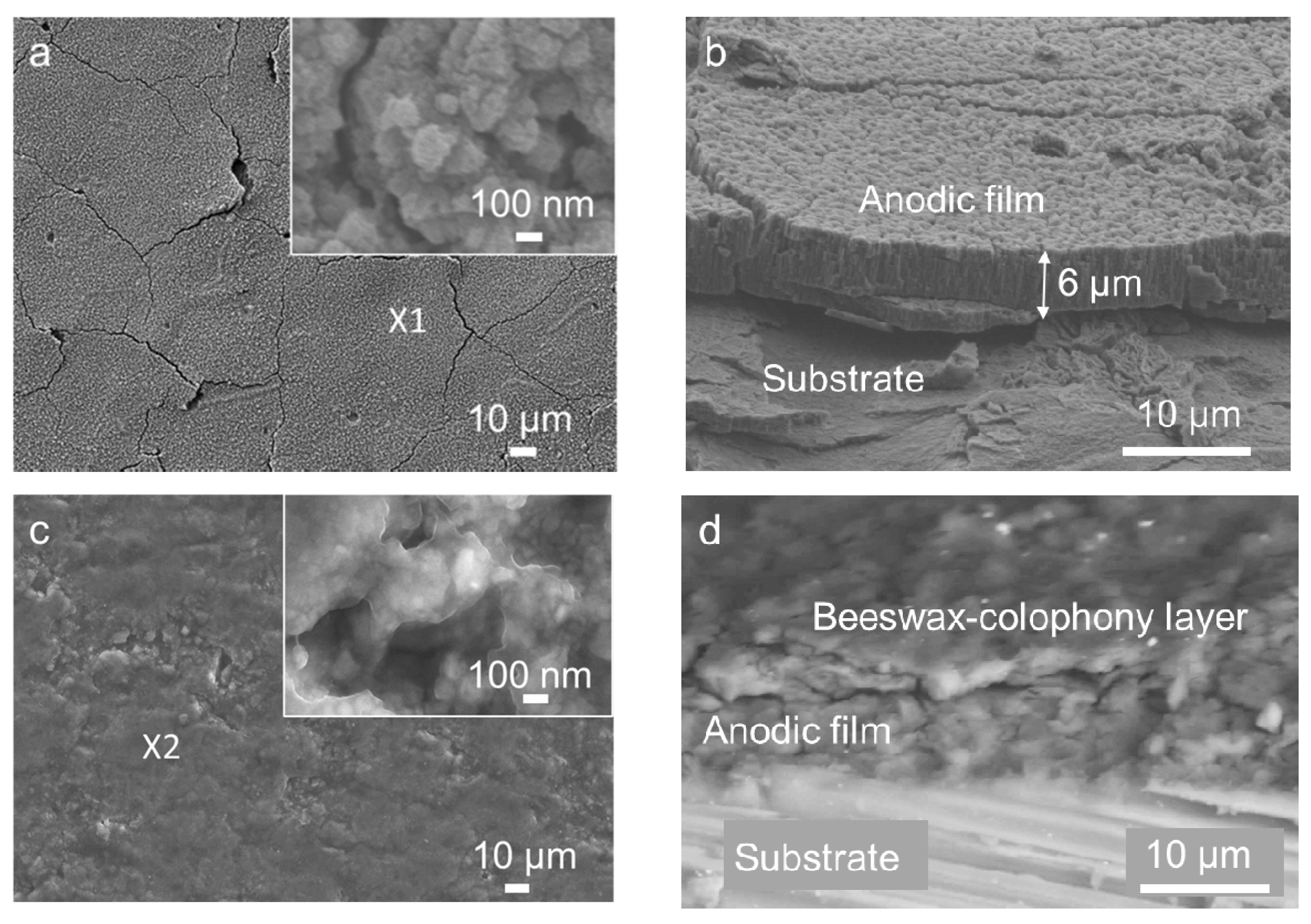
Figure 1. FE-SEM images of (a) surface and (b) cross-section of the anodic film, (c,d) the corresponding morphology after being coated by the beeswax–colophony, and (e,f) the EDS elemental composition of spot marked X1 in image (a) and X2 in image (c), respectively.
Coatings 11 00564 g001aCoatings 11 00564 g001b
Figure 2. (a) Potentiodynamic polarization curves and (b) the impedance spectra of the AZ31 specimens, (c) enlargement of impedance spectra of the substrate in Ringer lactate at 37 °C, and (d) the equivalent circuit electronic model.
Coatings 11 00564 g002
Figure 3. The corrosion morphology after polarization test for (a) substrate, (b) coated, (c) anodized, and (d) anodized–coated specimens. The scale in image (a) applied to all images.
Coatings 11 00564 g003
Figure 4. Weight loss data of AZ31 specimens for 14 days immersion in Ringer lactate solution at 37 °C and the surface appearance.
Coatings 11 00564 g004
Figure 5. (a,b) FE-SEM image of the anodized–coated specimen, (cf) the corresponding EDS maps of image (b) for elements Mg, P, O, and Ca, and (g) the EDS spectra together with the percentage of the element composition after 14 days immersion in Ringer lactate at 37 °C.
Coatings 11 00564 g005
Table 1. Composition of Ringer lactate.
CompoundConcentration (g/L)
NaCl6.0
KCl0.3
CaCl20.2
NaC3H5O33.1
Table 2. Corrosion potentials and current densities values from the polarization curves in Figure 2.
SpecimenEcorr (VAg/AgCl)Icorr (A·cm−2)
Substrate−1.505.72 × 10−4
Anodized−1.583.40 × 10−5
Coated−1.552.54 × 10−8
Anodized + Coated−1.173.19 × 10−8
Table 3. EIS fitted parameters.
SpecimenRs
(Ω cm2)
Rfilm
(Ω cm2)
Cfilm
−1 Sn cm−2)
n1Cdl
−1 Sn cm−2)
n2Rct
(Ω cm2)
L1
(H)
Substrate13.0043.334.31 × 10−50.916.63 × 10−60.9943.8517.67
Anodized18.7429001.94 × 10−50.750.86 × 10−60.99145010.97
Coated12.2848091.39 × 10−50.760.37 × 10−60.805328-
Anodized + coated20.00995,0000.02 × 10−50.700.09 × 10−60.904001-
Publisher’s Note: MDPI stays neutral with regard to jurisdictional claims in published maps and institutional affiliations.