Abstract
In this study, the arc evaporation of pure graphite and composite cathodes with small amounts of metals (Mo, Fe) or nonmetals (B, Si) was investigated by means of a laser-arc process. Both specific aspects of the arc evaporation and the effects on the deposition of the doped and undoped carbon coatings were studied. The deposition rate, the chemical composition and the mechanical properties of the generated films were evaluated. In addition, the dependence of the deposition rate and the composition on the height position of the substrates in relation to the cathode were also the subject of the investigations. Finally, the erosion rate and the arc spot behavior on the cathode were analyzed. It is shown that homogeneously doped (t)a-C:X coatings can be reliably synthesized with the laser-arc technique. There are differences in the various properties of the coatings and the deposition rate. The latter is attributed in particular to the erosion behavior of the cathodes.
1. Introduction
Tetrahedral amorphous carbon (ta-C) coatings have found a wide range of industrial applications, e.g., for tribological components, for cutting tools and in magnetic storage devices, due to the outstanding combination of several properties, such as high hardness, high Young’s modulus, chemical inertness, good tribological behavior and special optical properties [1,2,3]. The deposition processes of carbon coatings are well understood, and comprehensive studies have been undertaken by Robertson or Schultrich [2,4]. Significantly, the cathodic arc evaporation of carbon is an appropriate process for the deposition of ta-C due to its high deposition rate, high ionization and the optimal energy range of the ions [5]. Limitations to the use of ta-C coatings are mainly due to the macroparticle emission [6] that occurs during the evaporation of graphite cathodes. To overcome this problem, filter systems [1] or post-treatment processes [7] can be utilized to minimize the effect of macroparticles and the resulting growth defects. An alternative way to minimize the macroparticle erosion itself is given by Kandah et al. [6,8,9]. In those works, the cathode material is optimized with regard to graphite grain size, the density of the graphite cathode and pore size (distribution), as well as the electrical resistivity of the graphite material. By optimizing these parameters, the arc spot velocity on the cathode surface is increased, leading to a reduction in the number of emitted macroparticles.
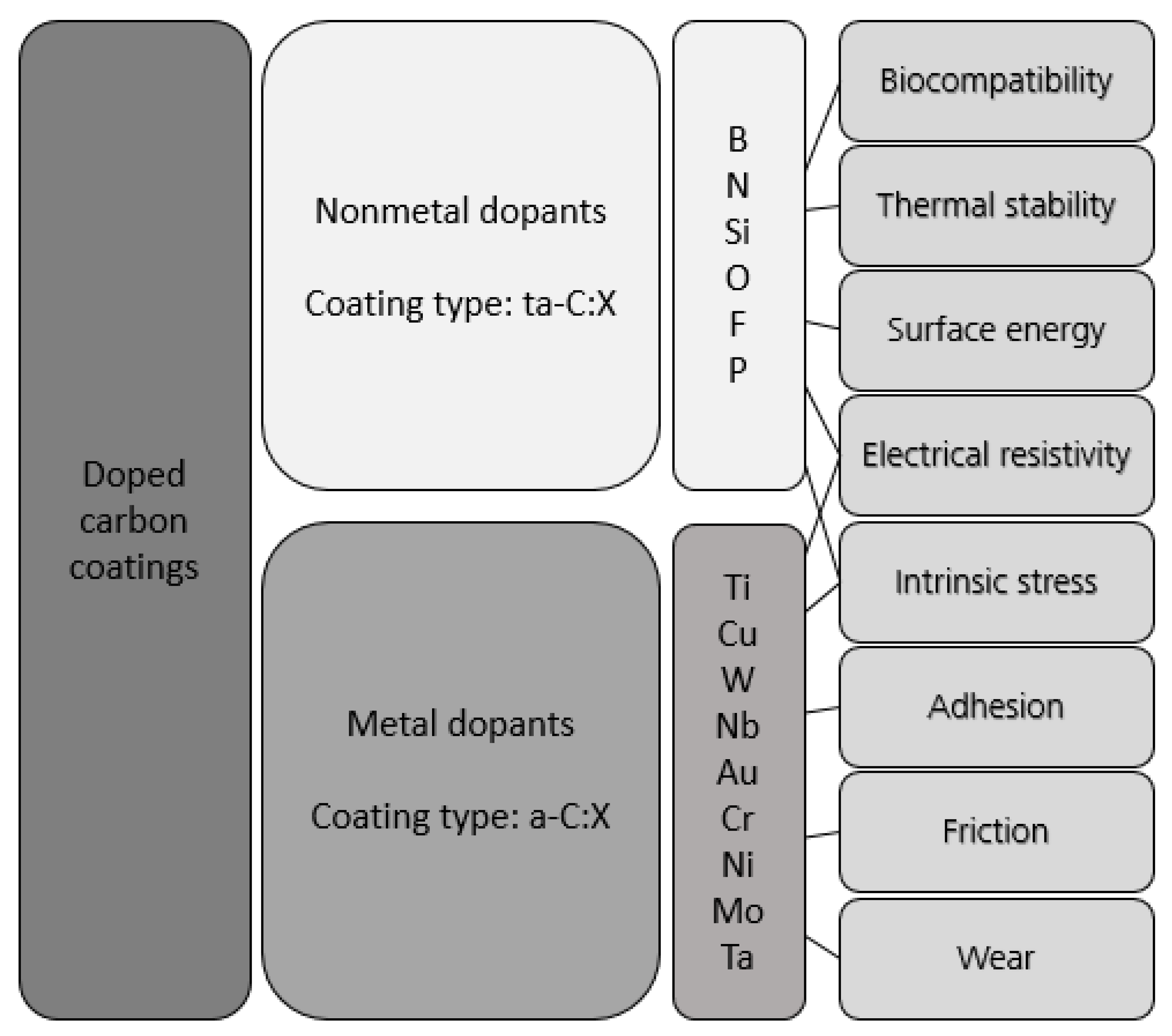
The doping of carbon coatings is a promising way to tailor coatings with regard to specific properties (see Figure 1). Several authors [2,10,11,12,13] investigate the effect of cathode modification and doping elements on the deposition and properties of carbon coatings, whereby the studies from Sánchez-López [11] and Zia [12] gave comprehensive overviews. The effect of doping carbon coatings is described in order to improve the properties of the coatings with respect to intrinsic stress, crack resistance or temperature stability (for references, see Table 1). In most cases, the coatings are doped by modifying the graphite cathodes with other elements. Doping carbon films can be realized in various ways. Cathode modification through the infiltration of graphite cathodes with saline solutions or liquid metal containing the modifying element [14] is one option. This requires an open porosity capable of infiltration in order to store the liquid. Another option is using a mixture of graphite powder and a modifying element containing powder, which is pressed and sintered [15]. The selective variation of the content of dopants in the coating during the deposition is possible via the co-evaporation of carbon and dopant-containing target(s). Finally, carbon evaporation can be carried out in a gas atmosphere (with hydrogen-containing [2], nitrogen-containing [16] and silicon-containing gas [17], etc.). Common physical vapor deposition (PVD) processes, such as arc PVD or sputtering, as well as combinations, such as plasma-enhanced chemical vapor deposition (PECVD) processes, can also be used as deposition processes [1].
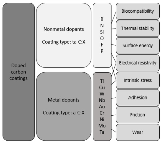
Figure 1.
Effect of dopants on the properties of doped carbon coating; modified from [11].

Table 1.
Effect of dopants and selected references.
Metal doping often results in a softening of the carbon matrix, shifting the bonding state from sp3 to sp2, leading to a-C:Me coatings [15,18]. Nonmetals or small amounts of carbide formers do not show such a sharp decline in hardness reduction compared to metal ones [1]. Thus, doped coatings (ta-C:X) with properties similar to ta-C are formed, for instance, with regard to high sp3/sp2 ratios. In many cases, a significant stress reduction is observed due to doping with metals or nonmetals [19].
Important for the comparison of the effects of the doping elements is the erosion behavior of cathodes during arc evaporation. The erosion behavior of pure cathodes is well analyzed [8,9,20,21,22,23,24,25,26,27,28,29], but a lack of information about compound cathodes still exists. Kimblin [25,26] and Daalder [21,22,23] show that the erosion rate Er, representing a mass loss per electric charge (µg/C), includes three main influences (see Equation (1)):
Er = Eion + EMP + Egas
The erosion rate is caused by ion evaporation (Eion), by macroparticles (EMP) and by gas formation (Egas), whereby the latter case plays a subordinate role.
The ion erosion rate Eion represents a lower limit for the erosion rate of a cathode material, and is only influenced by the arc current [23,30]. Daalder calculates this minimal erosion rate for pure carbon cathodes, where only ions contribute to the erosion with 13.16 µg/C [21,23]. For graphite composite cathodes, no information on erosion rates are available. For understanding the erosion behavior, it is not only the cathode material that is important; the size and structure of the cathode are also considered to be relevant [21,25,26].
In this study, the effect of doping was comprehensively investigated by using sintered composite cathodes made from graphite and doping element powders. Two nonmetals (B, Si) and two metals (Fe, Mo) were investigated as doping elements with the aim to tailor the coating properties in particular directions, as summarized in Table 1.
In recently published works, it was shown that doping with some elements can also reduce the surface roughness significantly, which is likely caused by a low emission of particles during evaporation [17] or due to smaller particles [42].
2. Materials and Methods
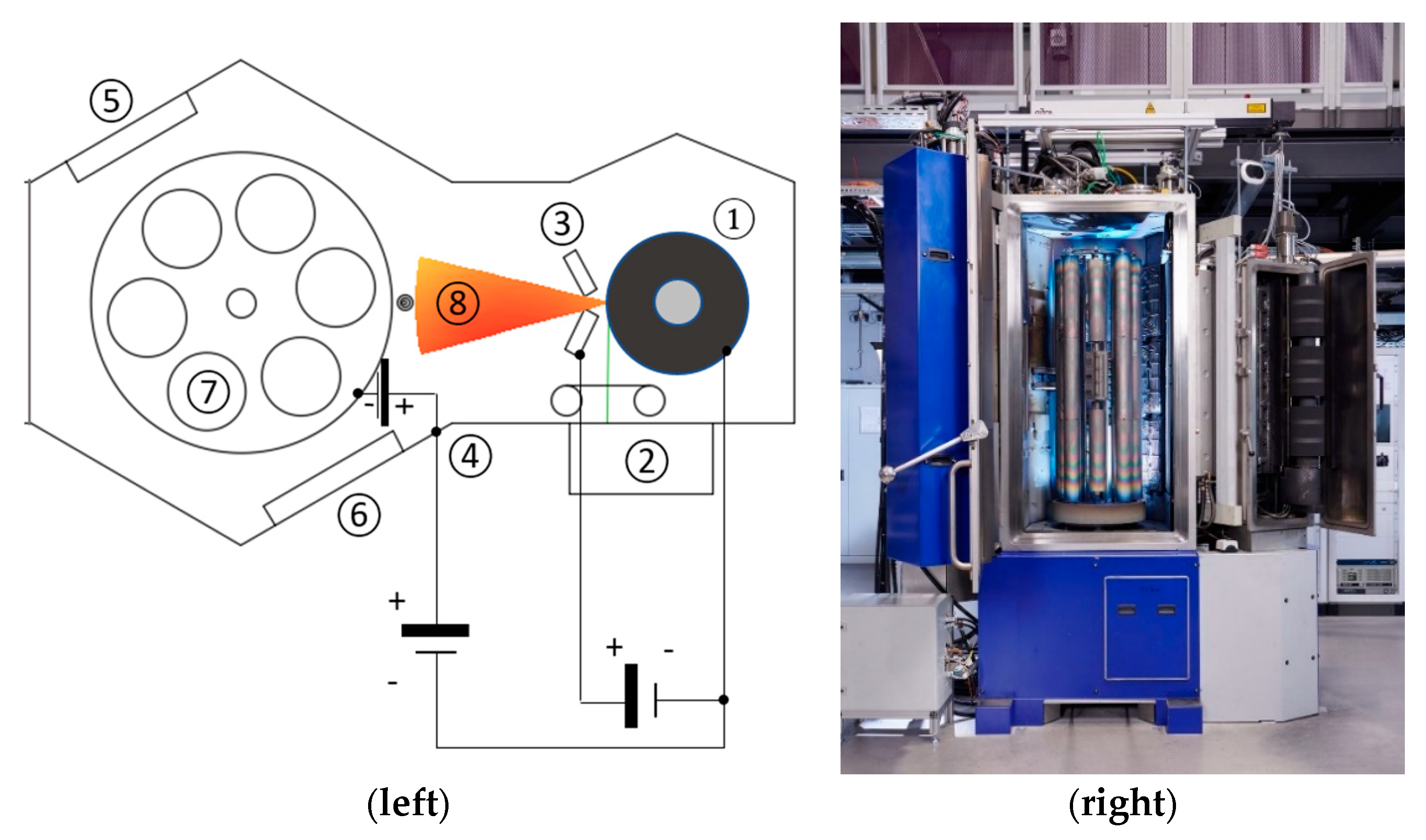
The experimental setup is shown in Figure 2. Evaporation was carried out in a high vacuum at a pressure of about 10−4 Pa. A pulsed vacuum arc discharge of the graphite cathode (Figure 2, (1)) produced the plasma (Figure 2, (8)), which mainly consists of positively charged carbon ions, electrons and, in the case of compound targets, also the positively charged ions of the doping element. Furthermore, neutrals and macroparticles were formed during the evaporation process. The repetitive ignition of the arc pulses was triggered by a pulsed laser using a commercial Q-switched, Nd-doped yttrium aluminum garnet (Nd-YAG) laser (Figure 2, (2)). The laser pulse length was about 100 ns, with an energy of about 15 mJ, which is smaller than the arc discharge energy by a factor of 1000 (approx. 15 J). The combination of the linear scanning of the laser spot and the rotation of the graphite target results in uniform erosion. The employed current source provides a sinusoidal current of up to 1600 A at a discharge duration of 330 μs. A pulsed bias voltage of 100 V was applied synchronously to the arc pulses. The duration of the bias pulse was set to 175 μs.
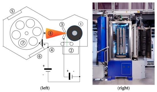
Figure 2.
Scheme of the coating device DREVA 1200 (left): (1) cathode; (2) laser scanning system; (3) two-part anode; (4) bias supply; (5) radiation heater; (6) magnetron sputtering source; (7) substrate holder and rotation; (8) plasma; and coating chamber with Laser-Arc ModuleTM LAM500 (right). Photo by ©Jürgen Jeibmann, Dresden, Germany.
Due to the reduced height of the modified graphite targets (180 mm in diameter at 60 mm height), and to allow low coating temperatures for these studies, the repetition rate was set to 50 Hz. The substrate ((7) in Figure 2) was set in a two-fold rotation and was equipped with a bias voltage source ((4) in Figure 2), which allowed defined bias pulse overlaps. A magnetron-sputtering source ((6) in Figure 2) was used to deposit a chromium interlayer to ensure the sufficient adhesion of the carbon coatings.
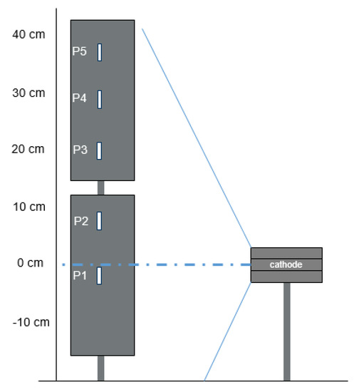
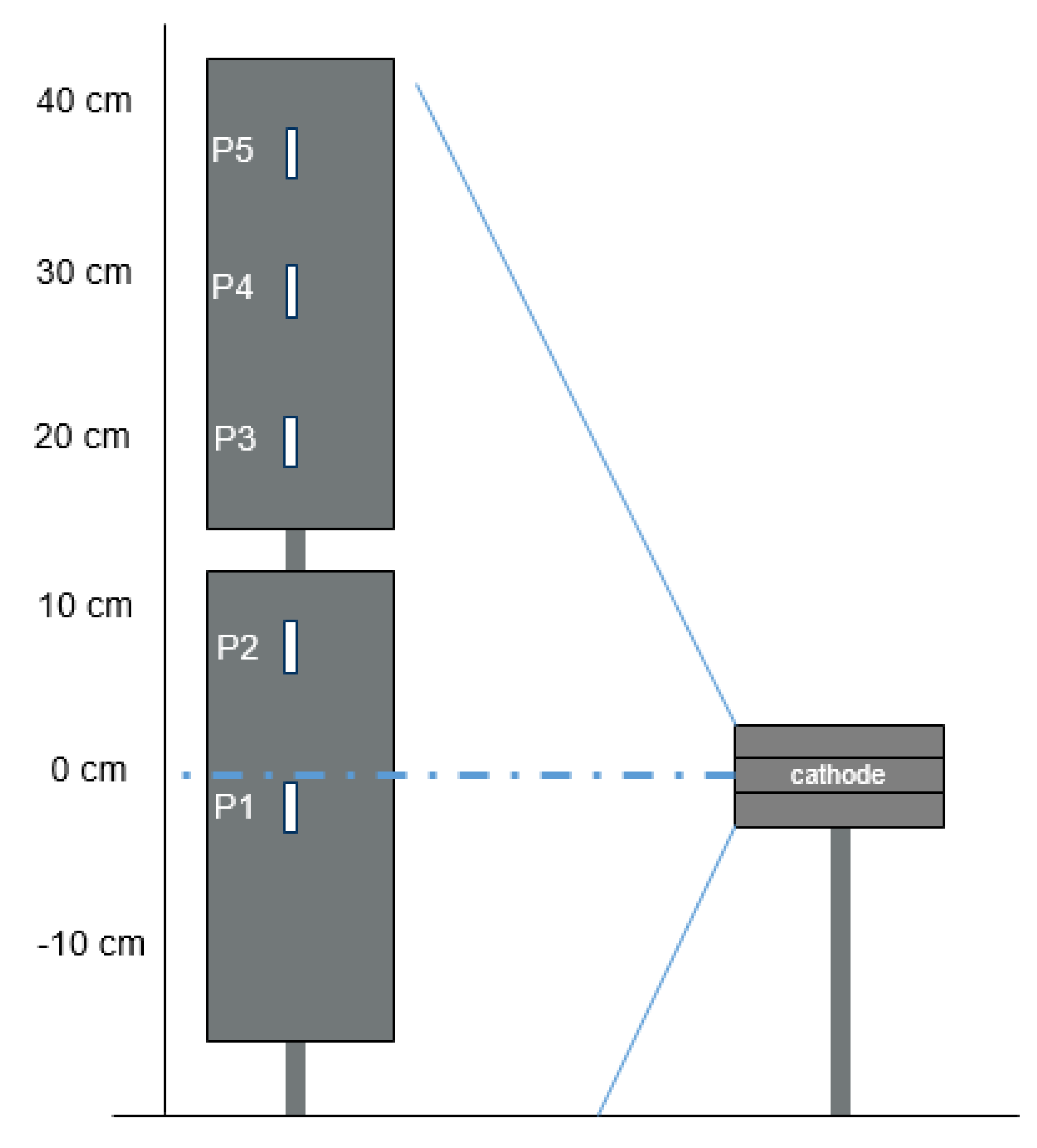
The main objective of this investigation was to study the evaporation process of modified and pure graphite cathodes and the properties of deposited doped and pure carbon coatings. For this purpose, pure graphite and sintered graphite compound cathodes with nominal amounts of 5 at.% B, Si, Fe or Mo were used to synthesize the ta-C and doped carbon coatings. In contrast to a standard cathode arrangement in the laser-arc process, with two graphite cylinders and a total cathode length of 40 cm, only small cylinder segments consisting of 3 discs each with a total height of 6 cm were used in this work. For the investigation of the chemical composition of the (t)a-C:X coatings as a function of height position in relation to the cathode position, several samples were mounted across the entire effective coating height (~60 cm) within the coating chamber (see Figure 3).
The coatings were deposited on flat steel samples (hardened low-alloy chromium steel (100Cr6, EN 1.3505, SAE 52100, Nosta GmbH, Höchstädt, Germany) with a size of 18 mm × 13 mm × 3 mm, polished to Ra < 20 nm). Prior to deposition, the samples were cleaned in an ultrasonic bath with an alkaline solution and then dried. For coating, they were fixed on a holder in an 8-axis planetary system and coated in a twofold rotation. The coating process started with an argon ion etching step using a hollow cathode. Next, a 100 nm thick Cr adhesion layer was deposited by magnetron sputtering, followed by (t)a-C:X deposition using an unfiltered laser-arc.
The evaporation process was characterized with respect to the lateral arc spot movement and erosion rates of the cathodes. The dimensions of the arc spot traces on the cathodes were measured after an evaporation of 1000 pulses. These values were averaged and put in relation to the respective evaporation current. By weighing (precision balance PCB 10000-1 Kern&Sohn GmbH, Balingen-Frommern, Germany) the cathodes prior and after the evaporation, the gravimetric erosion rate Er,g was calculated in relation to the electrical charge during the evaporation. The density of the cathodes was calculated from the initial weight and volume. With this information, the volumetric erosion rate Er,v could be derived. The deposition process and the prepared samples were characterized with respect to their deposition rate Dr and chemical composition. The deposition rate was calculated according to the coating thickness and effective deposition time from the number of ignited pulses and the pulse frequency. By means of the ball crater-grinding method (KSG110 from Inovap Dresden, now HEF Group, Andrézieux-Bouthéon, France), the coating thickness was measured according to DIN EN ISO 26423. For the analysis of the chemical composition, all samples were measured using SEM (acceleration voltage of 10 V, spot size 50 and working distance of 10–13 mm) with an EDS-system JEOL 6610 + X-Max 80 mm2 (JEOL, Akishima, Japan and X-MAX 80 from Oxford Instruments plc., Abingdon, United Kingdom). The chemical composition was determined using AZtec software (version: 3.3).
3. Results and Discussion
3.1. Coating Properties and Deposition Rate
A summary of selected coating properties from sample position P1 (Figure 3) is given in Table 2. Additional information about the coating properties can be found elsewhere [42]. All coatings were prepared with a similar coating thickness. Coatings containing nonmetal dopants have mechanical properties and deposition rates comparable with undoped ta-C, whereby a slight reduction with dopant amounts of around 5 at.% could be observed. In the case of metal dopants, hardness and Young’s modulus and the deposition rates were drastically reduced, with a simultaneously higher doping content in the coating. The highest deposition rate is obtained for undoped ta-C, while the lowest deposition rate is observed for a-C:Fe, with the highest amount of dopant in the coating.
Table 2.
Properties of ta-C and (t)a-C:X coatings, mounted on sample position P1; summary from [42].
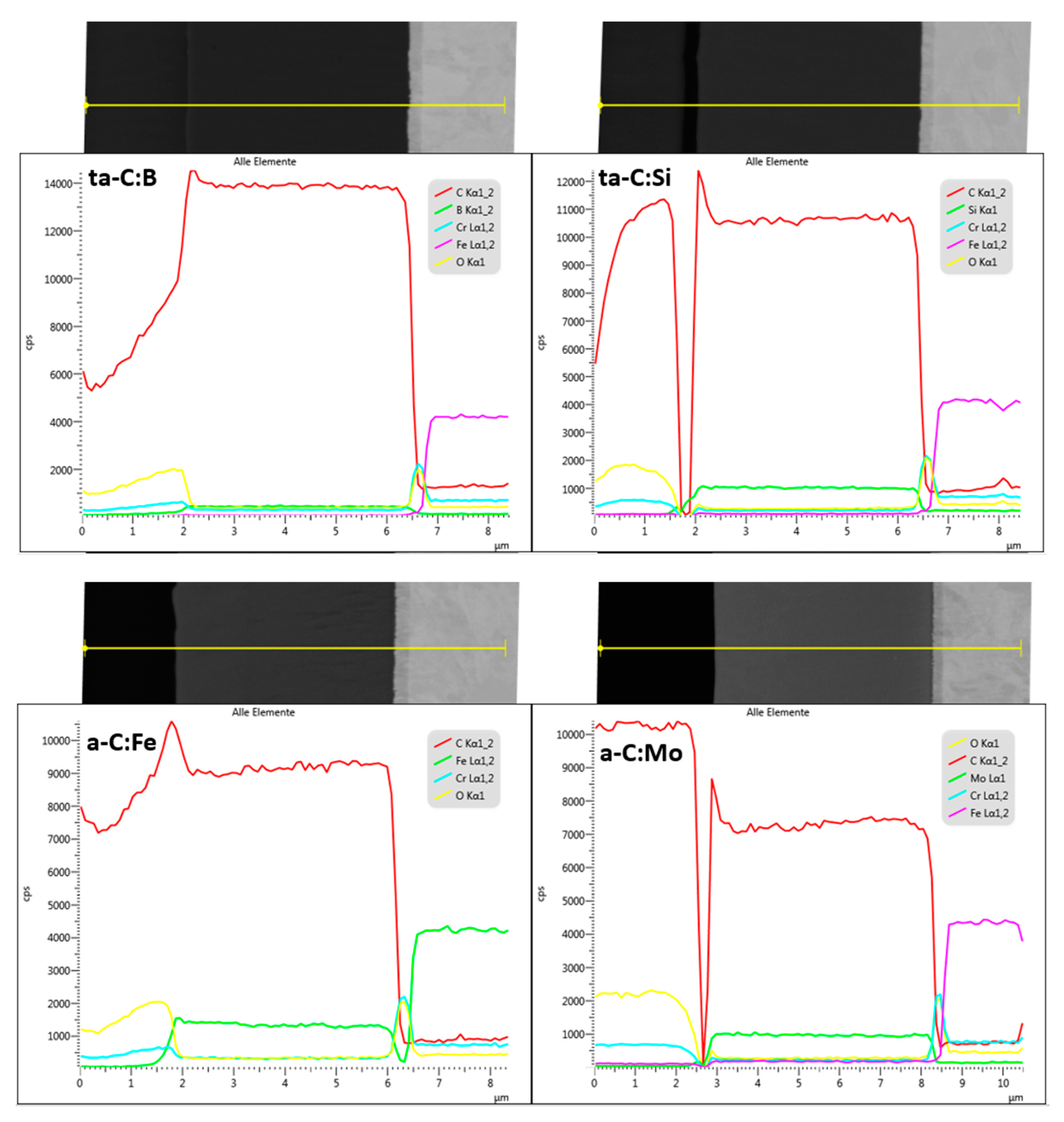
The elemental distribution within the doped coatings was analyzed by cross-section EDS analysis in SEM (Figure 4). Fe-containing coatings show a very slight increase in Fe from the interface to the surface of the coating, whereas the other coatings show no significant gradient over the coating thickness. Therefore, no evidence for macroscopic variations in composition or temporal effects on deposition can be detected. The significant drop in the measured signal for ta-C:Si and a-C:Mo is an artefact of the metallographic preparation. Here, a narrow gap has formed between the sample and the embedding medium, which led to the observed drop.
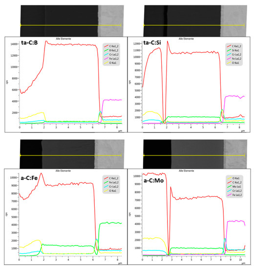
Figure 4.
EDS line scan measurements with the signals of the identified elements (see colored lines) on cross-sections of doped carbon coatings. In the SEM pictures, the indexed position of the line scan is shown (yellow lines; scale bar of SEM pictures corresponds to the X-axis).
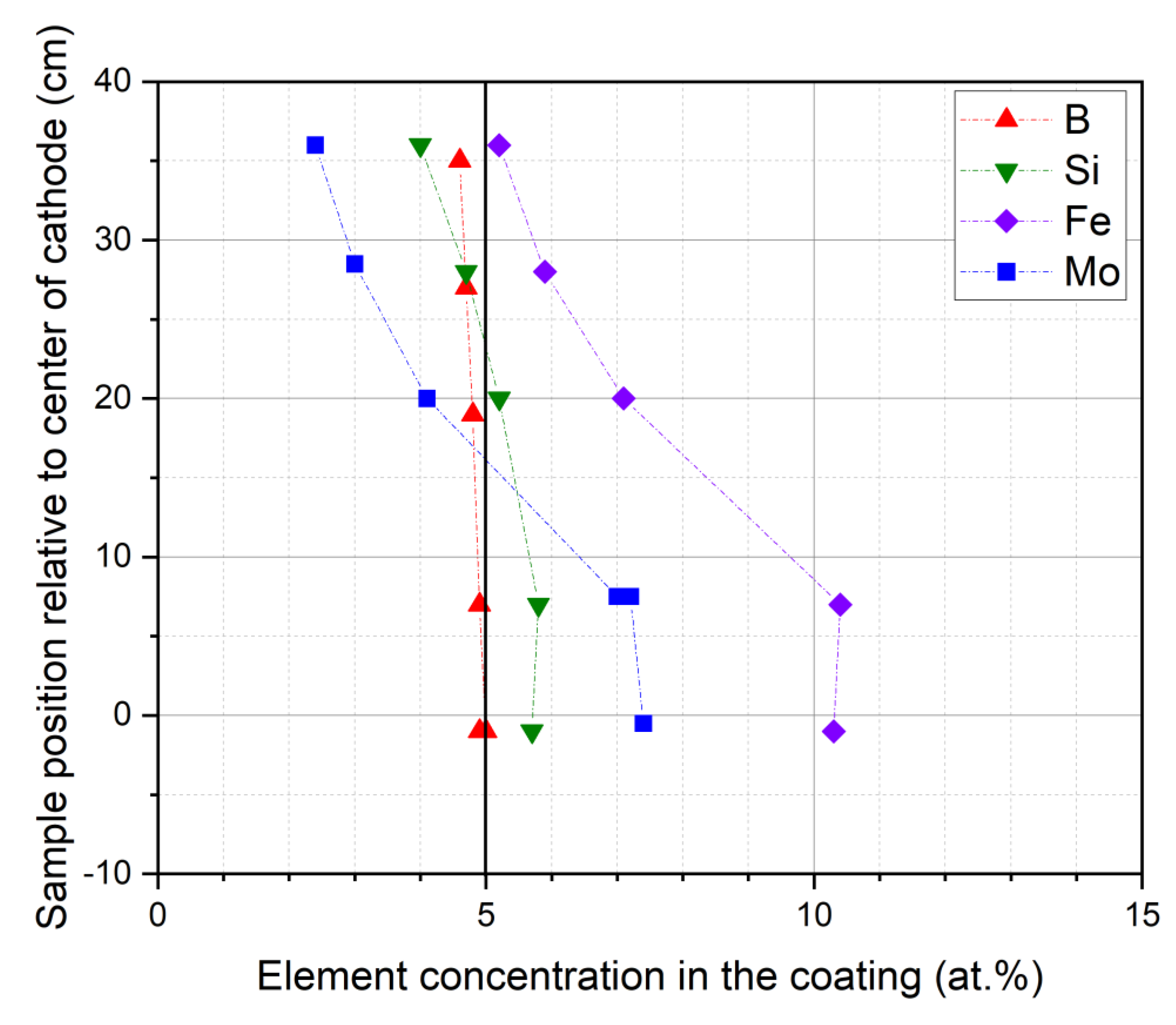
For every sample position in relation to the cathode (see Figure 3), the chemical composition of the coatings was evaluated. The results of the position-dependent compositions for all doped coatings are shown in Figure 5. From the plasma investigations [1], it is known that the emission of species into the vacuum chamber shows an angular distribution. Due to this angular distribution, an elemental distribution of dopants in the deposited coatings may occur. Furthermore, the varying absolute and horizontal distance (see Figure 3) between the cathode and the position of each sample relative to the plane of the cathode could result in a variation in the amount of dopant in the coating. In the case of ta-C:B, the coating composition shows almost no deviation in the chemical composition in relation to the sample position, and the content of B corresponds to the nominal amount of B in the cathode material. In the case of Si, a slight deviation in the coating composition from the nominal Si amount in the cathode and in its dependence on the sample position is observed. Along the plane of the cathode’s center, the amount of Si is around 6 at.%; with increasing distance, the amount of Si decreases down to 4 at.%.
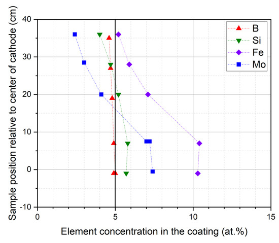
Figure 5.
Element concentration over the vertical sample position relative to the center of the cathode; the nominal element concentration in the cathode is 5 at.%.
In the case of metals as doping elements, a more pronounced distribution in the chemical composition in relation to the sample position occurs, especially for Fe. On the sample along the plane at the cathode’s center, the Fe content reaches a maximum of around 10 at.%, which is twice as high as the nominal amount of Fe in the cathode. Chen et al. [15] find a similar behavior of Fe enrichment in coatings caused by several effects. A preferential evaporation of Fe, due to the differences in the melting temperature of Fe and C, could be an explanation. By increasing the distance to the plane of the cathode center, a continuous decrease in Fe content down to around 5 at.% is clearly visible. A similar behavior is obtained by doping with Mo. The sample position along the plane at the cathode center leads to a slightly higher amount of Mo compared with the nominal cathode composition, but towards the outer positions, a decrease in the amount of Mo is recognizable. The reduction in hardness and Young’s modulus in the metal-doped coatings (see Table 2 and [42]) is attributed to the effect on the formation of sp3-bonded C-bonds. Thus, it can be assumed that the relatively heavy metal atoms hinder the formation of three-dimensional sp3 structures and, thus, favor the formation of the (planar) sp2 structures.
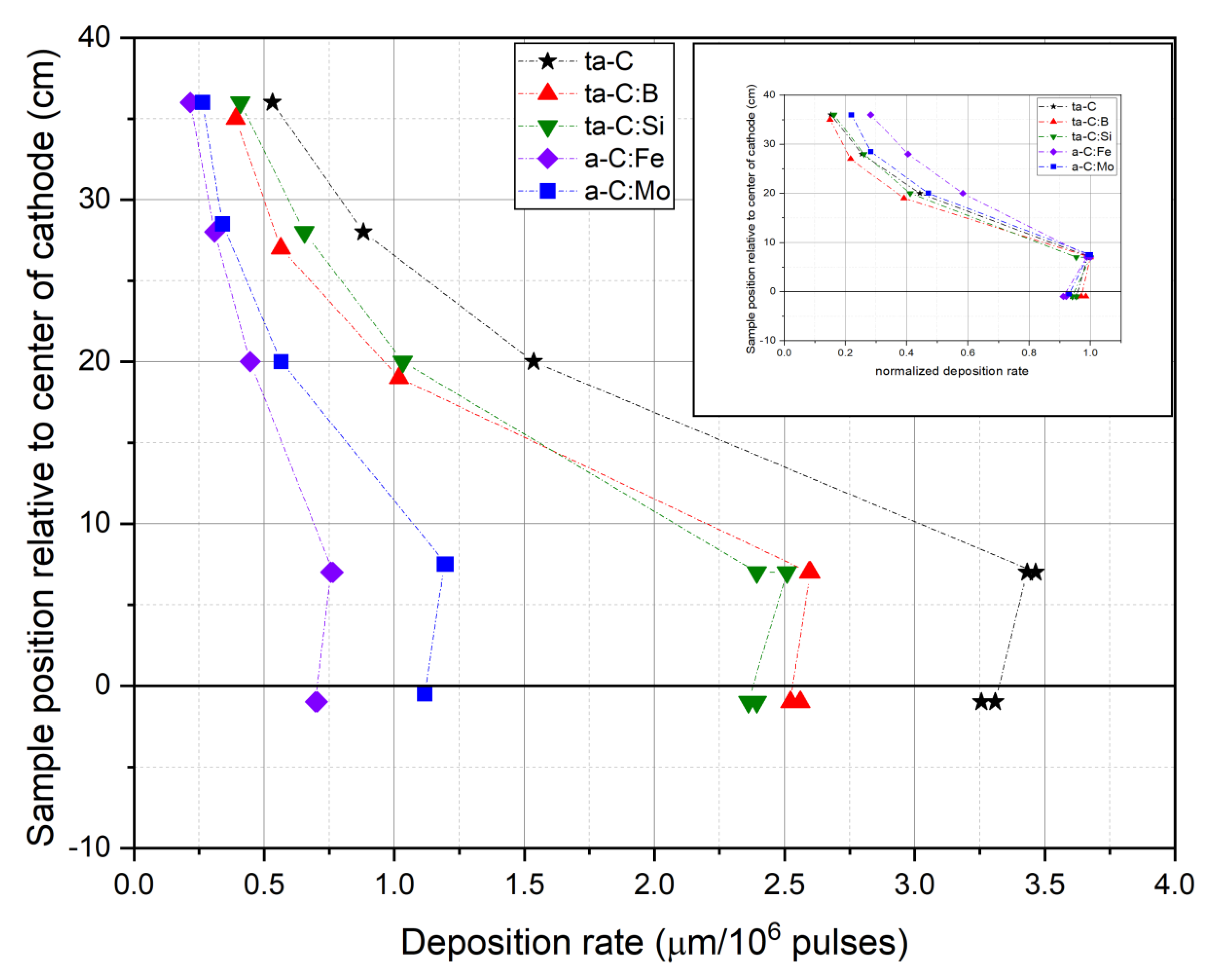
Finally, investigations were carried out on the deposition rate as a function of the vertical sample position. First, it should be clarified whether the deposition rate for the distribution of the doped coatings differs from pure ta-C. For comparison, the absolute and the normalized (to the highest value of each distribution) deposition rate is shown in Figure 6. In general, the deposition rate decreases towards the sample positions away from the plane of the cathode center. It should be mentioned that the plasma focus is slightly shifted upwards, also causing a shift in the deposition rate and the chemical content. Undoped ta-C has the highest absolute deposition rates for all the sample positions. B and Si doping leads to a significant reduction in the deposition rate by about 25%. However, a drastic reduction occurs in the case of Mo and Fe dopants: here, the deposition rate is reduced by about 65% (Mo) and about 80% (Fe) at the maximum.
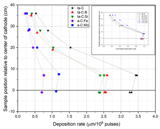
Figure 6.
Absolute and normalized (inlay) deposition rates of different sample positions relative to the cathode center.
Three possible reasons for the differences in deposition rates are: (a) the evaporation or erosion rates, (b) the possible shadowing of the plasma at the anode slot due to arc spots of different sizes or (c) a different distribution of the plasma in the coating chamber. The latter reason obviously plays a subordinate role, as the normalized representation of the distributions (see inlay in Figure 6) shows a somewhat broader distribution only for the case of Fe doping.
In the next section, the influence of the erosion rate (a) and the trace of the arc spot (b) on the deposition rate will be investigated.
3.2. Cathode Erosion and Arc Spots
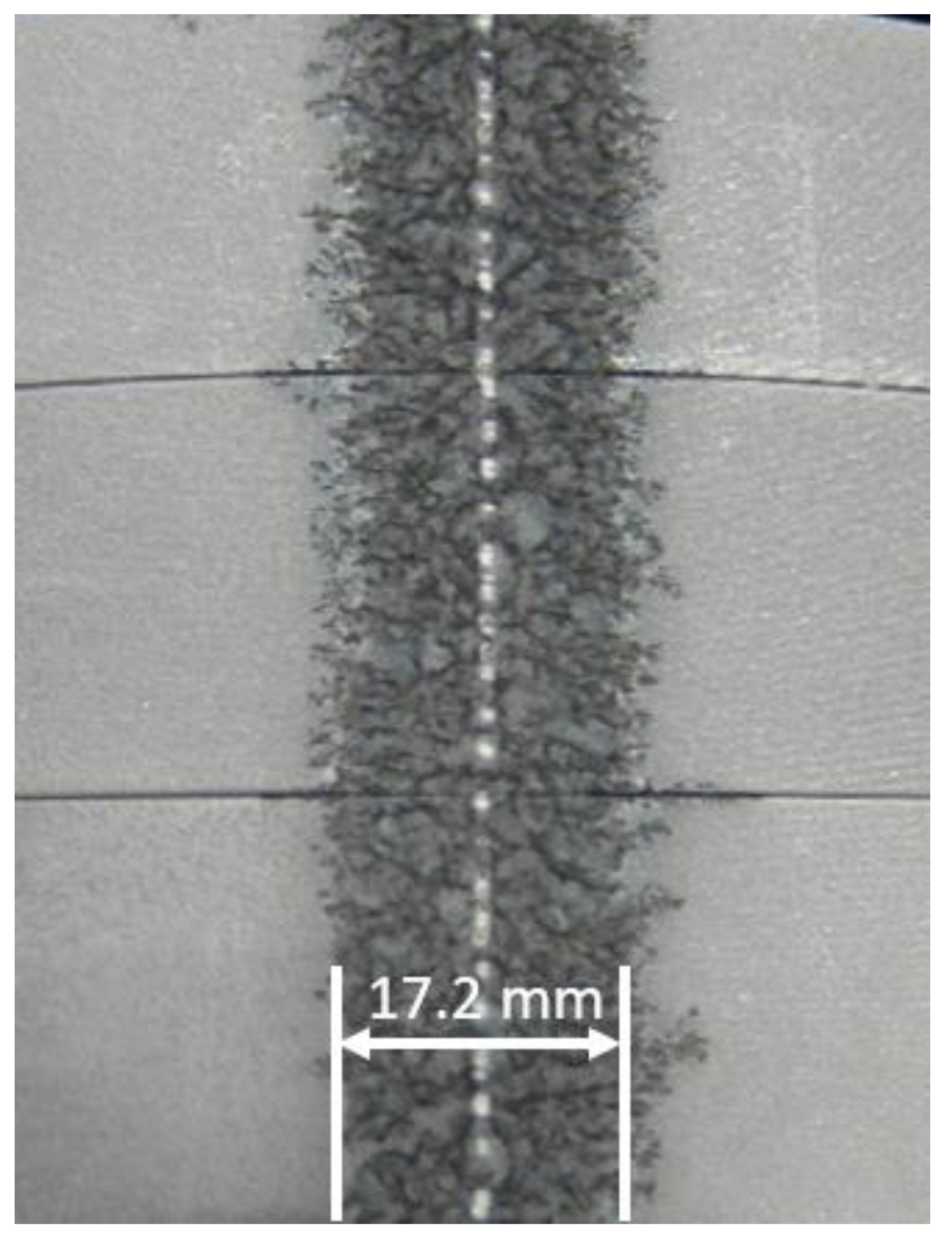
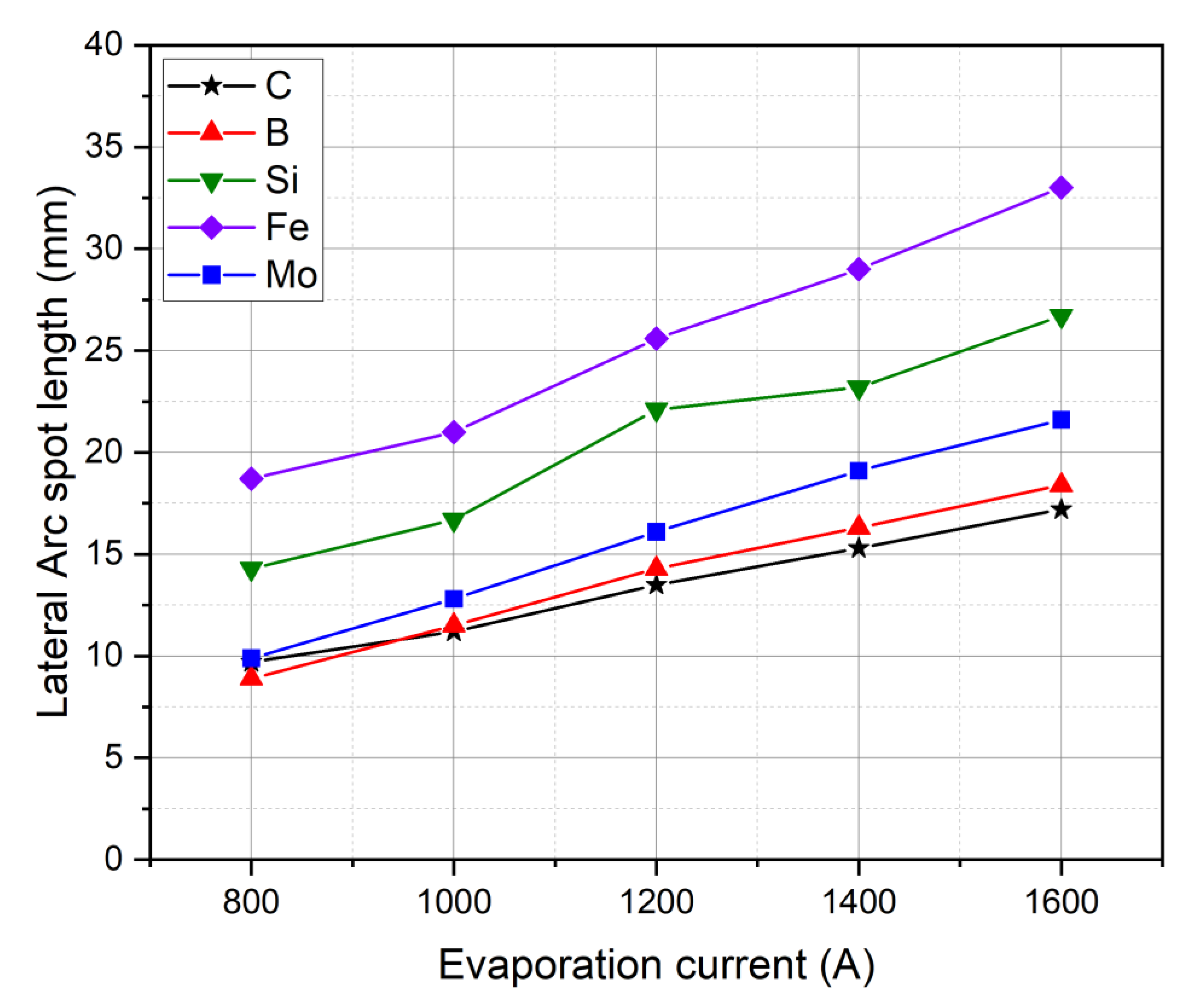
In order to understand the influence of doping elements on the deposition rates, investigations were carried out on the erosion of the cathodes during arc evaporation, as well as on the expansion of the arc spots on the cathode surface (Figure 7). For all cathodes, the lateral size of the traces of arc spots in relation to the evaporation current is shown in Figure 8. Generally, by increasing the arc evaporation current from 800 to 1600 A, the arc spots tend to spread in a more pronounced manner over the cathode surface, leading to an increase in the arc spot movement size. For B-modified and pure graphite cathodes, the arc spot movement is low, whereas the arc spots on Fe- and Si-modified graphite cathodes show a pronounced further spread of the arcs. The measurements may suggest that the expansion of the arc spots scales indirectly and proportionally to the cohesive energy of the cathode material. Values for the cohesive energy of the graphite and elements added to the graphite cathode are listed in Table 3. Additionally, an influence of the electrical conductivity or microstructure (e.g., porosity) of the cathode material on the movement of arc spot on the cathode surface was discussed for different types of graphite by Kandah et al. [6,8,9].
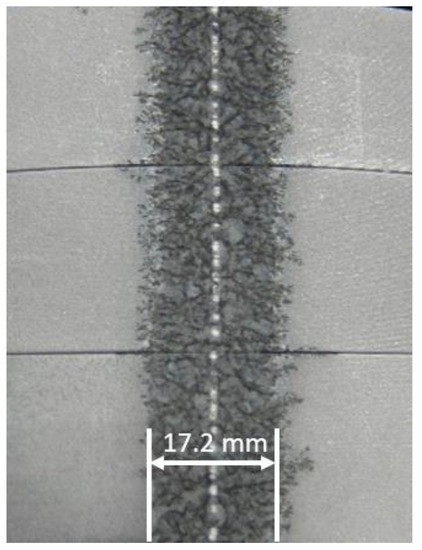
Figure 7.
Example of traces of arc spots on graphite cathode surface with an arc current of 1600 A. The calculated lateral arc spot movement length is 17.2 mm.
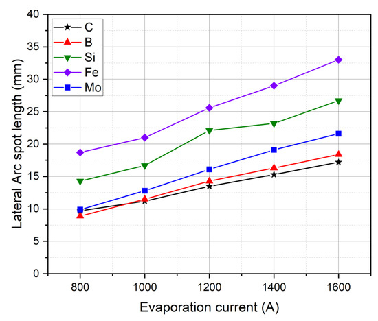
Figure 8.
Lateral size of arc spot traces on the cathode surface in relation to the evaporation current.
Table 3.
Atomic mass and cohesive energy of carbon and doping materials.
In Table 4, the calculated erosion rates of graphite and modified graphite cathodes are shown. For pure carbon cathodes, the highest erosion rate is observed. By modifying the graphite cathode, the erosion rate for all types is reduced. The reduction in the erosion rate for Mo- and Fe-modified cathodes is more pronounced than for B- and Si-modified ones.
Table 4.
Comparison of gravimetric and volumetric erosion rate and calculated density of target material for an evaporation current I = 1600 A.
As described above (Equation (1)), the erosion rate consists predominantly of an ion erosion rate Eion and a macroparticle erosion rate EMP. The ion erosion rates known from the literature are about 13 µg/C for graphite [21,23], 40–50 µg/C for metallic Fe [23] and 50–55 µg/C for metallic Mo [23] (no data are available for pure B and Si because these materials are not evaporable in the arc process). Surprisingly, adding Fe or Mo to the graphite does not increase the erosion rate, but decreases it drastically, as can be seen in Table 4. This cannot have anything to do with the macroparticle emission rate EMP, because the Fe- and Mo-doped coatings tend to show even fewer particle-induced defects than in the case of pure ta-C [42]. The drastic reduction in the erosion rate of composite cathodes compared to pure graphite must therefore have other reasons. We suspect that this is related to the local electrical conductivity in the composite graphite, which influences the formation of current paths in the cathode. Even in pure graphite, Kandah [6] has found strong differences in erosion rates depending on the graphite type, i.e., the structure of the graphite cathode.
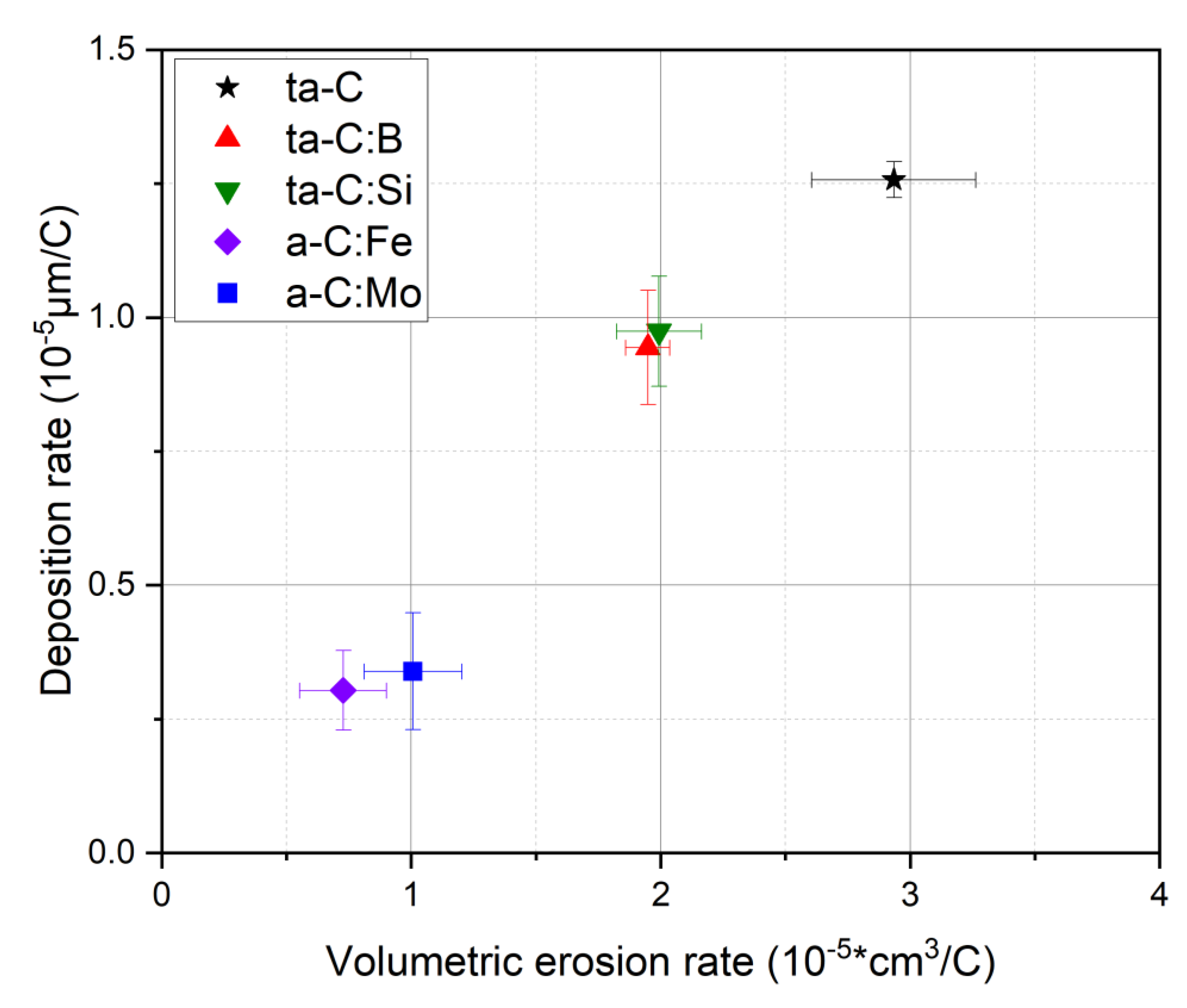
A higher erosion rate Er,v results in a higher deposition rate Dr. This almost linear relationship is illustrated in Figure 9. A pure carbon cathode with the highest erosion rate of around Er,v = 2.9 × 10⁻⁵ cm3/C exhibits also the highest deposition rate Dr = 1.3 µm/C compared to the modified cathodes. Corresponding to the reduction of the erosion rate, the deposition rate is also moderately reduced in the case of nonmetals (B, Si), and drastically so in the case of metals (Fe and Mo).
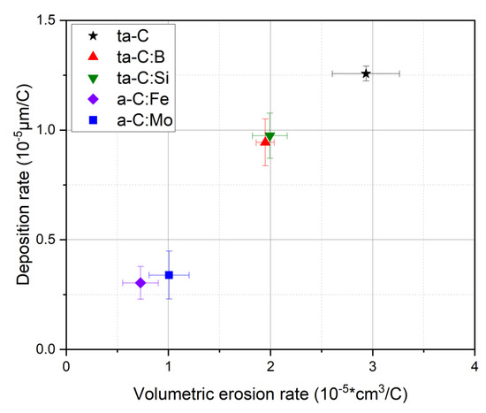
Figure 9.
Deposition rate Dr over the volumetric erosion rate Er,v of coatings for sample position P1; mounted along the plane of the cathode center.
The linear relationship makes it clear that the erosion rate is the primary cause of the differences in deposition rates. All other influences, such as the shading of the plasma as it passes through the anode shield or different plasma distributions in the chamber, are secondary in their effects.
4. Conclusions
In this paper, pure ta-C and doped carbon coatings with metal and nonmetal elements were deposited using a laser-arc evaporation process. Both the influence of the added elements on the cathode erosion and the influence on the deposited (t)a-C:X coating properties were investigated. It was shown that doped (t)a-C:X coatings with homogeneous element distribution can be reliably produced with the laser-arc process. By analyzing the homogeneity by means of EDS measurements, no evidence of chemical gradient or temporal effects of the chemical deposition was observed. Investigations into the deposition rate and the chemical composition in relation to the vertical sample position revealed a similar deposition behavior with respect to the deposition rate distribution. Slight deviations in the chemical content of the coatings, differing with the sample position, were found for nonmetals, whereas metal doping led to a strong deviation in the chemical content of the coating. The deposition rates for the doped coatings are lower than for pure ta-C. A drastic reduction was observed in the case of the metal dopants (Fe and Mo). It was shown that the greatest influence of the deposition rate lies in the erosion rate during arc discharge on the cathode. However, minor influencing factors can also be the height distribution of the plasma as well as the lateral expansion of the arc spots, in combination with the shadowing effect of the anode shield.
Further investigations should be conducted using TEM and Raman analysis to clarify the coating structure, how dopants are incorporated in the carbon coatings and how they change the properties of coatings in detail. Furthermore, the extent to which the doped coatings can be deposited on parts with more complex geometry, and whether there are geometric influencing factors, should also be investigated. A final important object of investigation would be to find the cause of the strong differences in erosion rates for the different dopants in the cathodes, and the extent to which this has something to do with the emission of macroparticles.
Author Contributions
Conceptualization, T.K., F.K. (Florian Kirsten) and V.W.; methodology, T.K. and F.K. (Frank Kaulfuß); validation, T.K., F.K. (Florian Kirsten) and F.K. (Frank Kaulfuß); formal analysis, T.K. and F.K. (Florian Kirsten); investigation, F.H. and F.K. (Florian Kirsten); resources, F.H.; data curation, T.K., F.K. (Frank Kaulfuß) and F.K. (Florian Kirsten); writing—original draft preparation, T.K.; writing—review and editing, T.K., F.K. (Frank Kaulfuß) and V.W.; supervision, V.W.; project administration, F.K. (Frank Kaulfuß) and V.W. All authors have read and agreed to the published version of the manuscript.
Funding
This research was funded by the German Federal Ministry of Economic Affairs and Energy (BMWi), grant numbers 03ET1609 E.
Institutional Review Board Statement
Not applicable.
Informed Consent Statement
Not applicable.
Data Availability Statement
Data available on request due to restrictions/data sharing not applicable.
Acknowledgments
The authors would like to thank the colleagues and students of the Department of Carbon Coatings at Fraunhofer IWS and Jörg Kaspar and Martin Kuczyk from the Group of Materials and Failure Analysis.
Conflicts of Interest
The authors declare no conflict of interest. The funders had no role in the design of the study; in the collection, analyses, or interpretation of data; in the writing of the manuscript, or in the decision to publish the results.
References
- Anders, A. Cathodic Arcs: From Fractal Spots to Energetic Condensation; Springer: New York, NY, USA, 2008; ISBN 9780387791074. [Google Scholar]
- Schultrich, B. Tetrahedrally Bonded Amorphous Carbon Films I: Basics, Structure and Preparation; Springer: Berlin, Germany, 2018; ISBN 978-3-662-55925-3. [Google Scholar]
- Bewilogua, K.; Hofmann, D. History of diamond-like carbon films—From first experiments to worldwide applications. Surf. Coat. Technol. 2014, 242, 214–225. [Google Scholar] [CrossRef]
- Kaulfuss, F.; Weihnacht, V.; Zawischa, M.; Lorenz, L.; Makowski, S.; Hofmann, F.; Leson, A. Effect of Energy and Temperature on Tetrahedral Amorphous Carbon Coatings Deposited by Filtered Laser-Arc. Materials 2021, 14, 2176. [Google Scholar] [CrossRef] [PubMed]
- Vetter, J. 60 years of DLC coatings: Historical highlights and technical review of cathodic arc processes to synthesize various DLC types, and their evolution for industrial applications. Surf. Coat. Technol. 2014, 257, 213–240. [Google Scholar] [CrossRef]
- Kandah, M.; Meunier, J.-L. Vacuum arc cathode spot movement on various kinds of graphite cathodes. Plasma Sources Sci. Technol. 1996, 5, 349–355. [Google Scholar] [CrossRef]
- Fraunhofer-Gesellschaft zur Föderung der angewandten Forschung e.V. Offenlegungsschrift. Verfahren zur Bearbeitung von Oberflächen einer Beschichtung aus Hartem Kohlenstoff. Patent DE102006010916A1, 1 March 2006.
- Kandah, M.; Meunier, J.-L. Study of microdroplet generation from vacuum arcs on graphite cathodes. J. Vac. Sci. Technol. A 1995, 13, 2444–2450. [Google Scholar] [CrossRef]
- Kandah, M.; Meunier, J.-L. Erosion Study on Graphite Cathodes Using Pulsed Vacuum Arcs. IEEE Trans. Plasma Sci. 1996, 24, 523–527. [Google Scholar] [CrossRef]
- Donnet, C.; Erdemir, A. (Eds.) Tribology of Diamond-Like Carbon Films: Fundamentals and Applications; Springer: Berlin, Germany, 2008; Available online: https://link.springer.com/book/10.1007/978-0-387-49891-1 (accessed on 5 January 2022).
- Sánchez-López, J.C.; Fernández, A. Doping and Alloying Effects on DLC Coatings. In Tribology of Diamond-Like Carbon Films: Fundamentals and Applications; Donnet, C., Erdemir, A., Eds.; Springer: Berlin, Germany, 2008; pp. 311–338. [Google Scholar]
- Zia, A.W.; Zhou, Z.; Li, L.K.-Y. Structural mechanical and tribological characteristics of DLC coatings: Chapter 7. In Nanomaterials-Based Coatings: Fundamentals and Applications; Nguyen Tri, P., Rtimi, S., Ouellet Plamondon, C.M., Eds.; Elsevier: Amsterdam, The Netherlands, 2019; pp. 171–194. ISBN 978-0-12-815884-5. [Google Scholar]
- Zhang, C.; Liu, Y.; Yang, Z.; Chen, L.; Qiao, S. Cathode spot movement on a continuous carbon fiber reinforced Cu matrix composite in vacuum. Vacuum 2013, 93, 45–49. [Google Scholar] [CrossRef]
- Polster, M. Abscheidung von dotierten Kohlenstoffschichten mit dem laserinduzierten Vakuumbogen. Ph.D. Thesis, Westsächsiche Hochschule Zwickau, Zwickau, Germany, 2002. [Google Scholar]
- Chen, J.S.; Lau, S.P.; Chen, G.Y.; Sun, Z.; Li, Y.J.; Tay, B.K.; Chai, J.W. Deposition of iron containing amorphous carbon films by filtered cathodic vacuum arc technique. Diam. Relat. Mater. 2001, 10, 2018–2023. [Google Scholar] [CrossRef]
- Jang, Y.-J.; Kang, Y.-J.; Kitazume, K.; Umehara, N.; Kim, J. Mechanical and electrical properties of micron-thick nitrogen-doped tetrahedral amorphous carbon coatings. Diam. Relat. Mater. 2016, 69, 121–126. [Google Scholar] [CrossRef]
- Kim, J.-I.; Jang, Y.-J.; Kim, J.; Kim, J. Effects of silicon doping on low-friction and high-hardness diamond-like carbon coating via filtered cathodic vacuum arc deposition. Sci. Rep. 2021, 11, 3529. [Google Scholar] [CrossRef]
- Pasaja, N.; Sansongsiri, S.; Intarasiri, S.; Vilaithong, T.; Anders, A. Mo-containing ta-C deposited by dual filtered cathodic vacuum arc with selective pulsed bias voltage. Nuclear Instr. Methods Phys. Res. 2007, B259, 867–870. [Google Scholar] [CrossRef] [Green Version]
- Chhowalla, M.; Yin, Y.; Amaratunga, G.A.J.; McKenzie, D.R.; Frauenheim, T. Highly tetrahedral amorphous carbon films with low stress. Appl. Phys. Lett. 1996, 69, 2344–2346. [Google Scholar] [CrossRef]
- Anders, S.; Anders, A.; Yu, K.M.; Yao, X.Y.; Brown, I.G. On the macroparticle flux from vacuum arc cathode spots. IEEE Trans. Plasma Sci. 1993, 21, 440–446. [Google Scholar] [CrossRef]
- Daalder, J.E. Erosion and the origin of charged and neutral species in vacuum arcs. J. Phys. D 1975, 8, 1647. [Google Scholar] [CrossRef]
- Daalder, J.E. Components of cathode erosion in vacuum arcs. J. Phys. D 1976, 9, 2379–2397. [Google Scholar] [CrossRef]
- Daalder, J.E. Cathode Spots and Vacuum Arcs. Physica C 1981, 104, 91–106. [Google Scholar] [CrossRef]
- Davis, W.D.; Miller, H.C. Analysis of the Electrode Products Emitted by dc Arcs in a Vacuum Ambient. J. Appl. Phys. 1969, 40, 2212–2221. [Google Scholar] [CrossRef]
- Kimblin, C.W. Erosion and ionization in the cathode spot regions of vacuum arcs. J. Appl. Phys. 1973, 44, 3074–3081. [Google Scholar] [CrossRef]
- Kimblin, C.W. Cathode spot erosion and ionization phenomena in the transition from vacuum to atmospheric pressure arcs. J. Appl. Phys. 1974, 45, 5235–5244. [Google Scholar] [CrossRef]
- Koch, A.W.; Nürnberg, A.W.; Behrisch, R. Investigation of Vacuum Arcs on Graphite Cathodes. J. Nucl. Mat. 1984, 122–123, 1437–1439. [Google Scholar] [CrossRef]
- Sethuraman, S.K.; Chatterton, P.A.; Barrault, M.R. A Study of the Erosion Rate of Vacuum Arcs in a transverse Magnetic Field. J. Nucl. Mat. 1982, 111–112, 510–516. [Google Scholar] [CrossRef]
- Chhowalla, M.; Weiler, M.; Davis, C.A.; Kleinsorge, B.; Amaratunga, G.A.J. Deposition of smooth tetrahedral amorphous carbon thin films using a cathodic arc without a macroparticle filter. Appl. Phys. Lett. 1995, 67, 894–896. [Google Scholar] [CrossRef]
- Anders, A.; Oks, E.M.; Yushkov, G.Y.; Savkin, K.P.; Brown, Y.; Nikolaev, A.G. Determination of the specific ion erosion of the vacuum arc cathode by measuring the total ion current from the discharge plasma. Tech. Phys. 2006, 51, 1311–1315. [Google Scholar] [CrossRef]
- Chhowalla, M.; Yin, Y.; Amaratunga, G.A.J.; McKenzie, D.R.; Frauenheim, T. Boronated tetrahedral amorphous carbon (ta-C:B). Diam. Relat. Mater. 1997, 6, 207–211. [Google Scholar] [CrossRef]
- Kautek, W.; Pentzien, S.; Conradi, A.; Krüger, J.; Brzezinka, K.-W. Pulsed-laser deposition and boron-blending of diamond-like carbon (DLC)thin films. Appl. Surface Sci. 1996, 106, 158–165. [Google Scholar] [CrossRef]
- Kleinsorge, B.; Ilie, A.; Chhowalla, M.; Fukarek, W.; Milnne, W.I.; Robertson, J. Electrical and optical properties of boronated tetrahedrally bonded amorphous carbon (ta-C:B). Diam. Relat. Mater. 1998, 7, 472–476. [Google Scholar] [CrossRef]
- Krauser, J.; Nix, A.-K.; Gehrke, H.-G.; Hofsäss, H.; Trautmann, C.; Weidinger, A. Conductivity enhancement of ion tracks in tetrahedral amorphous carbon by doping with N, B, Cu and Fe. Nucl. Instr. Methods Phys. Res. 2012, B272, 280–283. [Google Scholar] [CrossRef]
- Panwar, O.S.; Khan, M.A.; Satyanarayana, B.S.; Kumar, S. Properties of boron and phosphorous incorporated tetrahedral amorphous carbon films grown using filtered cathodic vacuum arc process. Appl. Surf. Sci. 2010, 256, 4383–4390. [Google Scholar] [CrossRef]
- Ghadai, R.K.; Das, S.; Kumar, D.; Mondal, S.C.; Swain, B.P. Correlation between structural and mechanical properties of silicon doped DLC thin films. Diam. Relat. Mater. 2018, 82, 25–32. [Google Scholar] [CrossRef]
- Hilbert, J. Understanding and Improving The Environmental Dependent Tribology and Thermal Stability of Hydrogenated Amorphous Carbon by Using Silicon and Oxygen as Dopants. Ph.D. Thesis, University of Pennsylvania, Pennsylvania, PA, USA, 2018. [Google Scholar]
- Chen, J.S.; Lau, S.P.; Sun, Z.; Chen, G.Y.; Li, Y.J.; Tay, B.K.; Chai, J.W. Metal-containing amorphous carbon films for hydrophobic application. Thin Solid Films 2001, 398, 110–115. [Google Scholar] [CrossRef]
- Li, X.; Zhang, D.; Lee, K.-R.; Wang, A. Effect of metal doping on structural characteristics of amorphous carbon system: A first-principles study. Thin Solid Films 2016, 607, 67–72. [Google Scholar] [CrossRef]
- Ray, S.C.; Pong, W.F.; Papakonstantinou, P. Iron, nitrogen and silicon doped diamond like carbon (DLC) thin films: A comparative study. Thin Solid Films 2016, 610, 42–47. [Google Scholar] [CrossRef]
- Wang, L.L.; Wang, R.Y.; Yan, S.J.; Zhang, R.; Yang, B.; Zhang, Z.D.; Huang, Z.H.; Fu, D.J. Structure and properties of Mo-containing diamond-like carbon films produced by ion source assisted cathodic arc ion-plating. Appl. Surf. Sci. 2013, 286, 109–114. [Google Scholar] [CrossRef]
- Krülle, T.; Peritsch, P.; Kaulfuß, F.; Bui Thi, Y.; Zawischa, M.; Weihnacht, V. Investigation of surface defects on doped and undoped carbon coatings deposited by Laser Arc Technology using an optical surface quantification method. In Jahrbuch Oberflächentechnik 2021; Sörgel, T., Ed.; Eugen G. Leuze Verlag KG: Bad Saulgau, Germany, 2022. [Google Scholar]
- Widany, J. Density-Functional Tight-Bindung Calculations on the Straucture of Complex Boron Nitride Systems. Ph.D. Thesis, TU Chemnitz, Chemnitz, Germany, 1997. [Google Scholar]
Publisher’s Note: MDPI stays neutral with regard to jurisdictional claims in published maps and institutional affiliations. |
© 2022 by the authors. Licensee MDPI, Basel, Switzerland. This article is an open access article distributed under the terms and conditions of the Creative Commons Attribution (CC BY) license (https://creativecommons.org/licenses/by/4.0/).