Article

Jointing of CFRP/5083 Aluminum Alloy by Induction Brazing: Processing, Connecting Mechanism, and Fatigue Performance

Key Laboratory of Advanced Technologies of Materials, Ministry of Education, School of Materials Science and Engineering, Southwest Jiaotong University, Chengdu 610031, China
*
Author to whom correspondence should be addressed.
Coatings 2022, 12(10), 1559; https://doi.org/10.3390/coatings12101559
Submission received: 26 September 2022 / Revised: 10 October 2022 / Accepted: 13 October 2022 / Published: 16 October 2022

Abstract

:
Carbon fiber reinforced polymer (CFRP) is widely used in the lightweight design of high-speed trains due to its high specific strength. In order to further reduce the weight of the high-speed train body, it is necessary to study the joining process and fatigue properties of CFRP/aluminum alloys (CFRP/Al) structure. In this work, the CFRP plate and 5083P-O aluminum plate were successfully connected by an induction brazing method. The optimum parameters of induction brazing were determined to be an induction temperature of 290 °C, a normal pressure of 200 kPa, and a holding time of 5 s. After the 5083 plate was pre-anodized, the tensile strength of the CFRP/5083 joint reached a maximum value of 176.5 MPa. The anodization process introduced more surface micro-structures on the 5083 plate, leading to a better wetting behavior between CFRP and oxide film. Meanwhile, a new chemical bond, Al-O-C, was also formed at the interface of the CFRP/5083 joint. The fatigue limit of the CFRP/5083 joint was calculated to be 71.68 MPa through high-cycle fatigue (HCF) testing. The fatigue cracks initiated from the interface of CFRP/oxide film, and then propagated to base metal. Finally, the oxide film was peeled off from the base metal under shear stress, which contributed to the fracture of the CFRP/5083 joint. The bonding strength between CFRP and 5083 aluminum alloy is far from the conventional welded joints. Therefore, feasible approaches should be proposed to obtain a more robust bonding between CFRP and aluminum alloy in the future.

1. Introduction

In recent years, with the rapid development of the high-speed train industry, lightweight design has become a mainstream element of train body manufacturing. The lightweight structure not only increases the running speed of the train, but also has several advantages against traditional steel and aluminum structure in terms of energy utilization, manufacturing cost, and carbon footprint [1,2]. Among the common structural materials, carbon fiber reinforced polymer (CFRP) material is considered to be the best candidate for lightweight design due to its high strength-to-weight ratio, superior corrosion resistance, and excellent mechanical properties at elevated temperature. Hitherto, some research institutions and enterprises have considered to use CFRP material in the train body manufacturing of high-speed train and magnetically levitated train (Figure 1) It is of great practical and scientific significance to connect the CFRP material and aluminum material in the rail transit sector.
In general, CFRP materials can be divided into thermoplastic or thermoset categories according to the resin matrix. Thermosetting CFRP cannot be melted again after being molded and is usually connected with other metal components by riveting, adhesive bonding, and bolting [3,4,5]. However, thermoplastic CFRP can be re-melted under a certain temperature and pressure. Therefore, many scholars have studied the processing characteristics and jointing behavior of the thermoplastic CFRP with other metal materials.
K.W. Jung [6] and X. H. Tan [7,8,9] et al. used laser welding technology to realize the connection between CFRP and metal. The strength of the joints was greatly improved through surface modifications, such as anodizing, laser etching, electroplating of Cr, and UV irradiation. S.M. Goushegir [10,11,12] used friction spot welding to weld CFRP to metal. F. Balle [13,14,15,16] used the ultrasonic welding method to realize the connection of aluminum and CF-PA66. K. Nagatsuka [17] used resistance spot welding to connect SUS304 stainless steel and CFRP. However, all of the above studies were focused on lap joints, and it is well-established that the lap joint easily causes stress concentration, resulting in a poor fatigue performance [18].
Some scholars have studied the fatigue performance of CFRP and CFRP/metal joints. R Nobile [19] conducted non-destructive thermographic and ultrasonic testing regularly during the fatigue life and found that CFRP was prone to internal delamination during fatigue. Jia Huang [20] combined the theory of fracture fatigue entropy and statistical knowledge, and, considering the confidence level and reliability of CFRP laminates, proposed the γ-p-S-N curve to more conservatively estimate the CFRP fatigue life. Zongkai He [21] obtained the relationship between the stress level and damage accumulation time, stiffness degradation rate, crack growth rate by studying the fatigue performance of CFRP/aluminum alloy bonded joints, and also gave two failure modes of adhesive failure and cohesive failure. Kapidžić [22] analyzed the fatigue performance of six different types of CFRP riveted joints and found the optimal riveted joint type. However, few scholars have studied the fatigue properties of CFRP/aluminum alloy welded joints.
During the motion of the high-speed train, the key components of the train body are subjected to complex multiaxial loading and cyclic loading, which is detrimental to the structural integrity of the train body. Therefore, the fatigue performance of CFRP/metal joint structure is critical in structural design and reliability evaluation. Only when the fatigue performance of CFRP/metal joint reaches the level of conventional welded structure, can the CFRP/metal lightweight structure be used in mass production.
In the present work, induction brazing was used to joint CFRP plate and 5083 aluminum alloy plate to form a butt lap joint. The optimal process parameters were determined by the control variable method, and the interface connection mechanism was discussed. Through high-cycle fatigue testing of the CFRP/5083 joint, the fatigue limit and the fatigue fracture mechanism of the joint were also obtained and analyzed. Figure 2 shows the flow chart of joining process and mechanical property characterization.

2. Materials and Methods

2.1. Raw Materials Preparation

Thermoplastic carbon fiber reinforced polymer (CFRP) plates with a thickness of 3 mm and 5083P-O aluminum alloy plates were used as raw materials in the present work. The CFRP materials consist of 70% T700 carbon fiber and 30% PA6 resin, and each carbon fiber prepreg was a unidirectional tape layer with a thickness of 0.3 mm, 10 layers of carbon fiber prepreg, totally. Moreover, the stacking direction of CFRP between the two consecutive layers was kept at 90°. The microscopic morphologies and structure of CFRP materials are shown in Figure 3. 5083P-O aluminum alloy is widely used to manufacture the train body of the high-speed train, and its chemical composition is shown in Table 1.
Before induction brazing, all the aluminum alloy samples were anodized after being ground, polished, alkali washed, and pickled. The anodization processes were carried out under a solution temperature of 10–15 °C and a voltage of 20 V for 20 min. Figure 4 shows a schematic of the anodization device, and Table 2 lists the composition of the anodizing solution.

2.2. Induction Brazing

By applying an alternating magnetic field around the aluminum alloy sample, the CFRP plate and aluminum plate were connected through the induction brazing method (Figure 5). Meanwhile, a normal pressure was applied on the top of the CFRP plate during the induction brazing process to obtain a robust bonding between the CFRP plate and the 5083 P-O plate. Since the tensile strength of CFRP (550 MPa) is higher than that of 5083 P-O aluminum alloy (270 MPa), a groove with a width of 1 mm and a length of 30 mm was opened on the end plane of the CFRP plate (Figure 5c) to increase the contact area, thus increasing the bonding strength of the joint.

2.3. Tensile Performance Test

In order to obtain the tensile properties and the optimum process parameters of CFRP/5083 aluminum alloy induction brazing joints, DNS300 electronic universal testing tensile machine was used to conduct static tensile tests on the samples. The tensile speed was 1 mm/min, the tensile strength calculated based on the sectional area of the specimen, and the elongation was measured based on the gauge length of 150 mm with the joint as the center. Three specimens were used for the tensile test of each parameter to ensure the accuracy of the experiment.

2.4. High-Cycle Fatigue Testing

High-cycle fatigue (HCF) testing was carried out using a QBG-100 type high-frequency fatigue tester at room temperature and air condition, with a stress ratio of 0.1 and a frequency range of 60–85 Hz. The relationship between applied maximum stress and fatigue life (S-N curve) was obtained using the following formula: [23]
σ m = σ m a x + σ m i n 2
σ a = σ m a x σ m i n 2
R = σ m i n σ m a x
S = a · ( l g N ) + b
a and b are the coefficients obtained from linear fitting.

3. Results

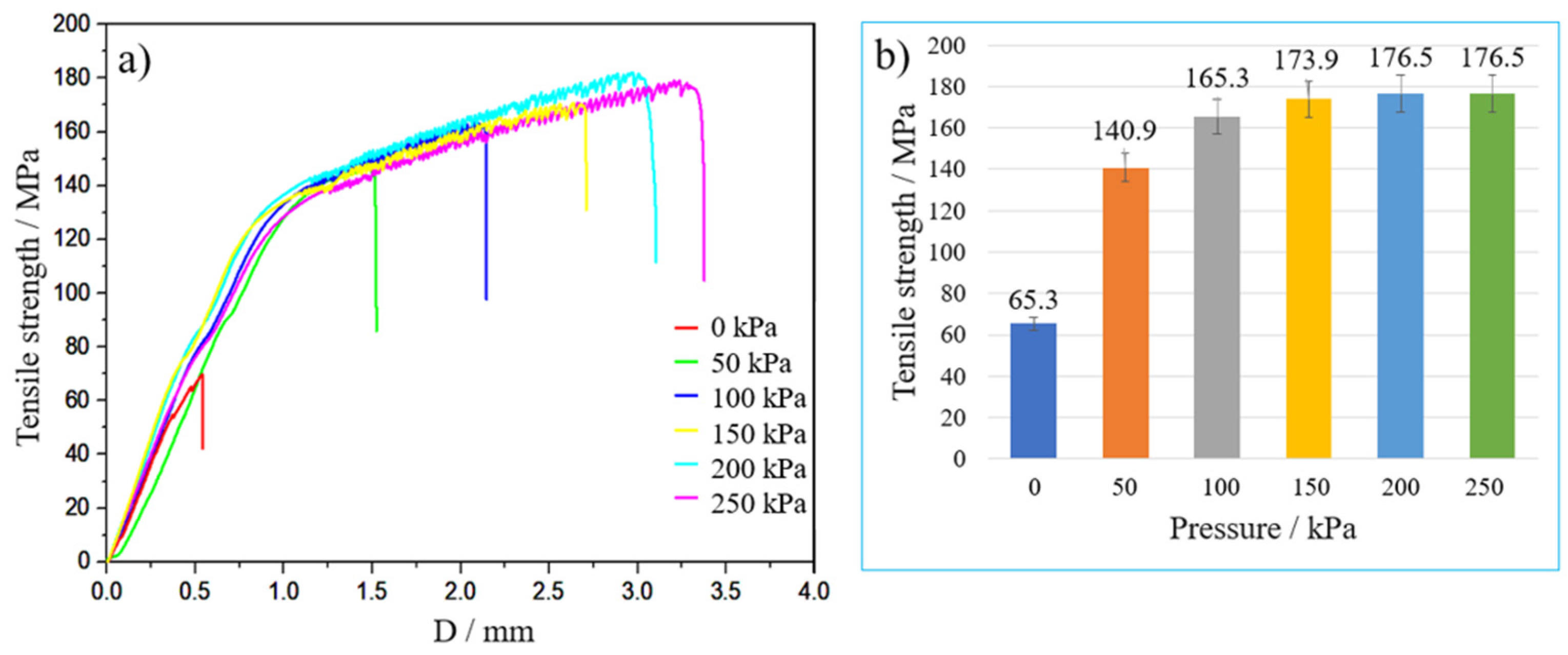
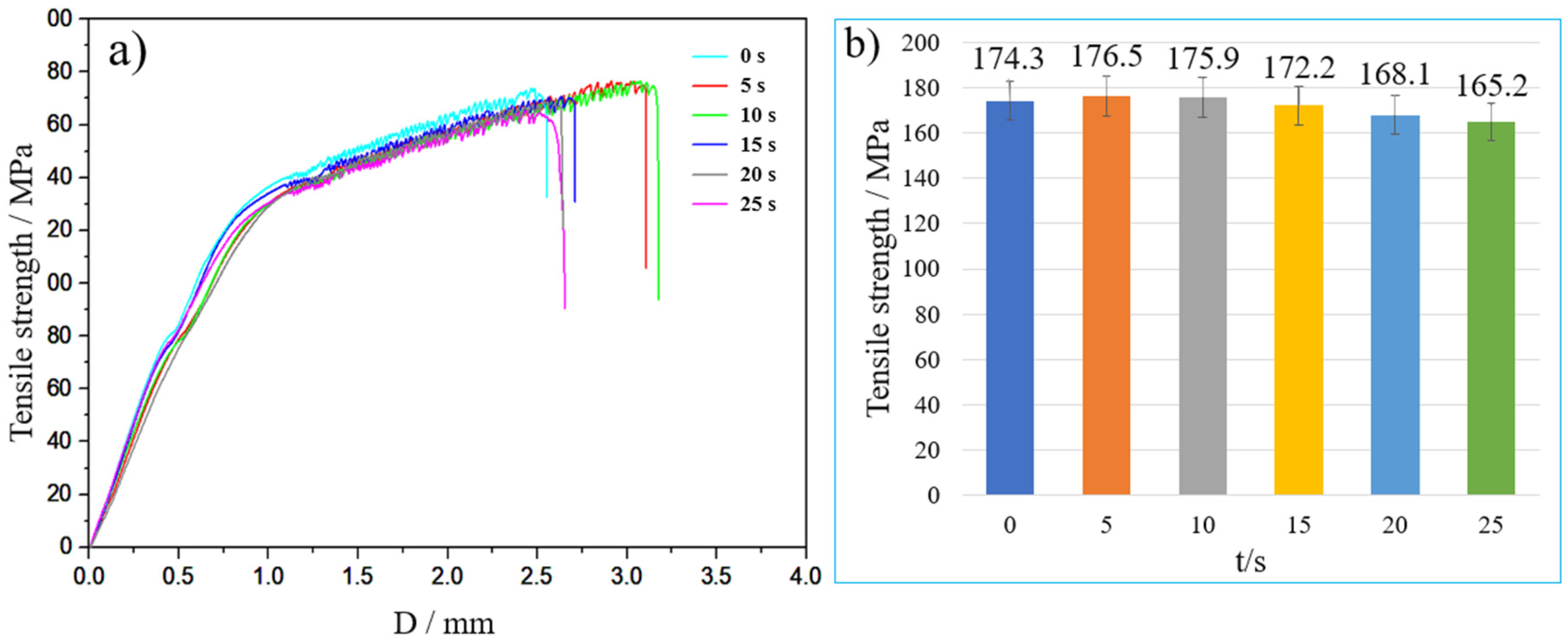
3.1. The Effect of Processing Parameters on Forming Quality

The initial welding pressures during the induction brazing process were set to be 0 kPa, 50 kPa, 100 kPa, 150 kPa, 200 kPa, and 250 kPa, respectively. Afterwards, the welding pressure decreased slowly due to the melting and flow of the resin during induction brazing. The specific parameters are listed in Table 3, and the surfaces of all the aluminum alloy samples were anodized.
Figure 6 shows the tensile property of the CFRP/5083 joints with different welding pressure. It can be observed that the tensile strength of CFRP/5083 joints increased with the increase of welding pressure. When the pressure reached 200 kPa, the tensile strength of the joint reached the maximum value of 176.5 MPa. Figure 7 shows the cross-sectional morphologies of the joints. It can be observed from Figure 7a that the CFRP and 5083 aluminum alloy could hardly be connected when no normal pressure was applied. As the pressure increased, the forming quality of the joint became better and the pore size in CFRP decreased gradually. When the pressure reached 200 kPa, the porosity defect near the interface disappeared completely. At the same time, the tensile strength of the joint reached the maximum value. Based on the test results, the optimum initial welding pressure was determined to be 200 kPa.
Similarly, in order to study the effect of welding holding time on the tensile strength of the joint, induction brazing trials with different holding time were carried out, and the specific parameters are listed in Table 4.
Figure 8 shows the tensile property of the CFRP/5083 joints with different holding time. It is obvious that the tensile strength of the joint prepared under a holding time of 5 s is the highest (176.5 MPa). Afterwards, with the increase of holding time, the tensile strength of the joints decreased slowly. The bonding between CFRP and 5083 aluminum may be ascribed to the melted PA6, which filled the voids of the anodized film to increase the bonding strength at the early stage of the induction brazing process. However, when the holding time exceeded 5 s, the melted PA6 lost continuously, resulting in less interfacial resin and reduced bonding strength.
Subsequently, 5083 plates with different surface treatments (unpolished, polished, pickled, and anodized) were connected with CFRP plates to investigate the effect of surface states on the bonding behavior of the composite joints. The pickling was the last procedure of the anodizing pre-treatment process. In addition, the other processing parameters during the induction brazing process were fixed with an induction temperature of 290 °C, a holding time of 5 s, and a normal pressure of 200 kPa. Figure 9 shows the tensile property of the CFRP/5083 joints with different surface treatments. The tensile strength of joints with unpolished and polished 5083 plates was only about 90 MPa, while the tensile strength of CFRP/pickled 5083 plate and CFRP/anodized 5083 plate reached 148.2 MPa and 176.8 MPa, respectively. Therefore, anodization is an effective method to enhance the bonding strength of the CFRP/5083 joint.
Figure 10 shows the interface morphologies of the CFRP/5083 joints with different surface treatments under a scanning electron microscope. It can be observed that there are no defects such as pores, cracks, and interface delamination in the CRFR layer, indicating that the induction brazing method can effectively protect the integrity of CFRP. Specifically, the resin at the interface could hardly be connected to the polished 5083 plate, and cracks could be clearly observed in Figure 10a. On the other hand, the bonding between the CFRP plate and the pickled 5083 plate was better due to the hackly surface of the acid-pickled 5083 plate [24], which was treated with alkaline etching and pickling. However, there were still some microcracks at the interface. After anodic oxidation, an oxide film was formed on the surface of the 5083 plate, and the anodized 5083 plate was firmly connected with the resin. Meanwhile, there were no microcracks or pores at the interface, which indicated that a sound bonding was achieved between the CFRP plate and the 5083 plate.

3.2. High Cycle Fatigue Performance

High-cycle fatigue (HCF) testing was carried out with a stress ratio of 0.1 and a frequency range of 60–85 Hz at room temperature and air condition. The number of fatigue cycles experienced by each CFRP/5083 induction brazed joint at different stress levels before fatigue fracture is shown in Figure 11. The S-N curve of CFRP/5083P-O induction brazed joint under this condition is obtained by linear fitting the points in the figure. The formula of the fitted S-N curve is expressed as:
S = 101.22 4.22 lg ( N )
When the fatigue life of the joint reaches 10 million cycles, it can be considered that the fatigue life of the joint approaches to infinite under this stress level, and this stress level is also called the fatigue limit of the joint. Under the condition that the fatigue life is 10 million cycles, the corresponding stress level is 71.68 MPa calculated by Formula 4. It is the fatigue limit of CFRP/5083 induction brazing joint under this fatigue environment. The joint will not occur fatigue fracture under the fatigue environment below this stress level. The fatigue fracture morphology of the CFRP/5083 joint at 80 MPa stress level is shown in Figure 12. It can be observed that the fracture position was located at the interface between CFRP and 5083 aluminum alloy. The oxide film on one side of the aluminum alloy surface was cracked and peeled off, and a large piece of CFRP remained on the other side of the aluminum alloy surface. Although the oxide film fell off under the influence of circulating force, most of it still remained connected with CFRP. It can be seen that it had a high bonding strength with CFRP.

4. Discussion

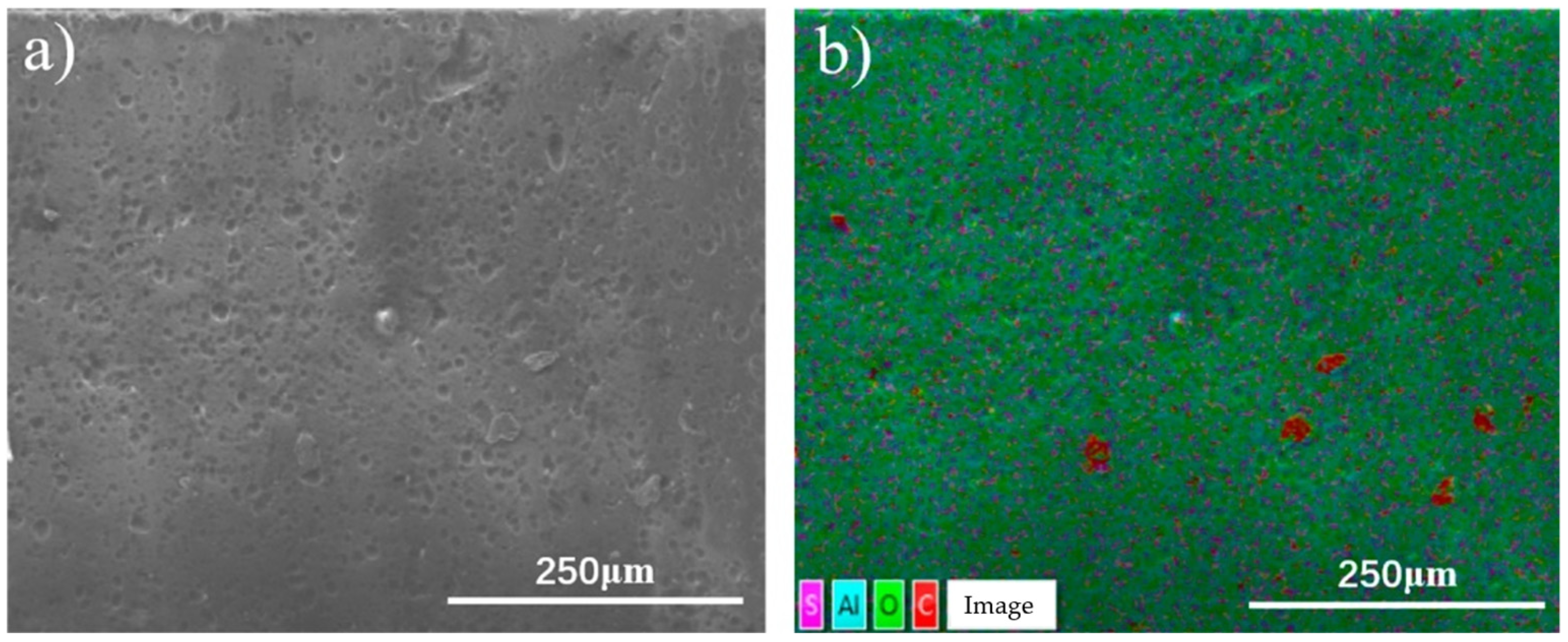
4.1. CFRP/5083 Connection Mechanism

Figure 13 shows the surface morphology of the anodic oxide film on the surface of the 5083 plate under a scanning electron microscope. At the micrometer scale, the surface morphology of the anodic oxide film presents an undulating cellular structure. At the nanometer scale, the surface morphology of anodic oxide film presents a hexagonal porous structure with uniform distribution. Meanwhile, the chemical composition of the fracture morphology of the CFRP/5083 joint after static tensile test is shown in Figure 14. It could be observed that the C element in CFRP was evenly distributed in the pores on the surface of the oxide film, which was in accordance with the previous interface morphology. It is proved that the loose and porous structure of the anodic oxide film is conducive to the formation of robust bonding between CFRP plate and 5083 plate, thus enhancing the mechanical properties of the CFRP/5083 joint.
In order to further understand the effect of anodization on the bonding behavior and strength of the CFRP/5083 joint, X-ray photoelectron spectroscopy (XPS) [25,26] was performed on the interface of the CFRP/5083 joint, and the results are shown in Figure 15. Figure 16a is the fitting diagram of O (1 s) peaks at the interface without anodization before induction brazing. The bond energy of 531.79 eV, 532.39 eV, and 534.19 eV corresponded to PA6 (C=O), Al2O3 (Al–O), and PA6 (C–O), respectively. Figure 15b is the fitting diagram of the O (1 s) peaks of the interface of CFRP/5083 joint with anodization. It can be clearly observed that the interface contained not only the diffraction peaks of C–O, C=O, and Al–O, but also a new bond energy, which was neither CFRP nor anodized Al. Similarly, by comparing the diffraction peaks in Figure 15c,d, it could be concluded that a new bonding was formed after the 5083 plate was anodized. According to the variation of the bond energy of the CFRP/5083 interface before and after anodization, and the chemical formula structure of PA6 (–[NH–(CH2)5–CO]n–) [8,27], it can be inferred that Al–O–C chemical bonds were formed at the interface [27]. Therefore, the interface of the CFRP/5083 joint without anodizing treatment only presents mechanical bonding. After the surface of the 5083 aluminum alloy was anodized, the loose and porous structure of the oxide film not only increased the mechanical bonding strength of the interface, but also led to the formation of a new bond at the CFRP/5083 interface, which enhanced the bonding strength of the joint.

4.2. Fatigue Fracture Mechanism

Figure 16 shows SEM images of the fracture surface of CFRP/5083 joint after the HCF test at 80 MPa stress levels. The figure shows the whole process of fatigue crack, including crack initiation stage, crack growth stage, and the final instant fracture. In Figure 16a, the location of the fatigue source (a hole in the oxide film) can be found through fatigue striations and river patterns, which are unique fracture morphology features during the fatigue process [28,29]. The fatigue source is mostly located in the position of pores or inclusions, as cracks are prone to initiate from defects area due to stress concentration. Similarly, the fatigue cracks of this sample also originated from the holes on the surface of the anodic oxide film. Figure 16b shows the fatigue propagation region. It can be seen that fatigue striations extend along the oxide film section and the aluminum alloy surface. It can be inferred that fatigue cracks grow along the oxide film section. Figure 16c shows the fatigue final rupture region. The fatigue striation stopped extending here. At the same time, the remaining oxide film section in the field of vision exhibited the characteristics of brittle fracture. It can be inferred that instant fracture occurred in this region.
In general, fatigue crack initiated from the hole of the oxide film, and under the influence of cyclic load, the crack slowly propagated along the section of the anodic oxide film. After the crack reached a certain length, it extended rapidly along the oxide film section, and finally fatigue fracture occurred along the oxide film section. Therefore, a part of the oxide film peeled off from the aluminum alloy base metal.
In order to further demonstrate the jointing mechanism and fatigue fracture process of CFRP/5083 joints, Figure 17 illustrates the connection mechanism and fracture process of the joint. For CFRP/polished 5083 joint, it was difficult to remove the remaining impurities in the grooves since the surface was only physically treated. The impurities between CFRP and 5083 aluminum base metal hindered the connection between CFRP and aluminum alloy, resulting in a low interfacial bonding strength. However, the pickling process (etched by NaOH and HNO3) not only effectively removed the original oxide film and impurities on the surface of the 5083 plate, but also refined the surface micro-structures, leading to the formation of a stronger mechanical interlocking structure and increasing the interface bonding strength of CFRP/5083 joint. After the surface of the 5083 plate was anodized, a layer of regular loose and porous structure was formed on the surface of the 5083 plant (Figure 17b). During the brazing process between CFRP and aluminum alloy, the melted resin flows into the loose holes of the oxide film under the pressure, forming a strong mechanical bond (Figure 17d). At the same time, XPS analysis showed that a new chemical bond was formed between the resin and the anodized film (Figure 17e), which further enhanced the bonding strength of the interface between CFRP and aluminum alloy.
During the fatigue process of the joint under axial tensile stress, shear stress was continuously loaded on the interface of the CFRP/5083 joint. Since the anodic oxide film exhibited a loose porous structure, stress concentration was prone to occur at the interface. Therefore, fatigue micro-cracks initiated from the interface between CFRP and anodic film (Figure 17f). Under the influence of cyclic force, fatigue microcracks continuously grow through adjacent holes or matrix interfaces (Figure 17g). Eventually, the anodic oxide film was separated from the base metal under shear stress, leading to the final fracture of the CFRP/5083 joint (Figure 17h). The fracture mechanism agreed well with the macroscopic fracture morphology of the CFRP/5083 joint (Figure 12).

5. Conclusions

In the present work, thermoplastic carbon fiber reinforced plastics (CFRP) plates and 5083P-O aluminum plates were successfully connected by the induction brazing method. The interfacial microstructure of the CFRP/5083 joint was observed and the interface bonding characteristics were analyzed. In the meantime, the effect of processing parameters on the bonding behavior of the CFRP/5083 joint was investigated. Subsequently, the high-cycle fatigue (HCF) performance of the CFRP/5083 joint was tested and the fatigue limit of the CFRP/5083 composite joint was obtained. The following conclusions can be drawn based on the experiments:
(1) The optimum processing parameters of the induction brazing are as follows: an induction temperature of 290 °C, a normal pressure of 200 kPa, and a holding time of 5 s.
(2) The preliminary surface treatments of the 5083 aluminum plate have a great impact on the interface bonding behavior of the CFRP/5083 joint. The tensile strength of the joint can reach the highest value of 176.5 MPa after the 5083 aluminum plate was pre-anodized.
(3) The anodization process introduced an anodic oxide film with a loose and porous structure on the surface of the 5083 plate and refined the surface micro-structures, both of which contributed to a more robust bonding between the CFRP layer and 5083 base metal. In addition, a new chemical bond, Al–O–C, was also formed at the interface of the CFRP/5083 joint and led to an enhanced tensile strength.
(4) The S–N curve of the CFRP/5083 joint was obtained and the fatigue limit was 71.68 MPa. During the HCF process of the CFRP/5083 joint, micro-cracks were initiated from the hole of oxide film and then penetrated the oxide film under axial loading. Finally, the oxide film peeled off from the 5083 metal under shear stress, leading to the fracture of the CFRP/5083 joint.

6. Expectation

The above conclusions provide an innovative idea for the connection method and joint performance of CFRP and aluminum alloy in high-speed trains or other fields. However, there are still some limitations to achieve industrial application, such as joint connection form, continuous welding equipment, pressure equipment, etc. Therefore, further exploration is needed.

Author Contributions

Conceptualization, K.G.; Data curation, H.L. and M.S.; Formal analysis, K.G. and H.L.; Methodology, M.S.; Project administration, G.G.; Supervision, G.G.; Writing—original draft, K.G. All authors have read and agreed to the published version of the manuscript.

Funding

This research was funded by the 2020 Chengdu International Cooperation Funding Project (No. 2020-GH02-00058-HZ), and the 2021 Original Scientific Research Instrument and Equipment Cultivation Project (No. 2682022ZTPV003). The APC was funded by the 2020 Chengdu International Cooperation Funding Project (No. 2020-GH02-00058-HZ).

Institutional Review Board Statement

Not applicable.

Informed Consent Statement

Not applicable.

Data Availability Statement

The raw/processed data required to reproduce these findings are available from the corresponding author upon reasonable request.

Acknowledgments

The authors would like to thank Ting Li from Shiyanjia Lab (www.shiyanjia.com) for the SEM analysis.

Conflicts of Interest

The authors declare no conflict of interest.

Nomenclature

CFRP-Carbon fiber reinforced polymer
HCF-High-cycle fatigue
σ m MPaMean normal stress
σ m a x MPaMaximum normal stress
σ m i n MPaMinimum normal stress
σ a MPaAlternating stress amplitude
R -Stress ratio
S MPaStress level
NcycleNumber of cycles to failure
XPS-X-ray photoelectron spectroscopy

References

  1. Batuwitage, C.; Fawzia, S.; Thambiratnam, D.; Al-Mahaidi, R. Evaluation of bond properties of degraded CFRP-strengthened double strap joints. Compos. Struct. 2017, 173, 144–155. [Google Scholar] [CrossRef] [Green Version]
  2. Shan, M.; Guo, K.; Gou, G.; Fu, Z.; Yang, B.; Lu, W. Effect of anodizing on galvanic corrosion behavior of T300 CFRP/5083P-O Al bolted joints. Mater. Corros. 2020, 71, 409–418. [Google Scholar] [CrossRef]
  3. Lambiase, F. Mechanical behaviour of polymer–metal hybrid joints produced by clinching using different tools. Mater. Des. 2015, 87, 606–618. [Google Scholar] [CrossRef]
  4. Hu, J.; Zhang, K.; Yang, Q.; Cheng, H.; Liu, S.; Yang, Y. Fretting behaviors of interface between CFRP and coated titanium alloy in composite interference-fit joints under service condition. Mater. Des. 2017, 134, 91–102. [Google Scholar] [CrossRef]
  5. Wei, R.; Wang, X.; Chen, C.; Zhang, X. Effect of surface treatment on the interfacial adhesion performance of aluminum foil/CFRP laminates for cryogenic propellant tanks. Mater. Des. 2017, 116, 188–198. [Google Scholar] [CrossRef]
  6. Jung, K.W.; Kawahito, Y.; Takahashi, M.; Katayama, S. Laser direct joining of carbon fiber reinforced plastic to zinc-coated steel. Mater. Des. 2013, 47, 179–188. [Google Scholar] [CrossRef]
  7. Zhang, Z.; Shan, J.; Tan, X.; Zhang, J. Improvement of the laser joining of CFRP and aluminum via laser pre-treatment. Int. J. Adv. Manuf. Technol. 2017, 90, 3465–3472. [Google Scholar] [CrossRef]
  8. Zhang, Z.; Shan, J.; Tan, X. Evaluation of the CFRP grafting and its influence on the laser joining CFRP to aluminum alloy. J. Adhes. Sci. Technol. 2018, 32, 390–406. [Google Scholar] [CrossRef]
  9. Tan, X.; Zhang, J.; Shan, J.; Yang, S.; Ren, J. Characteristics and formation mechanism of porosities in CFRP during laser joining of CFRP and steel. Compos. Part B Eng. 2015, 70, 35–43. [Google Scholar] [CrossRef]
  10. Esteves, J.V.; Goushegir, S.M.; dos Santos, J.F.; Canto, L.B.; Hage, E.; Amancio-Filho, S.T. Friction spot joining of aluminum AA6181-T4 and carbon fiber-reinforced poly(phenylene sulfide): Effects of process parameters on the microstructure and mechanical strength. Mater. Des. 2015, 66, 437–445. [Google Scholar] [CrossRef]
  11. André, N.M.; Goushegir, S.M.; dos Santos, J.F.; Canto, L.B.; Amancio-Filho, S.T. Friction Spot Joining of aluminum alloy 2024-T3 and carbon-fiber-reinforced poly(phenylene sulfide) laminate with additional PPS film interlayer: Microstructure, mechanical strength and failure mechanisms. Compos. Part B Eng. 2016, 94, 197–208. [Google Scholar] [CrossRef]
  12. Goushegir, S.M. Friction spot joining (FSpJ) of aluminum-CFRP hybrid structures. Weld World 2016, 60, 1073–1093. [Google Scholar] [CrossRef] [Green Version]
  13. Balle, F.; Wagner, G.; Eifler, D. Ultrasonic spot welding of aluminum sheet/carbon fiber reinforced polymer—Joints. Materwiss Werksttech 2007, 38, 934–938. [Google Scholar] [CrossRef]
  14. Lionetto, F.; Balle, F.; Maffezzoli, A. Hybrid ultrasonic spot welding of aluminum to carbon fiber reinforced epoxy composites. J. Mater. Process. Technol. 2017, 247, 289–295. [Google Scholar] [CrossRef]
  15. Balle, F.; Huxhold, S.; Emrich, S.; Wagner, G.; Kopnarski, M.; Eifler, D. Influence of Heat Treatments on the Mechanical Properties of Ultrasonic Welded AA 2024/CF-PA66-Joints. Adv. Eng. Mater. 2013, 15, 837–845. [Google Scholar] [CrossRef]
  16. Balle, F.; Huxhold, S.; Wagner, G.; Eifler, D. Damage Monitoring of Ultrasonically Welded Aluminum/CFRP-Joints by Electrical Resistance Measurements. Procedia Eng. 2011, 10, 433–438. [Google Scholar] [CrossRef] [Green Version]
  17. Nagatsuka, K.; Xiao, B.; Wu, L.; Natata, K.; Saeki, S.; Kitamoto, Y.; Iwamoto, Y. Dissimilar materials joining of metal/carbon fiber reinforced plastic by resistance spot welding. Quart. J. Jpn. Weld. Soc. 2018, 32, 505–512. [Google Scholar]
  18. Zhu, J.W.Y.W. An Experimental Study on the Strength and Life Comparison of the Dismaterial Lap and Butt Weld at High Temperature. Gas Turb. Exp. Res. 2003, 4, 18–20. [Google Scholar]
  19. Nobile, R.; Panella, F.W.; Pirinu, A.; Saponaro, A. Full-field monitoring methods for damage analysis on aeronautical CFRP specimens under fatigue loads. Mater. Sci. Eng. 2022, 1214, 12008. [Google Scholar] [CrossRef]
  20. Huang, J.; Yang, H.; Liu, W.; Zhang, K.; Huang, A. Confidence level and reliability analysis of the fatigue life of CFRP laminates predicted based on fracture fatigue entropy. Int. J. Fatigue 2022, 156, 106659. [Google Scholar] [CrossRef]
  21. He, Z.; Luo, Q.; Li, Q.; Zheng, G.; Sun, G. Fatigue behavior of CFRP/Al adhesive joints—Failure mechanisms study using digital image correlation (DIC) technique. Thin Wall. Struct. 2022, 174, 109075. [Google Scholar] [CrossRef]
  22. Kapidžić, Z.; Granados, D.L.Á.; Arias, J.A.M.; Aguilera, M.J.Q.; Rodríguez, J.P.C.; Callejas, J.C.G. Bolt fatigue in CFRP joints. Int. J. Fatigue 2022, 164, 107138. [Google Scholar] [CrossRef]
  23. Strzelecki, P.; Sempruch, J.; Nowicki, K. Comparing Guidelines Concerning Construction of the S-N Curve within Limited Fatigue Life Range. Pol. Marit. Res. 2015, 22, 67–74. [Google Scholar] [CrossRef] [Green Version]
  24. Yu, Y.; You, S.; Du, J.; Zhang, P.; Dai, Y.; Liu, M.; Jiang, B.; Ren, N.; Zou, J. Ti3+-self-doped TiO2 with multiple crystal-phases anchored on acid-pickled ZIF-67-derived Co3O4@N-doped graphitized-carbon as a durable catalyst for oxygen reduction in alkaline and acid media. Chem. Eng. J. 2021, 403, 126441. [Google Scholar] [CrossRef]
  25. Arangdad, K.; Yildirim, E.; Detwiler, A.; Cleven, C.D.; Burk, C.; Shamey, R.; Pasquinelli, M.A.; Freeman, H.; El-Shafei, A. X-ray photoelectron spectroscopy study on the photodegradation of copolyester model compounds. J. Appl. Polym. Sci. 2021, 138, 49661. [Google Scholar] [CrossRef]
  26. Melandri, S.; Evangelist, L.; Canola, S.; Sa’adeh, H.; Calabrese, C.; Coreno, M.; Grazioli, C.; Prince, K.C.; Negri, F.; Maris, A. Chlorination and tautomerism: A computational and UPS/XPS study of 2-hydroxypyridine ⇌ 2-pyridone equilibrium. Phys. Chem. Chem. Phys. 2020, 22, 13440–13455. [Google Scholar] [CrossRef]
  27. Zhang, Z.; Shan, J.-G.; Tan, S.-H.; Zhang, J. Effect of anodizing pretreatment on laser joining CFRP to aluminum alloy A6061. Int. J. Adhe. Adhes. 2016, 70, 142–151. [Google Scholar] [CrossRef]
  28. Singh Raman, R.K.; Jafari, S.; Harandi, S.E. Corrosion fatigue fracture of magnesium alloys in bioimplant applications: A review. Eng. Fract. Mech. 2015, 137, 97–108. [Google Scholar] [CrossRef]
  29. Horstemeyer, M. High cycle fatigue of a die cast AZ91E-T4 magnesium alloy. Acta Mater. 2004, 52, 1327–1336. [Google Scholar] [CrossRef]
Figure 1. (a) High-speed maglev train, (b) Schematic diagram of carbon fiber train body structure.
Coatings 12 01559 g001
Figure 2. Flow chart of the joining process and investigation of bonding strength.
Coatings 12 01559 g002
Figure 3. (a) Macro-morphology of CFRP; (b) micro-morphology of CFRP; (c) enlarged view in (b).
Coatings 12 01559 g003
Figure 4. Schematic diagram of the anodizing device.
Coatings 12 01559 g004
Figure 5. (a) Induction brazing apparatus; (b) Schematic diagram of brazing process; (c) Dimensions of the CFRP plate and 5083 P-O plate.
Coatings 12 01559 g005
Figure 6. Tensile property of CFRP/5083 joints with different welding pressures. (a) Stress–displacement curves; (b) tensile strength of CFRP/5083 joints.
Coatings 12 01559 g006
Figure 7. Interface morphologies of joints with different welding pressures. (a) 0 kPa; (b) 50 kPa; (c) 100 kPa; (d) 150 kPa; (e) 200 kPa; (f) 250 kPa.
Coatings 12 01559 g007
Figure 8. Tensile property of the joints with different holding time. (a) Stress–displacement curves; (b) tensile strength of CFRP/5083 joints.
Coatings 12 01559 g008
Figure 9. Tensile property of CFRP/5083 joints with different surface treatments. (a) Stress–displacement curves; (b) tensile strength of CFRP/5083 joints.
Coatings 12 01559 g009
Figure 10. Interface morphologies of CFRP/5083 joints with different surface treatments. (a) CFRP and polished 5083 plate; (b) CFRP and pickled 5083 plate; (c) CFRP and anodized 5083 plate.
Coatings 12 01559 g010
Figure 11. S–N curve of the CFRP/5083 joints.
Coatings 12 01559 g011
Figure 12. Fatigue fracture morphology of the CFRP/5083 joint.
Coatings 12 01559 g012
Figure 13. Surface morphology of anodic oxide film on the surface of 5083 plate.
Coatings 12 01559 g013
Figure 14. Micro-morphology of the fractured surface of CFRP/5083 joint after tensile testing. (a) Electronic image; (b) element distribution.
Coatings 12 01559 g014
Figure 15. XPS results on the interface of CFRP/5083 joints. (a) the bond energy of O at the interface of un-anodized joints; (b) bond energy of O at the interface of anodized joints; (c) bond energy of Al at the interface of un-anodized joints; (d) bond energy of Al at the interface of anodized joints.
Coatings 12 01559 g015
Figure 16. Fatigue fracture morphology of CFRP/5083 joints under a maximum stress of 80 MPa. (a) Fatigue crack source; (b) Crack growth area; (c) Final fracture area.
Coatings 12 01559 g016
Figure 17. Connection mechanism and fracture process of CFRP/5083 joint fabricated by induction brazing. (a) 5083P-O aluminum plate; (b) Structure diagram of anodic oxide film; (c) CFRP plate; (d) Schematic diagram of joint structure; (e) Interfacial chemical bond; (f) Fatigue crack initiation; (g) Fatigue crack initiation; (h) Fatigue fracture.
Coatings 12 01559 g017
Table 1. Chemical composition of 5083P-O aluminum (wt.%).
SiCuMgZnMnTiCrFeAl
≤0.40≤0.104.0–4.9≤0.250.40–1.0≤0.150.05–0.250–0.4Bal.
Table 2. Chemical composition of the anodizing solution.
Scheme 2.H2SO4H3PO4H3BO3H2O
Concentration120 g/L60 g/L3 g/LBal.
Table 3. Processing parameters with different pressure.
No.T [°C]t [s]P1 [kPa]P2 [kPa]
1290500
2505
310016.7
415040
520043.3
625083.3
Note: P1 is the pressure before welding, P2 is the residual pressure after welding.
Table 4. Processing parameters with different holding time.
No.T [°C]P [kPa]t [s]
12902000
25
310
415
520
625
Publisher’s Note: MDPI stays neutral with regard to jurisdictional claims in published maps and institutional affiliations.

