Article

Physico-Chemical Origins of Electrical Characteristics and Instabilities in Solution-Processed ZnSnO Thin-Film Transistors

1
School of Electronic and Electrical Engineering, Kyungpook National University, 80 Daehakro, Bukgu, Daegu 41566, Korea
2
School of Electronics Engineering, Kyungpook National University, 80 Daehakro, Bukgu, Daegu 41566, Korea
*
Authors to whom correspondence should be addressed.
Present address: LG Display, Paju 10845, Korea.
Coatings 2022, 12(10), 1534; https://doi.org/10.3390/coatings12101534
Submission received: 20 September 2022 / Revised: 7 October 2022 / Accepted: 11 October 2022 / Published: 13 October 2022
(This article belongs to the Section Thin Films)

Abstract

:
We investigate the physico-chemical origins that determine the transistor characteristics and stabilities in sol-gel processed zinc tin oxide (ZTO) thin-film transistors (TFTs). ZTO solutions with Sn/(Sn+Zn) molar ratios from 0.3 to 0.6 were synthesized to demonstrate the underlying mechanism of the electrical characteristics and bias-induced instabilities. As the Sn/(Sn+Zn) ratio of ZTO is increased, the threshold voltage of the ZTO TFTs negatively shifts owing to the gradual increase in the ratio of oxygen vacancies. The ZTO TFTs with an Sn/(Sn+Zn) ratio of 0.4 exhibit highest saturation mobility of 1.56 cm2/Vs lowest subthreshold swing and hysteresis of 0.44 V/dec and 0.29 V, respectively, due to the desirable atomic states of ZTO thin film. Furthermore, these also exhibit outstanding positive bias stability due to the low trap density at the semiconductor-dielectric interface. On the other hand, the negative bias stress-induced instability gradually increases as the proportion of tin increases because the negative bias stress instability originates from the ionization of oxygen vacancies. These results will contribute to the optimization of the composition ratio in rare-metal-free oxide semiconductors for next-generation low-cost electronics.

1. Introduction

Recently, oxide thin-film transistors (TFTs) have been considered as one of the most desirable unit devices for various electronic applications, including organic light-emitting diode (OLED) displays, owing to their advantages of low leakage current, high optical transparency, and high flexibility [1,2,3]. In particular, amorphous oxide semiconductors (AOS) have been commercialized because of their effective charge transport characteristics, although those have an amorphous phase compared to amorphous silicon semiconductors. Effective electron transport of the AOS could be achieved because of the overlap of the internal spherically symmetric metal s-orbitals, achieving high electron mobility [4,5,6,7,8]. Among many AOS materials, indium gallium zinc oxide is the representative oxide semiconductor for TFT channel layers [9,10,11,12,13]. Unfortunately, indium and gallium are relatively expensive rare metals; therefore, those are not cost-effective [14,15]. Accordingly, many researchers have attempted to find a cheap alternative metal component for oxide TFTs [15]. For example, zinc tin oxide (ZTO) has been studied as a newly emerging amorphous oxide semiconductor owing to its potential to achieve high mobility and an amorphous phase despite the absence of rare metal [16].
Along with the electrical characteristics of TFTs, their bias stability is one of the most important factors for practical electronic applications. The bias stability determines the lifespan of a device [17]. The deposition of an oxide thin film through sputtering, a physical vapor deposition (PVD) method, is currently the most widely used method owing to the outstanding electrical characteristics and bias stability of sputtered AOS TFTs [18]. Despite these merits, PVD has distinct limitations in terms of scalability and productivity because a high vacuum is required for thin-film deposition. In contrast, solution-processing techniques have advantages, such as low-cost fabrication, high-throughput, and simplicity [19]. However, the electrical stability of TFTs fabricated by solution processing methods is inferior to those fabricated by PVD methods [20]. Therefore, in-depth studies to improve the electrical properties and bias instability of sol-gel processed ZTO TFTs are required to realize next-generation electronic applications.
In this study, physico-chemical origins that affect the operational properties and bias instabilities of solution-processed ZTO TFTs were demonstrated by modulating the metal composition ratio. The Sn/(Sn+Zn) ratio was controlled from 0.3 to 0.6 by using a chloride precursor. Atomic bonding states according to composition ratio were examined through X-ray photoelectron spectroscopy (XPS). In addition, the physical morphology of ZTO semiconductors with respect to various Sn/(Sn+Zn) ratios was investigated using atomic force microscopy (AFM). The influence of the composition ratio on the electrical characteristics was demonstrated based on the physico-chemical analysis of ZTO thin films. The ZTO TFTs with an Sn/(Sn+Zn) ratio of 0.4 exhibited outstanding electrical properties with the highest saturation mobility (μsat) of 1.56 cm2/Vs. Furthermore, the positive- and negative-bias stress-induced instabilities were investigated for high-performance and stable solution-processed rare-metal-free oxide TFTs.

2. Materials and Methods

ZTO solutions of 0.17 M with Sn/(Sn+Zn) ratios of 0.3, 0.4, 0.5, and 0.6 were synthesized by dissolving zinc (II) chloride hydrate (ZnCl2·2H2O; Sigma-Aldrich, Saint Louis, MO, USA) and tin chloride hydrate (SnCl2·H2O; Sigma-Aldrich, Saint Louis, MO, USA) in 2-methoxyethanol (CH3OCH2CH2OH; Sigma-Aldrich, Saint Louis, MO, USA). The solutions were sonicated for 1200 s at room temperature to obtain homogeneous and clear solutions. Figure 1 depicts the device structure of the solution-processed ZTO TFTs used in this study. Wafers with heavily doped Si and thermally grown SiO2 were used as the gate electrode and insulator, respectively. The Si/SiO2 wafers were cleaned in acetone, isopropanol, and deionized water for 10 min each by using ultrasonication. The cleaned substrates were blown with nitrogen and heated at 120 °C for 10 min to completely dry and remove moisture. Next, ultraviolet ozone was irradiated on the SiO2 surface for 30 min to generate a hydrophilic surface. The prepared ZTO solution was deposited onto the substrate at 3000 rpm by using spin coating. The deposited ZTO semiconductor thin films were pre-annealed at 120 °C for 30 min for solidification. Pre-annealing is a stage to form a solidified thin film by evaporating the solvent in the ZTO solution. When the pre-annealing temperature is too high, the roughness of the thin film is degraded, and pinholes or pore sites are formed, which can result in deterioration of electrical characteristics and bias stability [21]. Thus, we have optimized the pre-annealing temperature through our previous study [21]. After pre-annealing, the ZTO-deposited Si/SiO2 wafers were annealed at 500 °C in air for 1 h in a tube furnace. Post-annealing activates the semiconductor by inducing condensation and densification of the thin film [3]. The annealing temperature differs depending on the precursor, metal cation, and solvent. The desirable annealing temperature for ZTO TFTs used in this study was obtained through the study of reported articles and our TFT experiments [3,14,15,21]. For the source and drain electrodes, 50 nm-thick aluminum was deposited on the ZTO semiconductors using a thermal evaporator. The channel length (L) and width (W) of the ZTO TFTs were 100 and 1000 μm, respectively. Finally, the fabricated ZTO TFTs were placed in a low-pressure thermal desiccator for 1 h. The low-pressure thermal treatment induces hydrophobic surface and densification of the thin film. Thus, this process improves the switching characteristics of solution-processed ZTO TFTs. XPS (Thermo Fisher Scientific, Waltham, MA, USA) was used to demonstrate the atomic bonding states of the semiconductor thin films. Non-contact-mode AFM (NX20, Park Systems, Suwon-si, Korea) was used to investigate the surface roughness and morphological characteristics of the ZTO. Electrical characteristics and bias stability were measured at about 25 °C in a dark chamber to eliminate the effects of light on devices.

3. Results and Discussion

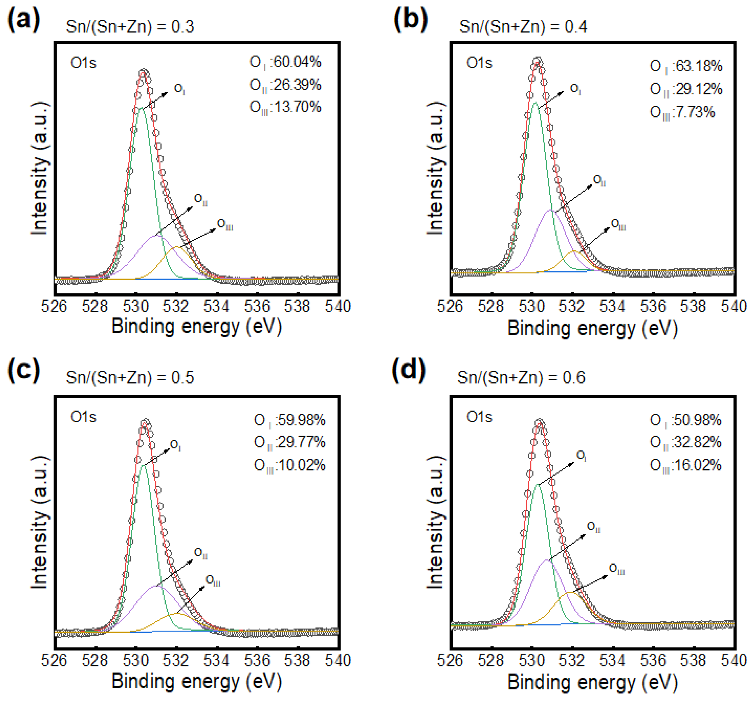
The atomic binding states of ZTO semiconductors with various Sn/(Sn+Zn) molar ratios were analyzed to understand the impacts of the metal composition ratio on the chemical characteristics of the ZTO thin films. Figure 2a–d show the XPS analysis of the ZTO thin films with Sn/(Sn+Zn) molar ratios of 0.3, 0.4, 0.5, and 0.6, respectively. The O 1s spectra were deconvoluted into three peaks to evaluate the chemical changes. The three peaks at 530.3, 531.0, and 531.9 eV represent metal oxide (M–O) bonds, oxygen vacancies (VO), and metal hydroxyl (M–OH), respectively [22,23]. The M–O ratios of the ZTO thin films with Sn/(Sn+Zn) ratios of 0.3, 0.4, 0.5, and 0.6 are 60.04%, 63.18%, 59.98%, and 50.98%, respectively. The M–O intensity of the ZTO with a ratio of 0.4 is the highest compared to others. In addition, the M–O intensity significantly decreased when the ratio reduced to 0.6. This indicates that the carrier transport paths of ZTO could be well organized at a ratio of 0.3, because electrons are mainly transported through M–O [24,25]. Moreover, Vo increased with increasing Sn ratio. The Vo ratio increased from 26.39% to 32.82% as the composition ratio increased from 0.3 to 0.6. Generally, Vo generates free electrons in oxide semiconductors [26]. Thus, this result indicates that an increase in the Sn ratio in ZTO semiconductors contributes to an increase in electron concentration. The M–OH contents of the ZTO films with ratios of 0.3, 0.4, 0.5, and 0.6 are 13.7%, 7.73%, 10.0%, and 16.0%, respectively. When the composition ratio was 0.4, the lowest M–OH ratio was obtained in the ZTO film. M–OH can act as an acceptor-like defect in oxide semiconductors [27]; thus, the control and minimization of M–OH should be considered in the fabrication of oxide semiconductors for obtaining highly stable oxide TFTs.
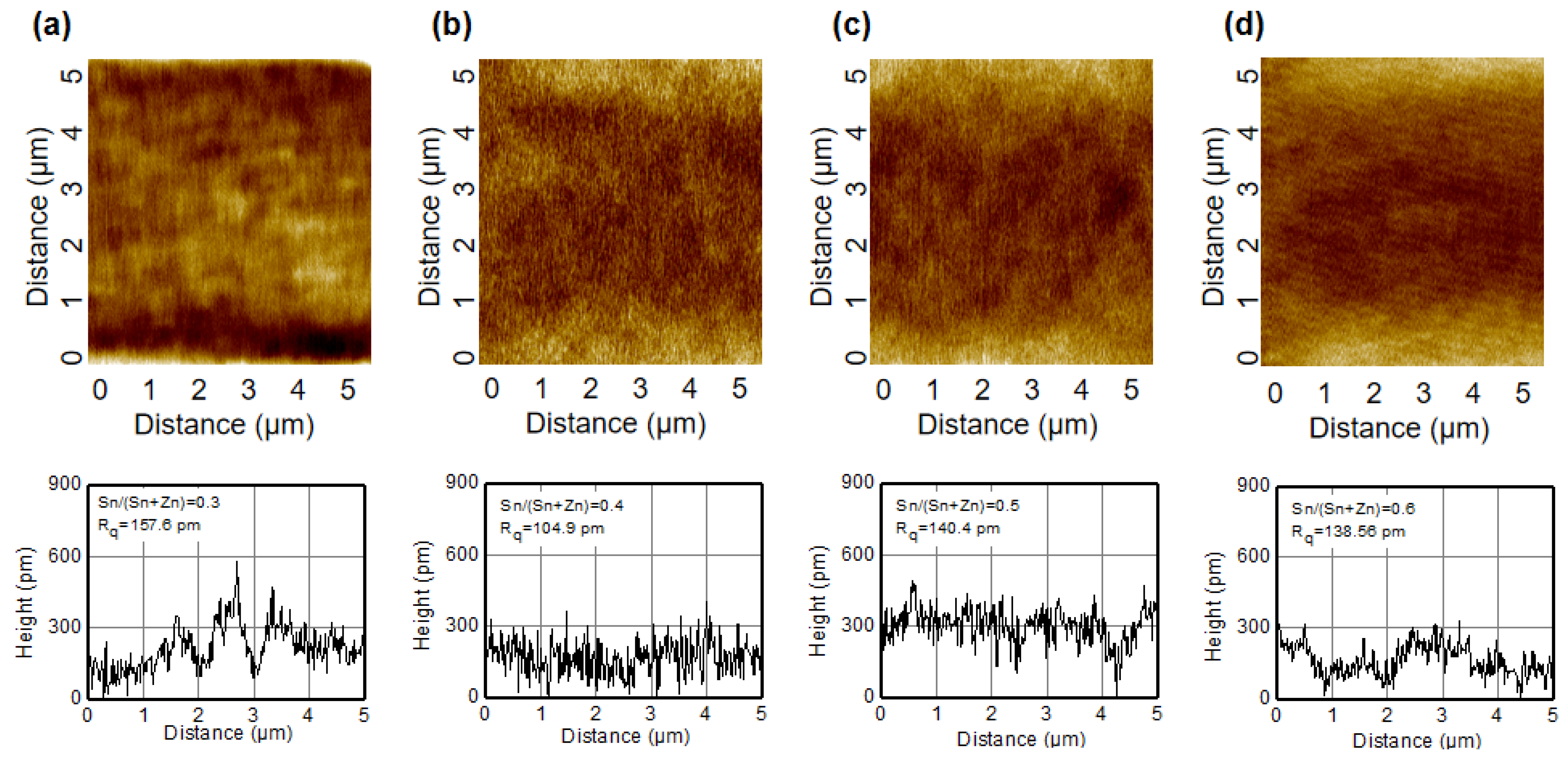
The physical morphology and roughness properties of ZTO thin films according to composition ratio was examined by using AFM analysis. The AFM images of the semiconductors with Sn/(Sn+Zn) ratios of 0.3, 0.4, 0.5, and 0.6 are shown in Figure 3a–d, respectively. The film roughness of the ZTO semiconductors with the ratios of 0.3, 0.4, 0.5, and 0.6 were 157.6, 104.9, 140.4, and 138.56 pm, respectively. The ZTO thin film with a ratio of 0.4 exhibited the lowest surface roughness compared to ZTO thin films with other composition ratios. Considering the atomic bonding states captured in the XPS analysis and surface roughness depicted in the AFM analysis, a composition ratio of 0.4 is determined to be the most optimized composition ratio, which could yield desirable physico-chemical properties in ZTO TFTs [28,29,30].
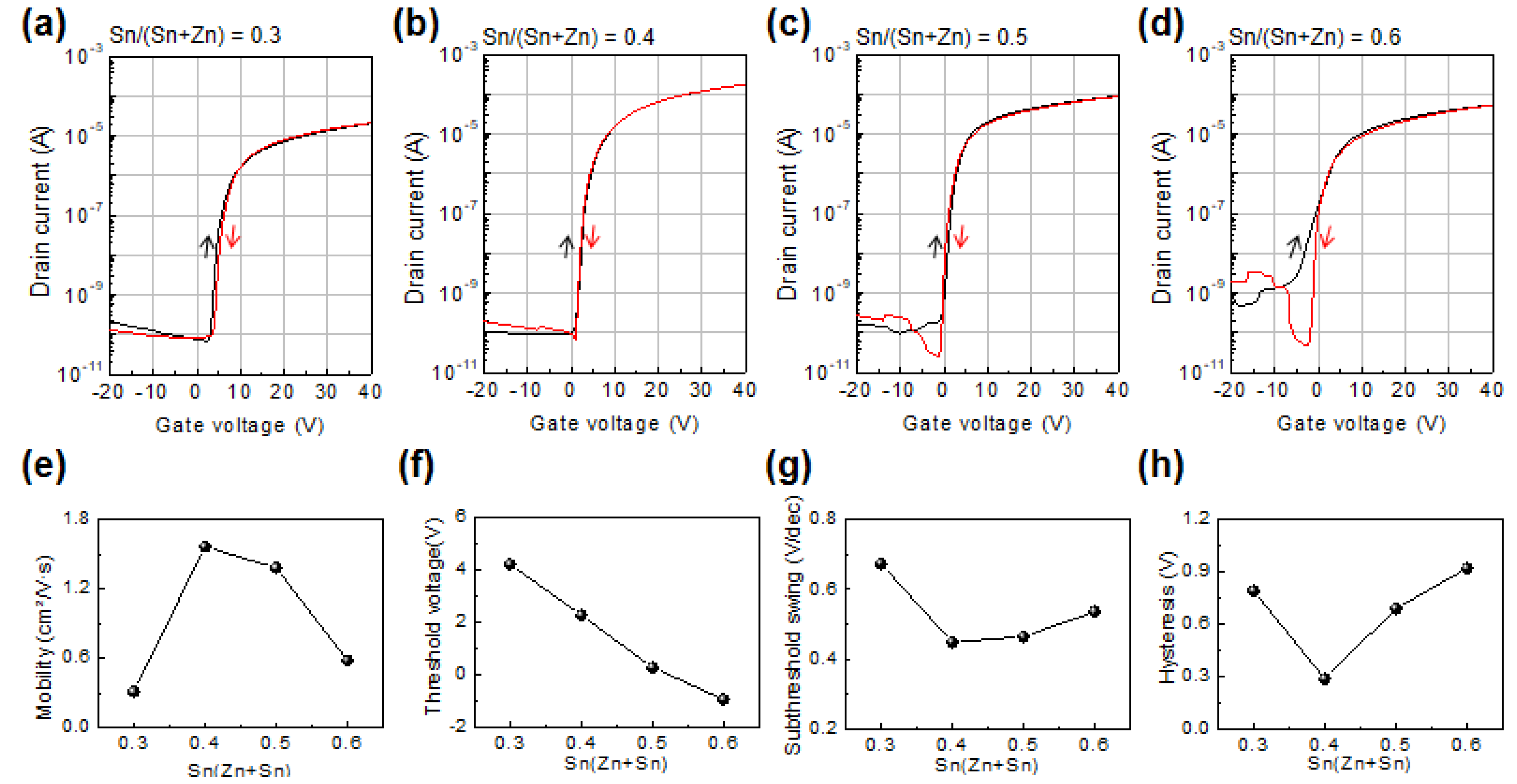
Bottom-gate top-contact structure ZTO TFTs were fabricated to evaluate their electrical characteristics and stabilities. Figure 4a–d show the transfer characteristics of the ZTO TFTs with Sn/(Sn+Zn) ratios of 0.3, 0.4, 0.5, and 0.6, respectively. The black and red lines indicate the transfer characteristic curves with forward and backward sweeps, respectively. A drain voltage (VD) of 40 V was applied to obtain the transfer characteristic curves. μsat is extracted using the following equation:
μ sat = 2 L WC i I D , sat V G 2
where Ci, VG, and ID,sat are the dielectric capacitance per unit area, gate voltage, and drain current in saturation region, respectively. The μsat values of the ZTO TFTs with Sn/(Sn+Zn) ratios of 0.3, 0.4, 0.5, and 0.6 are 0.31, 1.56, 1.38, and 0.58 cm2/Vs, respectively. This might be attributed to the high M-O ratio of the ZTO semiconductors with a ratio of 0.4, as shown in Figure 2b. In addition, the lowest subthreshold swing (SS) of 0.44 V/dec and hysteresis of 0.29 V are obtained in the ZTO TFTs with a ratio of 0.4. The M-OH bonding could act as trap sites for free electrons, thereby yielding high SS and clockwise hysteresis in TFTs [31]. In this regard, it is reasonable to interpret that the lowest SS and hysteresis characteristics of the ZTO TFTs with a ratio of 0.4 originate from the low M-OH and high M-O content in ZTO films with a ratio of 0.4. Furthermore, the trap density at the gate dielectric-semiconductor interface can be evaluated using the following equation [32]:
N T = SSlog e kT q 1 C i q
where q, k, T, and NT are the electron charge, dielectric constant, temperature, and total trap density, respectively. Based on Equation (2), the high SS value of a device implies that it has inferior dielectric-semiconductor interface characteristics with a high electron trap density. Clockwise hysteresis is generally induced by electron trapping at the gate dielectric-semiconductor interface at a positive gate bias [33]. Thus, the good interface property of ZTO TFTs with a ratio of 0.4 also contribute toward achieving the outstanding electrical characteristics, such as high μsat, low SS, and clockwise hysteresis. In addition, it is known that the Zn atom can act as an acceptor at the ZTO thin film with a high Sn/(Sn+Zn) ratio because Zn atom play a role as impurity which can substitute for the Sn site [34]. This is a reasonable inference consistent with the electrical characteristic results, especially SS and μsat of ZTO TFTs with high Sn/(Sn+Zn) ratio, of our study. Meanwhile, the Vth of ZTO TFTs is negatively shifted with an increase in Sn concentration. This is because Vo increases as the Sn concentration ratio increases, as depicted in Figure 2, which results in an increase in the carrier concentration. The high carrier concentration of ZTO semiconductors induces easy accumulation even at low VG. Figure 4e–h plots the tendencies of μsat, Vth, SS, and hysteresis of the ZTO TFTs as a function of the composition ratio, respectively. This result indicates that the Sn/(Sn+Zn) ratio of 0.4 is the optimal composition ratio for obtaining high-mobility and stable oxide TFTs with desirable switching characteristics.
The bias stability of TFTs is a crucial factor in practical TFT-based electronic device applications [35]. The positive gate bias stress (PBS)-induced instability of solution-processed ZTO TFTs according to the Sn/(Sn+Zn) ratio was investigated. Figure 5a–d plots the transfer characteristics as a function of PBS for solution-processed ZTO TFTs with Sn/(Sn+Zn) ratios of 0.3, 0.4, 0.5, and 0.6, respectively. The PBS test was performed for 1000 s at VG = 20 V and VD = 0 V. The ∆Vth values of ZTO TFTs with Sn/(Sn+Zn) ratios of 0.3, 0.4, 0.5, and 0.6 are 12.12, 4.24, 8.71, and 9.88 V, respectively. The lowest Vth shift due to PBS in TFTs with a ratio of 0.4 is attributed to the low trap density at the dielectric-semiconductor interface. As described in Figure 4 and Equation (2), ZTO TFTs with an Sn/(Sn+Zn) ratio of 0.4 have the lowest interface trap density. The interface traps might originate from the high ratio of M-OH acceptor-like traps owing to the non-optimal composition ratio [36]. Under a positive gate bias, some of the accumulated carriers could be trapped at the interface trap states or injected into the gate dielectric owing to the vertical electric field. Because the same thermally grown SiO2 was used as the gate dielectric in this study for all TFTs, the difference in the PBS-induced instability in ZTO TFTs with various Sn/(Sn+Zn) ratios mainly originates from the differences in the gate dielectric-semiconductor interface characteristics. In addition, the Vth of the ZTO TFTs is positively shifted without a change in SS, regardless of the Sn/(Sn+Zn) ratio. This phenomenon suggests that the PBS-induced instability in this study is due to the electron trapping at the interface and injection to gate dielectric, rather than defect creation models [37].
Figure 6a–d depicts transfer characteristics as a function of negative bias stress (NBS) time for ZTO TFTs with Sn/(Sn+Zn) ratios of 0.3, 0.4, 0.5, and 0.6, respectively. In the NBS test conducted on ZTO TFTs, VG = −20 V and VD = 0 V were applied for 1000 s. As the NBS time increases, the Vth shifts in the negative direction regardless of Sn/(Sn+Zn) ratio. In particular, as the concentration ratio increases, the negative shift caused by NBS tends to increase. Unlike that observed under PBS conditions, electrons do not accumulate under NBS conditions; thus, they cannot be trapped at the gate dielectric-semiconductor interface or injected into the gate dielectric. The negative Vth shift could be basically caused by hole trapping at the interface [38]. However, hole trapping at the dielectric-semiconductor interface due to NBS is not a reasonable mechanism to explain the instability if SS of oxide TFTs increases under conditions such as NBS or negative bias illumination stress. In this case, the shift in Vth due to NBS originates from the ionization of Vo. When the fermi level of the ZTO approaches the valance band maximum due to a strong negative gate bias, the Vo formation energy increases, while the Vo2+ formation energy decreases [39,40]. Therefore, under NBS conditions, Vo could generate two free electrons and be easily ionized into Vo2+ [40]. Considering the XPS result depicted in Figure 2, Vth shift in ZTO TFTs is assumed to originate owing to the double ionization of Vo. The increase in Sn/(Sn+Zn) ratio induces a Vo increase, so that the ZTO TFTs with high Sn/(Sn+Zn) ratios show dramatic Vth shift in the negative direction. This result suggests that understanding the effect of composition ratio and its optimization is essential to achieve the desirable Vth and negative bias stability of sol-gel processed ZTO TFTs.

4. Conclusions

In summary, the physico-chemical origins, electrical characteristics, and bias stress-induced instability of solution-processed ZTO TFTs were investigated by controlling the metal composition ratio. The change in the Sn/(Sn+Zn) ratio in the ZTO semiconductor induces a considerable change in the microstructure, thereby affecting the electrical properties and operational stability of ZTO TFTs. An optimal ZTO thin film was obtained at an Sn/(Sn+Zn) ratio of 0.4. XPS analysis confirmed that the ZTO thin film with an Sn/(Sn+Zn) ratio of 0.4 attained the highest M-O and lowest M-OH ratios of 63.18% and 7.73%, respectively. Consequently, solution-processed ZTO TFTs with an Sn/(Sn+Zn) ratio of 0.4 exhibited the highest μsat and SS of 1.56 cm2/Vs and 0.44 V/dec, respectively. Furthermore, ZTO TFTs with an Sn/(Sn+Zn) ratio of 0.4 exhibited the highest stability under PBS owing to the good dielectric-semiconductor interface property and low M-OH ratio of the ZTO semiconductor. In addition, the NBS-induced instability of ZTO TFTs with an Sn/(Sn+Zn) ratio of 0.4 was not significant compared to those observed ratios of 0.5 and 0.6 owing to the lower Vo ratio. In short, this study contributes to the optimization of the compositional ratio for manufacturing high-performance and stable solution-processed oxide TFTs.

Author Contributions

Conceptualization: Z.W., D.-K.K. and J.-H.B.; Investigation: Z.W., D.-K.K., S.-H.J. and Y.-J.H.; Validation: S.-H.L., J.J. and I.M.K.; Visualization: Z.W.; Writing (original draft preparation): Z.W.; Writing (review and editing): D.-K.K. and J.-H.B.; Supervision: J.-H.B. All authors have read and agreed to the published version of the manuscript.

Funding

This study was supported by a National Research Foundation of Korea (NRF) grant funded by the Korean government (MSIT) (2021R1A2C1011429) and the National R&D Program through the National Research Foundation of Korea (NRF) funded by the Ministry of Science and ICT (2021M3F3A2A03017764).

Institutional Review Board Statement

Not applicable.

Informed Consent Statement

Not applicable.

Data Availability Statement

Not applicable.

Conflicts of Interest

The authors declare no conflict of interest.

References

  1. Jeong, J.K. The status and perspectives of metal oxide thin-film transistors for active matrix flexible displays. Semicond. Sci. Technol. 2011, 26, 034008. [Google Scholar] [CrossRef]
  2. Shao, F.; Wan, Q. Recent progress on jet printing of oxide-based thin film transistors. J. Phys. D Appl. Phys. 2019, 52, 143002. [Google Scholar] [CrossRef]
  3. Park, J.W.; Kang, B.H.; Kim, H.J.; Zhang, Z. A Review of Low-Temperature Solution-processed Metal Oxide Thin-Film Transistors for Flexible Electronics. Adv. Funct. Mater. 2021, 30, 1904632. [Google Scholar] [CrossRef]
  4. Kamiya, T.; Hosono, H. Material characteristics and applications of transparent amorphous oxide semiconductors. NPG Asia Mater. 2010, 2, 15–22. [Google Scholar] [CrossRef] [Green Version]
  5. Lee, S.Y. Comprehensive Review on Amorphous Oxide Semiconductor Thin Film Transistor. Trans. Electr. Electron. Mater. 2020, 21, 235–248. [Google Scholar] [CrossRef]
  6. Nomura, K.; Takagi, A.; Kamiya, T.; Ohta, H.; Hirano, M.; Hosono, H. Amorphous Oxide Semiconductors for High Performance Flexible Thin-Film Transistors. Jpn. J. Appl. Phys. 2006, 45, 4303. [Google Scholar] [CrossRef]
  7. Kumomi, H.; Kamiya, T.; Hosono, H. Advances in Oxide Thin-Film Transistors in Recent Decade and Their Future. ECS Trans. 2015, 67, 3. [Google Scholar] [CrossRef]
  8. Lee, D.-H.; Chang, Y.-J.; Herman, G.S.; Chang, C.-H. A General Route to Printable High-Mobility Transparent Amorphous Oxide Semiconductors. Adv. Mater. 2007, 19, 843–847. [Google Scholar] [CrossRef]
  9. Kamiya, T.; Nomura, K.; Hosono, H. Present status of amorphous In–Ga–Zn–O thin-film transistors. Sci. Technol. Adv. Mater. 2010, 11, 044305. [Google Scholar] [CrossRef]
  10. Lee, W.-Y.; Lee, H.; Ha, S.; Lee, C.; Bae, J.-H.; Kang, I.-M.; Kim, K.; Jang, J. Effect of Mg doping on the electrical performance of a Sol-Gel-Processed SnO2 thin-film transistor. Electronics 2020, 9, 523. [Google Scholar] [CrossRef]
  11. Fortunato, E.; Barquinha, P.; Martins, R. Oxide Semiconductor thin-film Transistors: A Review of Recent Advances. Adv. Mater. 2012, 24, 2945–2986. [Google Scholar] [CrossRef] [PubMed]
  12. Zhu, Y.; He, Y.; Jiang, S.; Zhu, L.; Chen, C.; Wan, Q. Indium–gallium–zinc–oxide thin-film transistors: Materials, devices, and application. J. Semicond. 2021, 42, 031101. [Google Scholar] [CrossRef]
  13. Kim, D.-K.; Park, J.; Vincent, P.; Park, J.-I.; Jang, J.; Kang, I.M.; Kim, H.; Lang, P.; Bae, J.-H. Numerical Design of Carrier Transporting Layer in Top-Gate InGaZnO Thin-Film Transistors for Controlling Potential Energy. J. Nanosci. Nanotechnol. 2021, 21, 3847–3852. [Google Scholar] [CrossRef] [PubMed]
  14. Park, J.-I.; Kim, D.-K.; Lee, H.; Jang, J.; Park, J.; Kim, H.; Lang, P.; Bae, J.-H. High performance of solution-processed SnO2 thin-film transistors by promotion of photo-exposure time-dependent carrier transport during the pre-annealing stage. Semicond. Sci. Technol. 2020, 35, 065019. [Google Scholar] [CrossRef]
  15. Allemang, C.R.; Cho, T.H.; Trejo, O.; Ravan, S.; Rodríguez, R.E.; Dasgupta, N.P.; Peterson, R.L. High-Performance Zinc Tin Oxide TFTs with Active Layers Deposited by Atomic Layer Deposition. Adv. Electron. Mater. 2020, 6, 2000195. [Google Scholar] [CrossRef]
  16. Park, J.S.; Maeng, W.-J.; Kim, H.-S.; Park, J.-S. Review of recent developments in amorphous oxide semiconductor thin-film transistor devices. Thin Solid Films 2021, 520, 1679–1693. [Google Scholar] [CrossRef]
  17. Sodhani, A.; Goswami, R.; Kandpal, K. Design of Pixel Circuit Using a IGZO TFTs to Enhance Uniformity of AMOLED Displays by Threshold Voltage Compensation. Arab. J. Sci. Eng. 2021, 46, 9663–9672. [Google Scholar] [CrossRef]
  18. Moffitt, S.L.; Stallings, K.L.; Falduto, A.F.; Lee, W.; Buchholz, D.B.; Wang, B.; Ma, Q.; Chang, R.P.H.; Marks, T.J.; Bedzyk, M.J. Processing, Structure, and Transistor Performance: Combustion versus Pulsed Laser Growth of Amorphous Oxides. ACS Appl. Electron. Mater. 2019, 1, 548–557. [Google Scholar] [CrossRef]
  19. Kim, S.J.; Yoon, S.; Kim, H.J. Review of solution-processed oxide thin-film transistors. Jpn. J. Appl. Phys. 2014, 53, 02BA02. [Google Scholar] [CrossRef] [Green Version]
  20. Carlos, E.; Branquinho, R.; Barquinha, P.; Martins, R.; Fortunato, E. Chapter 18—New strategies toward high-performance and low-temperature processing of solution-based metal oxide TFTs. In Chemical Solution Synthesis for Materials Design and Thin Film Device Applications; Elsevier: Amsterdam, The Netherlands, 2021; pp. 585–621. [Google Scholar]
  21. Jeon, S.-H.; Wang, Z.; Seo, K.-H.; Feng, J.; Zhang, X.; Park, J.; Bae, J.-H. Importance of Solvent Evaporation Temperature in Pre-Annealing Stage for Solution-Processed Zinc Tin Oxide Thin-Film Transistors. Electronics 2022, 11, 2822. [Google Scholar] [CrossRef]
  22. Zhang, Q.; Xia, G.; Li, L.; Xia, W.; Gong, H.; Wang, S. High-performance Zinc-Tin-Oxide thin film transistors based on environment friendly solution process. Curr. Appl. Phys. 2019, 19, 174–181. [Google Scholar] [CrossRef]
  23. Hwang, Y.-J.; Kim D.-K.; Jeon, S.-H.; Wang, Z.; Park, J.; Lee, S.-H.; Jang, J.; Kang, I.M.; Bae, J.-H. Importance of Structural Relaxation on the Electrical Characteristics and Bias Stability of Solution-Processed ZnSnO Thin-Film Transistors. Nanomaterials 2022, 12, 3097. [Google Scholar] [CrossRef] [PubMed]
  24. Nomura, K.; Ohta, H.; Takagi, A.; Kamiya, T.; Hirano, M.; Hosono, H. Room-temperature fabrication of transparent flexible thin-film transistors using amorphous oxide semiconductors. Nature 2004, 432, 488–492. [Google Scholar] [CrossRef] [PubMed]
  25. Kamiya, T.; Nomura, K.; Hosono, H. Origins of High Mobility and Low Operation Voltage of Amorphous Oxide TFTs: Electronic Structure, Electron Transport, Defects and Doping. J. Disp. Technol. 2009, 5, 273–288. [Google Scholar] [CrossRef]
  26. Yao, J.; Xu, N.; Deng, S.; Chen, J.; She, J.; Shieh, H.-P.D.; Liu, P.-T.; Huang, Y.-P. Electrical and Photosensitive Characteristics of a-IGZO TFTs Related to Oxygen Vacancy. IEEE Trans. Electron Devices 2011, 58, 1121–1126. [Google Scholar]
  27. Kim, J.-H.; Park, E.-K.; Kim, M.S.; Cho, H.J.; Lee, D.-H.; Kim, J.-H.; Khang, Y.; Park, K.; Kim, Y.-S. Bias and illumination instability analysis of solution-processed a-InGaZnO thin-film transistors with different component ratios. Thin Solid Films 2018, 645, 154–159. [Google Scholar] [CrossRef]
  28. Jain, V.K.; Kumar, P.; Kumar, M.; Jain, P.; Bhandari, D.; Vijay, Y.K. Study of post annealing influence on structural, chemical and electrical properties of ZTO thin films. J. Alloys Compd. 2011, 509, 3541–3546. [Google Scholar] [CrossRef]
  29. Huang, C.-Y.; Peng, T.-Y.; Hsieh, W.-T. Realization of a Self-Powered InGaZnO MSM UV Photodetector Using Localized Surface Fluorine Plasma Treatment. ACS Appl. Electron. Mater. 2022, 2, 2976–2983. [Google Scholar] [CrossRef]
  30. Wang, W.; He, G.; Wang, L.; Zhang, X.X.Y. Solution-Driven HfLaOx-Based Gate Dielectrics for Thin Film Transistors and Unipolar Inverters. IEEE. Trans. Electron Devices 2021, 68, 4437–4443. [Google Scholar] [CrossRef]
  31. Lee, E.; Kim, T.H.; Lee, S.W.; Kim, J.H.; Kim, J.; Jeong, T.G.; Ahn, J.-H.; Cho, B. Improved electrical performance of a sol-gel IGZO transistor with high-k Al2O3 gate dielectric achieved by post annealing. Nano Converg. 2019, 6, 24. [Google Scholar] [CrossRef] [Green Version]
  32. Kim, K.-S.; Lee, S.-W.; Oh, S.-M.; Cho, W.-J. Development of annealing process for solution-derived high performance InGaZnO thin-film transistors. Mater. Sci. Eng. B Solid-State Mater. Adv. Technol. 2013, 178, 811–815. [Google Scholar] [CrossRef]
  33. Padma, N.; Sawant, S.N.; Sen, S. Study on post-deposition annealing influenced contribution of hole and electron trapping to threshold voltage stability in organic field effect transistors. Mater. Sci. Semicond. Process. 2015, 30, 18–24. [Google Scholar]
  34. Kim, Y.J.; Oh, S.; Yang, B.S.; Han, S.J.; Lee, H.W.; Kim, H.J.; Jeong, J.K.; Hwang, C.S.; Kim, H.J. Impact of the cation composition on the electrical performance of solution-processed zinc tin oxide thin-film transistors. ACS Appl. Mater. Interfaces 2014, 6, 14026–14036. [Google Scholar] [CrossRef] [PubMed]
  35. Chowdhury, M.D.H.; Migliorato, P.; Jang, J. Time-temperature dependence of positive gate bias stress and recovery in amorphous indium-gallium-zinc-oxide thin-film-transistors. Appl. Phys. Lett. 2011, 98, 153511. [Google Scholar] [CrossRef]
  36. Baek, J.H.; Seol, H.; Cho, K.; Yang, H.; Jeong, J.K. Comparative Study of Antimony Doping Effects on the Performance of Solution-Processed ZIO and ZTO Field-Effect Transistors. ACS Appl. Mater. Interfaces 2017, 9, 10904–10913. [Google Scholar] [CrossRef]
  37. Qin, H.-M.; Yu, G.; Lu, H.; Wu, C.-F.; Tang, L.-F.; Zhou, D.; Ren, F.-F.; Zhang, R.; Zheng, Y.-L.; Huang, X.-M. Temperature-dependent bias-stress-induced electrical instability of amorphous indium-gallium-zinc-oxide thin-film transistors. Chin. Phys. B 2015, 24, 077307. [Google Scholar] [CrossRef]
  38. Nomura, K.; Kamiya, T.; Hosono, H. Interface and bulk effects for bias—Light-illumination instability in amorphous-In-Ga-Zn-O thin-film transistors. J. Soc. Inf. Disp. 2010, 18, 789–795. [Google Scholar] [CrossRef]
  39. Kim, Y.J.; Yang, B.S.; Oh, S.; Han, S.J.; Lee, H.W.; Heo, J.; Jeong, J.K.; Kim, H.J. Photobias Instability of High Performance Solution Processed Amorphous Zinc Tin Oxide Transistors. ACS Appl. Mater. Interfaces 2013, 5, 3255–3261. [Google Scholar] [CrossRef]
  40. Noh, H.-K.; Chang, K.J.; Ryu, B.; Lee, W.-J. Electronic structure of oxygen-vacancy defects in amorphous In-Ga-Zn-O semiconductors. Phys. Rev. B 2011, 84, 115205. [Google Scholar] [CrossRef]
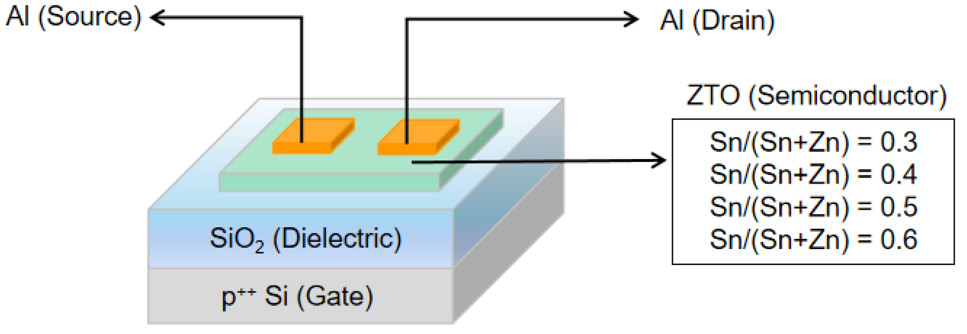
Figure 1. Illustration of structure of ZTO TFTs fabricated in this study. The Sn/(Sn+Zn) ratio is controlled from 0.3 to 0.6 in ZTO semiconductors.
Coatings 12 01534 g001
Figure 2. XPS O 1s spectra for ZTO semiconductors with Sn/(Sn+Zn) ratios of (a) 0.3, (b) 0.4, (c) 0.5, and (d) 0.6.
Coatings 12 01534 g002
Figure 3. AFM images of ZTO semiconductor surface with Sn/(Sn+Zn) ratios of (a) 0.3, (b) 0.4, (c) 0.5, and (d) 0.6.
Coatings 12 01534 g003
Figure 4. Transfer characteristics of ZTO TFTs with Sn/(Sn+Zn) ratios of (a) 0.3, (b) 0.4, (c) 0.5, and (d) 0.6. Black and red lines indicate transfer characteristics with forward and backward sweep, respectively. The detailed plot of Sn/(Sn+Zn) ration regarding (e) mobility, (f) threshold voltage, (g) subthreshold swing, and (h) hysteresis.
Coatings 12 01534 g004
Figure 5. Transfer characteristics of ZTO TFTs with Sn/(Sn+Zn) ratios of (a) 0.3, (b) 0.4, (c) 0.5, and (d) 0.6 under PBS for specific stress times.
Coatings 12 01534 g005
Figure 6. Transfer characteristics of ZTO TFTs with Sn/(Sn+Zn) ratios of (a) 0.3, (b) 0.4, (c) 0.5, and (d) 0.6 under NBS for stress time.
Coatings 12 01534 g006
Publisher’s Note: MDPI stays neutral with regard to jurisdictional claims in published maps and institutional affiliations.