Article

Computation of Gamma Buildup Factors and Heavy Ions Penetrating Depths in Clay Composite Materials Using Phy-X/PSD, EXABCal and SRIM Codes

1
Department of Physics and Engineering Physics, Obafemi Awolowo University, Ile-Ife 220282, Nigeria
2
Department of Physics, Faculty of Science, Isra University, Amman 11622, Jordan
3
Department of Nuclear Medicine Research, Institute for Research and Medical Consultations (IRMC), Imam Abdulrahman Bin Faisal University (IAU), Dammam 31441, Saudi Arabia
4
Department of Physics, Osun State University, Osogbo 210001, Nigeria
5
Department of Physics, College Science, Princess Nourah Bint Abdulrahman University, P.O. Box 84428, Riyadh 11671, Saudi Arabia
6
Centre for Energy Research and Development (CERD), Obafemi Awolowo University, Ile-Ife 220282, Nigeria
*
Authors to whom correspondence should be addressed.
Coatings 2022, 12(10), 1512; https://doi.org/10.3390/coatings12101512
Submission received: 9 August 2022 / Revised: 26 September 2022 / Accepted: 6 October 2022 / Published: 10 October 2022
(This article belongs to the Section Thin Films)

Abstract

:
Most investigations of the gamma-shielding abilities of materials are often based on the Beer-Lambert law including recent studies on clay-polyethylene composites. The findings are usually silent on the secondary radiation effects that commonly occur due to photon buildup, known as Energy Absorption Buildup Factor (EABF) and Exposure Buildup Factor (EBF). In this work, the computation of EABF and EBF in the region of energy 0.015–15 MeV at different penetration depths or mean free paths up to 40 mfp—and simulation of 100 keV of Cs and Sr ion-penetration profiles of clay–polyethylene composites (A–G) containing 0–30 wt% low density polyethylene (LPDE)—was carried out. The buildup factors computation was performed using Phy-X/PSD and EXABCal codes, and the ion-penetrating profile was studied using a Monte Carlo simulation code called Stopping and Range of Ions in Matter (SRIM). The EABF and EBF values are functions of the photon energy and the penetration depth. In the region of intermediate energy, the EABF and EBF values are higher for each of the samples. For a given mfp, the peak value of either EBF or EABF of each sample increases with LDPE wt% in the clay matrix. The projected range of both Cs and Sr ions in the samples decreased with increasing sample bulk densities, with Cs having a higher projected range than Sr in all the samples. The Cs and Sr ions have the lowest respective projected ranges in sample A (of bulk density 2.03 g·cm−3; 0 wt% of LDPE), while the highest projected ranges were recorded in sample G (of bulk density 1.34 g·cm−3; with 30 wt% of LDPE), respectively. This study reaffirmed the suitability of clay composite for gamma-ray shielding applications; however, it may not yet be ready to be used as a backfill material to mitigate the migration of fission products present in radioactive nuclear wastes.

1. Introduction

A low carbon-based energy economy development is one of the global priorities. There are no arguments that nuclear power is an efficient low-carbon energy source. Apart from being a virile source of clean energy, nuclear technology’s usefulness has spread across many fields. This has made its benefits to humanity more obvious in recent times than ever before.
Despite various benefits of nuclear technology, the protection of people from the inevitable emitting ionizing radiations as well as containment of nuclear waste are some of the major concerns in nuclear applications. Studies have proven beyond doubt the harmful effects of ionizing radiations on humanity and the devastating socio-economic impact of the release of radiological materials to the urban environment.
Earlier studies on the gamma shielding abilities of clay showed the possibility of application of clay composites for gamma radiation shielding [1,2]. Nevertheless, these studies and most studies on other materials are based on the Beer–Lambert law [3,4];
I = I o e μ x .
The law is based on three assumptions: narrow beam geometry, thin absorbing material and monochromatic rays, and any deviation requires the modification of Equation (1). This modified equation is written as [5];
I = B I o e μ x
where B stands for the buildup factors, namely Energy Absorption Buildup Factor (EABF) and Exposure Buildup Factor (EBF). The modification accounts for the secondary radiation effect that commonly occurs because of photon buildup from incident beam collision [6].
Furthermore, the performance of a material exposed to high radiation environments is a function of energy transfer from energetic heavy ions to the material. The localized electronic excitations, charging of pre-existing defects and rupture of chemical bonds due to the electron-hole pair production, and enhancing defect as well as atomic diffusions due to inelastic energy converts to the electrons (free or bound) are known as the loss of electronic energy. Usually, the total stopping power S of a material is the loss of energy (E) per unit path length traveling in the material of an ion and equal to the sum of both electronic stopping (inelastic energy loss) and nuclear stopping (elastic energy loss). Studies have shown that nuclear stopping power and electronic stopping power are dominant at high energy and low energy regions, respectively [7,8].
In this study, the EBF and EABF of clay composite materials were determined using Phy-X/PSD and EXABCal software, while the range, electronic and nuclear energy losses, and vacancy files of 137Cs and 90Sr ions (common nuclear waste fission products) were evaluated using the SRIM code. This study aimed to give more insight about the gamma radiation shielding capability (GRSC) of the clay composites materials and to provide information on possible application of the material for nuclear waste containment.

2. Materials and Methods

Olukotun et al. [9,10,11] reported details about the fabrication, elemental compositions, bulk densities and other properties of the clay–polyethylene composite materials (sample A–G) used in this work. The buildup factors computation was performed using Phy-X/PSD and EXABCal codes. The computational method, the capability and how to use the codes have been described in detail by Olarinoye et al. [12] and Şakar et al. [13]. In brief, the two codes used the Geometric Progress (G-P) fitting method to compute buildup factors for the photon energy range 0.015–15 MeV up to a penetration depth of 40 mfp. The computation is divided into three steps as mentioned elsewhere [14].
A Monte Carlo simulation code SRIM in full damage cascade mode was used to simulate Cs and Sr interaction with the clay samples (of different elemental compositions and substrate densities). Estimated energy of 100 keV was inputted in the SRIM program (version 2013) for each calculation. This energy would correspond to about 0.2 dpa for recoiling nuclei in the clay matrix [15]. The SRIM recommended displacement energies (for the elemental compositions of the clay materials) were assumed in the calculation. Ziegler et al. [16] gives details about SRIM code.

3. Results and Discussions

3.1. Variation of EBF and EABF with Incident Gamma Energy

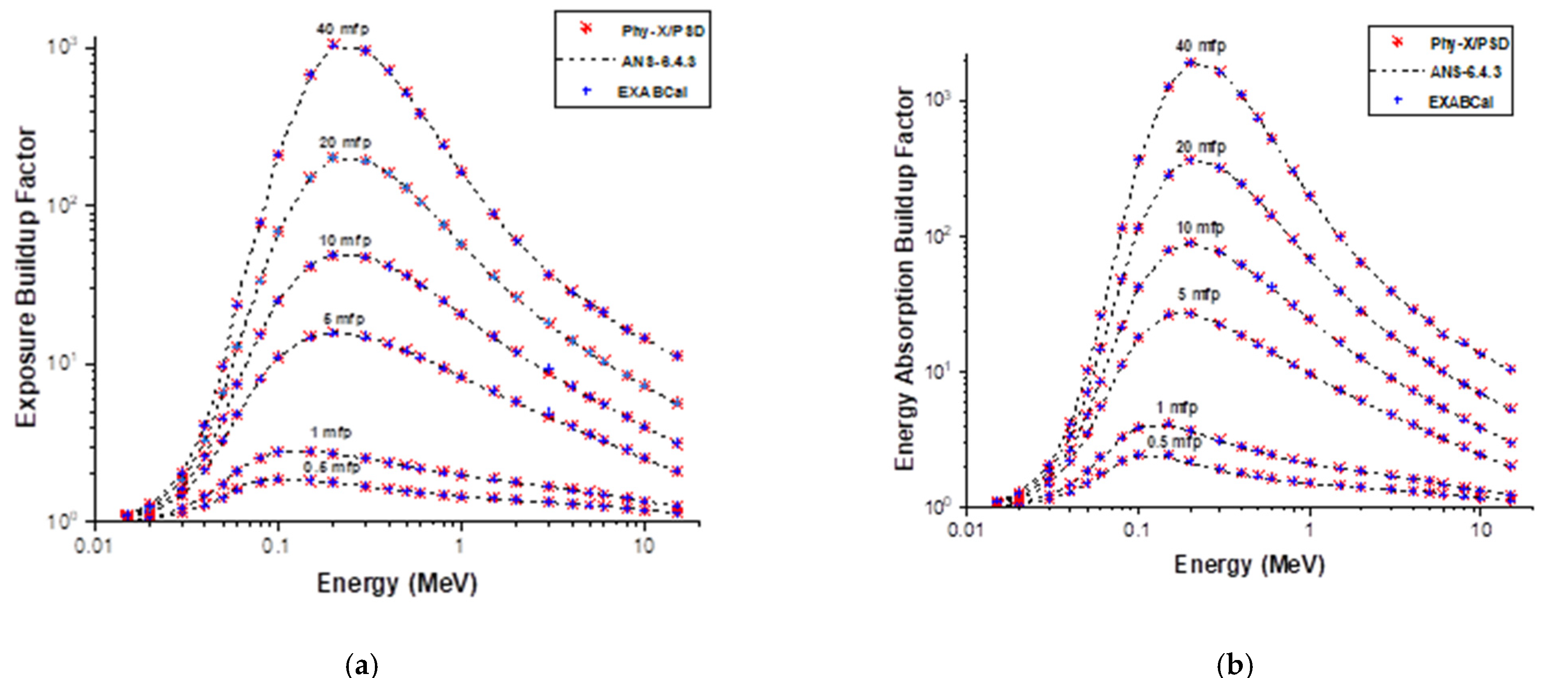
The Phy-X/PSD and EXABCal codes were first utilized to evaluate the EABF and EBF of water and concrete in the same energy range referred to in Section 2 and compared with standard data [17] to validate the obtained results. The compared variations of EBF and EABF with incident gamma energy were shown in Figure 1 and Figure 2, respectively. The results accord with the stardard data results; this ascertained the correctness of the calculations for the samples.
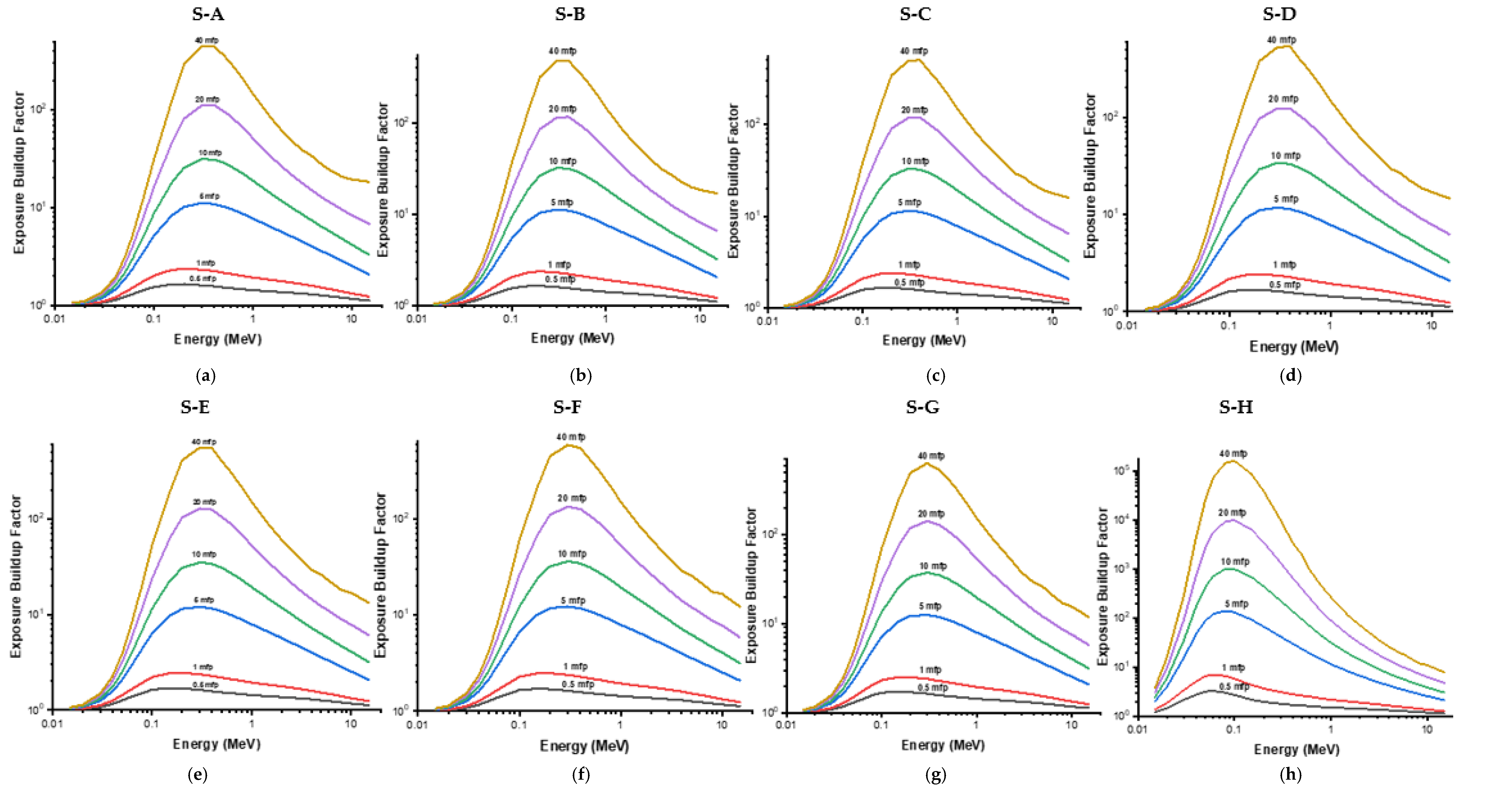
The EABF and EBF variations with the range of photon energy 0.015–15 MeV for each sample (A–H) at different penetration depths are shown in Figure 3 and Figure 4, respectively. These results showed that the obtained value increased as the energy of the photon increased for the discussed samples. For each sample, the increment continued until intermediate energies with maximum values, then started decreasing. This follows the same trend with reports of other materials given by some researchers such as Singh and Badiger [18,19]; Bursalıoğlu et al. [20]; Sayyed et al. [21]; Obaid et al. [22]. This is due to the photoelectric effect, Compton scattering and pair production photon interactions that are dominant at low, intermediate and high energy regions, respectively. For either photoelectric effect or pair production, a higher number of gamma photons are absorbed and therefore, EABF and EBF values are decreased. The degradation of photon energy, mainly by scattering without complete removal of the photon, is dominant with Compton scattering, hence the values of both factors are invariably high. In addition, increasing the depth of material penetration increases the thickness of the reactant. This increase in scattering occurs in the interacting medium, resulting in an increment in both the values of EABF and EBF as mfp value increases.
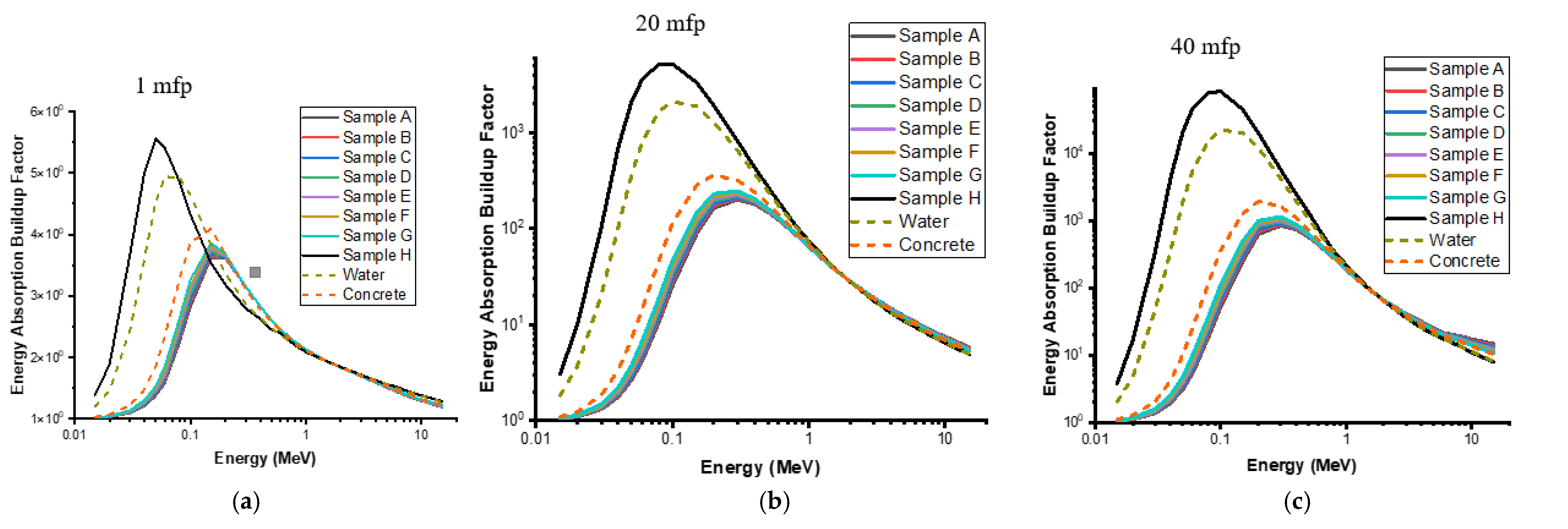
Figure 5 and Figure 6 give the results of EABF and EBF of the discussed samples compared with water and concrete for 0.015–15 MeV at 1, 20 and 40 mfp, respectively. At a given mfp, the highest peak value of both factors of the samples increases with LDPE wt% in the clay matrix. At the 1, 20 and 40 mfp, the peak results of EBF and EABF of the samples are lower than that of water and concrete, while that of H (recycled LDPE) is the highest. This is in line with the effects of LDPE on the other gamma shielding parameters, as reported by Olukotun et al. [9].

3.2. SRIM Simulation Results

The results obtained for each SRIM simulation include range, electronic and nuclear energy losses, and vacancy files. If clay is suggested as a containment material, it will continuously be exposed to different irradiations from nuclei decays, including Sr and Cs. To mimic the exposure of the clay materials to Sr and Cs, the SRIM program was used to simulate the distribution of Sr and Cs in the polyatomic clay target, as it was in an ion implantation study. The projected range and straggling were used to monitor the ion distribution in the clay samples. The clay sample with the lowest projected range is considered more suitable as a containment material than the one with high projected range. Figure 7a,b show the range profiles of Cs and Sr interactions with the clay samples A–G. Accordingly, each profile can be described as a normal distribution since the skewness(γ) and kurtosis (β) values (given in Table 1) are closer to that of an ideal Gaussian distribution (the skewness, γ = 0 and kurtosis, β = 3.0). For easy comparison, the projected range(s) and straggling of Cs and Sr ions were plotted against the sample bulk densities, as shown in Figure 8. The projected range of both ion types (in the samples A–G) decreases with increasing sample bulk densities. Compared with the corresponding Sr interaction with the clay samples, Cs has the highest projected range(s) in all the samples. One would expect Cs (a massive element) to have a lesser projected range than Sr. The larger projected range of Cs could have resulted from the complexity of the interaction of heavier projectiles with a multi-elemental target. However, the Cs and Sr ions have the lowest projected ranges of 66.5 nm and 80.8 nm recorded in sample A (of bulk density 2.03 g·cm−3), respectively, as shown in Figure 2. In contrast, Cs and Sr have the highest projected ranges of 96.6 nm and 117.2 nm in sample type G (of bulk density1.34 g·cm−3), respectively. It is important to recall that sample A is pure clay while samples B–G are modified clay samples with 0–30 wt% low density polyethylene (LPDE). It is clear from the above that the effect of LPDE on the clay samples influences the average penetration depths of these two important radiological fission surrogates (i.e., Cs and Sr). It can also be seen in Table 1 that the projected range straggling follows a similar trend as the projected range. This observation would also point to the difference in the microstructure of the samples. It has been reported by Olukotun et al. [11] that the introduction of LPDE into the clay samples reduces the crystallinity of the substrates. The implication of these projected range calculations is that pure clay has a high potential recommendation for use as a diffusion barrier (against radioactive Cs and Sr) compared to LPDE samples.
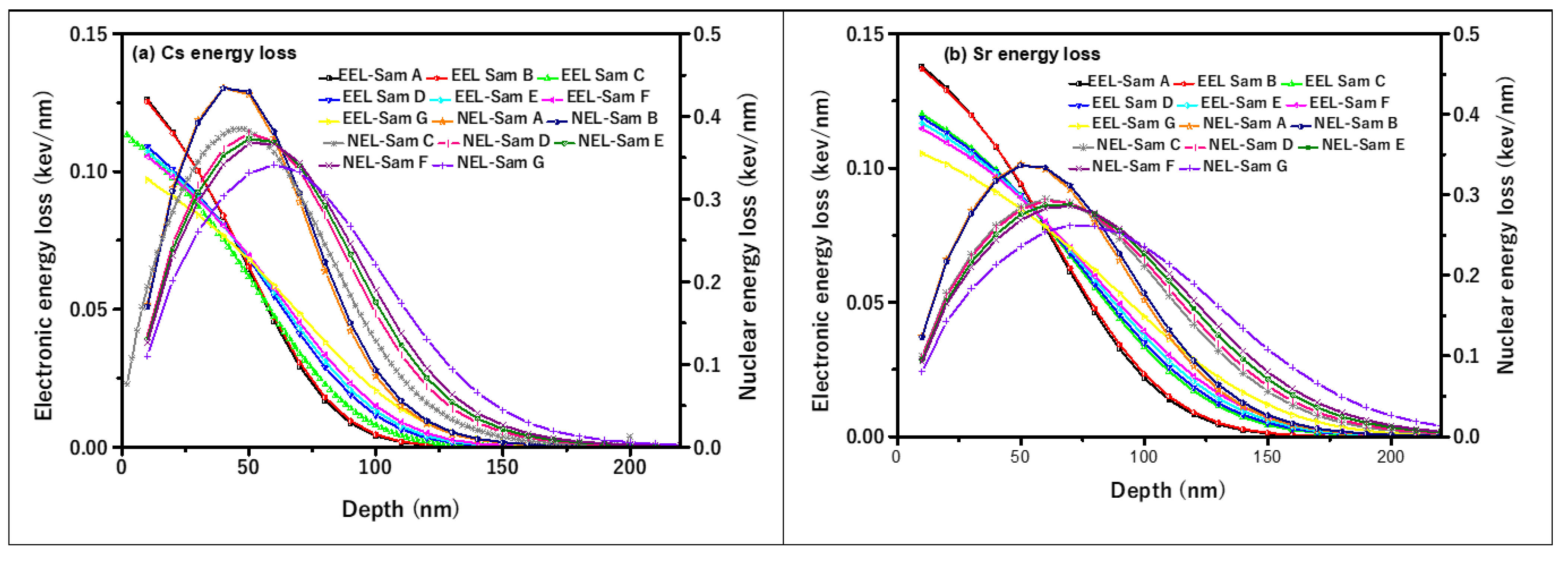
Figure 9 shows the energy loss (keV/nm) of Cs and Sr ions in different clay samples. The electronic energy loss ranged from 0.11 to 0.13 keV (for Cs), 0.11 to 0.14 keV/nm (for Sr) and the nuclear energy loss ranged from 0.34 to 0.43 keV/nm (for Cs) and 0.26 to 0.34 keV/nm (for Sr). The electronic energy loss is dominant from the surface to a maximum depth of about 40 nm. This implies that the damage created in the samples’ structures within the 0 to 40 nm range is mainly due to the electronic energy loss. The nuclear energy loss dominates from 40 nm to about 145 nm. It is clear from Figure 9 that nuclear energy loss is responsible for most of the damage (dpa) in the samples. The predominant damage to the clay samples can be attributed to the low irradiation energy (100 keV) of the Cs and Sr ions. To evaluate the amount of damage in the samples, the vacancies per ion per angstrom was converted to displacement per atom (dpa) using Equation (3) [23]:
dpa = ( V a c i o n ( Å ) × 10 8 ) × φ ( i o n c m 2 ) ρ G C ( a t o m s c m 3 )
V a c i o n ( Å ) is the vacancy per ion (Angstrom), 108 is a conversion parameter from Angstrom (Å) to a centimeter (cm), φ is the Cs or Sr ion fluence (which has been assumed to be 1 × 10¹⁴ ions/cm2), and ρGC is the density of the clay samples, as given in Table 1.
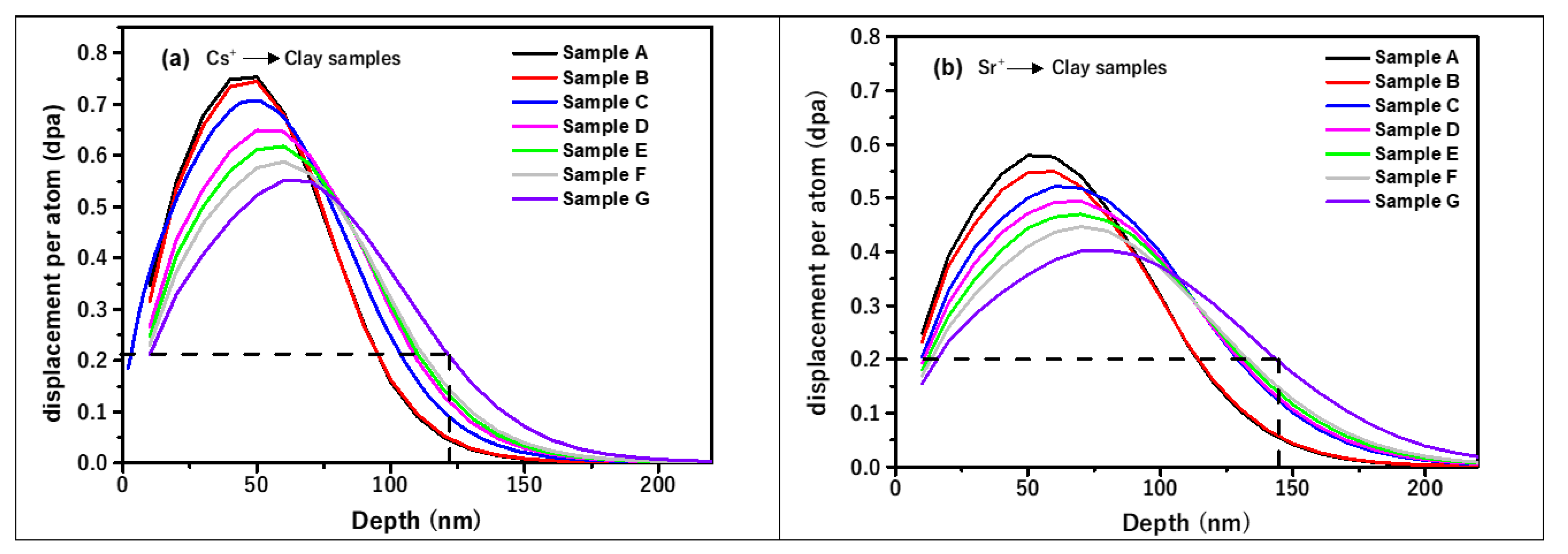
The peak of each displacement per atom (dpa) curve shown in Figure 10 represents the maximum dpa, where the bulk of the damage is in the samples. With about 0.2 maximum critical amorphizationdpa of clay materials [24,25], Cs and Sr completely amorphized all the clay samples A–G. Sample G will be more damaged upon Cs and Sr interaction than samples A–F. As stated above, the introduction of LPDE into the clay samples reduces its crystallinity, and the interaction of Cs and Sr ions with the (LPDE-improved) clay samples will further enhance the loss of long-range order of the clay sample matrix. Using the critical dpa of clay materials as a benchmark to compare the damage caused to the clay samples (by the two ion types), it is clear from Figure 10 that Cs would amorphize the clay matrix of samples A and G up to depths of 96 nm and 122 nm, respectively, while the induced damage caused by Sr in samples A and G is at a maximum depth of 116 nm and 145 nm, respectively. The difference in the magnitude of damage can be related to the smaller atomic mass of Sr than Cs; Sr is therefore expected to cause more damage to the clay samples than Cs. The complexity of the interaction of Cs and Sr projectile ions with multi-elemental target samples (such as clay) is another reason to account for the differences in the damage profiles.

4. Conclusions

The computation of EABF and EBF at different penetration depths up to 40 mfp and simulation of 100 keV of Cs and Sr ions penetration profile of clay–polyethylene composites, were successfully carried out using Phy-X/PSD, EXABCal codes and a Monte Carlo simulation code called SRIM. The clay–polyethylene composite materials (A–G) contained 0–30 wt% low density polyethylene (LPDE). In the intermediate energy region, they have maximum values. This is because at intermediate photon energy, mainly scattering without complete removal of the photon is dominant with Compton scattering, therefore the values of both EABF and EBF are invariably high. In addition, it was found that the values of EABF and EBF increased as the mean free path value (mfp) increases. This is because the increment in the depth of material penetration increased the thickness of the reactant which caused more scattering to occur in the interacting medium, giving an increment in the values of both EABF and EBF as mfp value increased. The trend of these findings is the same with reports of other researchers on different materials. The obtained results reaffirmed the suitability of the clay composite for photon shielding applications.
Furthermore, the simulated penetration profiles of Cs and Sr ions revealed that the projected range of both Cs and Sr ions in the samples decreased as the samples’ bulk densities increased. The Cs ion has a higher projected range than the Sr ion in all the samples. The Cs and Sr ions have the lowest projected ranges of 66.5 nm and 80.8 nm in sample A (of bulk density 2.03 g·cm−3; 0 wt% of LDPE), respectively, while the highest projected ranges of 96.6 nm and 117.2 nm were recorded in sample G (of bulk density 1.34 g·cm−3; with 30 wt% of LDPE), respectively.
The obtained EABF and EBF results reaffirmed the suitability of the clay composite for photon-shielding applications. It is worth pointing out that the gamma shielding efficiency of the clay–polyethylene decreased with the increment in wt% of LDPE in the clay matrix. Hence, sample A containing 0 wt% of LDPE is the most efficient, while sample G containing 30 wt% of LDPE is least efficient in gamma shielding. This fact is supported by the density trend of the composites; sample A has the highest bulk density of 2.03 g·cm−3 while sample G has the lowest, at 1.34 g·cm−3. However, the obtained Cs and Sr depth penetration profile revealed that the clay–polyethylene composites need to be further improved before it can be used as a backfill material to mitigate the migration of fission products present in radioactive nuclear wastes.

Author Contributions

Data curation, S.F.O., E.O.A., S.T.G. and M.K.F.; Formal analysis, S.F.O. and E.O.A.; Funding acquisition, N.A.; Investigation, M.I.S.; Methodology, O.F.O., S.T.G. and M.K.F.; Writing—original draft, M.I.S. and S.A.A.; Writing—review & editing, O.F.O., N.A. and S.A.A. All authors have read and agreed to the published version of the manuscript.

Funding

The authors express their gratitude to Princess Nourah bint Abdulrahman University Researchers Supporting Project number (PNURSP2022R111), Princess Nourah bint Abdulrahman University, Riyadh, Saudi Arabia.

Institutional Review Board Statement

Not applicable.

Informed Consent Statement

Not applicable.

Data Availability Statement

The authors confirm that the data supporting the findings of this study are available within the article.

Acknowledgments

The authors express their gratitude to Princess Nourah bint Abdulrahman University Researchers Supporting Project number (PNURSP2022R111), Princess Nourah bint Abdulrahman University, Riyadh, Saudi Arabia.

Conflicts of Interest

The authors declare no conflict of interest.

References

  1. Olukotun, S.; Gbenu, S.; Ibitoye, F.; Oladejo, O.; Shittu, H.; Fasasi, M.; Balogun, F. Investigation of gamma radiation shielding capability of two clay materials. Nucl. Eng. Technol. 2018, 50, 957–962. [Google Scholar] [CrossRef]
  2. Tajudin, S.; Sabri, A.; Aziz, M.A.; Olukotun, S.; Ojo, B.; Fasasi, M. Feasibility of clay-shielding material for low-energy photons (Gamma/X). Nucl. Eng. Technol. 2019, 51, 1633–1637. [Google Scholar] [CrossRef]
  3. Fugaru, V.; Bercea, S.; Postolache, C.; Manea, S.; Moanta, A.; Petre, I.; Gheorghe, M. Gamma ray shielding properties of some concrete materials. Acta Phys. Pol. A 2015, 127, 1427–1429. [Google Scholar] [CrossRef]
  4. Sayyed, M.; Lakshminarayana, G.; Kityk, I.; Mahdi, M. Evaluation of shielding parameters for heavy metal fluoride based tellurite-rich glasses for gamma ray shielding applications. Radiat. Phys. Chem. 2017, 139, 33–39. [Google Scholar] [CrossRef]
  5. Sayyed, M.; Elhouichet, H. Variation of energy absorption and exposure buildup factors with incident photon energy and penetration depth for boro-tellurite (B2O3-TeO2) glasses. Radiat. Phys. Chem. 2017, 130, 335–342. [Google Scholar] [CrossRef]
  6. Sayyed, M.; Alzaatreh, M.; Dong, M.; Zaid, M.; Matori, K.; Tekin, H.O. A comprehensive study of the energy absorption and exposure buildup factors of different bricks for gamma-rays shielding. Results Phys. 2017, 7, 2528–2533. [Google Scholar] [CrossRef]
  7. Kavaz, E.; Tekin, H.; Agar, O.; Altunsoy, E.; Kilicoglu, O.; Kamislioglu, M.; Abuzaid, M.; Sayyed, M. The Mass stopping power/projected range and nuclear shielding behaviors of barium bismuth borate glasses and influence of cerium oxide. Ceram. Int. 2019, 45, 15348–15357. [Google Scholar] [CrossRef]
  8. Olarinoye, I. Variation of effective atomic numbers of some thermoluminescence and phantom materials with photon energies. Res. J. Chem. Sci. 2011, 1, 64–69. [Google Scholar]
  9. Olukotun, S.; Gbenu, S.; Oladejo, O.; Sayyed, M.; Tajudin, S.; Amosun, A.; Fadodun, O.; Fasasi, M. Investigation of gamma ray shielding capability of fabricated clay-polyethylene composites using EGS5, XCOM and Phy-X/PSD. Radiat. Phys. Chem. 2020, 177, 109079. [Google Scholar] [CrossRef]
  10. Olukotun, S.; Gbenu, S.; Oladejo, O.; Balogun, F.; Sayyed, M.; Tajudin, S.; Obiajunwa, E.; Fasasi, M. The effect of incorporated recycled low density polyethylene (LDPE) on the fast neutron shielding behaviour (FNSB) of clay matrix using MCNP and PHITS Monte Carlo codes. Radiat. Phys. Chem. 2021, 182, 109351. [Google Scholar] [CrossRef]
  11. Olukotun, S.F.; Gbenu, S.T.; Oyedotun, K.O.; Fasakin, O.; Sayyed, M.I.; Akindoyin, G.O.; Shittu, H.O.; Fasasi, M.K.; Khandaker, M.U.; Osman, H.; et al. Fabrication and characterization of clay-polyethylene composite opted for shielding of ionizing radiation. Crystals 2021, 11, 1068. [Google Scholar] [CrossRef]
  12. Olarinoye, I.; Odiaga, R.; Paul, S. EXABCal: A program for calculating photon exposure and energy absorption buildup factors. Heliyon 2019, 5, e02017. [Google Scholar] [CrossRef] [PubMed] [Green Version]
  13. Şakar, E.; Özpolat, Ö.F.; Alım, B.; Sayyed, M.; Kurudirek, M. Phy-X/PSD: Development of a user friendly online software for calculation of parameters relevant to radiation shielding and dosimetry. Radiat. Phys. Chem. 2020, 166, 108496. [Google Scholar] [CrossRef]
  14. Harima, Y. An approximation of gamma-ray buildup factors by modified geometrical progression. Nucl. Sci. Eng. 1983, 83, 299–309. [Google Scholar] [CrossRef]
  15. Allard, T.; Calas, G. Radiation effects on clay mineral properties. Appl. Clay Sci. 2009, 43, 143–149. [Google Scholar] [CrossRef]
  16. Ziegler, J.F.; Ziegler, M.D.; Biersack, J.P. SRIM—The stopping and range of ions in matter. Nucl. Instrum. Methods B 2010, 268, 1818–1823. [Google Scholar] [CrossRef] [Green Version]
  17. ANSI/ANS-6.4.3; Gamma Ray Attenuation Coefficient and Buildup Factors for Engineering Materials. American Nuclear Society: La Grange Park, IL, USA, 1991.
  18. Singh, V.; Badiger, N. Gamma-ray exposure build-up factors of some brick materials in the state of Punjab. Radioprotection 2013, 48, 511–526. [Google Scholar] [CrossRef] [Green Version]
  19. Singh, V.P.; Badiger, N. Energy absorption buildup factors, exposure buildup factors and Kerma for optically stimulated luminescence materials and their tissue equivalence for radiation dosimetry. Radiat. Phys. Chem. 2014, 104, 61–67. [Google Scholar] [CrossRef]
  20. Bursalıoğlu, E.; Balkan, B.; Kavanoz, H.B.; Okutan, M.; Íçelli, O.; Yalçın, Z. Energy absorption and exposure buildup factors of essential amino acids. BioMed Res. Int. 2014, 2014, 359754. [Google Scholar] [CrossRef] [Green Version]
  21. Sayyed, M. Half value layer, mean free path and exposure buildup factor for tellurite glasses with different oxide compositions. J. Alloy. Compd. 2017, 695, 3191–3197. [Google Scholar] [CrossRef]
  22. Obaid, S.S.; Sayyed, M.; Gaikwad, D.; Pawar, P. Attenuation coefficients and exposure buildup factor of some rocks for gamma ray shielding applications. Radiat. Phys. Chem. 2018, 148, 86–94. [Google Scholar] [CrossRef]
  23. Hlatshwayo, T.; Sebitla, L.; Njoroge, E.; Mlambo, M.; Malherbe, J. Annealing effects on the migration of ion-implanted cadmium in glassy carbon. Nucl. Instrum. Methods Phys. Res. Sect. B Beam Interact. Mater. Atoms 2017, 395, 34–38. [Google Scholar] [CrossRef] [Green Version]
  24. Dran, J. Radiation effects in radioactive waste storage materials. Solid State Phenom. 1992, 30–31, 367–378. [Google Scholar] [CrossRef]
  25. Sorieul, S.; Allard, T.; Wang, L.M.; Grambin-Lapeyre, C.; Lian, J.; Calas, G.; Ewing, R.C. Radiation-stability of smectite. Environ. Sci. Technol. 2008, 42, 8407–8411. [Google Scholar] [CrossRef] [PubMed]
Figure 1. (a) EBF and (b) EABF of water obtained compared with those of the standard ANSI/ANS-6.4.3 at different mfp’s.
Coatings 12 01512 g001
Figure 2. (a) EBF and (b) EABF of concrete obtained compared with those of the standard ANSI/ANS-6.4.3 at different mfp’s.
Coatings 12 01512 g002
Figure 3. EBF of Sample A, B, C, D, E, F, G and H, respectively for range 0.015–15 MeV at different mfp’s. (a) is S-A, (b) is S-B, (c) is S-C, (d) is S-D, (e) is S-E, (f) is S-F, (g) is S-G and (h) is S-H.
Coatings 12 01512 g003
Figure 4. EABF of Sample A, B, C, D, E, F, G and H, respectively for range 0.015–15 MeV at different.(a) is S-A, (b) is S-B, (c) is S-C, (d) is S-D, (e) is S-E, (f) is S-F, (g) is S-G and (h) is S-H.
Coatings 12 01512 g004
Figure 5. EBF of the Samples compared with water and concrete for energy region 0.015–15 MeV at 1, 20 and 40 mfp, respectively. (a) is 1 mfp, (b) is 20 mfp and (c) is 40 mfp.
Coatings 12 01512 g005
Figure 6. EABF of the Samples compared with water and concrete for energy region 0.015–15 MeV at 1, 20 and 40 mfp, respectively. (a) is 1 mfp, (b) is 20 mfp and (c) is 40 mfp.
Coatings 12 01512 g006
Figure 7. Depth profile of (a) Cs and (b) Sr in different clay samples.
Coatings 12 01512 g007
Figure 8. Projected range of Cs and Sr ions as a function of the sample bulk density.
Coatings 12 01512 g008
Figure 9. Predicted energy loss of (a) Cs and (b) Sr ions in the different clay samples. For the understanding of legends in Figure 4a,b, EEL-Sam A: electronic energy loss in sample A; NEL: Nuclear energy loss in sample A, etc.
Coatings 12 01512 g009
Figure 10. Displacement per atom (dpa) profile of (a) Cs and (b) Sr ions in different clay samples.
Coatings 12 01512 g010
Table 1. Simulation result of the four moments of Cs and Sr ions distribution in different clay samples.
IonSampleDensity
(g·cm−3)
Projected Range
(nm)
Projected Range Straggling (nm)Skewness
(γ)
Kurtosis
(β)
S-A2.03066.521.00.403.06
S-B1.97567.921.20.403.08
S-C1.68878.824.50.383.00
SrS-D1.63381.125.00.403.00
S-E1.56783.925.60.303.00
S-F1.50187.226.20.353.00
S-G1.34196.628.80.342.99
S-A2.03080.829.40.372.97
S-B1.97582.529.90.372.99
S-C1.68896.034.40.352.95
CsS-D1.63398.435.00.342.95
S-E1.567101.935.90.332.92
S-F1.501105.536.80.322.93
S-G1.341117.240.50.312.92
Publisher’s Note: MDPI stays neutral with regard to jurisdictional claims in published maps and institutional affiliations.