Abstract
Zinc-rich primers are among the most promising organic coating systems for improving the corrosion resistance of metals in the marine environment. However, the high zinc content results in poor coating adhesion, high cost, insecurity and pollution. To decrease the zinc dust content, the carbonaceous and polymer conductive additives carbon black (CB), conductive graphite (CG), multiwalled carbon nanotubes (MWCNT) and polyaniline (PANI) were introduced to partially replace the zinc dust in the primers. A comparative study of the anticorrosion performance of epoxy zinc-rich primer (ZRP) is presented herein to systematically discuss and elaborate on the effects of the different conductive additives. There were no blisters, rust or corrosion products presented on the coatings of the CB-modified series due to the good dispersion and conductivity of nanosized CB clusters, while the zinc corrosion products covered the surface of the MWCNT-modified series samples, which was attributed to the excessive electrical conductivity resulting in high consumption of zinc powder. The lamellar CG provided an additional blocking barrier for the coatings based on the maze effect. The transition from the intrinsic state to the doped state of PANI resulted in corrosion protection for the coatings depending on the cathodic and barrier function. The experimental results suggested that the formula with 2 wt.% CB and 67 wt.% zinc dust had the most promising anticorrosion properties, which was also demonstrated by the high Rct and low CPEdl values calculated according to the equivalent electrical circuit analyses.
1. Introduction
Offshore wind structures suffer from an extremely harsh and dynamic marine environment, which are mainly protected by coating systems. Sacrificial zinc-rich epoxy primers (ZRPs) that can provide effective cathodic protection due to the formation of galvanic cells between zinc dust and the steel substrate are widely used in the marine environment [1,2]. The zinc dust with a lower electrode potential is preferentially corroded as the sacrificial anode, thus protecting the cathode steel substrate [3].
The zinc content of traditional epoxy zinc primers is high, at approximately 80%, but the zinc utilization rate is not sufficient. This is because, with the oxidation of zinc dust, the generated zinc oxidation products hinder the galvanic effect so that the remaining zinc dust involved cannot provide cathodic protection [3]. In addition, epoxy zinc primers loaded heavily with zinc dust have poor coating adhesion and high cost, and cause environmental pollution [4]. The partial substitution of zinc dust with conductive additives is considered a productive approach for reducing the loading and improving the utilization of zinc dust. Incorporating conductive additives into epoxy zinc-rich primers will decrease the zinc dust loading without compromising the cathodic protection.
To reduce the loading, improve the utilization of zinc dust and prolong the service life of ZPR, the partial substitution of zinc dust with conductive additives is considered productive. In recent decades, the reliabilities of carbon black (CB) [5], conductive graphite (CG) [6,7], multiwalled carbon nanotubes (MWCNTs) [2] and polyaniline (PANI) [8] as conductive additives have been studied. There is a cross-link and a strong interfacial interaction between CB particles and coatings because of the large specific surface area. It was reported that the addition of 5 wt.% CB enhanced electrical conductivity inside a coating [3]. Lamellar conductive graphite (CG) is also an interesting nano-material representing a solution. MWCNTs are an attractive additive for the possible enhancement of electrical and thermal conductivities due to their large specific surface area and high aspect ratios [9]. The opinions of MWCNTs in different studies are opposing. Some research reported that, in the presence of MWCNTs, the percolation threshold could arrive, even at a low zinc concentration [9], while some works found that the micro-galvanic cells formed between the metal substrate and CNTs brought counter effects on the coating corrosion against performance [10]. Of particular interest is the applicability of the conducting polymer PANI for the anticorrosion protection of metals [8,11,12,13]. David DeBerry [14] reported that the corrosion resistance of metals was significantly improved by PANI deposition.
Owing to the conductivities of CB, CG, MWCNT and PANI, there have been several studies reporting that they can be used in zinc-rich primers to improve the conductivity of zinc dust, promote the anode sacrificial effect and improve the coating anti-corrosion performance. However, considering the differences in the conductivities and other physical and chemical properties of the four materials, little systematic research has been reported comparing these conductive additives in the corrosion resistance of epoxy zinc-rich primers. In this paper, the anticorrosion performances of these four additives and the possible anticorrosion mechanisms in the same coating system (ZRPS) were systematically analyzed based on the conductivity, structure and morphology of the conductive powders and the corrosion resistance of the coatings. Equivalent electrical circuit analyses of the optimal coating with 2 wt.% CB and 67 wt.% zinc dust were also presented.
2. Materials and Methods
2.1. Materials and Formulations
The original zinc-rich primer (80Zn) consisted of 80 wt.% zinc dust (purchased from Hunan New Wellink Advanced Metallic Material Co., Ltd., Changsha, China) and the remaining 20 wt.% was E44 epoxy resin (provided by Sanmu Group, Chengdu, China), pigment, filler and other auxiliaries. Based on 80Zn, a conductive additive was added to prepare the modified zinc-rich primers. Four different anti-corrosive conductive additives, i.e., carbon black (CB) (produced by Mitsubishi Group, Tokyo, Japan), conductive graphite (CG) (supplied by Qingdao Qinglin Shimo Graphite Co., Ltd., Qingdao, China), multiwalled carbon nanotubes (MWCNTs) (provided by Shanghai Yaotian New Material Technology Co., Ltd., Shanghai, China) and polyaniline (PANI) (Jin Gute Co., Ltd., Chongqing, China), were selected. The median size (D50: the particle diameter of which 50 vol.% of the particles are smaller) of the additives was measured using a laser particle size distribution instrument (BT2000B, Bettersize instruments Ltd., Dandong, China). The specific surface area and oil absorption of the additives provided by the suppliers are listed in Table 1. According to the suggestions of the suppliers and the literature [15,16], three different contents, 1 wt.%, 2 wt.% and 4 wt.%, were selected for the incorporation of additives.

Table 1.
Properties of the four different anti-corrosive conductive additives.
The metallic substrates were steel panels (purchased from Biuged Laboratory Instruments Co., Ltd., Guangzhou, China) and aluminum panels (purchased from Shenghua BEVS Co., Ltd., Guangzhou, China) with dimensions of 7 cm × 15 cm; the former were used for neutral salt spray tests and electrochemical measurements and the latter were prepared for coating morphology analysis.
2.2. Preparation of Paints and Coated Panels
The modified and original zinc-rich primers were prepared as follows. Firstly, the epoxy resins, pigment and auxiliaries were mixed and stirred at 1400 rpm for 1 h with appropriate amounts of glass beads using a high-shear mechanical mixer. Then, the glass beads were filtered, followed by the addition of zinc dust, and the mixture was continuously stirred for another 30 min to disperse the zinc powder. According to the types of conductive additives (CB, CG, MWCNTs and PANI) added in the first step, we named these paints XCB-YZn series, XCG-YZn series, XMWCNT-YZn series and XPANI-YZn series, respectively. X represents the dosage of the additives (wt.%, X = 1, 2 or 4) and Y represents the amount of zinc powder (wt.%, Y = 80 or 67), for instance, 2CB-67Zn means that the paint sample contained 2% carbon black and 67% zinc powder.
The paint and the corresponding curing agent were mixed in a certain proportion and then screened through 60-mesh gauze. The substrates were sandblasted and degreased by ethanol prior to spraying the coatings. Afterward, the coatings were obtained after curing at 70 °C for 30 min in a drying oven and cooling down to the ambient temperature. The average value of the dry film thickness at six points was measured using a PosiTector 6000 thickness gauge (DeFelsko, New York, NY, USA) and controlled at 75 μm for the neutral salt spray tests or 65 μm for the electrochemical measurements.
2.3. Characterization and Evaluation
2.3.1. Conductivity Tests of Powders
The electrical conductivity and compressing density of the powders were recorded using an ST2742B digital powder resistivity tester (Suzhou Jingge Electronic Co., Ltd., Suzhou, China) at room temperature. Three grams of the powder samples were pressed into a cylindrical mold with an area of 1 cm2 and the conductivity was continuously recorded as the pressing increased. The electrical conductivities adopted in this work were the data under 2 MPa, based on a modification of related investigations [17,18,19] and the manufacturer’s advice.
2.3.2. Raman Spectroscopy
The structure of the three carbonaceous powders and the defect states of carbon atoms were characterized by Raman spectroscopy (DXR Microscope, ThermoFisher Scientific, Waltham, MA, USA). The laser excitation was at 532 nm. The powders were tested on a glass sheet.
2.3.3. X-ray Photoelectron Spectroscopy (XPS)
X-ray photoelectron spectroscopy (XPS, ESCALAB 250 Xi, ThermoFisher Scientific, Waltham, MA, USA) with Al Kα radiation was used to confirm the surface elemental compositions and bonding configuration. The analytical pressure was lower than 10−8 Pa.
2.3.4. Morphology Analysis
A scanning electron microscope (SEM, Regulus 8100, HITACHI Ltd., Tokyo, Japan) was used to study the structures and surface morphology of four conductive powders. The scanning voltage was set to 3 kV and the working distance was 9 mm. The powders were dispersed on electroconductive paste and sputtered with gold before scanning. To study the morphology and elemental distribution of the surfaces and the fracture surfaces of these epoxy-based primers, the coated metal substrates were broken over liquid nitrogen.
2.3.5. Neutral Salt Spray Tests
Salt-spray chamber-type accelerated corrosion assays were conducted to simulate the corrosion of panels in an actual marine environment and instructed by ISO 9227:2017. Two intersecting scribes of 0.1 mm × 100 mm consisting of an “X” shape were generated on each coating for the test. The corrosion tests were carried out in a neutral spray cabinet (Shanghai Kece Experimental Instrument Co., Ltd., Shanghai, China) with 5 wt.% NaCl solution. The chamber temperature was set at 35 °C, and the temperature of the saturated pressure barrel was set at 47 °C and the pressure at 0.45 MPa. The mean overall width of delamination was calculated according to ISO 4628-8. The neutral salt spray test was carried out on the XCB-YZn, XCG-YZn, XPANI-YZn series and control sample (Zn80) for 500 h and XMWCNT-YZn for 200 h against photographed testing panels. Each sample had two duplicates.
2.3.6. Electrochemical Measurements
The glass-tube-fitted paint coating-covered metal steel panels, a saturated calomel electrode (SCE, 0.242 V vs. standard hydrogen electrode, SHE) and a platinum plate were used as the working, reference and counter electrodes, respectively. The electrochemical assessments were conducted on a 7 cm2 area of the coated panels by PARSTAT 2273 (AMETEK, Berwyn, PA, USA) and PowerSuite software 2.58 was used as the control system. The electrochemical cell was placed into a Faraday cage.
The open-circuit potentials (OCPs) and electrochemical impedance spectroscopy (EIS) were measured every 3–4 days and the first data points on Day 0 corresponded to the values of 20 min immersion. The OCP was produced by the galvanic behavior of zinc and iron and confirmed by SCE, which was used to determine the cathodic protection period of the zinc in the polymer in 3.5 wt.% NaCl solution. Then, electrochemical impedance spectroscopy (EIS) was recorded at OCP in the frequency range of 100 kHz to 10 MHz, applying a sinusoidal perturbation voltage of 10 mV. The impedance spectroscopy data were fitted by the most probable electrical circuits through the least-squares method using the software ZView version 4.0c.
3. Results and Discussion
3.1. Electrical Conductivity and Morphology of the Conductive Additives
Table 2 shows the reported isolated single-particle conductivity and the measured conductivity versus the pressure data of four additives. The isolated single particle conductivity data indicate the intrinsic material properties, and these conductive additives usually possessed giant intrinsic carrier mobilities due to their unique two-dimensional or three-dimensional structures. In the case of non-isolated particle investigations, it will be more meaningful to analyze the conductivity versus pressure data instead of the intrinsic conductivity due to the interface between the particles providing additional resistance to charge transfer, which is called the contact resistance effect. The effect was also demonstrated by the lower values of the conductivities at 2 MPa for the CB, CG and MWCNT as compared with the isolated single particle conductivity [20].
Table 2.
The conductivities of the four conductive additives.
The powder conductivities at 2 MPa of the carbonaceous powders were, in descending order, CG (12,400 S/m), MWCNT (743 S/m) and CB (252 S/m). A deeper understanding of the connection between the powder conductivities and the structures and states of the elements in the carbonaceous powders was obtained by Raman spectroscopy and X-ray photoelectron spectroscopy (XPS). Figure 1a shows the Raman spectra of the CB, CG and MWCNT powders. The D band located at 1350 cm−1 was related to defects, while the peak at 1580 cm−1, representing the G band, was related to the completely sp2-bonded carbon. The peak at 2700 cm−1 corresponded to the second order of the D band (2D) [24]. The D and G signals in the CB and MWCNT powders showed similar intensities, while CG powder had an almost negligible D band. The ratios of ID/IG (Raman intensity of the D band and G band) for CB, CG and MWCNT were calculated to be 1.36, 0.06 and 1.19, respectively. The value of ID/IG represents the density of defects, either caused by the loss of sp2 carbon or edge defects, in the carbon network [25]. The ID/IG ratio of CB was the largest, confirming that there were significant amounts of sp3 bonded carbon in CB that could bond with the epoxy resin and improve the interface reaction between the CB and the resin. The 2D signal only appeared in the CG and MWCNT powders, and the ratios of I2D/IG (Raman intensity of the 2D band and G band), regarded as the graphitization degree (C=C sp2 bond) [25], were calculated to be 1.42 and 0.73 for CG and MWCNT, respectively. To our surprise, the value of I2D/IG (1.42) for CG was close to that (I2D/IG = 2) of the single-layer defect-free graphene [26], indicating that there were few defects in CG powders.
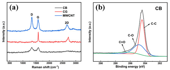
Figure 1.
(a) Raman spectra of three carbonaceous powders; (b) C 1 s XPS spectra of CB.
In view of the high value of ID/IG for the CB powder (1.36), XPS investigation into CB was further conducted to complement the Raman spectra and determine the bonding configuration. Figure 1b shows that the high-resolution C1s spectrum could be resolved into three peaks by deconvolution. The peak centered at 284.4 eV was ascribed to sp3-hybridized carbon, the peak at about 285.1 eV corresponded to C–O and the weak signal at about 286.8 eV indicated the C=O bond. The three peaks all agreed well with the C1s components of CB [27,28,29,30]. These oxygen-containing groups formed because of the binding of oxygen to incompletely bonded carbon atoms on carbon black during synthesis [30].
Based on the Raman spectroscopy and X-ray photoelectron spectroscopy (XPS) investigations, the lowest conductivity of CB was attributed to the mixture of sp3 and sp2 hybridized carbon atoms creating more defects [31], but it should be noted that the amorphous CB cluster size was no more than 100 nm (Figure 2a), which allowed uniform dispersal. The highest conductivity of CG was attributed to the 2–5 μm layered structure shown in Figure 2b and the sp2 hexagonal ring honeycomb slice observed in the previous research [32]. The conductivity mechanism of MWCNT was similar to that of CG, since the p orbital electrons of carbon atoms could also form a wide range of delocalized π bonds [33], and the compromised conductivity was related to the multi-pipe diameter and spiral angle of the pipe wall compared with the CG conductivity at 2 MPa and the isolated single-MWCNT-particle conductivity.
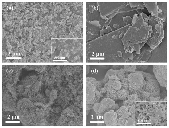
Figure 2.
SEM images of the four different conductive additives: (a) CB; (b) CG; (c) MWCNT; (d) PANI.
In addition to the three different types of carbonaceous powders, the conductivity at 2 MPa of conducting polymer (PANI) was 3.7 × 10⁻⁸ S/m. The conductivity value of PANI was lower than that of the carbonaceous powders, which was related to the intrinsic properties of polyaniline. Figure 2d shows that the PANI powders had a unique dendrite-like structure, which has been revealed to possess corrosion-protection performance, according to previous research [34].
3.2. Surface Morphology and Element Distribution of Coating Samples
The spherical zinc powder could be observed on the Zn80’s surface through scanning electron microscopy (SEM). The CB-Zn series and CG-Zn series samples (Figure 3c–h) showed distinct surface morphologies composed of zinc particles with a size of 10 μm and corresponding conductive additives, in line with the CB clusters and CG flakes presented in Figure 2a,b, respectively. Owing to the nanoscale of the carbon nanotubes, the magnifications of the MWCNT-Zn series were increased to 20 K. The incorporation of MWCNT and content-increasing tendency are shown clearly in Figure 3i–k. The surfaces of the PANI series were similar to those of the Zn80 surface.
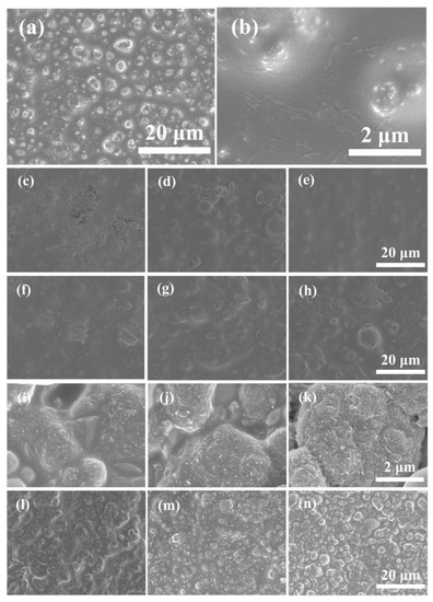
Figure 3.
SEM images of the unmodified and modified sample surfaces: (a,b) 80Zn; (c) 1CB-80Zn; (d) 2CB-67Zn; (e) 4CB-67Zn; (f) 1CG-80Zn; (g) 2CG-67Zn; (h) 4CG-67Zn; (i) 1MWCNT-80Zn; (j) 2MWCNT-67Zn; (k) 4MWCNT-67Zn; (l) 1PANI-80Zn; (m) 2PANI-67Zn; (n) 4PANI-67Zn.
The SEM images of the sample cross-sections supplement the film structure. Four typical samples incorporated with 2 wt.% additives are presented owing to the similarity of each series of samples. The cross-section of Zn80 was rough and composed of a number of round zinc particles. The CB-modified series exhibited different cross sections from Zn80, and the small clusters presented were associated with the additional content of CB. The uniform and dense dispersal of carbon black particles in 2CB-67Zn will provide great potential for the connections of zinc particles. The lamellar structure of CG can be observed in Figure 4c, and the porosities indicate that coating of 2CG-67Zn was not dense enough. The tip structures of MWCNT embedding inside the coating are evident. The clusters shown in Figure 4e are in accordance with the dendritic-like structure of PANI powders.
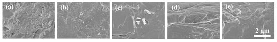
Figure 4.
Cross-sections of unmodified and modified samples: (a) 80Zn; (b) 2CB-67Zn; (c) 2CG-67Zn; (d) 2MWCNT-67Zn; (e) 2PANI-67Zn.
The energy dispersive X-ray spectroscopy (EDX) mapping tests were only carried out in the control sample and 2PANI-67Zn was limited by the existence of carbon elements in both carbonaceous powders and the epoxy resin. The aggregation of Zn signals can be observed in Figure 5a, showing that the distribution of the Zn element is not uniform in 80Zn coating. While the 2PANI-67Zn sample exhibits a more uniform Zn signal and the well-dispersed and enhanced nitrogen signals approve the complete incorporation of PANI.
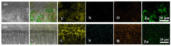
Figure 5.
EDX mapping results of (a) 80Zn and (b) 2PANI-67Zn.
3.3. Effect of Conductive Additives on the Anti-Corrosion Performance of Coating Samples
Based on the prominent conductivities of the additives and the rough surface morphology of the modified samples, we further studied the effect of the conductive additives on the anti-corrosion performance. The accelerated corrosion assay results (Figure 6b–d,l) show that the delamination and corrosion around the scribe of all of the CB-modified samples and 2PANI-67Zn were in grade 1 (very slight), and the mean overall width of the delamination was less than 0.8 mm according to ISO 4828-8, showing even better corrosion resistance than that of the control sample, Zn80 (grade 2, slight, width = 1.0 mm). There was slight corrosion (grade 2) throughout the inscribed area after 500 h of exposure to the ambient salt spray for the CG- and PANI-modified samples. For the MWNCT series, the zinc dust was largely consumed to produce a number of white corrosion products after only 200 h of the salt spray test; thus, the corrosion widths of the MWNCT series were not measured. To better confirm the corrosion products of the MWCNT-modified coatings after the salt spray test, Raman spectroscopic investigation was conducted. As shown in Figure 6n, the peaks at 259.03 and 389.51 cm−1, which correspond to the Zn–Cl stretching vibration and Zn–O stretching, respectively, were both identified as the characteristic peaks of ZnCl2·4Zn(OH)2·H2O. Additionally, the peak of 1069.69 cm−1 was attributed to the resin component of the coating [35,36].
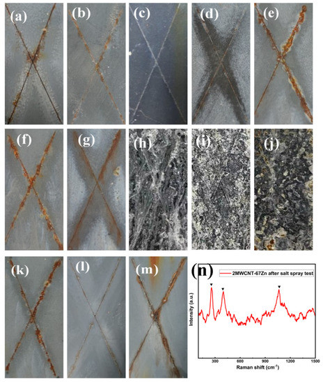
Figure 6.
Salt spray test results: (a) 80Zn; (b) 1CB-80Zn; (c) 2CB-67Zn; (d) 4CB-67Zn; (e) 1CG-80Zn; (f) 2CG-67Zn; (g) 4CG-67Zn; (h) 1MWCNT-80Zn; (i) 2MWCNT-67Zn; (j) 4MWCNT-67Zn; (k) 1PANI-80Zn; (l) 2PANI-67Zn; (m) 4PANI-67Zn; (n) Raman spectrum of the zinc corrosion products of 2MWCNT-67Zn after salt spray test.
Together with the type of additives, the conductive additive concentration has also been proven to have a great influence on the anti-corrosion performance. Each additive had its own optimum content. 2CB-67Zn was considered the best among the CB-modified series based on the narrowest creepage (about 0.4 mm) and the absence of rust spots or blisters, and the same additive dosage was also applicable for the PANI series, suggesting that an additive content of 2 wt.% may be optimal for CB and PANI series. On one hand, the results indicate that the zinc dust content of the ZRP can be reduced from 80% to 67% by partially substituting the zinc dust with conductive particles without compromising the corrosion resistance efficiency of the ZRPs. H. Marchebois et al. [3] revealed similar results, that there are optimal formulations for CB-modified zinc-rich primers, by studying powder coatings. Real cathodic protection can only be established when sufficient CB was added to the zinc-rich powder paints with 50 wt.% zinc dust content. However, it seems that the three additive loadings of the CG and MWCNT series (Figure 6e–j) are not suitable, based on the presence of severe corrosion and zinc corrosion products, and 1CG-80Zn (Figure 6e) showed the widest creepage (about 1.7 mm). However, Ewa Langer et al. [37] performed experiments on a series of coatings with 35 wt.% Zn pigments and 0.6 wt.% carbon nanotubes (CNTs) and revealed that the coatings showed good corrosion resistance after a 1500 h salt spray test, as well as superior physical and mechanical properties. Based on the combination of Ewa Langer et al. and our findings, it seems that the addition amount of MWCNT should be reduced. Excessive addition of MWCNT will cause the extraordinary connection of zinc dust while also causing the consumption of a large amount of zinc dust.
The overall shielding function and cathodic protection mechanism offered by the zinc-rich primers incorporated with conductive additives were further explored by investigating the electrochemical measurements recorded using the open circuit potential (OCP) and electrochemical impedance spectroscopy (EIS) techniques.
Epoxy zinc-rich coatings can provide cathodic protection when the OCP value is less than −0.80 V, according to previous studies [3]. As can be seen in Figure 7, the OCP value of the control sample Zn80 was always positive than −0.80 V (vs. SCE), while the EIS value was kept within an order of 109 magnitude during the testing period, indicating that the control sample could provide a significant barrier effect. The rapid consumption of zinc dust produced a large amount of zinc corrosion products to provide a barrier. The prominent cathodic protection of CB-modified coatings was considered to remain, based on the OCP values of 1CB-Zn80, 2CB-Zn67 and 4CB-Zn67, which were all kept below −0.80 V during the period of testing. The results are in accordance with the salt-spray test results that CB was efficient in conducting zinc dust. The potentials of 1CG-Zn67 and 2CG-Zn67 were more negative than −0.80 V for 13 days, except for that of 4CG-67Zn, which increased above the protection level on the fourth day, corresponding to the poor corrosion performance against 500 h in the salt spray test. To our surprise, the OCP values of the MWCNT-modified series remained more negative than −0.80 V; however, the appearance of corrosion products in the salt spray results showed that all MWCNT-modified samples were seriously corroded. This suggests that the excessive promotion of the galvanic action of zinc and the substrate with MWCNTs caused high consumption of zinc dust and coating failure.
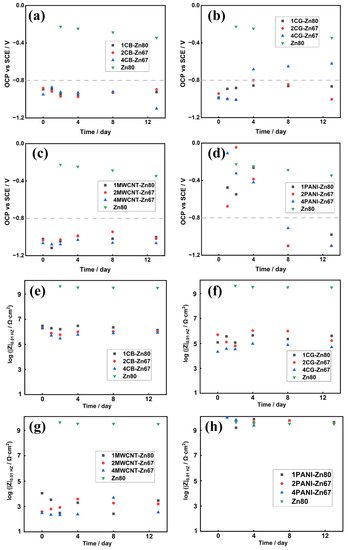
Figure 7.
OCP and Rp values of XCB-YZn series (a,e), XCG-YZn series (b,f), XMWCNT-YZn series (c,g) and XPANI-YZn series (d,h).
The OCP values of 1PANI-Zn80, 2PANI-Zn67 and 4PANI-Zn67 were above the protection level for the first 4 days and then fell below −0.80 V after 8 days of salt solution immersion. According to the |Z|0.01HZ values of the modified and unmodified coatings shown in Figure 7, the|Z|0.01HZ values of the PANI-modified samples are kept within the order of 1010 magnitude and were the highest among the four types of modified samples, and even an order of magnitude higher than that of the control. The electrochemical test results indicate that, in contrast to the single cathodic protection provided by a coating with a carbonaceous-based conductive agent, there was a combined anticorrosion effect dominated by the shielding effect during the early stage and cathodic protection during the later stage for the case of conducting polymers. These results are similar to the corrosion behavior of ZRPs with conductive polyaniline-grafted graphene (PANI/Gr) reported by Yanhua Lei et al., which exhibited a synergetic effect of the physical barrier, and the cathodic protection was observed with the ZRP sample containing 80% zinc dust and 0.4 wt.% PANI/Gr [38].
Figure 8a–c depicts the EIS results consisting of Nyquist plots, Bode modulus plots and Bode phase angle plots. As shown in Figure 8d, the electrical equivalent circuit (EEC) models were used to fit the EIS data and to evaluate the mechanism of the anti-corrosion protection of the 2CB-67Zn coating (the optimal formula). The obtained fitted electrochemical values at different immersion times throughout 13 days are listed in Table 3.
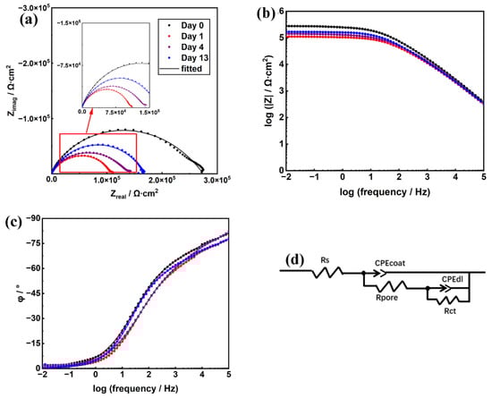
Figure 8.
EIS spectra (a–c) and EECs for the data fitting (d) of 2CB-67Zn on days 0, 1, 4 and 13.
Table 3.
Fitted CPEcoat, Rpore, CPEdl and Rct values of 2CB-67Zn.
For 2CB-67Zn, the Nyquist plot presented double capacitive resistance with a diffusion tail, and the Bode modulus plot also exhibited two time constants at each of the four immersion times (0 day, 1 day, 4 days and 13 days). One time constant corresponded to the coating capacitance (CPEcoat) and the micropore resistance inside the coating film (Rpore), and the other time constant referred to the double layer capacitance between the electrolyte solution and the steel substrate (CPEdl) and the charge transfer resistance (Rct) of the metal substrate. The low values of the mean square of the residual (χ2) demonstrated that the fitting results were accurate. Warburg diffusion was not observed at all four time points, indicating that the electrode process was still dominated by charge transfer after 13 days. Figure 8a indicates that the electrolyte contacted the metal substrate interface and corrosion began to occur at day 0 (20 min), while the cathodic protection provided by 2CB-67Zn according to the OCP analysis was not observed due to the limitation of the sensitivity of the instrument. Table 3 shows that the Rct and CPEdl values remained at 106 Ω cm2 and 10−8 Qdl/Ω−1∙cm−2∙sα, respectively, after 13 days, which were equal to those at the initial moment. The high Rct and low CPEdl values of the 2CB-67Zn coating suggested that the CB-modified coatings demonstrated good anti-corrosion properties.
3.4. Comparative Study of the Influence of Conductive Additives in Zinc-Rich Primers
Based on the salt spray and electrochemical testing results, we determined a possible corrosion-protection mechanism of the influence of conductive additives on zinc-rich primers. It is demonstrated, in this work, that conductive additives can act as a “bridge” to increase the electron transport path between the zinc particles inside the coatings (Figure 9), thus improving the galvanic protection behavior of the coatings and the steel substrate, which is consistent with the results of previously reported research [39,40]. Though the introduction of conductive powders increased the electrical percolation of the modified ZRP coatings in essence, the four conductive powders played different roles within the ZRP. Therefore, depending on the conductivities of powders, the salt spray test results, as well as the electrochemical results of the unmodified and modified coatings, a deeper mechanism related to the effects of the types and additive contents of the conducting powders on the anti-corrosion property was proposed.
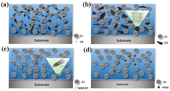
Figure 9.
Schematic representation of anti-corrosion mechanisms in conductive additive modified zinc-rich epoxy coatings: (a) XCB-YZn, (b) XCG-YZn series, (c) XMWCNT-YZn series and (d) XPANI-YZn series.
According to the salt-spray test results, the CB-modified ZRP coatings exhibited the best anti-corrosion performance, with the lowest conductivity of CB powders compared with those of the CG and MWCNT powders (Figure 9a). More electron flow paths are available to connect the zinc dust for the nanosized spherical CB, which was smaller than the lamellar CG sheets and MWCNT powders. Additionally, the arrangement of three incorporated contents (1 wt.%, 2 wt.% and 4 wt.%) of carbon black was reasonable, especially in the case of 2CB-67Zn, resulting in prominent salt spray resistance together with low OCP values.
The sheet-like structure of CG zigzagged the pathway of electron flow, preventing the diffusion of oxygen and electrolytes from the coating to the metal substrate [41] (Figure 9b). This is the reason for the salt spray resistance of 2CG-67Zn and 4CG-67Zn not being inferior to that of the control coating (Zn80). The CG-modified series was inferior to the CB-modified series due to the poor chemically bonded interface junction between the epoxy resin and the CG powders, based on previous investigations [42]. According to the review of Fitzer and Weiss [42,43], the chemical bonding reaction between the epoxy resin and carbonaceous powders tended to occur between the defective and incompletely bonded edge carbon atoms, rather than the completely bonded carbon atoms that were chemically inert. Since the value of ID/IG (ID/IG = 0.06) of the CG powders was significantly lower than that ((ID/IG = 1.36) of the CB powders, there were more chemically inert carbon atoms in CG that could not easily bond with the epoxy resin, thus causing the CG-modified coating defects and poor corrosion resistance. A small addition of less than 1 wt.% may be sufficient for CG-modified coatings, and it seems that, with the increase in CG addition, the large number of flakes were inclined to gather to agglomerate and further prevent their corrosion-protection performance from being displayed. The findings of the current study are consistent with those of Chunping Qi et al. [44], who found that only the coatings loaded with 5.0 and 2.5 wt.% stainless-steel flakes, rather than 10 wt.% stainless-steel flakes, exhibited enhanced anticorrosion performance based on the synergistic effects of barrier and cathodic protection.
With regard to MWCNT, it has been widely reported that MWCNT is a popular conductive additive for the reinforcement of the galvanic effect between the zinc particles and metal substrate, and, indeed, the MWCNT-modified coatings showed cathodic protection according to the electrochemical test. However, for the salt spray test results, the corrosion resistance of the MWCNT-modified ZRP coatings was the worst among the four modified series. This discrepancy can be ascribed to the following reasons: (1) The high oil absorptivity of MWNCT led to agglomerates of long tubes evolving, which could not be wetted and dispersed by the inadequate resin in contrast to the other conductive powders [6]. The local agglomerations of MWCNT significantly increased the galvanic effect and caused a large sacrifice of zinc particles. (2) The electrical percolation thresholds of ZRP coatings, i.e., the critical concentration at which the composite transformed from an insulator to a conductor [9], varied with the types of ZRP coatings. This suggests that the formula of the MWCNT-modified series used in this study seemed to far exceed the critical value, thus forming a conductive chain between the MWCNTs and zinc particles, instead of the zinc particles and metal substrate. (3) The introduction of pristine MWCNT powders (ID/IG = 1.19), which contained more chemically inert carbon atoms than CB powders (ID/IG = 1.36), caused more defects at the MWCNT/epoxy resin interfaces [42,45]. As a result, the MWCNT-modified coatings developed defects associated with large amounts of corrosion products due to the rapid consumption of zinc dust. This is because MWCNTs have a lower percolation threshold due to their larger specific surface area than that of other conductive fillers, such as carbon black, carbon fiber, or metal pigments [16]. The present findings are in agreement with Ewa Langer’s findings, which showed that, at a CNT concentration of 0.4 wt.% and a zinc dust content of 70 wt.%, the corrosion resistance of the coating was increased [46].
Compared with carbonaceous powders, the conducting polymer (PANI) showed more special functionalities together with conductivity. E. Akbarinezhad synthesized a conductive polyaniline–graphite nanocomposite by supercritical CO2 and found that the modified PANI provided cathodic protection for ZRPs [19]. Yanhua Lei et al. [38] reported that the improvement of the anticorrosion performance of the coating was attributed to the barrier properties of 1 wt.% polyaniline–graphite (PAniG) incorporated into the ZRP with 80 wt.% zinc dust. In our study, the PANI-modified ZRPs provided good shielding protection during the early stage and additional cathodic protection during the later stage. According to the low conductivity value at 2 MPa measured by a four-probe conductivity meter and the material information provided by the supplier, the PANI applied in this study was originally in a neutral intrinsic state, i.e., PANI emeraldine base (PANI-EB), which is considered effective in barriers and corrosion inhibition [47,48]. Then, the PANI-EB was inclined to accept protons generated at the metal substrate’s surface by electrolyte percolation and, in the case of chloride anion induction, the conversion of PANI-EB to a doped state, i.e., PANI-ES, was completed [49]. PANI-ES is helpful for reducing the zinc content by increasing the electron transport pathways [50] and can generate an electric field to restrict the flow of electrons from the substrate to the external oxygen, thus preventing corrosion [8]. A dense oxide film that is capable of blocking electrolyte and oxygen penetration will be formed on the metal surface owing to the initiation of PANI-ES for metal passivation. The corrosion mechanism of the PANI-modified series was supported by and well in agreement with the electrochemical testing results.
4. Conclusions
In this work, four commonly used conductive powders, i.e., carbon black (CB), conductive graphite (CG), multiwalled carbon nanotubes (MWCNTs) and polyaniline (PANI), which can be divided into conducting carbonaceous powders and polymers, were incorporated into ZRP formulations to partially replace the zinc dust. The coatings of the CB-modified series showed better salt spray corrosion resistance than the original powder, even in the case of 67 wt.% Zn, over 500 h. The conductive effect of the nanosized carbon black clusters was further demonstrated by the open circuit potentials, which were stable below −0.80 V. The 67 wt.% zinc dust with 2 wt.% CB was confirmed to be one of the most favorable arrangements due to the excellent coating anti-corrosion characteristics and the observed high Rct value (106 Ω cm2) and low CPEdl value (10−8 Ω−1 cm−2∙sα).
Compared with CB, CG, with the highest electrical conductivity, could not be uniformly dispersed in the coatings due to its lamellar structure, thus limiting the construction of the electron transport path between the separated zinc particles. Nevertheless, it seems that the lamellar graphite could provide a good shielding effect when its addition was no more than 1 wt.%. The MWCNT-modified coatings showed extremely low OCP potential, but quite poor resistance against salt spray. Considering the high electrical conductivity of MWCNT, tailoring the MWCNT content incorporated in the coating was of great concern to increase the electron pathways without causing severe local galvanic effects. PANI can be regarded as a conducting polymer and a blocking agent against corrosion, depending on the mixed corrosion resistance mechanism.
The comparative results provide valuable information on the utilization of conductive additives to partially substitute zinc dust in zinc-rich primers and are valuable for further basic research and commercial applications. This study suggests that there are four different types of conductive additives available; carbon black is an especially good alternative for the improvement of corrosion resistance.
Author Contributions
Conceptualization, H.Z. (Haiping Zhang), H.Z. (Hui Zhang), Y.S., J.Z. and X.L.; methodology, H.Z. (Haiping Zhang) and X.L.; validation, H.Z. (Haiping Zhang) and X.J.; formal analysis, X.L. and L.Z.; investigation, X.L., X.J. and Z.Z.; resources, X.J., L.Z., Y.S. and J.Z.; data curation, H.Z. (Haiping Zhang), X.L. and Y.B.; writing—original draft preparation, X.L.; writing—review and editing, X.L., Z.Z., H.Z. (Haiping Zhang), T.G., L.Z., B.Y., A.Y., J.N., F.C. and Z.X.; supervision, H.Z. (Haiping Zhang), H.Z. (Hui Zhang), Y.S., J.Z. and T.G.; project administration, Y.S., H.Z. (Hui Zhang), X.J., T.G., L.Z., B.Y., A.Y., J.N., F.C. and Z.X.; funding acquisition, X.J., T.G., L.Z., B.Y., A.Y., J.N., F.C. and Z.X. All authors have read and agreed to the published version of the manuscript.
Funding
Datang North China Electric Power Test and Research Institute.
Institutional Review Board Statement
Not applicable.
Informed Consent Statement
Not applicable.
Data Availability Statement
Not applicable.
Conflicts of Interest
The authors declare no conflict of interest.
References
- Hare, C.H. Zinc-rich primers I: Design principles. J. Prot. Coat. Linings 1998, 15, 13. [Google Scholar]
- Hussain, A.K.; Seetharamaiah, N.; Pichumani, M.; Chakra, C.S. Research progress in organic zinc rich primer coatings for cathodic protection of metals—A comprehensive review. Prog. Org. Coat. 2021, 153, 106040. [Google Scholar] [CrossRef]
- Marchebois, H.; Touzain, S.; Joiret, S.; Bernard, J.; Savall, C. Zinc-rich powder coatings corrosion in sea water: Influence of conductive pigments. Prog. Org. Coat. 2002, 45, 415–421. [Google Scholar] [CrossRef]
- Park, S.; Shon, M. Effects of multi-walled carbon nano tubes on corrosion protection of zinc rich epoxy resin coating. J. Ind. Eng. Chem. 2015, 21, 1258–1264. [Google Scholar] [CrossRef]
- Zhang, W.-G.; Li, L.; Yao, S.-W.; Zheng, G.-Q. Corrosion protection properties of lacquer coatings on steel modified by carbon black nanoparticles in NaCl solution. Corros. Sci. 2007, 49, 654–661. [Google Scholar] [CrossRef]
- Kalendová, A.; Veselý, D.; Kohl, M.; Stejskal, J. Anticorrosion efficiency of zinc-filled epoxy coatings containing conducting polymers and pigments. Prog. Org. Coat. 2015, 78, 1–20. [Google Scholar] [CrossRef]
- Liu, J.; Wang, F.; Park, K. Study on corrosive electrochemical behaviors of zinc-rich and graphite-filled epoxy coatings in 3.5 wt% NaCl solution. Mater. Corros. 2011, 62, 1008–1014. [Google Scholar] [CrossRef]
- Meroufel, A.; Deslouis, C.; Touzain, S. Electrochemical and anticorrosion performances of zinc-rich and polyaniline powder coatings. Electrochim. Acta 2008, 53, 2331–2338. [Google Scholar] [CrossRef]
- Cubides, Y.; Castaneda, H. Corrosion protection mechanisms of carbon nanotube and zinc-rich epoxy primers on carbon steel in simulated concrete pore solutions in the presence of chloride ions. Corros. Sci. 2016, 109, 145–161. [Google Scholar] [CrossRef]
- Gergely, A.; Pászti, Z.; Mihály, J.; Drotár, E.; Török, T. Galvanic function of zinc-rich coatings facilitated by percolating structure of the carbon nanotubes. Part II: Protection properties and mechanism of the hybrid coatings. Prog. Org. Coat. 2014, 77, 412–424. [Google Scholar] [CrossRef]
- Popkirov, G.S.; Schindler, R.N. Validation of experimental data in electrochemical impedance spectroscopy. Electrochim. Acta 1993, 38, 861–867. [Google Scholar] [CrossRef]
- Armelin, E.; Alemán, C.; Iribarren, J.I. Anticorrosion performances of epoxy coatings modified with polyaniline: A comparison between the emeraldine base and salt forms. Prog. Org. Coat. 2009, 65, 88–93. [Google Scholar] [CrossRef]
- Ramezanzadeh, B.; Moghadam, M.M.; Shohani, N.; Mahdavian, M. Effects of highly crystalline and conductive polyaniline/graphene oxide composites on the corrosion protection performance of a zinc-rich epoxy coating. Chem. Eng. J. 2017, 320, 363–375. [Google Scholar] [CrossRef]
- DeBerry, D.W. Modification of the electrochemical and corrosion behavior of stainless steels with an electroactive coating. J. Electrochem. Soc. 1985, 132, 1022. [Google Scholar] [CrossRef]
- Kalendová, A.; Veselý, D.; Stejskal, J. Organic coatings containing polyaniline and inorganic pigments as corrosion inhibitors. Prog. Org. Coat. 2008, 62, 105–116. [Google Scholar] [CrossRef]
- Li, G.; Feng, L.; Tong, P.; Zhai, Z. The properties of MWCNT/polyurethane conductive composite coating prepared by electrostatic spraying. Prog. Org. Coat. 2016, 90, 284–290. [Google Scholar] [CrossRef]
- Liu, K.; Qian, M.; Fan, L.; Zhang, S.; Zeng, Y.; Huang, F. Dehalogenation on the surface of nano-templates: A rational route to tailor halogenated polymer-derived soft carbon. Carbon 2020, 159, 221–228. [Google Scholar] [CrossRef]
- Fu, R.; Ji, J.; Yun, L.; Jiang, Y.; Zhang, J.; Zhou, X.; Liu, Z. Graphene wrapped silicon suboxides anodes with suppressed Li-uptake behavior enabled superior cycling stability. Energy Storage Mater. 2021, 35, 317–326. [Google Scholar] [CrossRef]
- Akbarinezhad, E. Synthesis of conductive polyaniline–graphite nanocomposite in supercritical CO2 and its application in zinc-rich epoxy primer. J. Supercrit. Fluids 2014, 94, 8–16. [Google Scholar] [CrossRef]
- Marinho, B.; Ghislandi, M.; Tkalya, E.; Koning, C.E.; de With, G. Electrical conductivity of compacts of graphene, multi-wall carbon nanotubes, carbon black, and graphite powder. Powder Technol. 2012, 221, 351–358. [Google Scholar] [CrossRef]
- Kendall, K. Solid surface energy measured electrically. J. Phys. D Appl. Phys. 1990, 23, 1329. [Google Scholar] [CrossRef]
- Kirby, R.K.; Hahn, T.A.; Rothrock, B.D. American Institute of Physics Handbook; Gray, D.E., Ed.; McGraw-Hill Publ. Co.: New York, NY, USA, 1972; Volume 4. [Google Scholar]
- Wu, C.Y.; Benatar, A. Microwave welding of high density polyethylene using intrinsically conductive polyaniline. Polym. Eng. Sci. 1997, 37, 738–743. [Google Scholar] [CrossRef]
- Cancado, L.G.; Jorio, A.; Ferreira, E.; Stavale, F.; Ferrari, A.C. Quantifying Defects in Graphene via Raman Spectroscopy at Different Excitation Energies. Nano Lett. 2012, 11, 3190–3196. [Google Scholar] [CrossRef] [PubMed]
- Quan, Y.; Liu, Q.; Li, K.; Zhang, H.; Yuan, L. Highly efficient purification of natural coaly graphite via an electrochemical method. Sep. Purif. Technol. 2022, 281, 119931. [Google Scholar] [CrossRef]
- Wall, M. The Raman spectroscopy of graphene and the determination of layer thickness. Thermo Sci. 2011, 5, 1–5. [Google Scholar]
- Pantea, D.; Darmstadt, H.; Kaliaguine, S.; Sümmchen, L.; Roy, C. Electrical conductivity of thermal carbon blacks: Influence of surface chemistry. Carbon 2001, 39, 1147–1158. [Google Scholar] [CrossRef]
- Lu, Y.; Wang, Y.; Zhang, L.; Wang, W. Preparation and characterization of dopamine-decorated hydrophilic carbon black. Appl. Surf. Sci. 2012, 281, 119931. [Google Scholar]
- Song, P.; Wan, C.; Xie, Y.; Zhang, Z.; Wang, S. Stepwise exfoliation of bound rubber from carbon black nanoparticles and the structure characterization. Polym. Test. 2018, 71, 115–124. [Google Scholar] [CrossRef]
- Chen, X.; Wang, X.; Fang, D. A review on C1s XPS-spectra for some kinds of carbon materials. Fuller. Nanotub. Carbon Nanostructures 2020, 28, 1048–1058. [Google Scholar] [CrossRef]
- Pantea, D.; Darmstadt, H.; Kaliaguine, S.; Blacher, S.; Roy, C. Surface morphology of thermal, furnace and pyrolytic carbon blacks by nitrogen adsorption-relation to the electrical conductivity. Rubber Chem. Technol. 2002, 75, 691–700. [Google Scholar] [CrossRef]
- Jara, A.D.; Betemariam, A.; Woldetinsae, G.; Kim, J.Y. Purification, application and current market trend of natural graphite: A review. Int. J. Min. Sci. Technol. 2019, 29, 671–689. [Google Scholar] [CrossRef]
- Pitchan, M.K.; Bhowmik, S.; Balachandran, M.; Abraham, M. Process optimization of functionalized MWCNT/polyetherimide nanocomposites for aerospace application. Mater. Des. 2017, 127, 193–203. [Google Scholar] [CrossRef]
- Rui, M.; Jiang, Y.; Zhu, A. Sub-micron calcium carbonate as a template for the preparation of dendrite-like PANI/CNT nanocomposites and its corrosion protection properties. Chem. Eng. J. 2020, 385, 123396. [Google Scholar] [CrossRef]
- Bernard, M.; Hugot-Le Goff, A.; Massinon, D.; Phillips, N. Underpaint corrosion of zinc-coated steel sheet studied by in situ Raman spectroscopy. Corros. Sci. 1993, 35, 1339–1349. [Google Scholar] [CrossRef]
- Bernard, M.; Hugot-Le Goff, A.; Phillips, N. In Situ Raman Study of the Corrosion of Zinc-Coated Steel in the Presence of Chloride: I. Characterization and Stability of Zinc Corrosion Products. J. Electrochem. Soc. 1995, 142, 2162. [Google Scholar] [CrossRef]
- Langer, E.; Zubielewicz, M.; Kuczyńska, H.; Królikowska, A.; Komorowski, L. Anticorrosive effectiveness of coatings with reduced content of Zn pigments in comparison with zinc-rich primers. Corros. Eng. Sci. Technol. 2019, 54, 627–635. [Google Scholar] [CrossRef]
- Lei, Y.; Qiu, Z.; Liu, J.; Li, D.; Tan, N.; Liu, T.; Zhang, Y.; Chang, X.; Gu, Y.; Yin, Y. Effect of conducting polyaniline/graphene nanosheet content on the corrosion behavior of zinc-rich epoxy primers in 3.5% NaCl solution. Polymers 2019, 11, 850. [Google Scholar] [CrossRef]
- Xie, D.-M.; Huang, K.; Feng, X.; Wang, Y.-G. Improving the performance of zinc-rich coatings using conductive pigments and silane. Corros. Eng. Sci. Technol. 2020, 55, 539–549. [Google Scholar] [CrossRef]
- Gergely, A.; Pászti, Z.; Mihály, J.; Drotár, E.; Török, T. Galvanic function of zinc-rich coatings facilitated by percolating structure of the carbon nanotubes. Part I: Characterization of the nano-size particles. Prog. Org. Coat. 2015, 78, 437–445. [Google Scholar] [CrossRef]
- Pourhashem, S.; Vaezi, M.R.; Rashidi, A.; Bagherzadeh, M.R. Exploring corrosion protection properties of solvent based epoxy-graphene oxide nanocomposite coatings on mild steel. Corros. Sci. 2017, 115, 78–92. [Google Scholar] [CrossRef]
- Hughes, J. The carbon fibre/epoxy interface—A review. Compos. Sci. Technol. 1991, 41, 13–45. [Google Scholar] [CrossRef]
- Fitzer, E.; Weiss, R. 223. Adhesion problems between carbon fibres and polymers in CFRP. Carbon 1982, 20, 149. [Google Scholar] [CrossRef]
- Qi, C.; Dam-Johansen, K.; Weinell, C.E.; Bi, H.; Wu, H. Enhanced anticorrosion performance of zinc rich epoxy coatings modified with stainless steel flakes. Prog. Org. Coat. 2022, 163, 106616. [Google Scholar] [CrossRef]
- Li, Y.; Li, R.; Fu, X.; Wang, Y.; Zhong, W.-H. A bio-surfactant for defect control: Multifunctional gelatin coated MWCNTs for conductive epoxy nanocomposites. Compos. Sci. Technol. 2018, 159, 216–224. [Google Scholar] [CrossRef]
- Gergely, A.; Török, T.; Pászti, Z.; Bertóti, I.; Mihály, J.; Kálmán, E. Zinc-rich paint coatings containing either ionic surfactant-modified or functionalized multi-walled carbon nanotube-supported polypyrrole utilized to protect cold-rolled steel against corrosion. In Application of Carbon Nanotubes; Nova Science Publishers: New York, NY, USA, 2013. [Google Scholar]
- Ansari, R.; Alikhani, A.H. Application of polyaniline/nylon composites coating for corrosion protection of steel. J. Coat. Technol. Res. 2009, 6, 221–227. [Google Scholar] [CrossRef]
- Armelin, E.; Ocampo, C.; Liesa, F.; Iribarren, J.I.; Ramis, X.; Alemán, C. Study of epoxy and alkyd coatings modified with emeraldine base form of polyaniline. Prog. Org. Coat. 2007, 58, 316–322. [Google Scholar] [CrossRef]
- Armelin, E.; Martí, M.; Liesa, F.; Iribarren, J.I.; Alemán, C. Partial replacement of metallic zinc dust in heavy duty protective coatings by conducting polymer. Prog. Org. Coat. 2010, 69, 26–30. [Google Scholar] [CrossRef]
- Wessling, B. Corrosion prevention with an organic metal (polyaniline): Surface ennobling, passivation. Mater. Corros. 1996, 47, 439–445. [Google Scholar] [CrossRef]
Publisher’s Note: MDPI stays neutral with regard to jurisdictional claims in published maps and institutional affiliations. |
© 2022 by the authors. Licensee MDPI, Basel, Switzerland. This article is an open access article distributed under the terms and conditions of the Creative Commons Attribution (CC BY) license (https://creativecommons.org/licenses/by/4.0/).