Article

Experimental Research on Dynamic Response of Layered Medium under Impact Load

1
College of Architecture and Energy Engineering, Wenzhou University of Technology, Wenzhou 325035, China
2
Wenzhou Key Laboratory of Intelligent Lifeline Protection and Emergency Technology for Resilient City, Wenzhou University of Technology, Wenzhou 325035, China
3
College of Design and Art, Wenzhou University of Technology, Wenzhou 325035, China
*
Author to whom correspondence should be addressed.
Coatings 2022, 12(10), 1474; https://doi.org/10.3390/coatings12101474
Submission received: 7 September 2022 / Revised: 25 September 2022 / Accepted: 27 September 2022 / Published: 5 October 2022
(This article belongs to the Special Issue Current Research in Cement and Building Materials)

Abstract

:
Stress waves propagating through multiple parallel fractures are attenuated due to the multiple wave reflections and transmissions at the fractures. The dynamic response of a layered medium under an impact load is systematically studied by a model test in this paper. The effects of the impact energy, number of joints, thickness of the medium and joint layer, material properties of the cementation layer, and other factors of the dynamic stress propagation and attenuation of layered media are analyzed. Studies have shown that Sadovsky’s empirical formula fits the attenuation law of vertical peak velocity well, and the obtained attenuation coefficient k and index b can be used for reflecting the dynamic response characteristics of layered media. The attenuation coefficient k is positively correlated with the impact height and negatively correlated with the plate thickness in a single-layer plate impact test. The thickness of the medium layer is the main factor affecting the vibration response of the layered medium in the impact test of the multi-layer slab. The medium thickness, the number of medium layers, and the number of joints have little influence. The different cementation materials and the change of cementation thickness will have a great influence on the dynamic response of layered media, when the cementation layer is filled with joint surfaces for the impact test of multi-layer plates.

1. Introduction

The research on the dynamic properties of a layered medium has always been an important topic in geotechnical engineering, such as for the safety protection of a military underground structure, mine blasting or excavation blasting, the excavation of a metro tunnel or an underground pipe rack, the design of a roadbed or a pavement structure, or the vibration prediction of the blasting demolition of a structure. The propagation characteristics of stress waves in layered media need to be deeply studied and understood in these fields.
Generally, three methods are available for studies on wave propagation of a layered medium. One is the theoretical study from which the mechanism and the process of wave propagation can be revealed for some special geological cases. The experimental study is the second method, which is sometimes limited by the existing test techniques. The third is numerical modeling, which provides a convenient and economical approach, especially for complicated geological cases.
The most classical theoretical model is the displacement discontinuity model [1,2], which assumes that when waves propagate across a fracture, the stress field is continuous, but the displacement field is discontinuous due to the fracture deformation. On the basis of the displacement discontinuity model and Snell’s law, propagation of wave incidence across a planar linear slip interface was investigated by Schoenberg [3,4]. Many scholars have further extended the displacement discontinuous model. The effects of different joint quantities, joint geometric characteristics, stress wave incident conditions, and rock mass and joint media material deformation characteristics on the propagation characteristics of the stress wave in jointed media were considered. The wave propagation across parallel fractures and the permeation and reflection characteristics of joint surfaces were studied by Pyrak-Nolte [5,6] and Cook [7,8]. Chai S.B. [9] and Zhu [10] studied the wave transmission across jointed rock masses, where multiple intersecting joint sets exist. Goodman R.E. [11], Lu [12], Li [13], and Ju [14] considered the influence of the characteristics of the joint layer, such as joint stiffness, physical and mechanical properties of joint-filled media, joint surface boundary condition, and transfer condition. Pyrak-Nolte [5] and Gu [15,16] discussed the relationship between the transmittance and the reflection coefficient, the waveform conversion phenomenon, and the incident angle and derived the transfer equation of the incident angle. Cai [17] and Zhao [18,19,20] analyzed the effects of the linear and nonlinear deformation characteristics of the joint layer.
Although the wave propagation across different topography joints, such as single or groups of parallel joints and simple intersecting joints, have been considered in the existing theoretical research. However, it is difficult to accurately analyze and evaluate by theoretical methods in actual engineering, due to the complexity of joint distribution and the inaccuracy of the mechanics and boundary conditions. Therefore, many researchers have done a lot of work through the more intuitive research method of experiment. Generally, the Split Hopkinson Pressure Bar (SHPB) apparatus was adopted to investigate the wave propagation of a layered medium. Ju [14], Wang [21], Lu [22], and Li [23] studied the propagation characteristics of one-dimensional stress waves in layered media through the fractal theory and analyzed the transmittance and reflection properties at the joints and the effects of the fractal dimension and roughness of the joints. Similarly, based on SHPB test equipment, the influence of impact rate, strain rate, joint angle, joint thickness, and other parameters was studied by Li [23], Yang [24], Wei [25], and Challita G. [26]. In addition to the SHPB test system, Tian [27] and Sun [28] carried out some research with independently developed impact test equipment. Based on actual blasting engineering, Peng [29] and Wang [30] analyzed the wave attenuation of a natural layered foundation and improved the empirical formula of stress wave propagation.
For the numerical modeling, the same problem was studied with the many available tools, such as the finite element method (FEM), boundary element method (BEM), finite difference method (FDM), and discrete element method (DEM). In FEM and BEM, joints are modeled using “joint elements”, which simulate the interface discontinuity [31,32]. In FDM, joints are simulated using slide-lines [33]. Compared with the other methods, DEM has been recognized as a better alternative. The layered medium is treated as an assemblage of discrete blocks by fictitious or real joints, of which some are the contact interfaces between the distinct bodies [34]. In recent years, the universal distinct element code (UDEC), which is a 2D DEM-based numerical program, has been widely adopted to study wave propagation across the joints of layered media [35]. Brady [36] performed UDEC modeling on the wave attenuation across a single joint. Zhao et al. [37,38] carried out numerical studies on wave propagation across multiple non-linearly deformable joints with UDEC. Deng [39] performed a study aimed to verify the capability of 3DEC to model wave propagation across joints in 3D space. Zhu [40] developed a newly numerical code, the distinct lattice spring model (DLSM), to study normally incident wave propagation across a joint set.
However, no experimental work has been conducted to systemically study the dynamic stress propagation and attenuation of a layered medium with parallel joints. In this paper, a self-developed concrete-slab-impact testing system is used to study the dynamic properties of the layered medium through the impact test of single-layer slab, multi-layer slab with parallel joints, and multi-layer slab with cementation. Firstly, the attenuation parameters are obtained by fitting the peak particle velocity with the empirical formula. Subsequently, parametric studies on impact energy, the number of joints, the thickness of the medium and joint layer, and the properties of the cementation layer are conducted. The dependence of wave propagation and attenuation on these parameters are discussed in detail.

2. Model Test Design

2.1. Specimen Dimension Determination

In order to eliminate the influence of the boundary effect, the numerical software LS-DYNA (960, 2001, ANSYS, Pittsburgh, PA, USA) was used to simulate the attenuation of peak particle velocity by modeling the hammer drop test on a three-layer concrete slab.

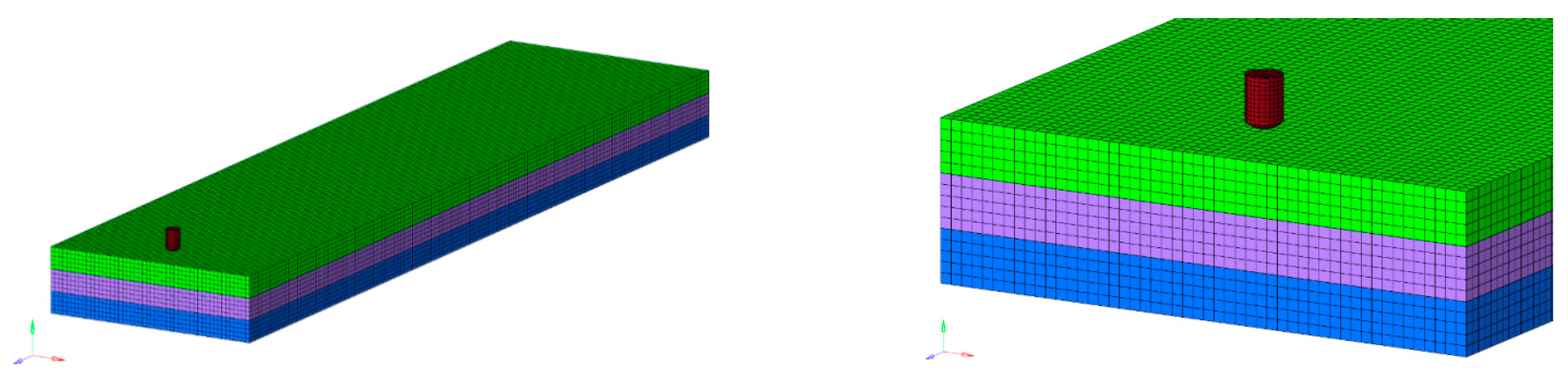
2.1.1. Calculation Model Establishment

The stress cloud diagram of the concrete slab was recorded to analyze the influence of boundary effect by applying the impact load of a 2.5 kg drop hammer on the surface, as shown in Figure 1. The SOLID164 element was used to build the concrete slab model, and the length of each slab is 4 m, the width is 1 m, and the thickness is 10 cm. The simulation in this paper adopts the projection boundary condition, which can simulate the effect of the wireless range in the finite range model. By applying artificial dampers to the boundary, the wave will be projected when it propagates to the boundary and then spreads to the infinite distance, as if it propagates in the infinite medium. The bottom concrete slab is fixed and restrained at the bottom. Surface-to-surface contact is set between each layer of the slab, and point-to-surface contact is set between the drop hammer and the upper layer of the slab.
Surface-to-surface contact is adopted for the contact type between each layer of slabs, and this kind of contact is one of the most commonly used contact types. It is commonly used for contact problems between objects with an arbitrary shape and a large contact area, such as block sliding, cylinder sliding, etc. Point-to-surface contact is adopted for the contact type between the drop hammer and the uppermost concrete slab. A continuous cap model MAT_159 (MAT_CSCM_CONCRETE) was used for the concrete, and a follow-up hardening model MAT_003 (MAT_PLASTIC_KINEMATIC) was used for the drop hammer.
In the impact model of LS-DYNA, the material constitutive model of concrete is usually the continuous cap model MAT_159 (MAT_CSCM_CONCRETE). The model requires fewer parameters and can take into account the strain-rate effect, which is very suitable for media that are sensitive to compressibility. The main parameters required are a density of 2.35 × 10⁻⁹ t/mm3, a compressive strength of 23.5 MPa, and an aggregate size of 10 mm. The material constitutive model of the drop hammer adopts the commonly used nonlinear plastic dynamic hardening model MAT_003 (MAT_PLASTIC_KINEMATIC). This model takes into account the strain-rate effect of the material, and the isotropy and dynamic hardening can be selected by adjusting the hardening parameters between 0–1. The strain rate is considered by the Cowper–Symonds model, and the factors related to the strain rate are used to express the yield stress, which is very suitable for metal materials under an explosive impact load.
The parameters of the concrete and drop hammer materials are shown in Table 1. The transmission boundary is adopted for the boundary condition, and the initial impact velocity of the drop hammer is defined as 4.849 m/s.

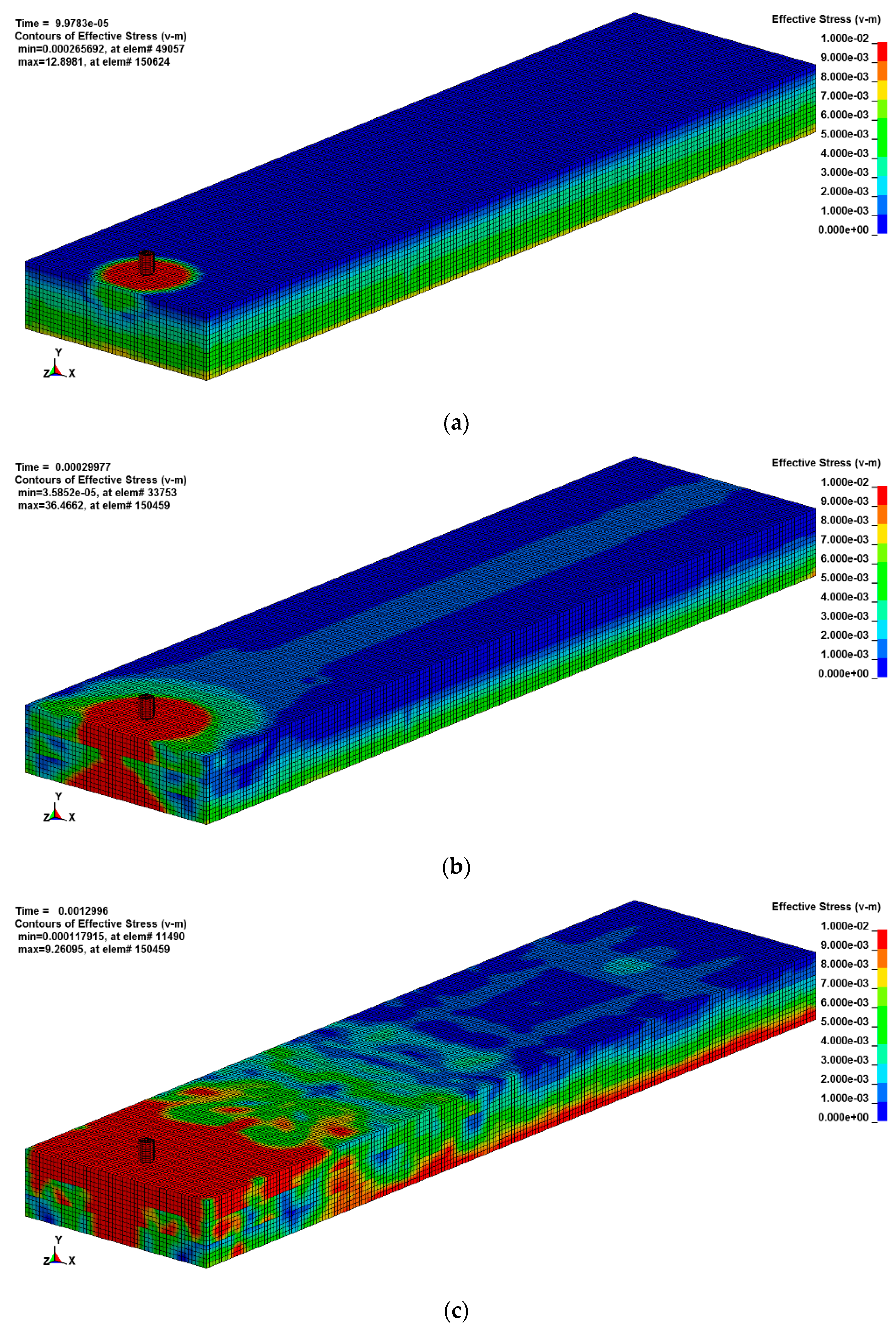
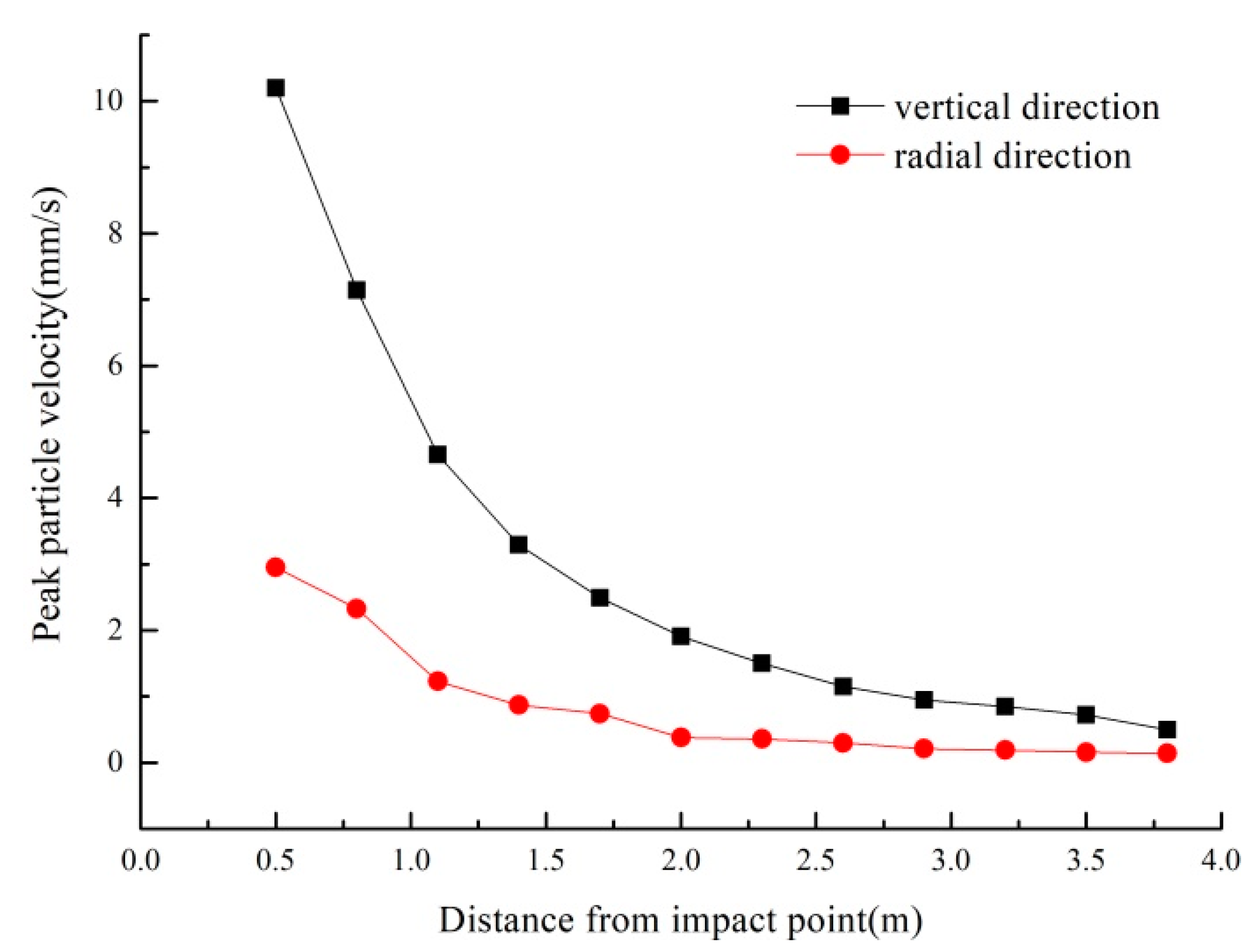
2.1.2. Numerical Results Analysis
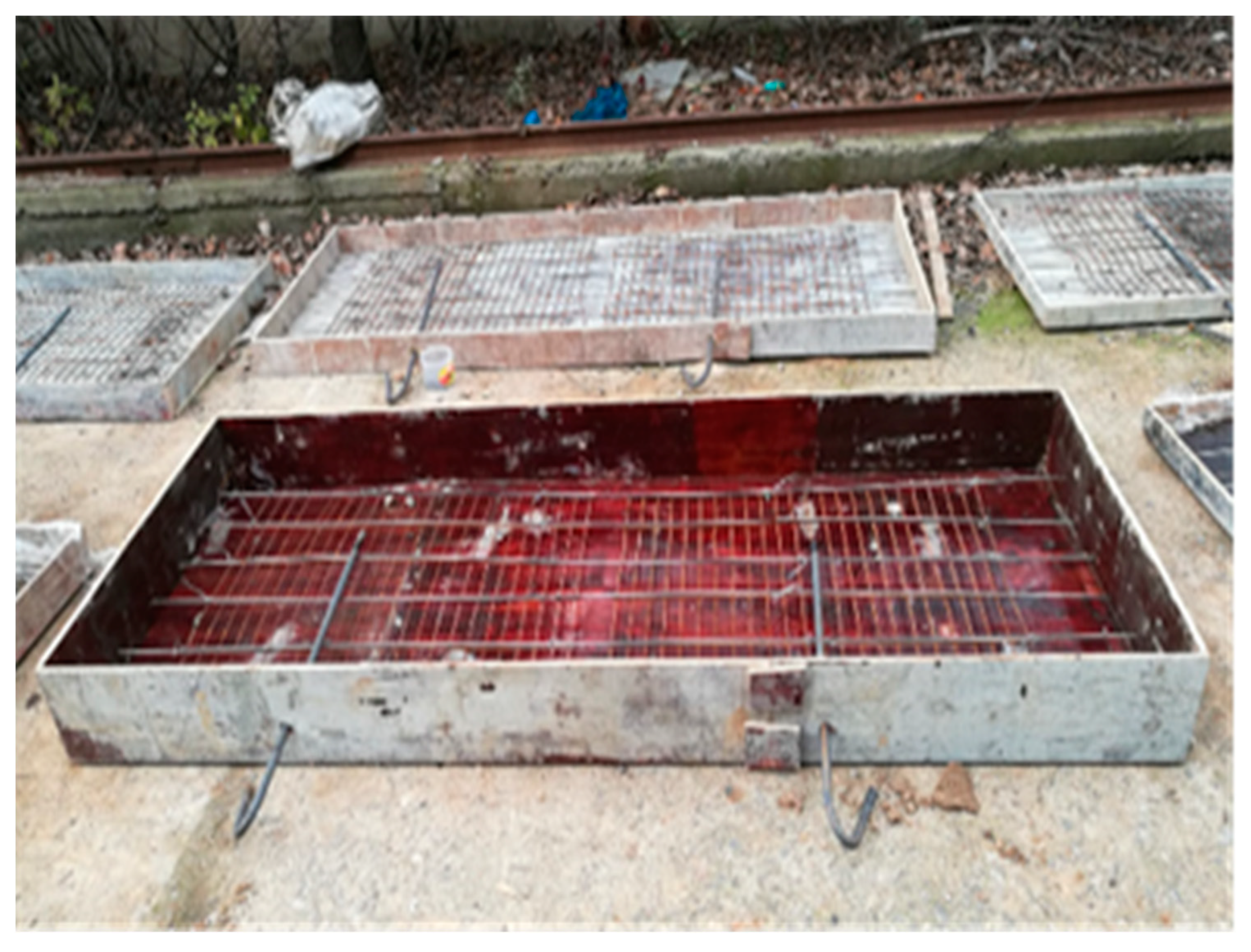
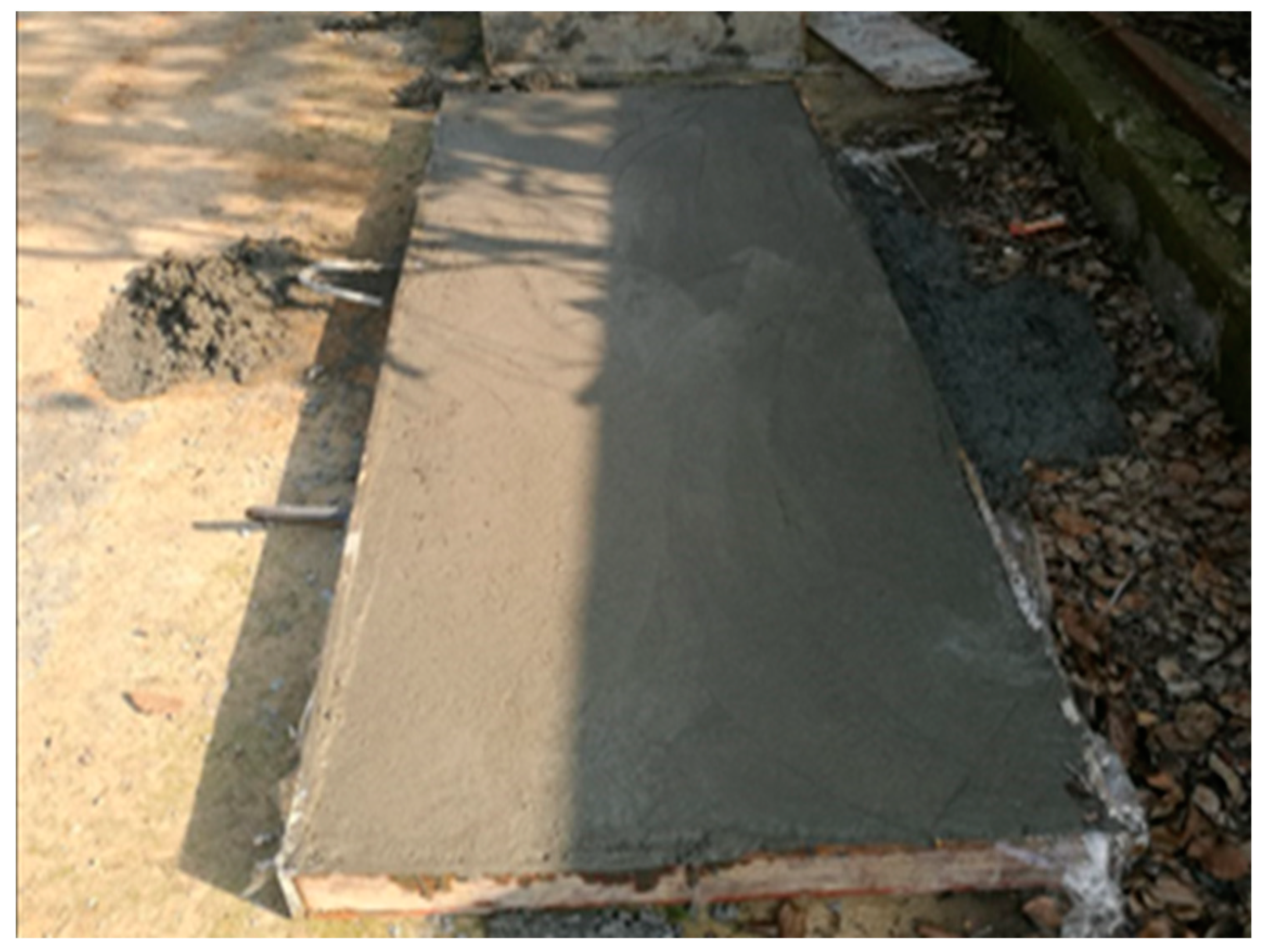
The direction stress cloud diagram of the concrete slab at different moments in the impact process is shown in Figure 2. The dynamic stress of the concrete slab shows gradual attenuation with the increase in impact distance. The horizontal influence range of the impact load is 2.5 m, and the stress response is very small, outside the range of 2.5 m. In the vertical direction, the dynamic stress shows an obvious jump attenuation across the joints, and a certain stress concentration appears at the interface between the layers. It can be seen that the joints have a significant effect on the dynamic propagation characteristics of the concrete slabs.
Figure 3 shows the vertical and radial peak particle velocity (PPV) values of each measurement point of the concrete surface in the horizontal direction. It can be seen that the attenuation of the vertical PPV is obviously greater than that of the radial PPV. The peak particle velocity tends to be stable when the measure point distance is greater than 2.5 m. Therefore, the final length of the concrete slab is determined to be 2.5 m.

2.2. Model Making

C30 fine aggregate concrete is selected as the concrete for model pouring, and the concrete ratio is water:cement:sand:gravel = 0.38:1:1.11:2.72, with 42.5 ordinary Portland cement used as the cement. Due to the small size of the model structure, melon seed chips are used as the stones, and the particle size is less than 20 mm.
Three kinds of cementitious materials with different elastic moduli are selected in this test, which are 1 cm EPE pearl cotton, 1 cm XPS extruded board, and 1 cm sand, respectively. The XPS extruded board and EPE pearl cotton are cut and pasted according to the width of the concrete slab and fixed on the concrete slab with adhesive tape to form a multi-layer slab.
Figure 4 and Figure 5 show the process of concrete-slab-mold making, steel binding, and specimen casting. Firstly, the model boxes were made according to the size of the specimen, as shown in Table 2. Then, the release agent was painted on the inner wall of the model boxes, and the steel was tied. The concrete was poured into the model in batches and vibrated fully with a vibrator. Meanwhile, the standard cube concrete test blocks were made and cured under the same condition during the casting processing of the specimens. The average uniaxial compressive strength of the five groups of specimens at 28 days was 23.64 MPa.

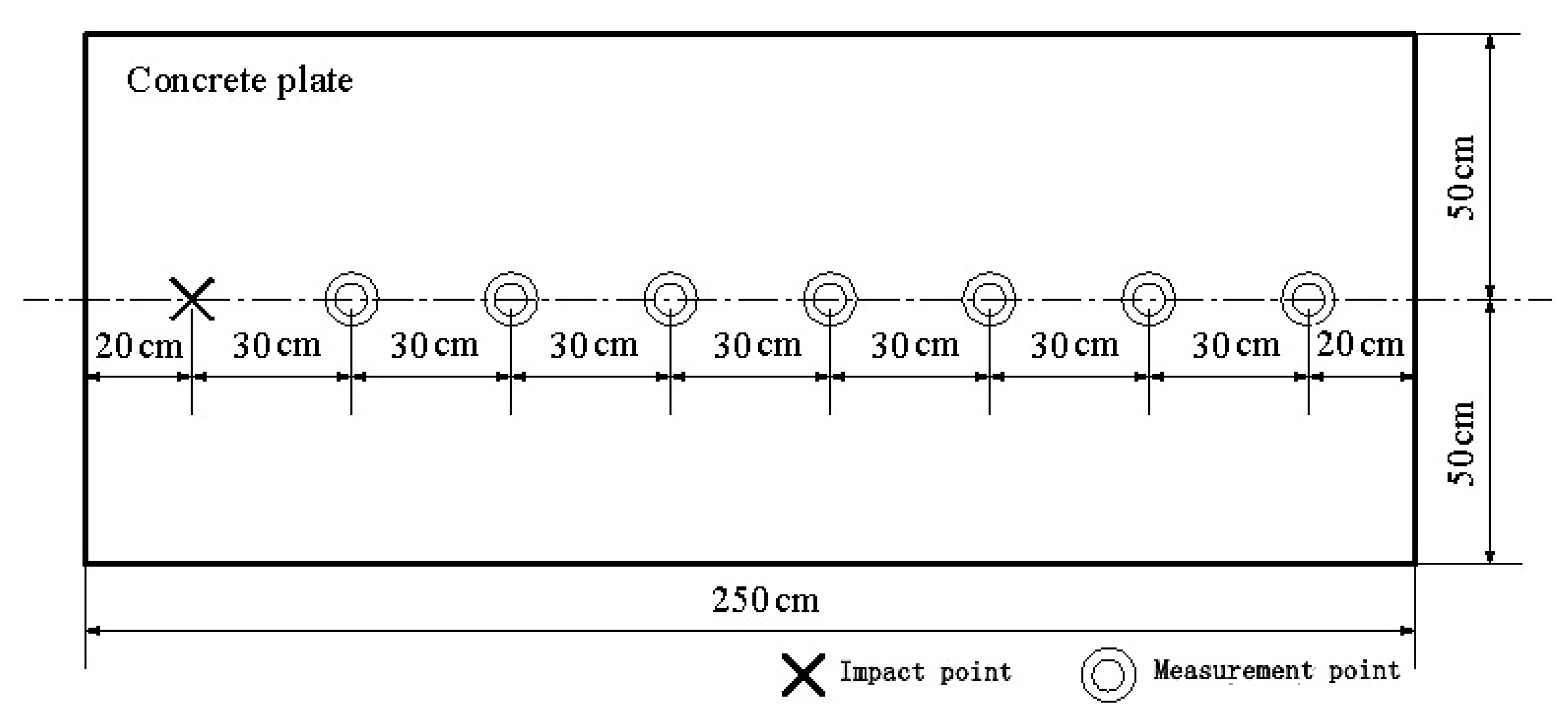
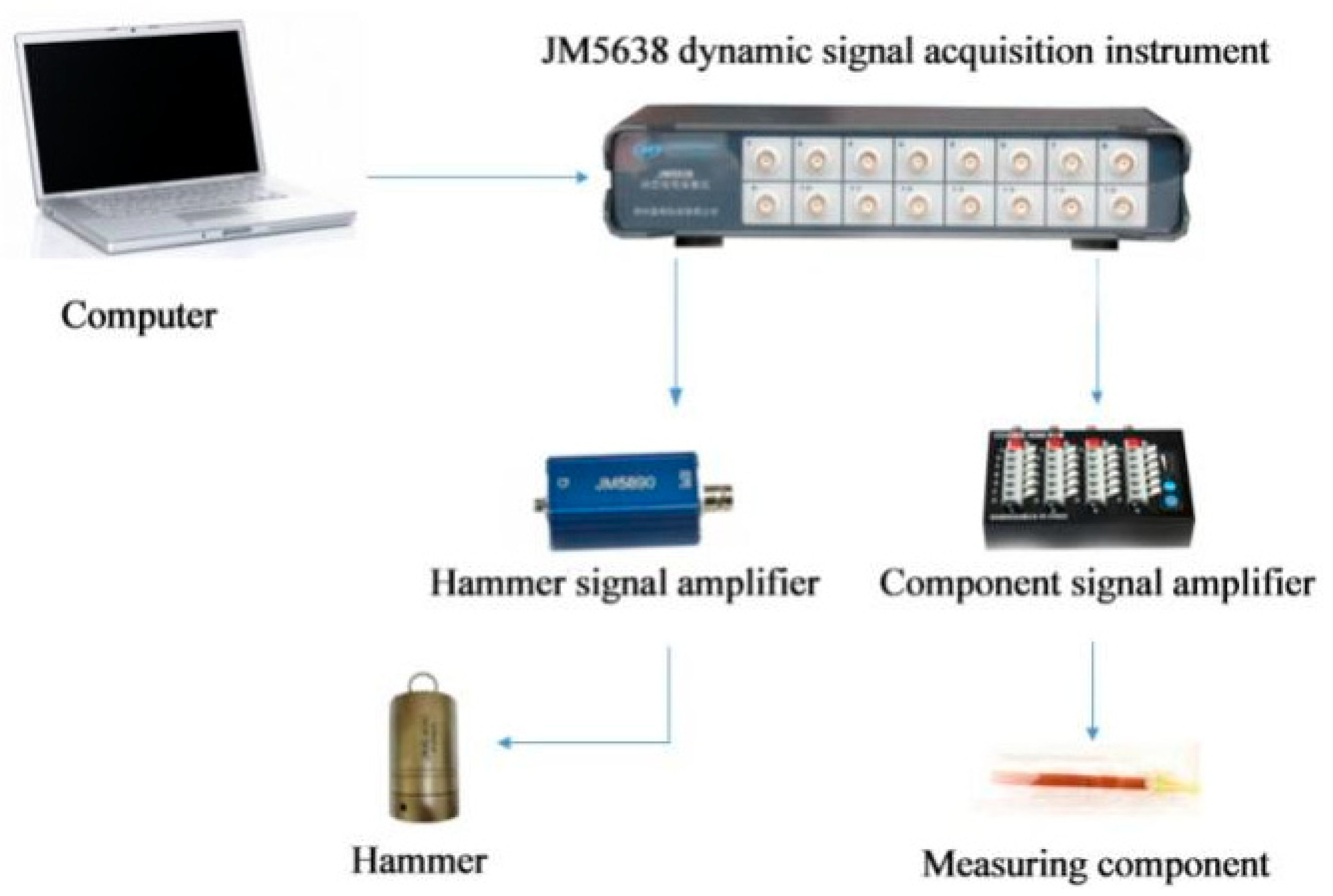
2.3. Testing Process

This paper uses Canada’s Minimate Pro4 vibration and overpressure monitor, which can be used to monitor the vibration velocity. The vibration sensors of the Minimate Pro4 vibration are arranged along the center line of the concrete surface, and the ranging is 0.3 m, 0.6 m, 0.9 m, 1.2 m, 1.5 m, 1.8 m, and 2.1 m, respectively, as shown in Figure 6. The concrete slab is placed on the ground freely without fixed constraint. In addition, the experimental acceleration of the fixed point was monitored. The 2.5 kg drop hammer was raised to the heights of 0.2 m, 0.4 m, 0.6 m, 0.8 m, 1.0 m, and 1.2 m, so that it can fall freely and impact the concrete slab. The JM5938 dynamic signal test and analysis system was used for signal acquisition, and its connection diagram is shown in Figure 7. Each group of tests was repeated three times. The larger discrete data will be eliminated, and the remaining data will be averaged to eliminate the error caused by the experimental contingency.

3. Experimental Results Analysis

By changing the thickness, the number of layers, the types of the cementing layers, the thickness of the cementing layers, the stacking order of the slabs, and the material collocation of the cementing layers, the working conditions of the different layered medium models subjected to the impact load are simulated. The effects of the characteristics of the medium and the characteristics of the interlayer joint on the dynamic mechanical response of the layered medium under impact load were studied, by analyzing the vibration response and changing law of each measuring point under different working conditions.
There are many factors that affect the vibration strength of the medium, so it is difficult to obtain the specific mathematical function expression directly based on the theoretical analysis. Various kinds of empirical prediction formulas for the vibration strength from the experiments were obtained, combining dimensional analyses and empirical assumptions. It is generally recognized that the peak particle velocity shows the power decay with the increase in measuring distance. Sadovsky’s empirical formula is widely used in vibration prediction, and its expression is, where Vpeak is the peak particle velocity, k is the attenuation coefficient, b is the attenuation index, and Z is the ranging.

3.1. Dynamic Response Analysis of Single-Layer Plate

Figure 8 shows the attenuation law of the vertical peak particle velocity of different thicknesses of concrete slabs. It can be seen that the value of attenuation index b fluctuates less under different impact heights (H), when the thickness of concrete slab is the same, and the value of attenuation coefficient k increases monotonically with the increase in impact height in the same condition. However, the value of the attenuation coefficient decreases with the increase in the thickness of the concrete slab, when the drop height remains unchanged. In order to further analyze the influence of the impact height and the thickness of the slab on the dynamic response, a sensitivity analysis of the attenuation coefficient and its influencing factors is carried out through linear regression, as shown in Figure 9. It is obvious that the attenuation coefficient and the impact height show a significant positive linear correlation under the same slab thickness, while the thickness of the concrete slab has a great influence on its dynamic stress response and attenuation law under the same impact height, and the attenuation coefficient k of the vertical peak particle velocity shows a negative correlation with the thickness of the concrete slab.

3.2. Dynamic Response Analysis of Multi-Layer Plate

Compared with a single-layer plate, a multi-layer plate is stratified and discontinuous. The wave propagation becomes complicated due to inter-fracture wave reflection and transmission. Related research shows that the propagation of a stress wave in a layered medium is closely related to the properties of the joints, which are manifested in the coupling effect of the media and joint. The effects of the number and thickness of the layered medium (slab and joint) on the dynamic response of the layered medium are discussed under the same drop height.
Figure 10 shows the attenuation law of the vertical peak particle velocity under the same thickness of the layered medium and different numbers of slabs. Figure 11 shows the attenuation law of the vertical peak particle velocity under the same number but different thicknesses of slabs. Figure 12 shows the attenuation law of the vertical peak particle velocity under the same thickness but different numbers of slabs. Table 3 shows the fitting parameters based on Sadovsky’s empirical formula. According to the test results, the numbers and thicknesses of the slabs have a significant effect on the dynamic response of a multi-layer plate with the same thickness. The value of the vertical peak particle velocity increases with a smaller slab thickness, and the attenuation law in the horizontal direction is more obvious. In other words, the attenuation parameters k and b increase with the decrease in the thickness of the slab. It is obvious that the experimental results show little difference from the change of the number of layers or the total thickness of the layered medium under the same slab thickness. In other words, the main influence factor of the dynamic response of the multi-layer plate is the layer thickness, so the influence of the number of layers and the total thickness can be neglected.

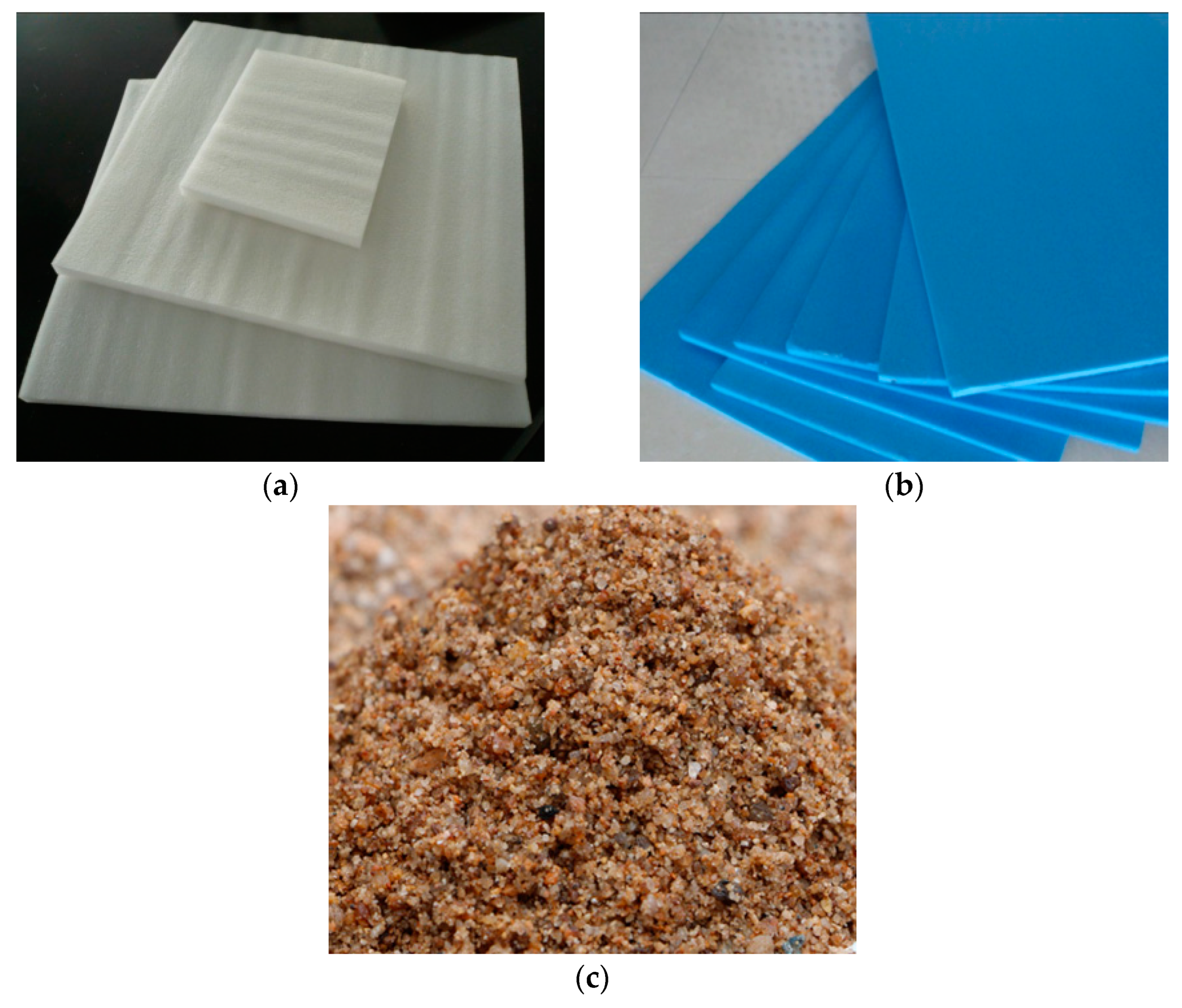
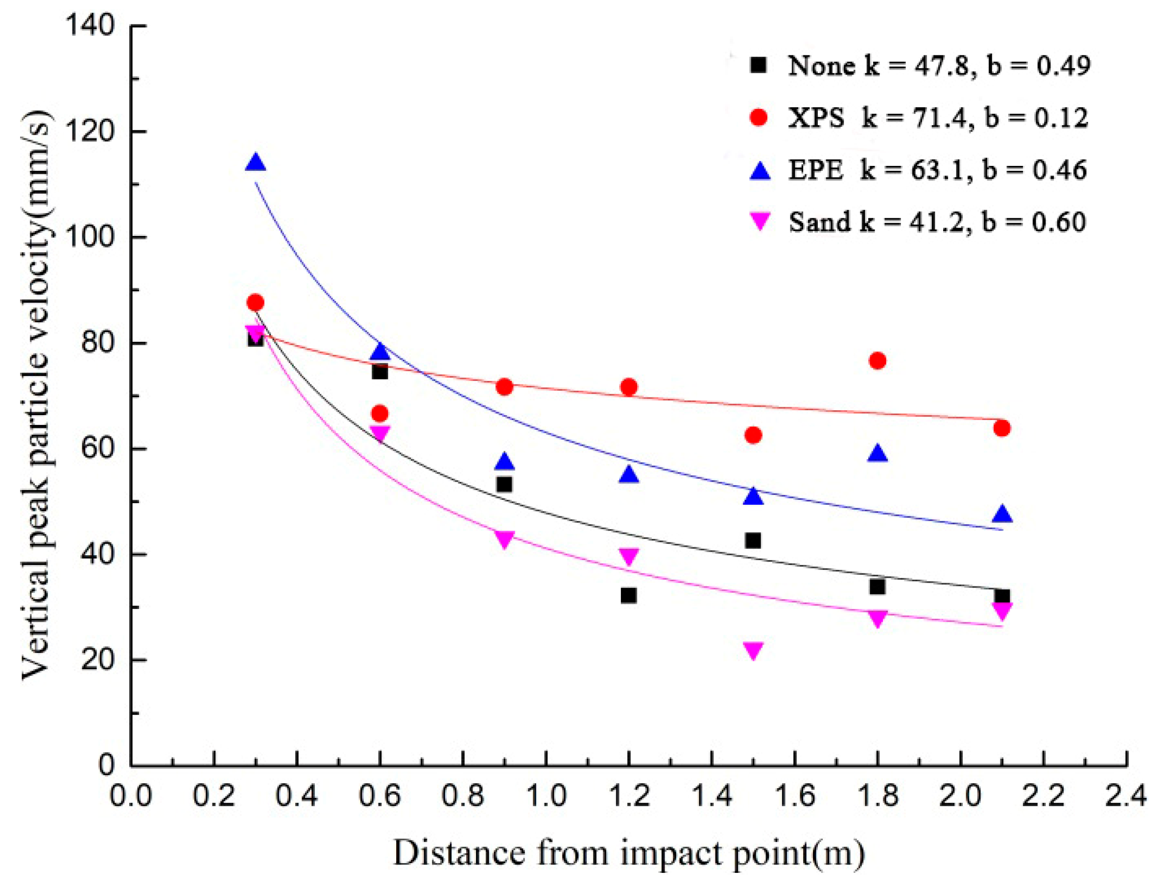
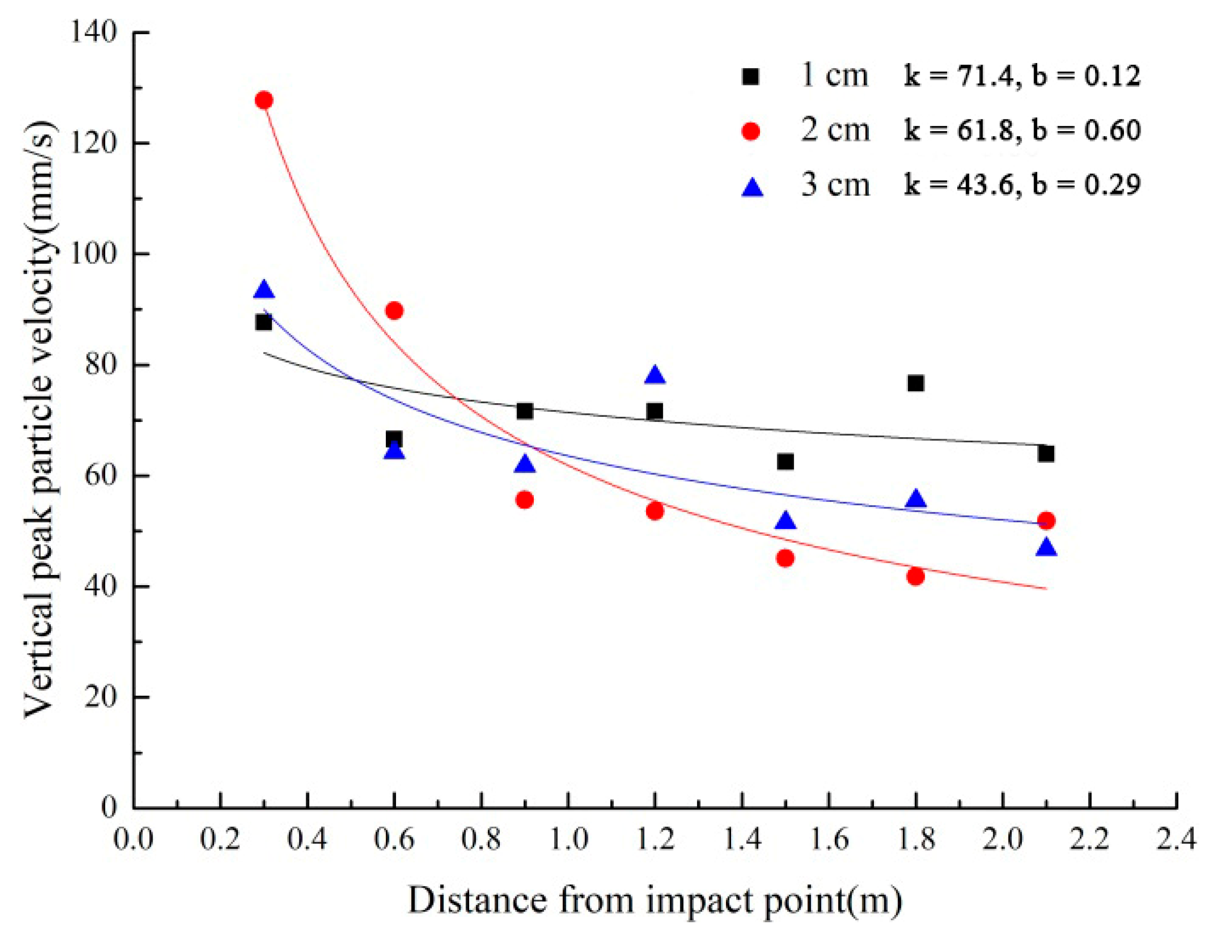
3.3. Dynamic Response Analysis of Multi-Layer Plate Considering Cementing Joints

In the above test, the joint can be regarded as a two-dimensional plane without any thickness. However, the joint is generally presented as an interlayer, such as a clay thin interlayer, in the actual engineering. Not only the wave propagation across the joints but also the properties of the cementing joints, such as wave resistance, elastic modulus, interface roughness, contact area, cementing joint thickness, etc., need to be considered. So, the influence of the different filling materials and thicknesses of cementing joints on the dynamic response of the multi-layer plate are studied.
The filling materials of EPE, XPS, and sand are shown in Figure 13. Figure 14 gives the impact test results of the multi-layer plate, considering a cementing joint with different filling materials, as shown in Figure 13, their thicknesses are all 1 cm. Due to the diversity of the reflection and the transmission of the material, the value of the vertical peak particle velocity and its attenuation law are obviously different. When filled with sand and EPE, the attenuation law of the medium is close, but the value of the vertical peak particle velocity of the sand-filled multi-layer plate is larger. The postponed tendency is no longer apparent when XPS is selected as the filling material, and the value of the attenuation index is only 0.12, though the average value of the vertical peak particle velocity is the largest.
The effect of the cementing joint thickness on the dynamic response of the layered medium was investigated by the double-layer plate impact test. XPS was selected as the filling material of the cementing joint, and the thickness of XPS was set as 1 cm, 2 cm, and 3 cm. As shown in Figure 15, the dynamic response of the double-layer plate varies greatly with the change of the XPS slab’s thickness. When the thickness of the XPS plate is 2 cm, the attenuation law of the vertical peak particle velocity in the horizontal direction is the most obvious, and the curve fitting degree is the highest. The fitting attenuation’s indexes are only 0.12 and 0.29 when the thickness of the XPS plate is 1 cm and 3 cm, respectively. Apparently, the thickness of the cementation layer is the main factor affecting the dynamic response of the layered medium, but there is no regularity between the thickness and the attenuation parameters.

4. Discussion and Conclusions

The influence factors of the dynamic response and attenuation law of the layered medium, such as impact energy, number and thickness of layers and joints, cementing joints materials, etc., are systematically investigated by impact tests of the single-layer plate and the multi-layer plate. The following conclusions are drawn:
(1)
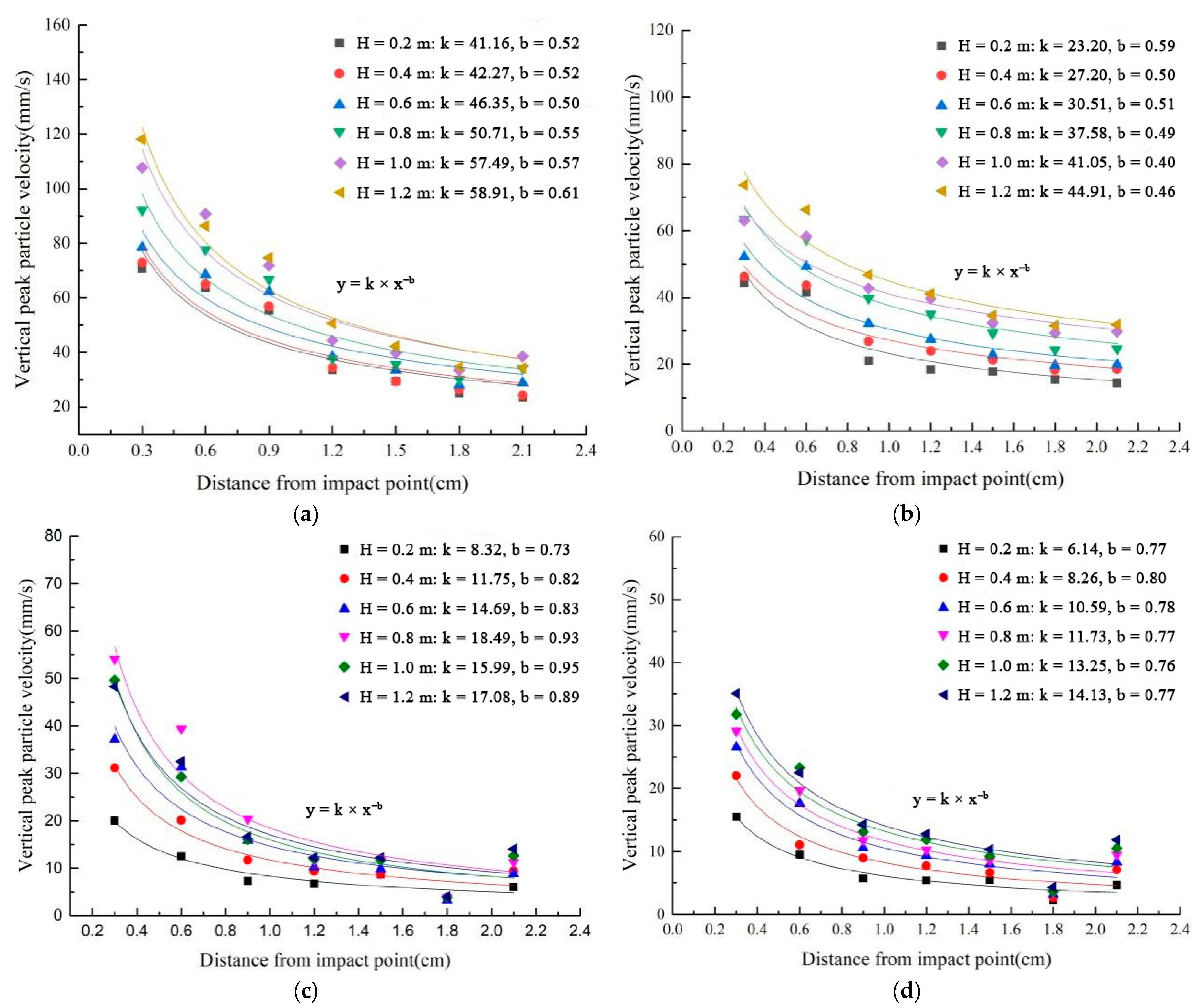
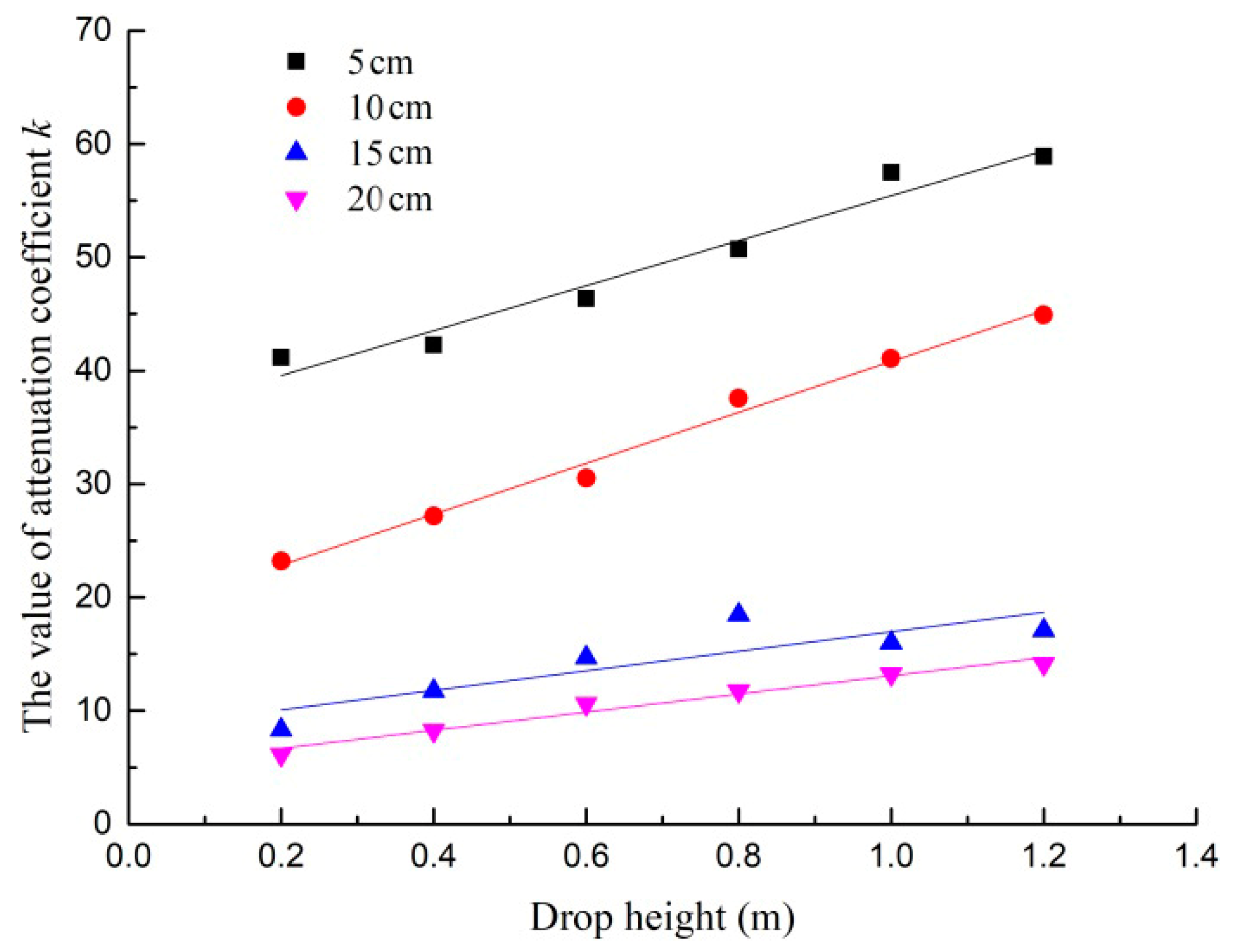
Sadovsky’s empirical formula can fit the attenuation law of the vertical peak particle velocity well, with the ranging in the horizontal direction, and the fitting attenuation’s coefficient k and index b can directly reflect the characteristics of the wave attenuation. The attenuation coefficient k has a linear positive correlation with the impact height under the same plate thickness, while it is negatively correlated with the thickness of the concrete plate under the same impact height.
(2)
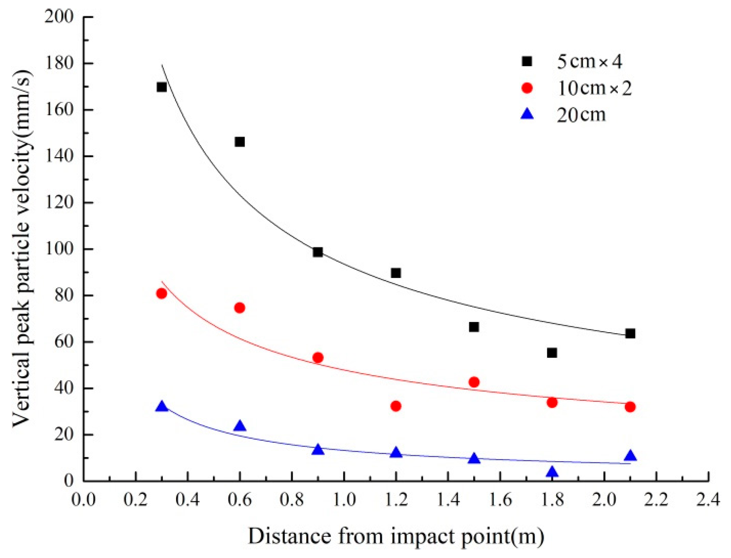
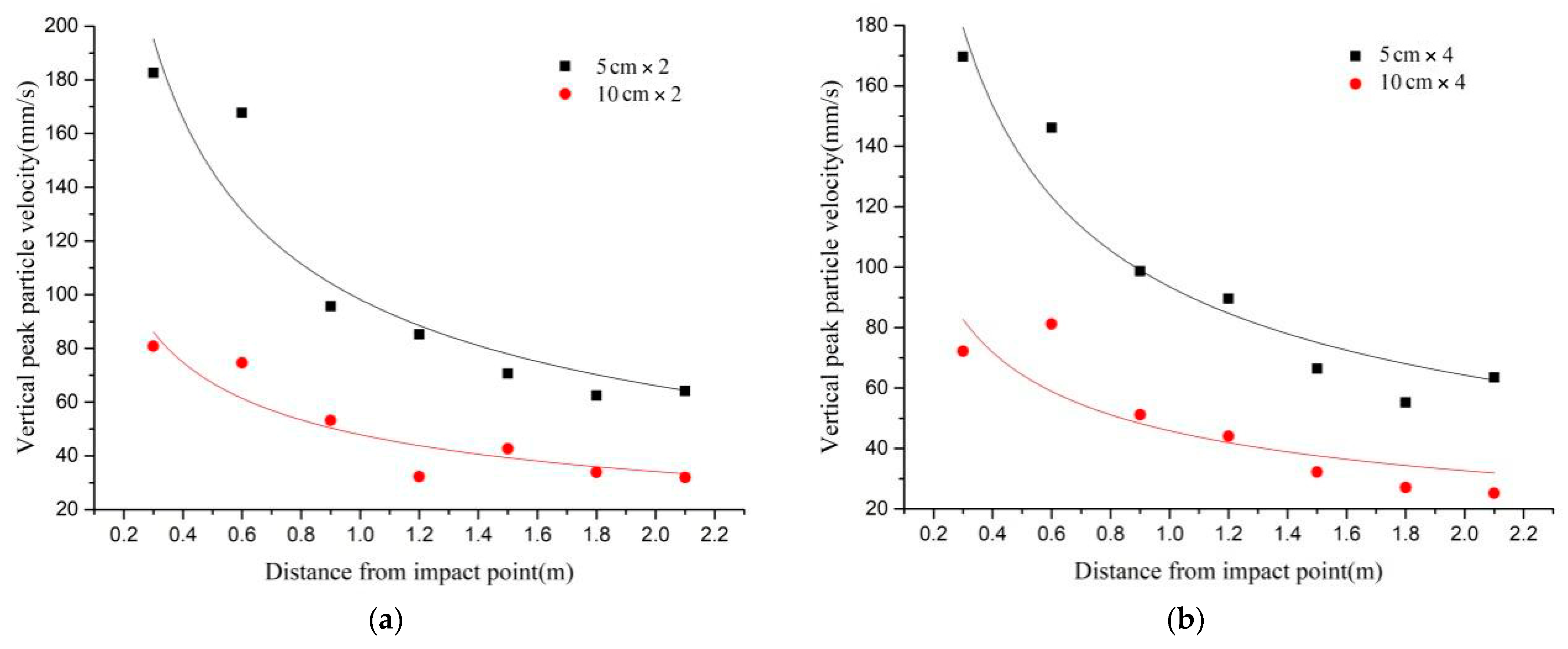
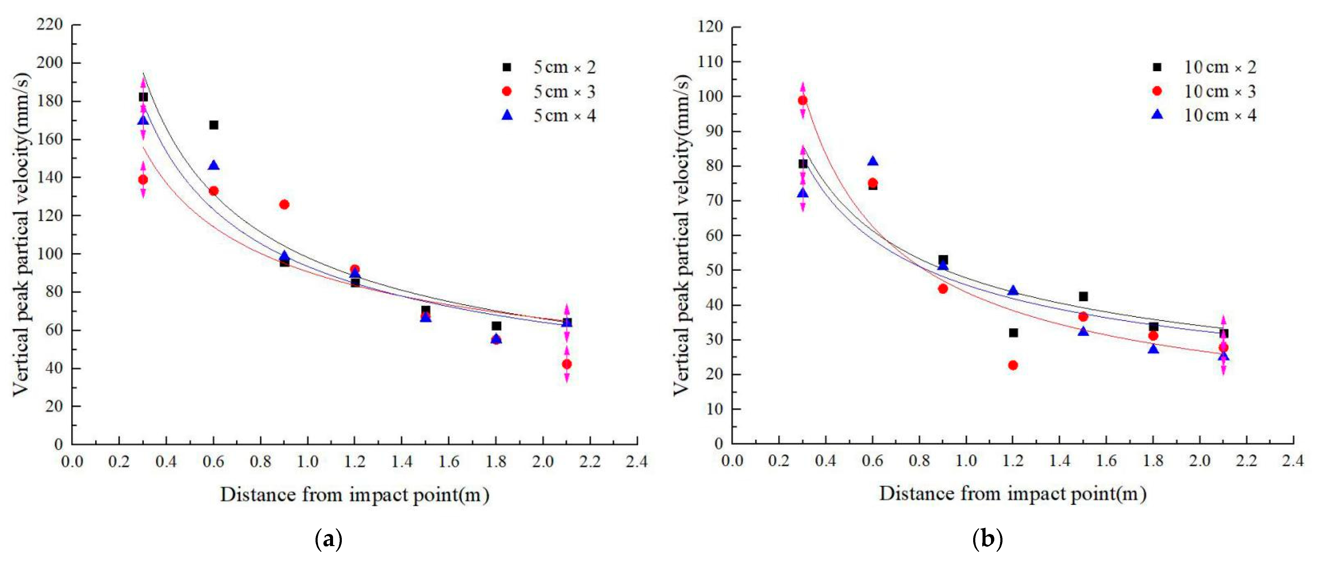
The thickness of the layer is the main factor affecting the dynamic response of the layered medium, so the number of plates and joints and the total thickness of the medium have little influence. The value of the vertical peak particle velocity is larger, and the attenuation law is more obvious, with an increase in the number of layers and a decrease in the thickness of layers under the same total thickness of the layered medium.
(3)
The dynamic response of the multi-layer plate, when considering the cementing joints filled with different materials, varies significantly, and the thickness of the cementing joint has a great influence on the wave propagation of the layered medium. However, the effects of the material and thickness are only presented apparently, so the internal connection and the mechanism between the media and the joint need to be discussed deeply. The properties of the cementing joints and their effects need to be conducted systematically in subsequent studies.

Author Contributions

M.L. designed the study, performed the research, analyzed the data, and wrote the manuscript. Q.G. provided assistance for the data acquisition, data analysis, and statistical analysis. All authors have read and agreed to the published version of the manuscript.

Funding

This research received no external funding.

Institutional Review Board Statement

Not applicable.

Informed Consent Statement

Not applicable.

Data Availability Statement

The data used to support the findings of this study are available from the corresponding author upon request.

Acknowledgments

This work was supported by the Wenzhou Key Laboratory of Intelligent Lifeline Protection and Emergency Technology for Resilient City. In addition, the insightful comments and suggestions from the anonymous reviewers and the editor were sincerely appreciated.

Conflicts of Interest

The authors declare no conflict of interest.

References

  1. Miller, R.K. An Approximate Method of Analysis of the Transmission of Elastic Waves Through a Frictional Boundary. J. Appl. Mech. 1977, 44, 652. [Google Scholar] [CrossRef]
  2. Miller, R.K. The effects of boundary friction on the propagation of elastic waves. Bull. Seismol. Soc. Am. 1978, 68, 987–998. [Google Scholar] [CrossRef]
  3. Schoenberg, M.; Sayers, C.M. Seismic anisotropy of fractured rock. Geophysics 1995, 60, 204–211. [Google Scholar] [CrossRef] [Green Version]
  4. Schoenberg, M. Elastic wave behavior across linear slip interfaces. J. Acoust. Soc. Am. 1980, 68, 1516–1521. [Google Scholar] [CrossRef] [Green Version]
  5. Pyrak-Nolte, L.J.; Myer, L.R.; Cook NG, W. Transmission of seismic waves across single natural fractures. J. Geophys. Res. Solid Earth 1990, 95, 8617–8638. [Google Scholar] [CrossRef]
  6. Pyrak-Nolte, L.J. The seismic response of fractures and the interrelations among fracture properties. Int. J. Rock Mech. Min. Sci. Geomech. Abstr. 1996, 33, 787–802. [Google Scholar] [CrossRef]
  7. Hopkins, D.L.; Myer, L.R.; Cook NG, W. Seismic wave attenuation across parallel fractures as a function of fracture stiffness and spacing. Eos Trans. AGU 1988, 69, 1427–1436. [Google Scholar]
  8. Pyrak-Nolte, L.J.; Myer, L.R.; Cook NG, W. Anisotropy in seismic velocities and amplitudes from multiple parallel fractures. J. Geophys. Res. Solid Earth 1990, 95, 11345–11358. [Google Scholar] [CrossRef]
  9. Chai, S.B.; Li, J.C.; Zhang, Q.B.; Li, H.B.; Li, N.N. Stress wave propagation across a rock mass with two non-parallel joints. Rock Mech. Rock Eng. 2016, 49, 4023–4032. [Google Scholar] [CrossRef]
  10. Zhu, J.B.; Deng, X.F.; Zhao, X.; Zhao, J. A numerical study on wave transmission across multiple intersecting joint sets in rock masses with UDEC. Rock Mech. Rock Eng. 2013, 46, 1429–1442. [Google Scholar] [CrossRef]
  11. Goodman, R.E.; Taylor, R.L.; Brekke, T.L. A model for the mechanics of jointed rock. J. Soil Mech. Found. Div. 1968, 94, 637–659. [Google Scholar] [CrossRef]
  12. Lu, W. A Study on Interaction Between Stress Wave and Slipping Rock Interface. Rock Soil Mech. 1996, 17, 70–75. [Google Scholar]
  13. Li, N.N.; Li, J.C.; Li, H.B.; Liu, T.T.; Chai, S.B. SHPB Experiment on Influence of Contact Area of Joints on Propagation of Stress Wave. Chin. J. Rock Mech. Eng. 2015, 34, 1994–2000. [Google Scholar]
  14. Ju, Y.; Li, Y.; Xie, H.; Song, Z.; Tian, L. Stress Wave Propagation and Energy Dissipation in Jointed Rocks. Chin. J. Rock Mech. Eng. 2006, 25, 2426–2434. [Google Scholar]
  15. Gu, B.; Suárez-Rivera, R.; Nihei, K.T.; Myer, L.R. Incidence of plane waves upon a fracture. J. Geophys. Res. Solid Earth 1996, 101, 25337–25346. [Google Scholar] [CrossRef]
  16. Gu, B.; Nihei, K.T.; Myer, L.R.; Pyrak-Nolte, L.J. Fracture interface waves. J. Geophys. Res. Solid Earth 1996, 101, 827–835. [Google Scholar]
  17. Cai, J.G.; Zhao, J. Effects of multiple parallel fractures on apparent attenuation of stress waves in rock masses. Int. J. Rock Mech. Min. Sci. 2000, 37, 661–682. [Google Scholar]
  18. Zhao, J.; Zhao, X.B.; Cai, J.G. A further study of P-wave attenuation across parallel fractures with linear deformational behaviour. Int. J. Rock Mech. Min. Sci. 2006, 43, 776–788. [Google Scholar]
  19. Zhao, J.; Cai, J.G.; Zhao, X.B.; Li, H.B. Experimental study of ultrasonic wave attenuation across parallel fractures. Geomech. Geoengin. Int. J. 2006, 1, 87–103. [Google Scholar] [CrossRef]
  20. Zhao, J.; Cai, J.G. Transmission of elastic P-waves across single fractures with a nonlinear normal deformational behavior. Rock Mech. Rock Eng. 2001, 34, 3–22. [Google Scholar] [CrossRef]
  21. Wang, Q.Z.; Zhang, S.; Xie, H.P. Rock dynamic fracture toughness tested with holed-cracked flattened Brazilian discs diametrically impacted by SHPB and its size effect. Exp. Mech. 2010, 50, 877–885. [Google Scholar] [CrossRef]
  22. Lu, F.; Lin, Y.; Wang, X.; Lu, L.; Chen, R. A theoretical analysis about the influence of interfacial friction in SHPB tests. Int. J. Impact Eng. 2015, 79, 95–101. [Google Scholar] [CrossRef]
  23. Li, J.C.; Li, N.N.; Li, H.B.; Zhao, J. An SHPB test study on wave propagation across rock masses with different contact area ratios of joint. Int. J. Impact Eng. 2017, 105, 109–116. [Google Scholar] [CrossRef]
  24. Yang, Y.; Yang, R.S.; Wang, J.G. Simulation Material Experiment on Dynamic Mechanical Properties of Jointed Rock Affected by Joint Thickness. J. China Univ. Min. Technol. 2016, 45, 21–26. [Google Scholar]
  25. Wang, W.; Li, K.; Yan, Z.; Tang, X. Study on the Closure Deformation Properties of Joint Fractal under SHPB Load. Gold Sci. Technol. 2017, 25, 75–83. [Google Scholar]
  26. Challita, G.; Othman, R. Finite-element analysis of SHPB tests on double-lap adhesive joints. Int. J. Adhes. Adhes. 2010, 30, 236–244. [Google Scholar] [CrossRef] [Green Version]
  27. Tian, Z.N.; Li, S.H.; Xiao, N. Experimental Studies and Numerical Simulation of Stress Wave Propagation in One-dimensional Rock Mass. Chin. J. Rock Mech. Eng. 2008, 27, 2687–2693. [Google Scholar]
  28. Sun, B.; Guo, S.S.; Zeng, S.; Ma, A.Y.; Deng, X.S. Transmission and Reflection and the Attenuation Law of Stress Wave in Layered Joint Rock Mass. J. Disaster Prev. Mitig. Eng. 2015, 35, 828–832. [Google Scholar]
  29. Peng, F.H.; Li, S.L.; Cheng, J.Y. Experimental study on characteristics of stress wave propagation in mesoscale and complex rock mass by microseismic monitoring. Chin. J. Geotech. Eng. 2014, 36, 312–319. [Google Scholar]
  30. Wang, Z.J.; Li, X.L.; Ge, L.; Wang, P.Y. Free-field stress wave propagation induced by underground chemical explosion in granite. Chin. J. Rock Mech. Eng. 2003, 22, 1827–1831. [Google Scholar]
  31. Ghaboussi, J.; Wilson, E.L.; Isenberg, J. Finite element for rock joints and interfaces: 11F, 8R. J. SOIL MECH. FOUND. DIV. V99, SM10, 1973, P833–848. Int. J. Rock Mech. Min. Sci. Geomech. Abstr. 1974, 11, 66. [Google Scholar]
  32. Schwer, L.E.; Lindberg, H.E. A finite element slideline approach for calculating tunnel response in jointed rock. Int. J. Numer. Anal. Methods Geomech. 1992, 16, 529–540. [Google Scholar] [CrossRef]
  33. Coates, R.T.; Schoenberg, M. Finite difference modelling of faults and fractures. Geophysics 1994, 60, 1514–1526. [Google Scholar] [CrossRef] [Green Version]
  34. Fan, S.C.; Jiao, Y.Y.; Zhao, J. On modelling of incident boundary for wave propagation in jointed rock masses using discrete element method. Comput. Geotech. 2004, 31, 57–66. [Google Scholar] [CrossRef]
  35. Cundall, P.A. A computer model for simulating progressive, large-scale movements in blocky rock systems. In Proceedings of the International Symposium on Rock Mechanics, Nancy, France, 4–6 October 1971; Volume 1, pp. 11–18. [Google Scholar]
  36. Brady, B.H.; Hsiung, S.H.; Chowdhury, A.H.; Philip, J. Verification studies on the UDEC computational model of jointed rock. In Proceedings of the International Conference on Mechanics of Jointed and Faulted Rock, Vienna, Austria, 18–20 April 1990; pp. 551–558. [Google Scholar]
  37. Zhao, X.; Zhao, J.; Cai, J.; Hefny, A.M. UDEC modelling on wave propagation across fractured rock masses. Comput. Geotech. 2008, 35, 97–104. [Google Scholar] [CrossRef]
  38. Zhao, G.F.; Zhao, J. Microscopic Numerical Modelling of the Dynamic Strength of Brittle Rock. In Proceedings of the International Conference on Analysis of Discontinues Deformation: New Developments & Applications, Singapore, 25–27 November 2010. [Google Scholar]
  39. Deng, X.F.; Zhu, J.B.; Chen, S.G.; Zhao, J. Some Fundamental Issues and Verification of 3DEC in Modeling Wave Propagation in Jointed Rock Masses. Rock Mech. Rock Eng. 2012, 45, 943–951. [Google Scholar] [CrossRef] [Green Version]
  40. Zhu, J.B.; Zhao, G.; Zhao, X.; Zhao, J. Validation study of the distinct lattice spring model (DLSM) on P-wave propagation across multiple parallel joints. Comput. Geotech. 2011, 38, 298–304. [Google Scholar] [CrossRef]
Figure 1. Calculation model of concrete slab impacted by drop hammer.
Coatings 12 01474 g001
Figure 2. The stress cloud diagram at different moments: (a) t = 9.983 × 10⁻² ms; (b) t = 2.9977 × 10⁻² ms; (c) t = 1.2996 ms.
Coatings 12 01474 g002
Figure 3. Attenuation of vertical and radial peak particle velocity with distance on concrete surface.
Coatings 12 01474 g003
Figure 4. Mold making and steel binding.
Coatings 12 01474 g004
Figure 5. Specimens casting.
Coatings 12 01474 g005
Figure 6. Schematic diagram of measurement point arrangement.
Coatings 12 01474 g006
Figure 7. JM5938 dynamic signal test and analysis system.
Coatings 12 01474 g007
Figure 8. The attenuation law of the vertical peak particle velocity of different thicknesses of concrete slabs: (a) 5 cm; (b) 10 cm; (c) 15 cm; (d) 20 cm.
Coatings 12 01474 g008
Figure 9. The change of the attenuation coefficient k of the vertical peak particle velocity with impact height under different thicknesses of concrete slabs.
Coatings 12 01474 g009
Figure 10. The impact test under the same thickness of layered medium and different number of slabs.
Coatings 12 01474 g010
Figure 11. The impact test under the same number but different thicknesses of slabs: (a) 5 cm layer thickness double-layer plate and 10 cm layer thickness double-layer plate; (b) 5 cm layer thickness four-layer plate and 10 cm layer thickness four-layer plate.
Coatings 12 01474 g011
Figure 12. The impact test under the same thickness but different numbers of slabs: (a) 5 cm layer thickness multi-layer plate; (b) 10 cm layer thickness multi-layer plate.
Coatings 12 01474 g012
Figure 13. Different cementing joint filling materials: (a) EPE; (b) XPS; (c) sand.
Coatings 12 01474 g013
Figure 14. Dynamic response of double-layer plate with different filling materials.
Coatings 12 01474 g014
Figure 15. The dynamic response of double-layer plate with different cementing joint thicknesses.
Coatings 12 01474 g015
Table 1. The parameters of materials.
Concrete SlabDrop Hammer
Density (kg/m3)Compressive Strength (MPa)Aggregate Size (m)Density (kg/m3)Elasticity Modulus (GPa)Yield Strength (MPa)
2.35 × 10323.50.018.32 × 103200400
Table 2. Type and size of concrete slab.
TypeSize (cm × cm × cm)Number
B1250 × 100 × 54
B2250 × 100 × 104
B3250 × 100 × 151
B4250 × 100 × 201
Table 3. The fitting parameters of the vertical peak particle velocity attenuation curve under different test conditions.
ParametersSingle-Layer PlateDouble-Layer PlateTriple-Layer PlateFour-Layer Plate
10 cm15 cm20 cm5 cm × 210 cm × 25 cm × 310 cm × 35 cm × 410 cm × 4
k41.116.013.298.247.990.743.793.545.8
b0.400.950.760.570.490.450.700.540.49
Publisher’s Note: MDPI stays neutral with regard to jurisdictional claims in published maps and institutional affiliations.

