Article

Protective Cr Coatings with ZrO2/Cr Multilayers for Zirconium Fuel Claddings

by
Dmitrii Vladimirovich Sidelev
1,*,
Sergey Evgeneyvich Ruchkin
1,
Ivan Andreevich Shelepov
2,
Nikolay Sergeevich Saburov
2,
Andrey Gennadievich Malgin
2,
Kirill Konstantinovich Polunin
3,
Kirill Vicheslavovich Stoykov
3 and
Andrey Andreevich Mokrushin
3
1
School of Nuclear Science & Engineering, Tomsk Polytechnic University, 30 Lenina Av., 634050 Tomsk, Russia
2
SC «VNIINM», 5a Rogova St., 123098 Moscow, Russia
3
LUCH JSC, 24 Zheleznodorozhnaya St., 142103 Podolsk, Russia
*
Author to whom correspondence should be addressed.
Coatings 2022, 12(10), 1409; https://doi.org/10.3390/coatings12101409
Submission received: 1 September 2022 / Revised: 16 September 2022 / Accepted: 21 September 2022 / Published: 27 September 2022
(This article belongs to the Special Issue Protective Composite Coatings: Implementation, Structure, Properties)

Abstract

:
This article described the protective properties of Cr coatings with a barrier layer composed of ZrO2/Cr multilayers deposited onto E110 zirconium alloy. The coatings with a ZrO2/Cr multilayer thickness of 100, 250, and 750 nm and single-layer (1.5 µm) ZrO2 barrier were obtained by multi-cathode magnetron sputtering in Ar + O2 atmosphere. Then, cracking resistance and oxidation behavior were studied under conditions of thermal cycling (1000 °C) in air and high-temperature oxidation at 1200–1400 °C in a water steam. The role of the ZrO2/Cr multilayers and multilayer thickness on cracking resistance of the experimental coatings and oxidation resistance of the coated E110 alloy was discussed. It was shown that the coatings with more quantity of the ZrO2/Cr multilayers have higher cracking resistance, but such types of samples have a large amount of coating spallation under thermal cycling. The high-temperature steam oxidation (1200–1400 °C) demonstrated that interfaces of the ZrO2/Cr multilayers can act as a source of cavities formed by the Kirkendall mechanism that results in accelerating Cr–Zr interdiffusion for Cr-coated E110 alloy.

1. Introduction

Chromium coatings are considered as a protective barrier of nuclear fuel claddings made from zirconium alloys under normal and accidental conditions [1,2,3]. The selection of Cr is caused by forming an outer dense oxide (Cr2O3) scale, which can act as a barrier for oxygen penetration into Zr alloy claddings under the conditions of pressurized water (~360 °C, 186 atm) and in a water steam at high temperatures [4,5,6]. Brachet et al. [1] showed the possibility to protect Zr alloy for a long time by deposition of 10–15 µm-thick Cr coatings. Nevertheless, Cr-coated Zr alloys have a significant drawback, which becomes critical at the temperature of ~1200–1250 °C and higher. When the temperature of Zr-based elements reaches 900 °C, the phase transition of Zr alloys from the α (hexagonal closed-packed) to the β (body centered cubic) phase will occur. This causes the increase of a diffusion coefficient of Cr in Zr alloys that leads to a growth of a Zr–Cr eutectic layer with a melting temperature of ~1332 °C [7,8]. Thereby, much attention is warranted to find barrier materials for Cr coatings to prevent Cr–Zr interdiffusion at high temperatures. Up to now, a lot of candidate materials have been studied such as metals (Mo, Ta, etc.) [9,10,11] and compounds (Al2O3, TiN, CrN, ZrO2, etc.) [12,13,14]. Krejci et al. showed high protective and barrier properties of CrN interlayer for Cr–Zr system at high-temperature oxidation [14]. Wang et al. [12] demonstrated the prevention of oxygen diffusion into the Cr-coated Zr alloy using the ZrO2 barrier. The possibility to limit of high-temperature interdiffusion between FeCrAl coating and Zr alloy is shown in ref. [13]. Pan et al. suggested the use of a ZrO2/Cr bilayer coating for the protection of Zr-4 alloy [15]. Yun et al. [16] investigated the oxidation mechanism of Cr coating with CrN/TiSiN interlayer and found that the oxides formed at the coating/alloy interface cannot inhibit outward diffusion of zirconium, resulting in coating spallation and cracking. Thermal shock testing of TiN/Cr-coated zirconium alloy showed forming cracks and a large number of pores, resulting in poor protection of the alloy at high temperatures [17].
The compound layers have better barrier performance than metals, but their cracking resistance is low due to different mechanical properties (hardness and elastic modulus) in comparison with Cr and Zr. Earlier, it was shown that metal/compound multilayers can be favorable to use as a barrier for Cr–Zr system [14,18]. Multilayer barriers can be more resistant to cracking under high-temperature ramps than that of single-layer compound barriers. In situ XRD studies [19,20] revealed that CrN/Cr multilayers can prevent a growth of the interdiffusion Cr–Zr layer up to 1400 °C as well as that Cr coatings with CrN/Cr multilayers have higher resistance to cracking when the thickness of the CrN/Cr multilayers decreased from 750 to 100 nm. Superior oxidation resistance of multilayer Cr/CrN coatings was also found in a water steam (1200 °C) and in thermal shock tests (900–1200 °C) [21,22]. Apart from the CrN/Cr multilayers, other candidates (e.g., ZrO2) should be considered as the barrier material for preventing Cr–Zr interdiffusion. However, studies have described corrosion behavior of the coatings with the single-layer barrier based on ZrO2 at a maximal temperature of 1100 °C. Moreover, there are no published data about the role of the multilayer structure of the barrier based on ZrO2 on cracking resistance and the oxidation behavior of Cr-coated Zr alloys. Therefore, this study aimed to determine the protective properties of Cr coatings with a barrier from ZrO2/Cr multilayers deposited onto Zr alloy in the range of 1000–1400 °C.

2. Experimental Details

2.1. Sample Preparation

Experimental coatings were deposited using the vacuum ion–plasma installation with a multi-cathode magnetron sputtering system, which is described in ref. [4]. The E110 (0.9–1.1 wt% Nb, 0.06–0.1 wt% O and Zr balance) zirconium alloy plates (15 mm × 15 mm × 2 mm) and fuel claddings (outer and inner diameters of 9.1 and 7.9 mm) were used as substrates. The plates were grinded and polished using a SiC sandpaper (P2500), then they were rinsed in an ultrasonic bath with acetone and dried by air for 2 min. Up to the coating process, all substrates were bombarded by Ar ions using an ion source with a closed electron drift for 20 min. The substrates were planetary rotated during the ion etching and coating deposition for uniform surface treatment of the samples. The quartz thickness gauge Micron-5 (Izovac Ltd., Minsk, Belarus) was used to determine the deposition rates of ZrO2 and Cr multilayers. Four series of the samples were prepared and their deposition conditions are listed in Table 1. Scanning electron microscopy (SEM, JEOL JSM 7500F, Tokyo, Japan) in an operation mode of secondary electrons was used to control the thickness of the ZrO2/Cr multilayers. This analysis was carried out using the equipment of the CSU NMNT TPU, supported by the RF MES project #075-15-2021-710.
The sample with the single-layer ZrO2 barrier (1.5 µm) and outer 9.5 µm-thick Cr layer was also obtained for comparison. Other coating series have barriers composed of ZrO2/Cr multilayers and outer Cr layers with total thicknesses of 3 and 7 µm, respectively. The Cr coatings with the ZrO2/Cr multilayers are further tilted as the “ZrO2/Cr-thickness (in nm)” coatings in this article. The E110 alloy samples with the single-layer Cr coating was also used from a previous study [18] for comparison.

2.2. Thermal Cycling

The thermal cycling of the samples was performed in air at normal pressure (1 atm). Two different series of the thermal cycling were selected to identify cracking resistance and oxidation behavior of the samples. The first series was a short-term cycling, which included only 4 cycles. The long-term cycling was composed of 50 cycles. Each thermal cycle included two stages. In the first stage, the samples were loaded in the furnace at the temperature of 1000 °C and then kept for 2 min. TIn the second stage, the samples were unloaded from the furnace and cooled for 3 min. The weight of the samples was measured every 5 cycles in the case of the long-term thermal cycling.

2.3. High-Temperature Oxidation in a Water Steam

The plates and fuel claddings were oxidized in a water steam at 1200 and 1250–1400 °C, respectively. The oxidation tests at 1200 °C were carried out in accordance with the U.S. NRC guideline [23] by a LOCA345 test facility (SC VNIINM, Moscow, Russia). Firstly, the samples were kept in the cold zone (300 °C) for 300 s, then they were transited to the hot zone of the furnace and heated to 1200 ± 3 °C with a heating rate of ~20 °C/s. The flow rate of water steam was equal to ~4.0 mg/cm2. After the oxidation, the samples were immediately quenched into distilled water. The durations of these tests were equal to 1000 and 2000 s.
The second type of steam oxidation tests was performed at the temperature of 1250, 1330 and 1400 °C using a GASPAR facility [24] in JSC LUCH (JSC LUCH, Podolsk, Russia). The mass flow of water steam and heating rates were equal to 40 mg/s and 33 °C/s, respectively. After the oxidation, the samples were transited to the cold zone and to cool they up to 900 °C in a water steam with a cooling rate of 20 °C/s. After it, the samples were immediately quenched into a distilled water.

2.4. Sample Characterization

The weight gain of the samples due to their oxidation was measured by a balance Sartorius CP124S (Goettingen, Germany). The cross-sections of the samples were investigated by optical microscopy (AXIOVERT 200MAT, Zeiss, Jena, Germany) before and after the oxidation tests. The depth distributions of Cr, Zr, and O in the samples were determined using a glow discharge optical emission spectroscopy (GDOES, GD-Profiler 2, Horiba Scientific, Kyoto, Japan). The cross-section and surface microstructure, elemental compositions of the samples were studied by a scanning electron microscope (SEM) Vega 3 (Tescan, Brno, Czech Republic) equipped with an energy-dispersive X-ray spectroscopy (EDX) attachment.

3. Results

3.1. The As-Prepared Coatings

Figure 1 and Figure 2 show the cross-section microstructure of the E110 alloy plates with the ZrO2/Cr coatings and the elemental (Cr, Zr, and O) depth distributions in the coatings obtained by optical microscopy and GDOES, respectively.
According to Figure 1 and Figure 2, the ZrO2/Cr-250 sample had a 7 µm-thick outer Cr layer and a ZrO2/Cr barrier which was between the Cr layer and E110 alloy. This barrier layer was composed of twelve alternate ZrO2 and Cr multilayers with a multilayer thickness of ~250 nm. The total thickness of the ZrO2/Cr-250 coating was 10.2 ± 0.3 µm. The ZrO2/Cr-100 and ZrO2/Cr-750 samples had 30 and 4 multilayers with a multilayer thickness of ~100 and 750 nm, respectively. The ZrO2/Cr coating had a single-layer ZrO2 barrier (~1.5 µm) and outer Cr layer with a thickness of ~8.5 µm. The total thickness of all coatings was equal to 10.1 ± 0.4 µm.
The experimental coatings had a uniform total thickness over their cross-sections and smooth interfaces between the coating material and zirconium alloy according to the cross-section optical images and elemental depth profiles.

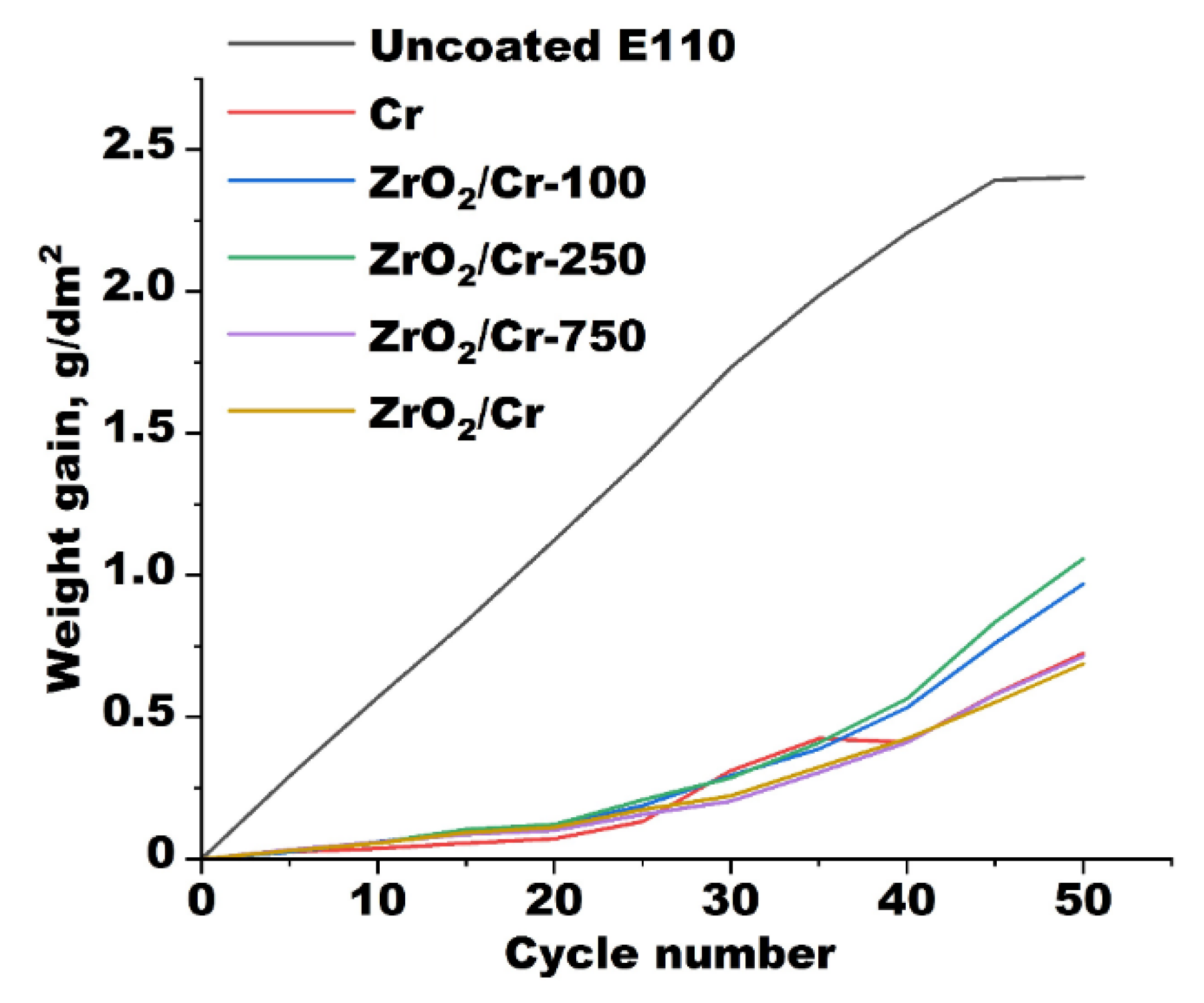
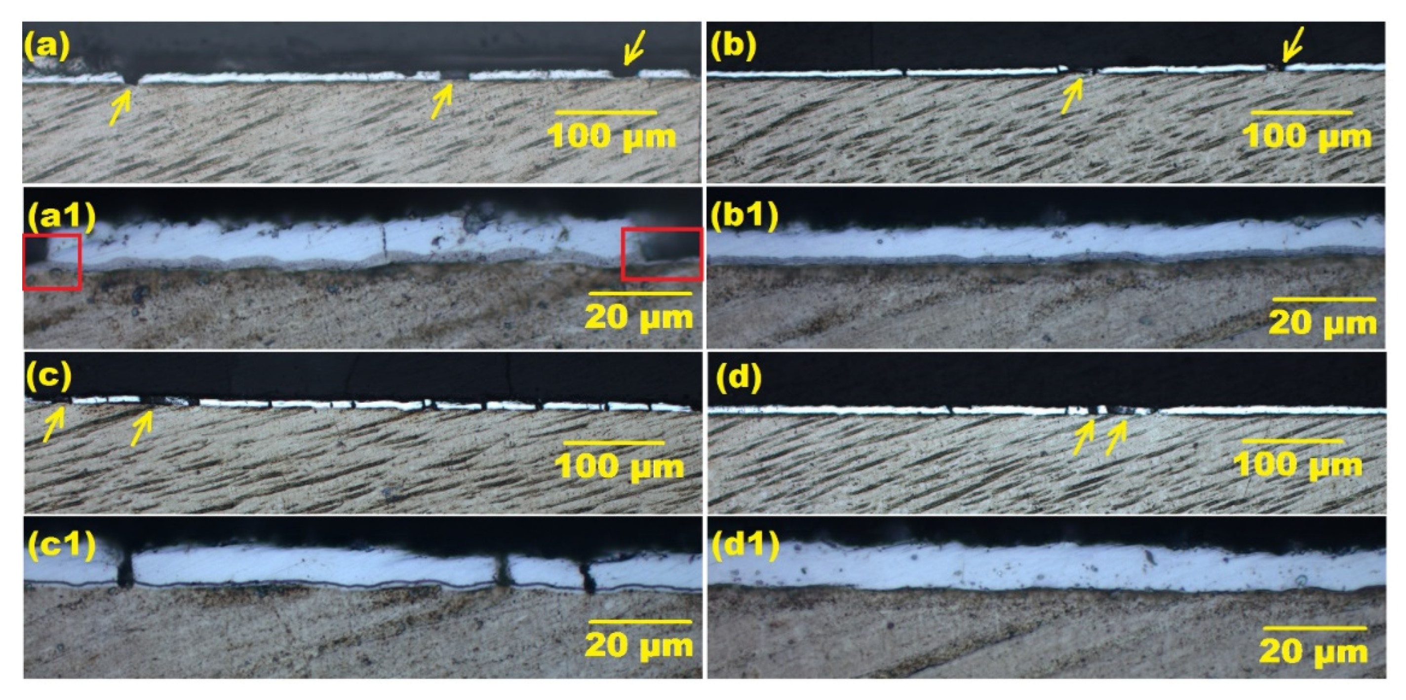
3.2. Thermal Cycling

Figure 3 presents the weight gains of the uncoated and the coated E110 alloy samples during the long-term thermal cycling at 1000 °C.
The deposition of the ZrO2/Cr coatings onto the E110 alloy plates resulted in a strong decrease of the weight gain in comparison with the uncoated one. The weight gains of the samples with ZrO2/Cr coatings were the same up to 10 cycles (~0.06 g/dm2), then became different. Based on Figure 3, the weight gains of the samples with the ZrO2/Cr-100 and ZrO2/Cr-250 coatings (~1.0 g/dm2) were higher than those of the samples with the ZrO2/Cr-750 and ZrO2/Cr coatings (~0.7 g/dm2) after 50 cycles. The E110 alloy sample with a single-layer Cr coating had the same weight gain as the ZrO2/Cr-750 and ZrO2/Cr samples [18]. To identify a difference in weight gains of the samples, their cross-section microstructures were examined by optical microscopy and SEM after thermal cycling (Figure 4, Figure 5 and Figure 6).
The vertical cracks in the coatings and coating spallation were well observed in the cross-sections of all samples. These cracks formed at the coating/alloy and multilayer interfaces, then they propagated vertically to the outer surface. The coating spallation could occur both at the coating/alloy and multilayer interfaces, which was well observed and is shown in Figure 4a1.
The quantity of cracks and coating spallation in the samples is dependent on multilayer structure of the coatings. It was well observed that the ZrO2/Cr-100 sample had a high quantity of the coating spallation, while the ZrO2/Cr-750 sample had a lot of cracks inside the coating. The linear density of cracks (Lc) and spallation (Ls) were calculated using optical images of the cross-sections of the samples after the short-term thermal cycling:
L c = N c l ,
L S = N s l ,
where Nc—total number of cracks in the coatings; Ns—total number of coating spallation; l—total length of the cross-section using for calculation of cracks and coating spallation (in mm). More than 10 optical images were used for each sample to determine their Lc and Ls parameters (Table 2). These parameters were also calculated for the Cr-coated E110 alloy sample studied in a previous paper [18].
It was found that the ZrO2/Cr-100 sample had the lowest value of Lc (2.1 mm−1). It was even lower than that of the sample with the Cr coating (4.6 mm−1) [18]. However, the linear density of coating spallation was the highest for this sample (5.0 mm−1) among other samples. Moreover, the Lc and Ls parameters were dependent on the thickness of the ZrO2/Cr multilayers. As the multilayer thickness changed from 100 to 750 nm, the values of Lc and Ls parameters increased from 2.1 to 15.1 mm−1 and decreased from 5.0 to 2.2 mm−1, respectively. These data indicates higher resistance to cracking of the coating with the thinnest (100 nm) ZrO2/Cr multilayers in comparison with the ZrO2/Cr-250 and ZrO2/Cr-750 samples. Nevertheless, the ZrO2/Cr-100 sample had a low resistance to coating spallation during thermal cycling among other experimental samples. This is due to a higher quantity of the interfaces between the ZrO2/Cr multilayers (30 multilayers) than in other cases.
The different resistance to cracking and coating spallation of the experimental coatings led to different oxidation of the samples during the thermal cycling. Figure 5 presents the cross-section microstructure of the ZrO2/Cr-100 sample after 50 thermal cycles. Two typical regions of the alloy oxidation were found. When the ZrO2/Cr-100 coating cracked, the area of the alloy oxidation was relatively small (Figure 5b). However, the area of the alloy oxidation became noticeably higher in the case of coating spallation. Due to this, the ZrO2/Cr-100 and ZrO2/Cr-250 samples have higher weight gains than other samples as they have higher values of Ls.
The ZrO2/Cr-750 sample had higher Lc than that of the samples with the single-layer Cr and ZrO2/Cr coatings, but all these samples had the same weight gain. Based on the EDS maps (Figure 6), the ZrO2/Cr-750 coating was adherent to the alloy even in the case of coating cracking. Thereby, such a coating can protect the alloy interface in the region of cracks and the alloy oxidation will be not as fast as that in the case of coating spallation.

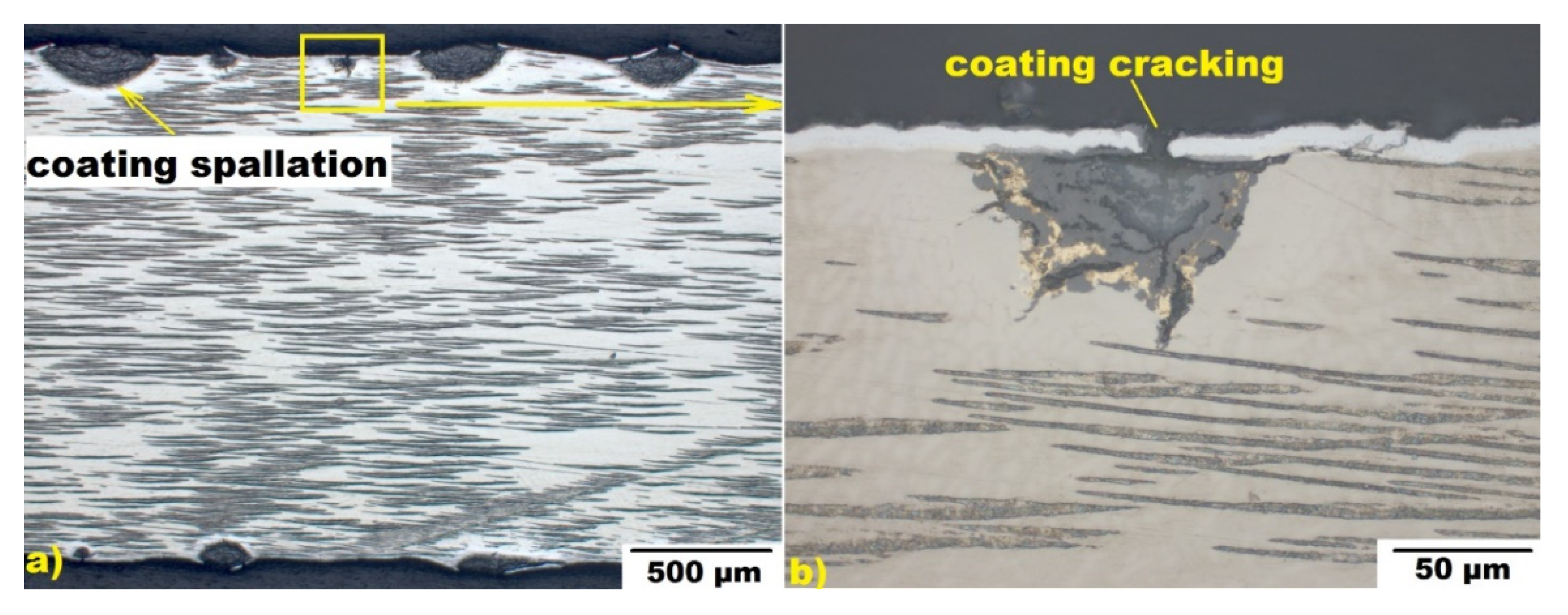
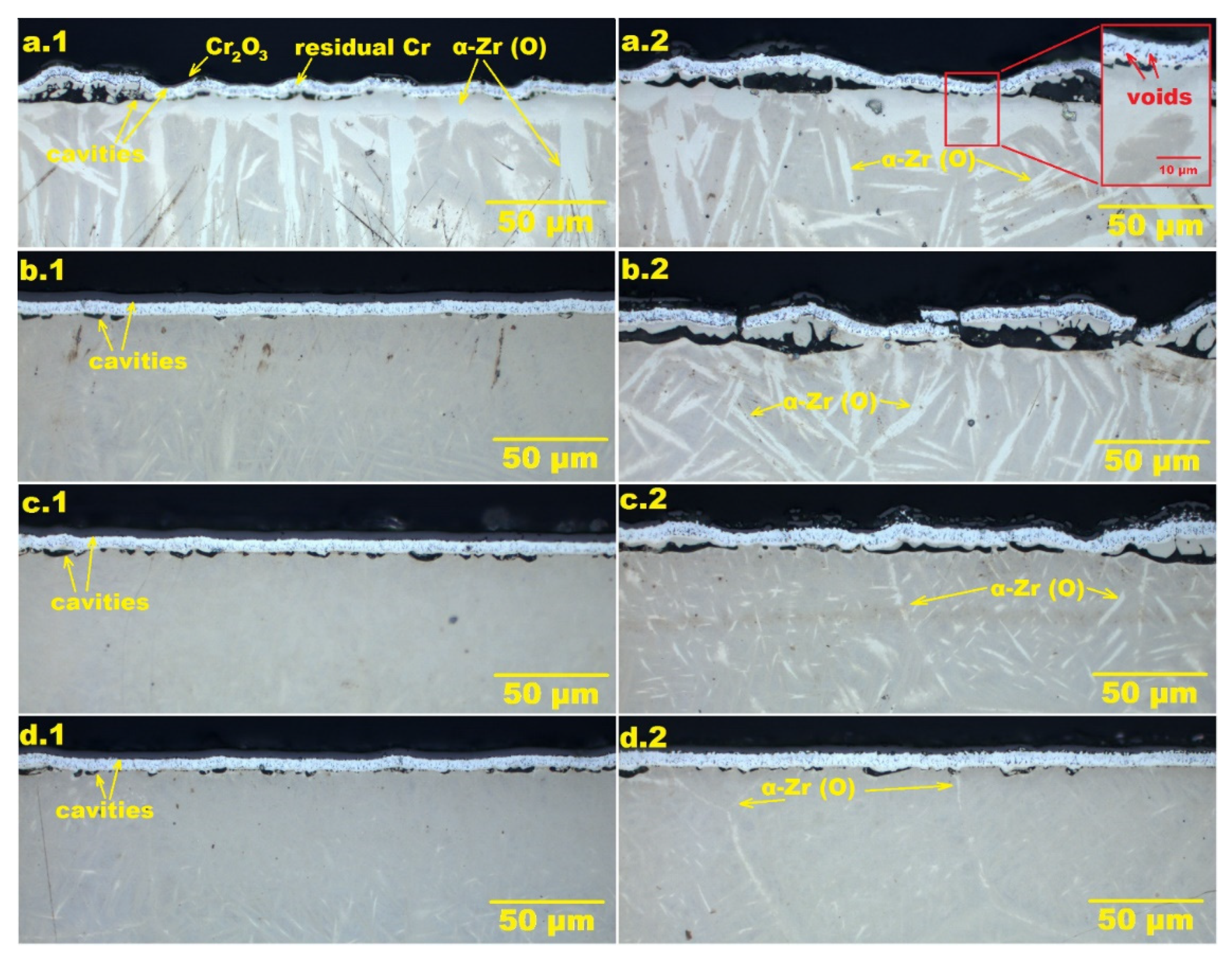
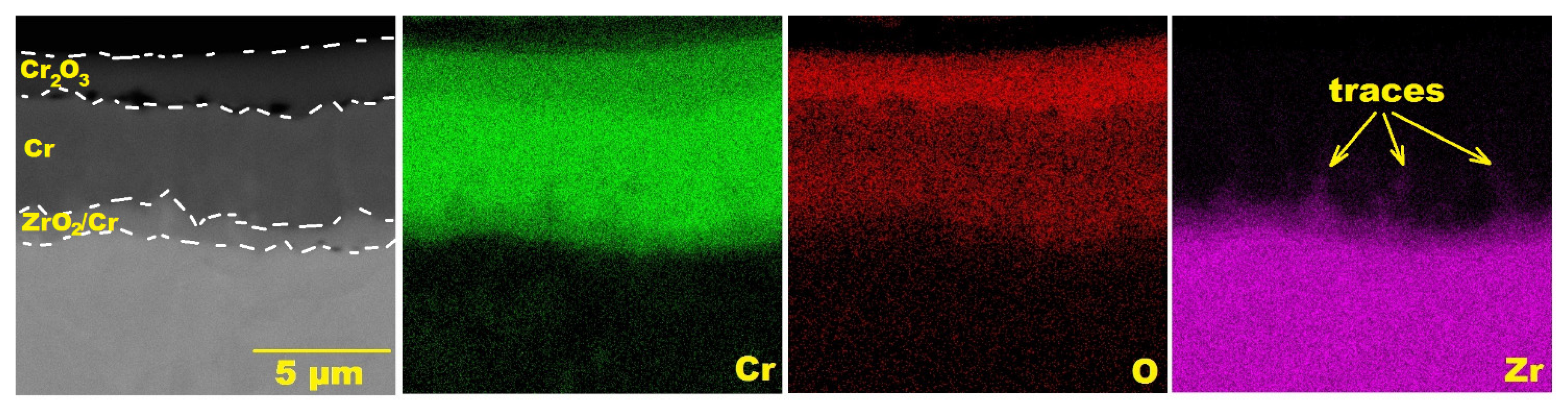
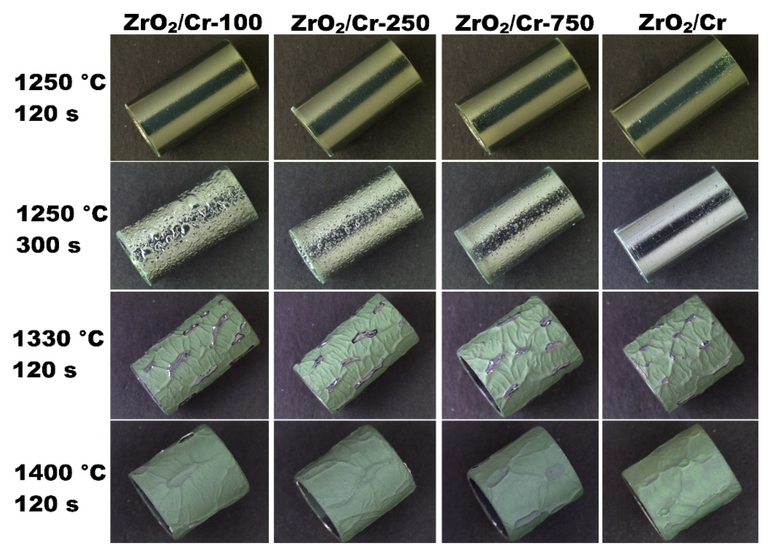
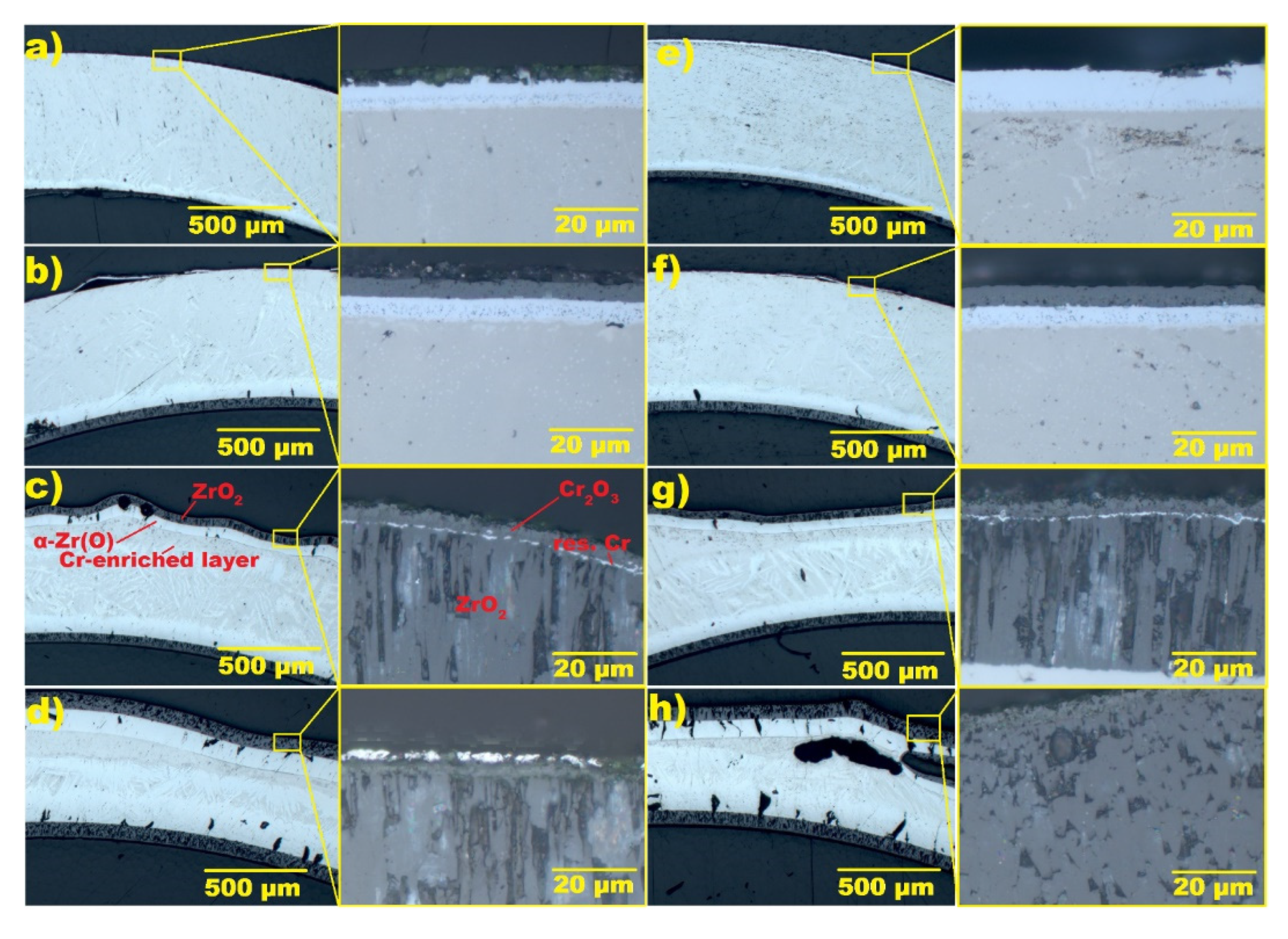
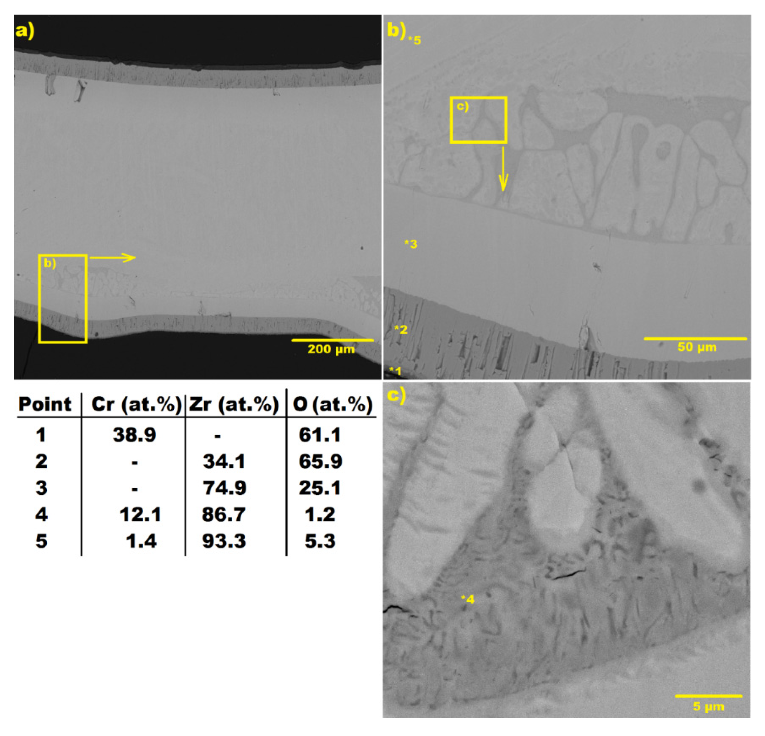
3.3. Steam Oxidation at 1200 °C

The E110 alloy samples with the ZrO2/Cr coatings were oxidized in a water steam at 1200 °C for 1000 and 2000 s. Then, their weight gains were obtained and compared with the uncoated and the Cr-coated E110 alloy samples from ref. [18] (Table 3).
All coatings could protect the alloy samples from the oxidation in a steam as the weight gains of the coated samples (1.9–4.0 mg/cm2) were lower by one order of magnitude compared with that of the uncoated one (19.3–27.5 mg/cm2). However, the weight gains of the ZrO2/Cr samples were dependent on the multilayer structure of the ZrO2/Cr barrier. When the thickness of the ZrO2/Cr multilayers decreased from 750 to 100 nm, the weight gain increased. This was well observed for the samples after steam oxidation for 2000 s (3.2 → 4.0 mg/cm2). To determine a cause of this difference, the cross-section microstructure of the samples was examined by optical microscopy and SEM with an EDS attachment (Figure 7 and Figure 8).
According to the EDS measurements, a Cr2O3 scale was formed on outer surface of the samples due to oxidation of chromium layer in a water steam. Underneath the Cr2O3 scale, the layer with a high concentration of Cr (residual Cr layer) was found. Between the Cr2O3 scale and the residual Cr layer, a high number of cavities were observed that could be formed due to the outward cationic diffusion of Cr from the residual Cr and back diffusion of the vacancies at the Cr2O3/Cr interface [1]. The same cavities were also found at the interface of the alloy, which are usually observed for the Cr-coated zirconium alloys between the interdiffusion layer (Cr–Zr region) and Zr alloys [1,25]. These cavities could be produced by the Kirkendall mechanism when the movement of the diffusion interface for materials has a different diffusion coefficient. It is should be noted that the quantity and size of the cavities at the E110 alloy interface became noticeably higher when the samples were oxidized in water steam for 2000 s (Figure 8). Another important point is that the formation of these cavities was more pronounced for the samples with lower thicknesses of the ZrO2/Cr multilayers (ZrO2/Cr-100 and ZrO2/Cr-250 coatings in Figure 7). Based on the SEM and EDS data, the layer with Cr, Zr, and O content was found at the interface between the residual Cr and the Zr alloy, where the multilayer ZrO2/Cr barrier was prior to the oxidation tests. However, oxygen concentration was lower (19–24 at.%), which correspond to oxygen content in the initial barrier composed of Cr and ZrO2 (~33 at.%). Taking into account more pronounced formation of the cavities for the samples with thinner ZrO2/Cr multilayers, these cavities could be produced due to the interdiffusion of Cr and Zr at the ZrO2/Cr interfaces. In view of using magnetron sputtering for deposition of the ZrO2/Cr multilayers, the boundaries cannot be sharp between them and materials are mixed at the multilayer boundaries. This could be due to the use of substrate biasing during coating deposition, which is needed to form a dense coating microstructure by increasing adatom mobility [26]. Such an effect was earlier demonstrated by transmission electron microscopy in the case of Cr deposition on Zircaloy-4 alloy in ref. [27], where nanometer-thick interfacial layers of Zr(Fe, Cr)2 Laves phases were observed at the coating/alloy interface even after the coating process. To confirm this, EDS maps of Cr, Zr, and O were obtained for the cross-sections of the samples after oxidation in water steam at 1200 °C for 1000 s (Figure 9). The traces of Zr at the interface of the multilayer barrier were good, indicating the outward diffusion of Zr to surface of the sample. Such Zr traces were more visible on the EDS maps for the sample with the thinnest ZrO2/Cr multilayers (with the highest number of ZrO2/Cr interfaces). This indicated that the interdiffusion of Cr and Zr could occur at the multilayer ZrO2/Cr interfaces, and the multilayer structure of the barrier composed of Cr and ZrO2 layers could accelerate this.
Beneath the coatings, the layer of oxygen-stabilized α–Zr(O) phase was detected. Based on the EDS data, the content of O underneath the coating was higher (11–16 at.%) for the ZrO2/Cr-100 sample in comparison with the ZrO2/Cr sample (5–8 at.%). This difference was well observed from the optical images of the cross-sections, where sizes of α–Zr(O) grains were higher for the samples with the thinnest ZrO2/Cr multilayers (Figure 7(a.1,a.2)). Due to forming the cavities at the Cr2O3 oxide/residual Cr and coating/alloy interfaces, these interfaces can become non-uniform and the voids are produced in the coatings that is additionally highlighted in Figure 7(a.2). Thereby, oxygen can penetrate through these voids to the alloy during steam oxidation and results in forming an α–Zr(O) phase underneath the coatings. Such a difference of the samples also indicated that a higher quantity of oxygen could penetrate through the coatings to the alloy when the thickness of the ZrO2/Cr multilayers was low. It also explains the increase of the weight gains of the samples with thinner ZrO2/Cr multilayers after steam oxidation (Table 3).

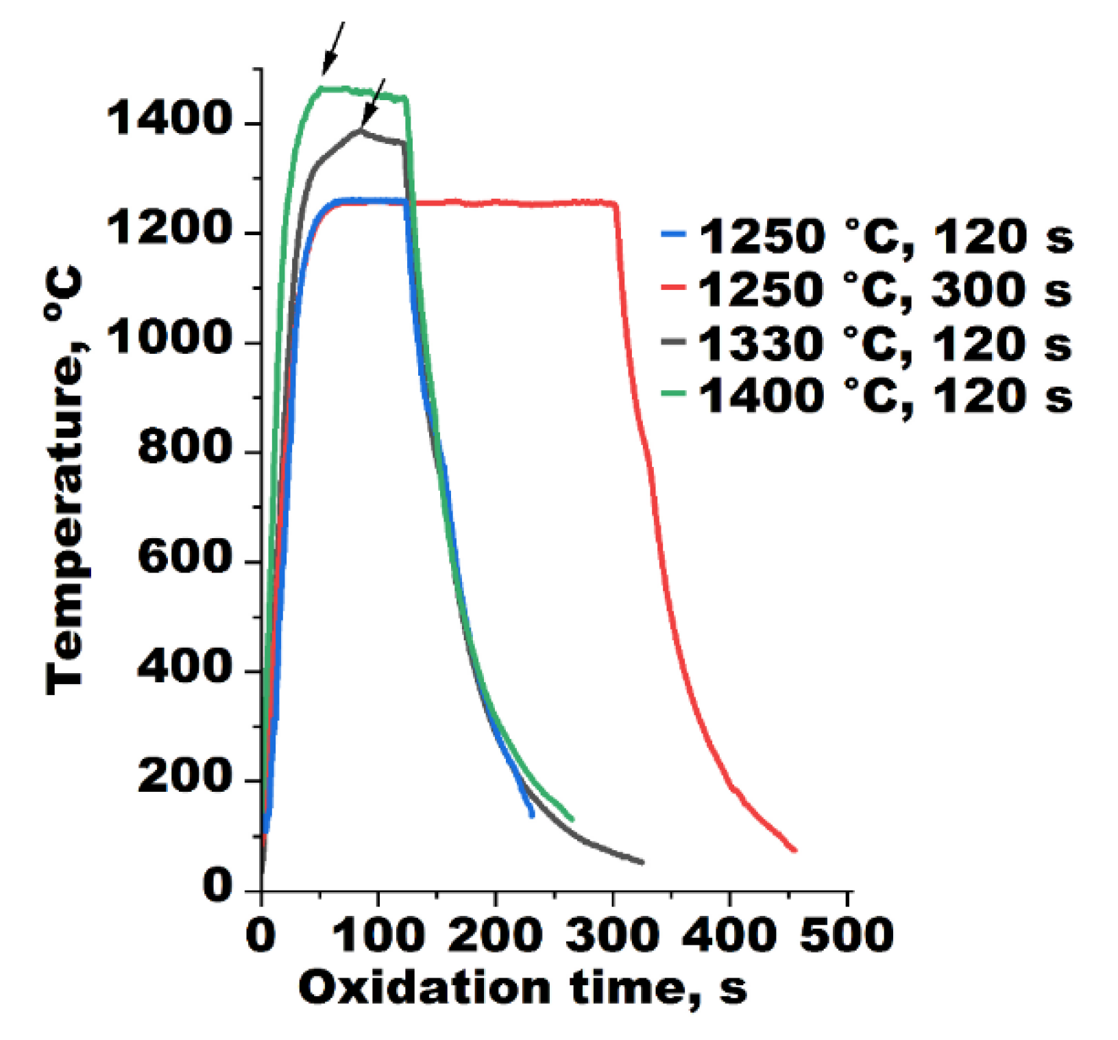
3.4. Steam Oxidation at 1250–1400 °C

The experimental ZrO2/Cr samples were oxidized in water steam at 1250, 1330, and 1400 °C for 120 and 300 s. Their appearances after the oxidation tests are shown in Figure 10.
The surfaces of the samples became green-colored after oxidation in water steam at 1250 °C for 120 s. This is typical behavior for Cr-coated Zr alloys after steam oxidation and indicates the formation of an outer Cr2O3 layer. No other visible changes of surface morphologies were observed after oxidation at 1250 °C for 120 s. However, a wavy profile of the samples was detected after 300 s oxidation at 1250 °C. As the coatings had a higher quantity of the ZrO2/Cr multilayers, the wavy profile became more pronounced. At higher temperatures (1330 and 1400 °C), the surface of the samples again changed. The samples had a morphology with continuous blisters that is similar to earlier observed in the oxidation tests of the Cr-coated samples at 1400 °C for 100 s [1,28]. It also seems that melting of the sample surface was identified for Cr-coated Zr alloys. Some regions of sample surface had a metallic color after the tests at 1330 °C. After oxidation at 1400 °C, the regions with a metallic color disappeared, and all areas of the surface became green-colored. Moreover, the sizes of blisters became higher, but their quantity decreased for steam oxidation tests at 1400 °C in comparison with the tests performed at 1330 °C. Such changes of the sample surface can indicate the formation of an eutectic Cr–Zr interlayer with the future melting of this layer growing blisters and causing their collapse. Due to this, the E110 alloy can lose its protection and interact with water steam. Indeed, the temperature profiles of the samples during steam oxidation had some ramps during the oxidation tests performed at 1330 and 1400 °C (Figure 11). As the coatings melted before the end of the tests (less than 120 s), some surface regions of the E110 alloy sample were directly exposed to water steam and rapidly oxidized. The oxidation reaction of Zr alloys is exothermic [29], so the samples can be overheated due to the oxidation of the non-protective area of zirconium on the outer and inner surfaces of Zr-cladding samples. The maximum temperature of the samples was equal to 1387 and 1465 °C at the tests performed at 1330 and 1400 °C. Such an effect was not found for the oxidation tests at 1250 °C for 120 and 300 s.
Figure 12 presents the optical images of the cross-section microstructure of the ZrO2/Cr-100 and ZrO2/Cr samples after steam oxidation at 1250, 1330, and 1400 °C.
The cross-section microstructure of both samples after oxidation in a water steam at 1250 °C was the same as it was after oxidation tests at 1200 °C (Figure 7). According to the optical images with high magnification, the Cr2O3 oxide layer was formed on the outer surface; below, a layer of residual Cr with a lot of cavities was found at the region of coating/alloy interface. Moreover, the sample with the thinnest ZrO2/Cr multilayers had a higher number of blisters than that of the sample with the single-layer ZrO2 barrier. The same effect was obtained in the steam oxidation tests performed at 1200 °C.
At a higher temperature of the steam oxidation tests (1330 and 1400 °C), the cross-section microstructure of the samples changed significantly. Based on the SEM and EDS data (Figure 13), the outer layer was composed of Cr (38.9 at.%) and O (61.1 at.%), which indicates the formation of a Cr2O3 scale on the sample surface. Underneath, the residual Cr layer was observed, which seems as to be a thin metallic line in the cross-section optical images on the example in Figure 12c. Below it, a layer with Zr (34.1 at.%) and O (65.9 at.%) content was found; this layer has a dark-gray color in the optical images. Then, the white layer with a low oxygen (25.1 at.%) content was observed, which corresponds to the α–Zr(O) phase according to the Zr–O phase diagram [30]. Underneath the oxide, the Cr-enriched zone was found (12.1 at.% in point #4). This consists of Cr-depleted prior β–Zr dendrites and Cr-enriched inter-dendritic zones that were also found for steam oxidation tests beyond 1300 °C [8] and in the high-temperature transient tests (up to 1600 °C) [31]. Such a zone has a typical microstructure and elemental composition, as is seen in Figure 13c and in the previous studies [1,8,31].
The EDS measurement in #5 points out that the layer has some Cr content (1.4 at.%), indicating the Cr diffusion to the E110 alloy. However, the Cr content in this region of the alloy was low enough to form an eutectic Cr–Zr layer. The comparison of thicknesses of the oxide and Cr-enriched layers of the samples did not show a strong difference in oxidation kinetics of the samples with different ZrO2/Cr barriers for temperatures above 1330 °C. However, it is evident that high number of the ZrO2/Cr interfaces can result in accelerating Cr–Zr interdiffusion, which was found for steam oxidation at 1200 and 1250 °C.
One additional experiment was also performed to analyze the zone of blister collapse on the sample surface. The SEM images of the ZrO2/Cr-100 sample after oxidation in water steam at 1400 °C for 120 s and the corresponding EDS maps of Cr, Zr, and O in the region of blister collapse are shown in Figure 14.
According to the EDS maps, strong signals of O (65.2 at.%) and Cr (31.6 at.%) point to the formation of a Cr2O3 scale on the outer surface. Extremely heterogeneous and uneven surface morphology was observed at the bottom of the crater, where the blister collapsed (Figure 14b). It seems as if a boiling surface, which was quickly solidificated due to oxidation in water steam, when the blister collapsed. Indeed, the eutectic Cr–Zr interlayer and a lot of cavities at the coating/alloy interface were formed due to the Cr–Zr interdiffusion. The melting point of the eutectic Cr–Zr interlayer was equal to 1332 °C [7,8], which resulted in melting the sample underneath the coating in the oxidation tests performed at 1330 and 1400 °C. Figure 14b shows some cracks in the surface “spikes” that are most likely formed due to outward release of Kirkendall cavities from the melted Cr–Zr region. The outer surface layer can move and liquid Cr–Zr region can be opened to a direct interaction with water steam due to the capillary effect of the liquid Cr–Zr interlayer and local swelling induced by a volume change. So, as the liquid Cr–Zr region was composed of Cr2Zr and Zr phases, it oxidized with the formation of Cr and ZrO2 phases because of the high chemical affinity of Zr to O [32]. This is good, as confirmed by the elemental composition of the surface and typical microstructure in the image at the high magnification in the Figure 14c. So, the surface can be quickly solidificated as the ZrO2 phase has a higher melting point (2709 °C) than the surface temperature during the steam oxidation tests.

3.5. Analysis of the Oxidation Process

A schematic diagram of the oxidation process for the Cr-coated E110 alloy with ZrO2/Cr multilayers is presented in Figure 15. At the first stage of oxidation, an outer Cr layer was oxidized in water steam with a growing Cr2O3 scale, while underneath, the residual Cr layer remained (Figure 15b). Back diffusion of the vacancies at the Cr2O3/Cr interface and the outward cationic diffusion of Cr from the residual Cr layer/Cr interface caused the formation of cavities at the Cr2O3/Cr interface, as was shown in ref. [1]. The cavities were also generated at the ZrO2/Cr multilayer interfaces due to mutual diffusion of Cr and Zr by the Kirkendall mechanism. This could be due to the presence of mixed regions and non-smooth nanoscale boundaries of the ZrO2/Cr multilayers obtained by magnetron sputtering with the application of bias on the heated substrate (Table 1). The next description of oxidation behavior should be divided into two possible scenarios depending on the temperature of the Cr-coated E110 alloy samples.
Firstly, we discuss the temperature region of 1200–1250 °C. At the second stage of oxidation (Figure 15c), the cavities at the Cr2O3/Cr and ZrO2/Cr multilayer could be combined in volume voids (blisters) as well observed in the cross-section images of the samples after the oxidation tests (Figure 7 and Figure 8). The volume change of the coatings under blistering could lead to an accelerated inward diffusion of oxygen to the Zr alloy and the outward diffusion of zirconium to the Cr multilayers. The latter led to a stabilization of α–Zr(O) phase in the prior β–Zr alloy underneath the coating (Figure 15d). It is most likely that the abovementioned processes will be continued up to the failure of the coating/alloy interface due to blister collapse and open a free pathway to the zirconium alloy for water steam. As shown in Figure 12 (the images of the samples after oxidation at 1250 °C for 300 s), the oxidation behavior of the Cr-coated Zr alloy with the barrier from the ZrO2/Cr multilayers is strongly dependent on the number of the multilayers and their thicknesses.
Steam oxidation of the Cr-coated E110 alloy samples with the ZrO2/Cr multilayers has another scenario at 1330–1400 °C. At the second stage of oxidation (Figure 15e), the Cr–Zr interlayers at the ZrO2/Cr multilayer interfaces could be melted when the temperature of the E110 alloy samples reached the melting point of the eutectic Cr–Zr phase (~1332 °C [7,8]). The liquid Cr–Zr regions caused a capillary effect, which resulted in displacing the coating on the alloy surface. Both the capillary effect and volume change due to blistering led to accelerating inward oxygen diffusion. When oxygen interacts with liquid Cr–Zr interlayers, the ZrO2 and metallic Cr will be formed due to the redox reaction [33,34]. Chromium will diffuse into the Zr alloy, leading to the formation of a solid-state Cr-enriched zone in the prior β–Zr alloy underneath the coating. Due to the capillary effect, the E110 alloy can lose the protection of the coating in some regions and the blisters can go out to the surface with opening pathways to the Zr alloy for steam from the outer atmosphere (Figure 15f), as is clearly seen in Figure 10. Thus, the oxidation of the inner walls of the newly formed pathways leads to the formation of inner ZrO2 on the walls of these pathways that can be beneath non-oxidized regions of the Zr alloy. Such a structure is clearly observed in the cross-section microstructure image in Figure 12h. The Zr alloy oxidation in the inner regions is explained by the higher melting temperature of ZrO2 in comparison with the cladding temperature in the tests. Inward oxygen diffusion through the remained coating leads to the stabilization of α–Zr(O) phase underneath the coating and the shift of Cr-enriched Zr zone in deeper regions of the Zr alloy due to higher diffusion rate and solubility of Cr in β–Zr alloy than that of in α–Zr phase. This process of the accelerated Cr diffusion caused by α-phase stabilizers of Zr alloy (O or N) is shown and discussed in several studies, e.g., in refs. [18,31].
The obtained results point out that the multilayers composed from Zr and Cr and/or their oxides obtained by magnetron sputtering can work as inner sources for Cr–Zr interdiffusion. This leads to a decrease in the corrosion resistance of the coated Zr alloys at temperatures near the melting point of the eutectic Cr–Zr phase and/or at higher temperatures.

4. Conclusions

Chromium coatings with a barrier composed of ZrO2/Cr multilayers were obtained onto E110 alloy samples. Then, the Cr-coated E110 alloy samples were tested under the conditions of thermal cycling in air atmosphere at 1000 °C and in steam at 1200–1400 °C. Afterwards, oxidation behavior of the Cr-coated samples was studied depending on the coating type. The decrease of the thickness of the ZrO2/Cr multilayers from 750 to 100 nm resulted in the increase of cracking resistance of the coatings. Coating spallation became more pronounced for the coatings with higher quantities of the ZrO2/Cr multilayer interfaces. The oxidation of coated E110 alloy samples during thermal cycling was mainly affected by coating spallation as higher weight gain values (1 mg/dm2) belonged to the samples with higher amount of coating spallation (5.0 mm−1) after 50 thermal cycles. Interfaces of the ZrO2/Cr multilayers could act as a source of cavities that are formed by Kirkendall mechanism during high-temperature steam oxidation (1200–1400 °C). The larger size of the cavities and their quantity were observed for the samples with thinner ZrO2/Cr multilayers (100 and 250 nm) in comparison with the sample coated by the single-layer ZrO2 barrier. This indicates that the multilayer barrier composed of Cr and ZrO2 layers led to an accelerating interdiffusion of Cr and Zr for Cr-coated E110 alloy samples at high temperatures in steam.

Author Contributions

Conceptualization, D.V.S.; methodology, D.V.S.; validation, D.V.S., A.G.M. and I.A.S.; formal analysis, D.V.S.; investigation, D.V.S., S.E.R., I.A.S., K.K.P. and K.V.S.; resources, A.G.M. and A.A.M.; data curation, S.E.R. and N.S.S.; writing—original draft preparation, D.V.S.; writing—review and editing, A.G.M.; visualization, S.E.R.; supervision, D.V.S.; project administration, D.V.S.; funding acquisition, D.V.S. All authors have read and agreed to the published version of the manuscript.

Funding

The reported study was funded by RFBR and ROSATOM, project No. 20-21-00037.

Institutional Review Board Statement

Not applicable.

Informed Consent Statement

Not applicable.

Data Availability Statement

Not applicable.

Acknowledgments

This research was supported by TPU development program. The authors thank Maxim Rudmin for SEM and EDS measurements.

Conflicts of Interest

The authors declare no conflict of interest.

References

  1. Brachet, J.C.; Rouesne, E.; Ribis, J.T.; Guilbert, S.; Urvoy, G. High temperature steam oxidation of chromium-coated zirconium-based alloys: Kinetics and process. Corros. Sci. 2020, 167, 108537. [Google Scholar] [CrossRef]
  2. Chen, H.; Wang, X.; Zhang, R. Application and development progress of Cr-based surface coatings in nuclear fuel element: I. selection, preparation, and characteristics of coating materials. Coatings 2020, 10, 808. [Google Scholar] [CrossRef]
  3. Chen, H.; Wang, X.; Zhang, R. Application and development progress of Cr-based surface coating in nuclear fuel elements: II. Current status and shortcomings of performance studies. Coatings 2020, 10, 835. [Google Scholar] [CrossRef]
  4. Sidelev, D.V.; Kashkarov, E.B.; Syrtanov, M.S.; Krivobokov, V.P. Nickel-chromium (Ni–Cr) coatings deposited by magnetron sputtering for accident tolerant nuclear fuel claddings. Surf. Coat. Technol. 2019, 369, 69–78. [Google Scholar] [CrossRef]
  5. Kashkarov, E.; Afornu, B.; Sidelev, D.; Krinitcyn, M.; Gouws, V.; Lider, A. Recent advances in protective coatings for accident tolerant Zr-based fuel claddings. Coatings 2021, 11, 557. [Google Scholar] [CrossRef]
  6. Brachet, J.; Idarraga-Trujillo, I.; Le-Flem, M.; Le-Saux, M.; Vandenberghe, V.; Urvoy, S.; Rouesne, E.; Guilbert, T.; Toffolon-Masclet, C.; Tupin, M.; et al. Early studies on Cr-coated Zircaloy-4 as enhanced accident tolerant nuclear fuel claddings for light water reactors. J. Nucl. Mater. 2019, 517, 268–285. [Google Scholar] [CrossRef]
  7. Zeng, K.; Hamalainen, M.; Luoma, R. A thermodynamic assessment of the Cr–Zr system. Int. J. Mater. Res. 1993, 94, 23–28. [Google Scholar] [CrossRef]
  8. Yang, J.; Stegmaier, U.; Tang, C.; Steinbrück, M.; Grobe, M.; Wang, S.; Seifert, H.J. High temperature Cr-Zr interaction of two types of Cr-coated Zr alloys in inert gas environment. J. Nucl. Mater. 2021, 547, 152806. [Google Scholar] [CrossRef]
  9. Michau, A.; Ougier, M.; Maskrot, H.; Brachet, J.-C.; Guilbert, T.; Palancher, H.; Bischoff, J.; Pouillier, E. Interlayers for Cr-coated nuclear fuel claddings: Preliminary study of Mo. In Proceedings of the NuMat 2020, Ghent, Belgium, 26 October 2018; Volume 1. [Google Scholar] [CrossRef]
  10. Syrtanov, M.S.; Kashkarov, E.B.; Abdulmenova, A.V.; Sidelev, D.V. High-temperature oxidation of Zr-1Nb zirconium alloy with protective Cr/Mo coating. Surf. Coat. Technol. 2020, 439, 128459. [Google Scholar] [CrossRef]
  11. Kalin, B.A.; Yashin, A.S.; Dzhumaev, P.S.; Safonov, D.A.; Korenevsky, E.L.; Fedorov, D.A.; Novikov, V.V.; Kuznetsov, V.I.; Fedotov, P.V.; Krivobokov, V.P.; et al. Features of creating wear-resistant anti-corrosion coatings with a barrier layer on fragments of fuel claddings from E110 o.ch. IOP Conf. Series Mater. Sci. Eng. 2020, 1005, 012009. [Google Scholar] [CrossRef]
  12. Wang, X.; Guan, H.; Liao, Y.; Zhu, M.; Xu, C.; Jin, X.; Liao, B.; Xue, W.; Zhang, Y.; Bai, G.; et al. Enhancement of high temperature steam oxidation resistance of Zr–1Nb alloy with ZrO2/Cr bilayer coating. Corros. Sci. 2021, 187, 109494. [Google Scholar] [CrossRef]
  13. Wang, Y.; Tang, H.; Han, X.; Fenga, W.; Zhou, X.; Peng, S.; Zhang, H. Oxidation resistance improvement of Zr-4 alloy in 1000 °C steam environment using ZrO2/FeCrAl bilayer coating. Surf. Coat. Technol. 2018, 349, 807–815. [Google Scholar] [CrossRef]
  14. Krejci, J.; Kabatova, J.; Manoch, F.; Koci, J.; Cvrcek, L.; Malek, J.; Krum, S.; Sutta, P.; Bublikova, P.; Halodova, P. Development and testing of multicomponent fuel cladding with enhanced accidental performance. Nucl. Eng. Technol. 2020, 597, 597–609. [Google Scholar] [CrossRef]
  15. Pan, X.; Qiu, L.; Hu, X.; Jiang, H. Corrosion and wear properties of Cr coating and ZrO2/Cr bilayer coating on Zr-4 alloy. Coatings 2022, 12, 1281. [Google Scholar] [CrossRef]
  16. Liu, J.; Hao, Z.; Cui, Z.; Ma, D.; Lu, J.; Cui, Y.; Li, C.; Liu, W.; Xie, S.; Huang, P.; et al. Investigation of the oxidation mechanisms of superlattice Cr-CrN/TiSiN-Cr multilayer coatings on Zircaloy substrates under high-temperature steam atmospheres. Corros. Sci. 2021, 192, 109782. [Google Scholar] [CrossRef]
  17. Xiao, W.; Chen, H.; Liu, X.; Tang, D.; Deng, H.; Zou, S.; Ren, Y.; Zhou, X.; Lei, M. Thermal shock resistance of TiN-, Cr-, and TiN/Cr-coated zirconium alloy. J. Nucl. Mater. 2019, 526, 151777. [Google Scholar] [CrossRef]
  18. Sidelev, D.V.; Ruchkin, S.E.; Syrtanov, M.S.; Kashkarov, E.B.; Shelepov, I.A.; Malgin, A.G.; Polunin, K.K.; Stoykov, K.V.; Mokrushin, A.A. Protective Cr coatings with CrN/Cr multilayers for zirconium fuel claddings. Surf. Coat. Technol. 2022, 433, 128131. [Google Scholar] [CrossRef]
  19. Sidelev, D.V.; Syrtanov, M.S.; Ruchkin, S.E.; Pirozhkov, A.V.; Kashkarov, E.B. Protection of Zr alloy under high-temperature air oxidation: A multilayer coating approach. Coatings 2021, 11, 227. [Google Scholar] [CrossRef]
  20. Syrtanov, M.; Pirozhkov, A.; Sidelev, D. In-situ phase transformations in CrN/Cr-coated E110 alloy under high temperature. Eng. Mater. 2022, 910, 940–946. [Google Scholar] [CrossRef]
  21. Li, Z.; Liu, C.; Chen, Q.; Yang, J.; Liu, J.; Yang, H.; Zhang, W.; Zhang, R.; He, L.; Long, J.; et al. Microstructure, high-temperature corrosion and steam oxidation properties of Cr/CrN multilayer coatings prepared by magnetron sputtering. Corros. Sci. 2021, 191, 109755. [Google Scholar] [CrossRef]
  22. Xiang, Y.; Liu, C.; Li, Z.; Liu, H.; Yang, J.; Yang, H.; Zhang, R.; He, L.; Liu, J.; Long, J.; et al. Interface stability and microstructural evolution of the (Cr/CrN)24-coated zirconium alloy under different thermal shock temperatures. Surf. Coat. Technol. 2022, 429, 127947. [Google Scholar] [CrossRef]
  23. Procedure for Conducting Oxidation and Post-Quench Ductility Tests with Zirconium-Based Cladding Alloys; Argonne National Laboratory: Lemont, IL, USA, 2009. Available online: http://pbadupws.nrc.gov/docs/ML0909/ML090900841.pdf (accessed on 1 April 2021).
  24. Polunin, K.K.; Mokrushin, A.A.; Urusov, A.A. Study of high temperature oxidation of zirconium fuel element claddings with chromiferous coatings. Mater. Sci. Eng. 2020, 1005, 012002. [Google Scholar] [CrossRef]
  25. Gong, W.; Zhang, H.; Wu, C.; Tian, H.; Wang, X. The role of alloying elements in the initiation of nanoscale porosity in oxide films formed on zirconium alloys. Corros. Sci. 2013, 77, 391–396. [Google Scholar] [CrossRef]
  26. Pawlewicz, W.T.; Hays, D.D. Microstructure control for sputter-deposited ZrO2, ZrO2•CaO and ZrO2•Y2O3. Thin Solid Film. 1982, 94, 31–45. [Google Scholar] [CrossRef]
  27. Ribis, J.; Wu, A.; Brachet, J.-C.; Barceló, F.; Arnal, B. Atomic-scale interface structure of a Cr-coated Zircaloy-4 material. J. Mater. Sci. 2018, 53, 9879–9895. [Google Scholar] [CrossRef]
  28. Brachet, J.C.; Guilbert, T.; Saux, M.L.; Rousselot, J.; Nony, G.; Toffolon-Masclet, C.; Michau, A.; Schuster, F.; Palancher, H.; Bischoff, J.; et al. Behavior of Cr-coated M5 claddings during and after high temperature steam oxidation from 800 °C up to 1500 °C (LOss-of-coolant accident & design extension conditions). In Proceedings of the WRFPM/TOPFUEL, Prague, Czech Republic, 30 September 2018; Volume 30. [Google Scholar]
  29. Duan, Z.; Yang, H.; Satoh, Y.; Murakami, K.; Kano, S.; Zhao, Z.; Shen, J.; Abe, H. Current status of materials development of nuclear fuel cladding tubes for light water reactors. Nucl. Eng. Des. 2017, 316, 131–150. [Google Scholar] [CrossRef]
  30. Abriata, J.P.; Garces, J.; Versaci, R. The O–Zr (oxygen-zirconium) system. Bull. Alloy Phase Diagr. 1986, 7, 116–124. [Google Scholar] [CrossRef]
  31. Liu, J.; Tang, C.; Steinbrück, M.; Yang, J.; Stegmaier, U.; Große, M.; Yun, D.; Seifert, H.J. Transient experiments on oxidation and degradation of Cr-coated Zircaloy in steam up to 1600 °C. Corros. Sci. 2021, 192, 109805. [Google Scholar] [CrossRef]
  32. Barin, I. Thermochemical Data of Pure Substances; VCH: Weinheim, Germany, 1989. [Google Scholar]
  33. Han, X.; Xue, J.; Peng, S.; Zhang, H. An interesting oxidation phenomenon of Cr coatings on Zry-4 substrates in high temperature steam environment. Corros. Sci. 2019, 156, 117–124. [Google Scholar] [CrossRef]
  34. Liu, J.; Steinbrück, M.; Große, M.; Stegmaier, U.; Tang, C.; Yun, D.; Yang, Y.; Cui, Y.; Seifert, H.S. Systematic investigations on the coating degradation mechanism during the steam oxidation of Cr-coated Zry-4 at 1200 °C. Corros. Sci. 2022, 202, 110310. [Google Scholar] [CrossRef]
Figure 1. Optical images of the cross-section microstructure of the E110 alloy samples with (a) ZrO2/Cr-100, (b) ZrO2/Cr-250, (c) ZrO2/Cr-750, and (d) ZrO2/Cr coatings. Cross-section SEM image of a barrier layer of the ZrO2/Cr-100 sample is added.
Coatings 12 01409 g001
Figure 2. The elemental (Cr, Zr, and O) depth distributions in the (a) ZrO2/Cr-100, (b) ZrO2/Cr-250, (c) ZrO2/Cr-750, and (d) ZrO2/Cr coatings obtained onto the E110 alloy plates.
Coatings 12 01409 g002
Figure 3. The dependence of the weight gain of the samples on a cycle number.
Coatings 12 01409 g003
Figure 4. Optical images of the cross-section microstructure of the E110 alloy samples with (a,a1) ZrO2/Cr-100, (b,b1) ZrO2/Cr-250, (c,c1) ZrO2/Cr-750 and (d,d1) ZrO2/Cr coatings after the short-term thermal cycling. The arrows indicate spallation of the coatings.
Coatings 12 01409 g004
Figure 5. Optical images of the cross-section of the ZrO2/Cr-100 sample after 50 thermal cycles at different magnification: (a)—×50; (b)—×200.
Coatings 12 01409 g005
Figure 6. Cross-section SEM image of the ZrO2/Cr-750 sample after 50 cycles and corresponding EDS maps of Cr, Zr, O, and N.
Coatings 12 01409 g006
Figure 7. Optical images of the cross-section microstructure of ZrO2/Cr-100 (a.1,a.2), ZrO2/Cr-250 (b.1,b.2), ZrO2/Cr-750 (c.1,c.2), and ZrO2/Cr (d.1,d.2) samples after oxidation in steam at 1200 °C for 1000 and 2000 s, respectively.
Coatings 12 01409 g007
Figure 8. Cross-section SEM microstructure of the ZrO2/Cr-100 (a,b) and ZrO2/Cr (c,d) samples after steam oxidation at 1200 °C for 1000 and 2000 s, respectively.
Coatings 12 01409 g008
Figure 9. Cross-section SEM image of the ZrO2/Cr-100 sample after oxidation in water steam at 1200 °C for 1000 s and the corresponding EDS maps of Cr, Zr, and O.
Coatings 12 01409 g009
Figure 10. Appearance of the samples after steam oxidation at 1250, 1330, and 1400 °C for 120 and 300 s.
Coatings 12 01409 g010
Figure 11. Temperature profiles of the samples during oxidation in water steam at 1250, 1330, and 1400 °C.
Coatings 12 01409 g011
Figure 12. Optical images of the cross-section microstructure of the ZrO2/Cr-100 (ad) and ZrO2/Cr (eh) samples after steam oxidation at 1250 °C (120 and 300 s), 1330 °C (120 s), and 1400 °C (120 s), respectively.
Coatings 12 01409 g012
Figure 13. Cross-section SEM microstructure of the ZrO2/Cr-100 sample after oxidation in water steam at 1400 °C for 120 s obtained at different magnification: (a)—×300; (b)—×1500; (c)—×10,000. Points (*) indicate the positions of EDS measurements.
Coatings 12 01409 g013
Figure 14. SEM images of the ZrO2/Cr-100 sample after oxidation in water steam at 1400 °C for 120 s and the corresponding EDS maps of Cr, Zr, and O of the sample at different magnification: (a)—×100; (b)—×2000; (c)—×8000. Points (*) indicate the positions of EDS measurements.
Coatings 12 01409 g014
Figure 15. Schematic diagram of the oxidation process for the Cr-coated Zr alloy with the ZrO2/Cr multilayers: (a)—initial state; (b)—stage I; (c,d)—stage II for 1200–1250 °C; (e,f)—stage II for 1330–1400 °C.
Coatings 12 01409 g015
Table 1. The deposition conditions of the ZrO2/Cr coatings.
SampleBarrier Layerh(Cr), µmUb, Vjs, mA/cm2t, hTs, °C
Nh, nm
ZrO2/Cr115008.5 ± 0.2−50726.9346
ZrO2/Cr-100301006.9 ± 0.2726.6343
ZrO2/Cr-250122507.0 ± 0.1716.7348
ZrO2/Cr-75047506.9 ± 0.1736.8345
Note:N—number of ZrO2 and Cr multilayers; h—thickness of individual multilayer; h(Cr)—thickness of outer Cr layer; Ub—substrate bias potential; js—averaged ion current density on the substrate; t—total deposition time; Ts—maximal temperature of the substrate.
Table 2. The Lc and Ls parameters of the coatings.
SampleCr [18]ZrO2/CrZrO2/Cr-100ZrO2/Cr-250ZrO2/Cr-750
Lc, mm−14.62.02.19.315.1
Ls, mm−1-1.25.03.52.2
Table 3. The weight gains of the samples after oxidation in a steam at 1200 °C for 1000 and 2000 s.
SampleWeight Gain, mg/cm2
1000 s2000 s
ZrO2/Cr-1002.24.0
ZrO2/Cr-2501.93.7
ZrO2/Cr-7501.93.2
ZrO2/Cr1.92.6
Cr [18]2.02.9
Uncoated E110 alloy [18]19.327.5
Publisher’s Note: MDPI stays neutral with regard to jurisdictional claims in published maps and institutional affiliations.

