1. Introduction
The plasma process has been widely used in many semiconductor processes because it has several advantages over wet processes. Generally, a plasma process generates various plasma species (radicals and ions) that respond to a material surface. The energy and mass distributions of the ions and radicals in a plasma depend on various process parameters, and they play an important role in controlling semiconductor processes such as etching, cleaning, and deposition. Thus, it is important to measure and analyze the distribution of the plasma species in a plasma [
1,
2,
3,
4,
5,
6,
7].
The radio frequency (RF) bias frequency applied to substrates affects the ion energy distribution of ionic species. It shows the ion energy distribution according to ion behavior across the sheath on the substrate. The RF bias power applied to substrates also affects ion energy distribution according to the change in sheath voltage. Furthermore, the RF bias power applied to substrates generates a self-bias voltage and affects the energy of ions entering the substrate. Recently, the high aspect ratio contact (HARC) etching process has increasingly gained importance as an etching process [
8,
9,
10]. The high ionic energy required in the HARC etching process is generated according to the RF bias power. Therefore, IED measurements according to RF bias power are very important.
The measurement of radical species and density plays an important role in understanding the etching or deposition process using plasma. Radical density and production ratios generated as a result of processes such as ionization and dissociation affect the chemical reaction with the substrate, which changes the process results. In addition, the measurement of radical species and density is applied to theoretical calculations to improve the accuracy of process calculation results. Moreover, energy and mass distribution measurements of ions and radicals are required for new gases, such as eco-friendly process gases [
11,
12,
13]. To this end, we aim to contribute to the data generation for new gases using a diagnostic device.
In this study, we used a commercial mass/energy analyzer to measure the ions and radicals in Ar, C4F8/Ar, and C4F6/Ar plasmas.
2. Materials and Methods
A plasma chamber was operated in the reactive ion etching (RIE) mode with a capacitively coupled plasma (CCP) source.
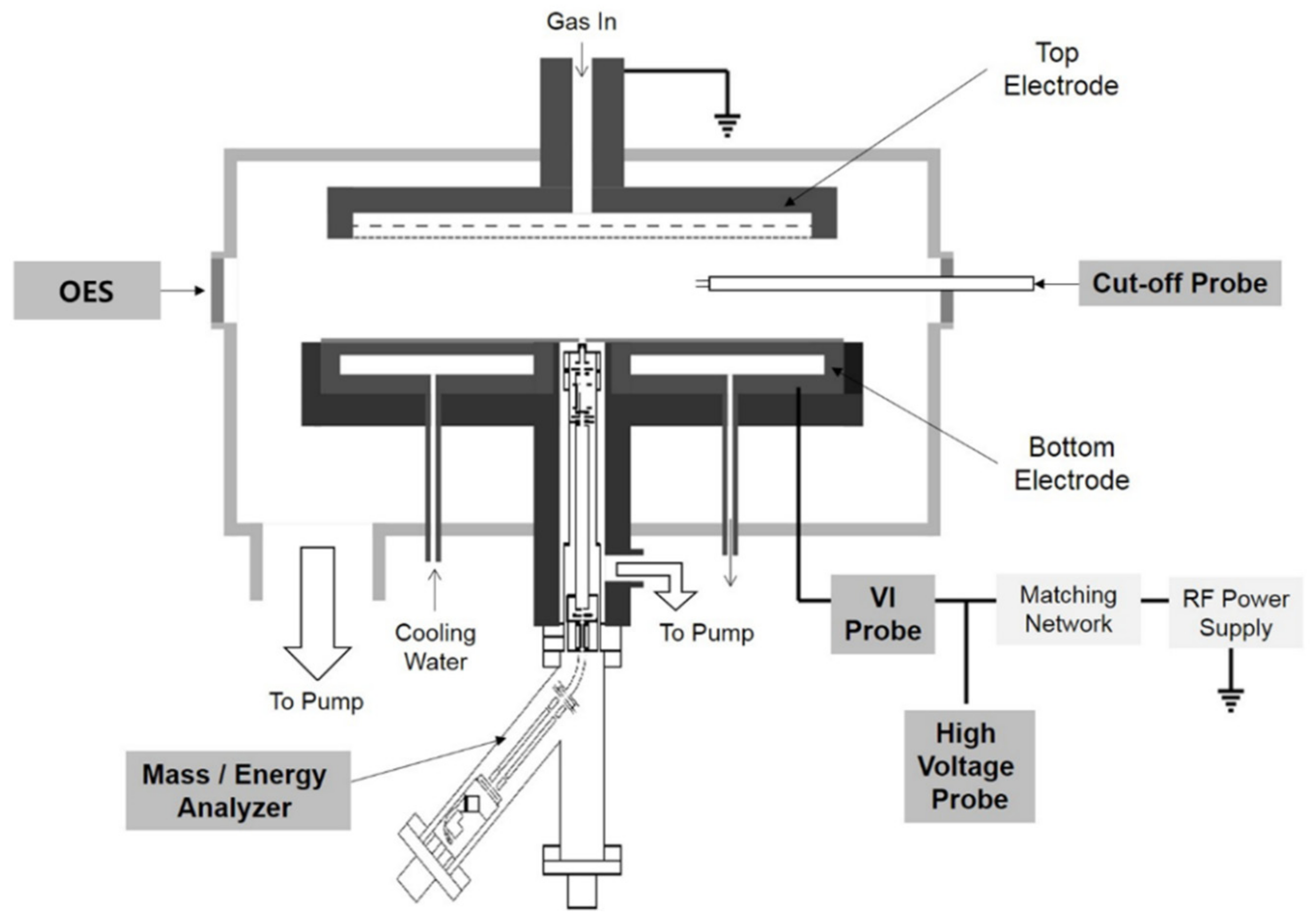
Figure 1 shows a schematic of the chamber with diagnostic tools. The electrode device used consists of two circular electrodes with a diameter of 300 mm and a spacing of 40 mm in the plasma chamber. The upper electrode was grounded. The bottom electrode was electrically insulated from the ground and connected to an RF power supply. Plasma was generated using a 13.56 MHz RF power supply (APF-3013, ASE, Yongin, Korea). The plasma chamber was vacuumed using a turbo molecular pump (STP-A1303C, Edwards, Chiba, Japan) and the base pressure was 2 × 10
−6 Torr. The etching process gas was uniformly injected through the showerhead located at the upper electrode. The gases used for the etching process were C
4F
8 and C
4F
6 at a ratio of 1:2 with Ar gas. The chamber pressure was adjusted to 10–30 mTorr using a mass flow controller (1179 Mass-Flo, MKS, Andover, MA, USA). Various diagnostic tools were installed in the plasma chamber to diagnose the plasma parameters. The diagnostic tools include a mass/energy analyzer, an optical emission spectroscopy (USB4000, Ocean Optics, Orlando, FL, USA), a cut-off probe, a VI probe (Octiv Suite, Impedans, Dublin, Ireland), and a high-voltage probe (P6015A, Tektronix, Oregon, OR, USA). The mass/energy analyzer (EQP1000, Hiden, Warrington, UK) was placed at the center of the powered electrode of the plasma source. A 100-μm aperture plate was installed 1 mm below the bottom electrode to measure the mass and energy distributions of the ions and radicals incident on the electrode.
The EQP1000 system comprises an ionization source region for measuring the neutral and radical ions, an electrostatic ion energy analyzer region for measuring the ion energy, and a quadrupole mass spectrometer region for mass measurement. The detector comprises a secondary electron multiplier region. The EQP1000 system has a mass range of up to 1000 amu and an energy range that can measure +/−1000 eV. The EQP1000 system maintains a base pressure of 1 × 10⁻⁸ Torr through differential pumping to satisfy the collision-free environment between the incident ions and the surrounding particles. We also used a reference voltage scanning method with an energy ranging from −1000 to +1000 V for a wide range of ion energy measurements. We obtained the energy and mass distributions of the ions and radicals using an inert gas (Ar) and processing gases (C4F8 and C4F6) and compared them with the results of other diagnostic equipment (cut off probe, VI probe) installed within the plasma source. An OES was used to measure the specific species in the plasma by measuring the specific emission lines from the plasma-emitting light and to observe the changes in the plasma density. The light emitted from the plasma was collected using a quartz optical fiber. The OES has a wavelength detection range of 200–1100 nm and a resolution of approximately 1 nm. An optical fiber was installed in front of the window installed at the vacuum port. A cutoff probe (COP) was used to measure the electron density of the plasma. A Langmuir probe is generally used to measure the electron density in a plasma. However, when reactive gases, such as fluorocarbon gases (CxFy), are used, the probe tip is etched or deposited. This distorts the signal and yields inaccurate measurement values. On the other hand, because the cutoff probe only requires a probe serving as an antenna capable of transmitting and receiving microwaves, it has the advantage of minimizing the influence of probe contamination. The cutoff probe was installed in the plasma chamber to measure the plasma density. The VI probe measures the parameters of the plasma power delivery. These parameters include the real power, forward power, reflected power, impedance, voltage, current, phase angle, harmonics, and ion flux. The VI probe was installed between the RF-powered electrode and the matching system to measure the voltage, current, and power applied to the electrode. The RF current was determined using a magnetic field measured through a pickup coil near the RF power line, and the RF voltage was measured in a noncontact manner through the electric field measured at the electrode. A high-voltage probe was installed between the RF-powered electrode and the matching network to measure the self-bias voltage. Because the self-bias voltage provides important information regarding the sheath potential that controls the energy of the ions incident on the substrate, it should be compared with the ion energy distribution of the ions through an ion energy analyzer. Plasma diagnostics using process gases was performed using a constructed plasma source and diagnostic tools. We obtained the energy and mass distributions of the ions and radicals using an inert gas (Ar) and processing gas (CxFy) and compared them with the results of other diagnostic tools installed within the plasma source.
3. Results and Discussion
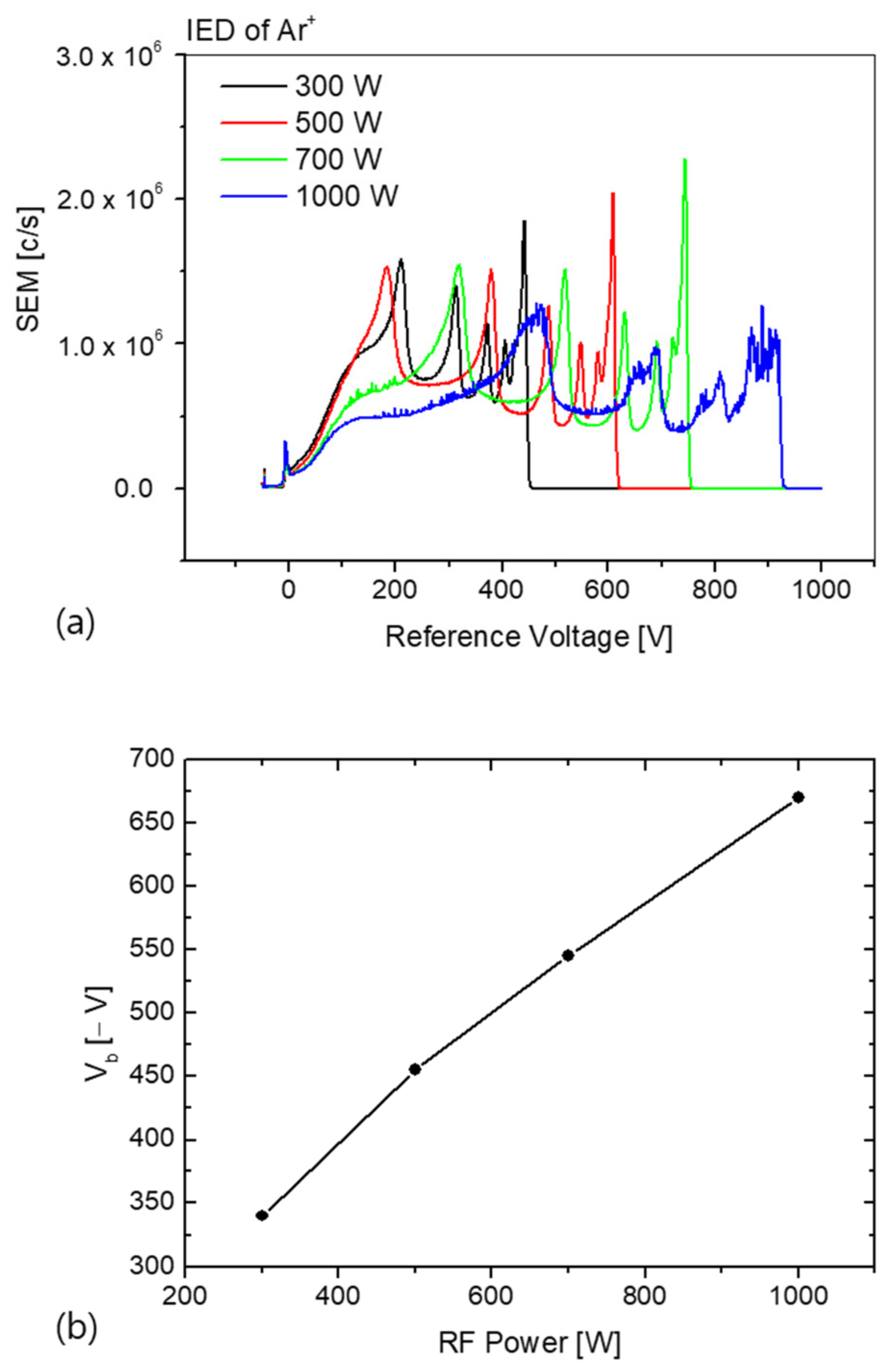
Figure 2a shows the variation in the ion energy distribution of the Ar
+ ion incident on the RF-powered electrode as a function of the applied RF power. The flow rate of the Ar gas was 180 sccm and the chamber pressure was maintained at 20 mTorr. As shown in the figure, the Ar
+ ion energy distribution has multiple peaks, attributed to the exchange of charges due to collisions with the Ar
+ ions through the RF-modulated sheath on the applied RF-powered electrode [
1,
14,
15]. The energy of the Ar
+ ions entering the electrode is the sum of the plasma potential and the self-bias potential formed on the RF-powered electrode.
In
Figure 2b,
Vb is the self-bias voltage measured using the high-voltage probe. Typically, the voltage across the electrode and ion transit is measured through a sheath potential of the form
. The self-bias voltage is the DC voltage component (
), excluding the RF cycle voltage (
. The RF power increased with an increase in the self-bias voltage. Increasing the self-bias voltage increases the energy of the Ar ions entering the RF-powered electrode. As a result, the Ar ion energy distribution widens with increasing RF power, as seen from Equation (1) [
16,
17,
18].
In a CxFy plasma, individual ionized CxFy
+ ion species are generated. The density and energy distributions of CxFy
+ ions vary depending on the plasma operation parameters, and CxFy radicals are generated by ionization, dissociation, and electron attachment. As an example of a CxFy
+ ion,
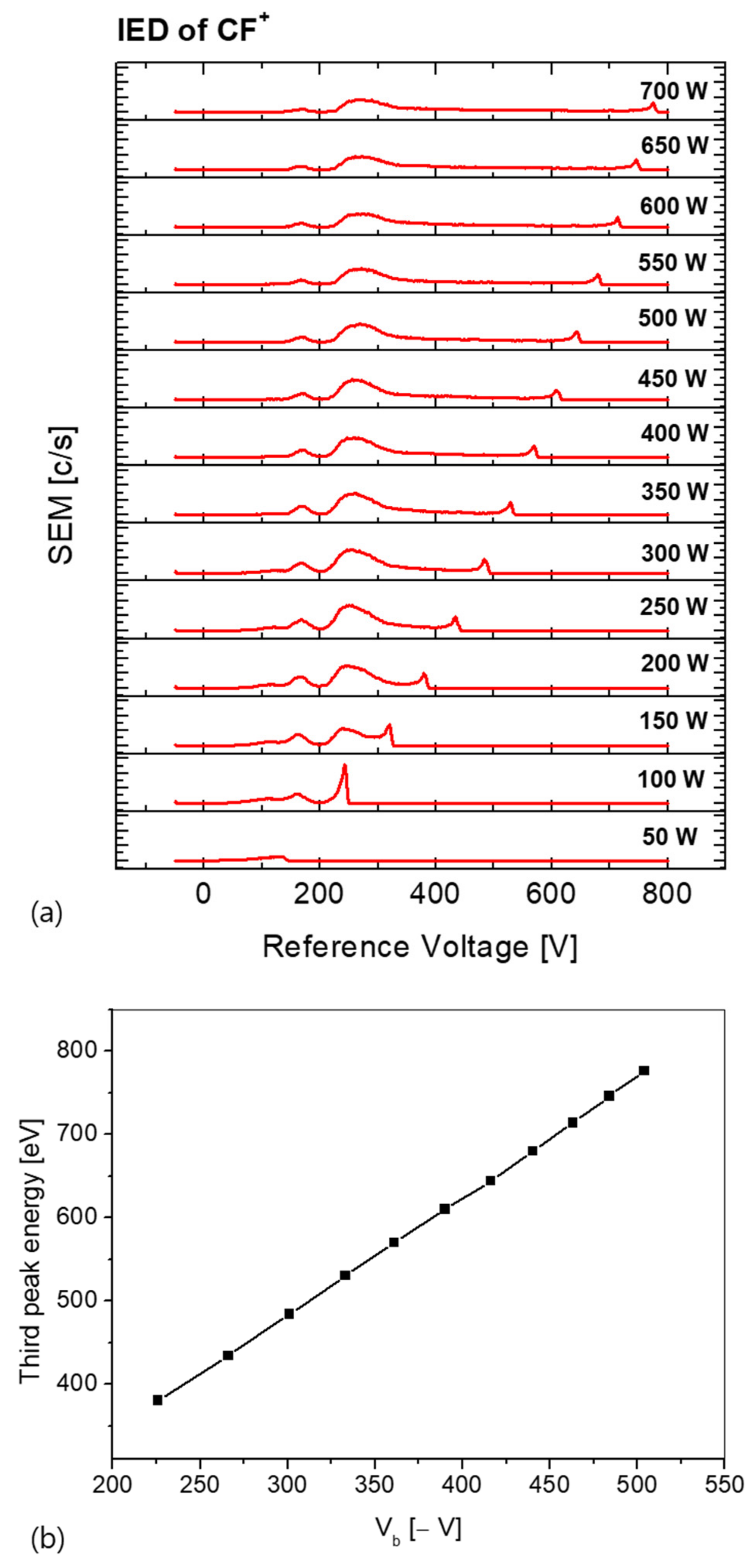
Figure 3a shows the ion energy distribution of a CF
+ ion incident on the RF-powered electrode as a function of the RF power. C
4F
8 (40 sccm)/Ar (80 sccm) was injected into the chamber at a ratio of 1:2 and the chamber pressure was maintained at 20 mTorr. The measured CF
+ ion energy distribution exhibits three dominant peaks. As the RF power increases, the energy of the third peak increases. However, the first and second peak energies remain constant. The change in the third peak energy was compared with the
Vb value. As shown in
Figure 3b, the change in the third energy peak increases linearly with the change in the
Vb value. As a result, the third energy peak is affected by the increase in the sheath potential due to the increase in the self-bias voltage, and therefore the energy of the ions incident on the substrate increases.
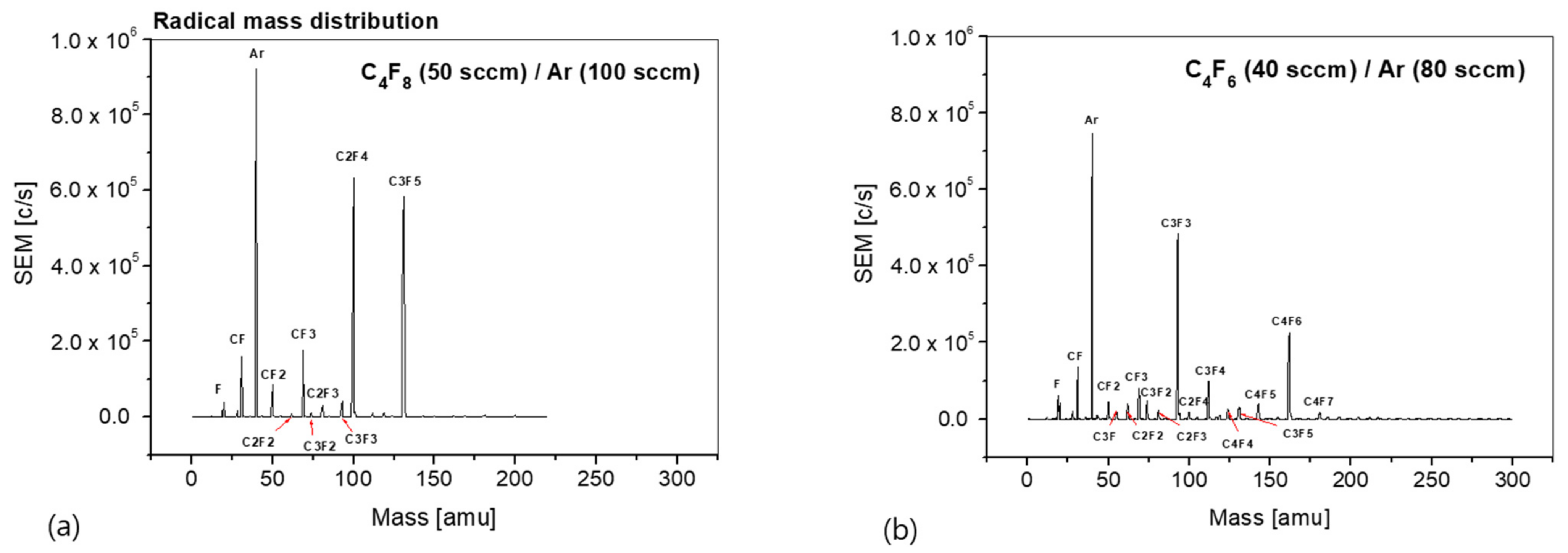
The radical mass distribution is an important parameter affecting the plasma process via chemical reactions during the etching or deposition process. Therefore, it is important to measure the species and density distributions of the radicals generated from a plasma. The radical mass distribution changes based on the process parameters, such as the operating pressure, RF power, process gas combination, and gas ratio. Based on these measurement results, it is possible to predict the types of radical species that are mainly involved in each process, and the process results can be predicted on the basis of the radical distribution.
Figure 4 shows the radical mass distribution obtained using the process gas. The gas injected into the chamber was a mixture of C
4F
8/Ar and C
4F
6/Ar. The gas ratio was fixed at 1:2, the total pressure was maintained at 20 mTorr, and the RF power was set to 300 W. The C
4F
8/Ar and C
4F
6/Ar plasmas exhibit different radical mass distributions depending on the reaction, such as ionization, dissociation, and electron attachment, and plasma parameters, such as the electron temperature and the chemical bond of the used gases. In the case of the C
4F
8/Ar plasma, the radical density was measured in the order of Ar, C
2F
4, C
3F
5, CF
3, CF, and CF
2. However, the parent molecule C
4F
8 was not measured. It appears to be mostly ionized and could not be measured. In the case of the C
4F
6/Ar plasma, the radical density was measured in the order of Ar, C
3F
3, C
4F
6, CF, C
3F
4, and CF
3. Unlike the C
4F
8/Ar plasma, many types of radicals were measured, and C
4F
7 radicals, which are heavier than the parent molecules, were also measured. This seems to be the result of ionization, dissociation, and attachment to the parent molecules in the plasma.
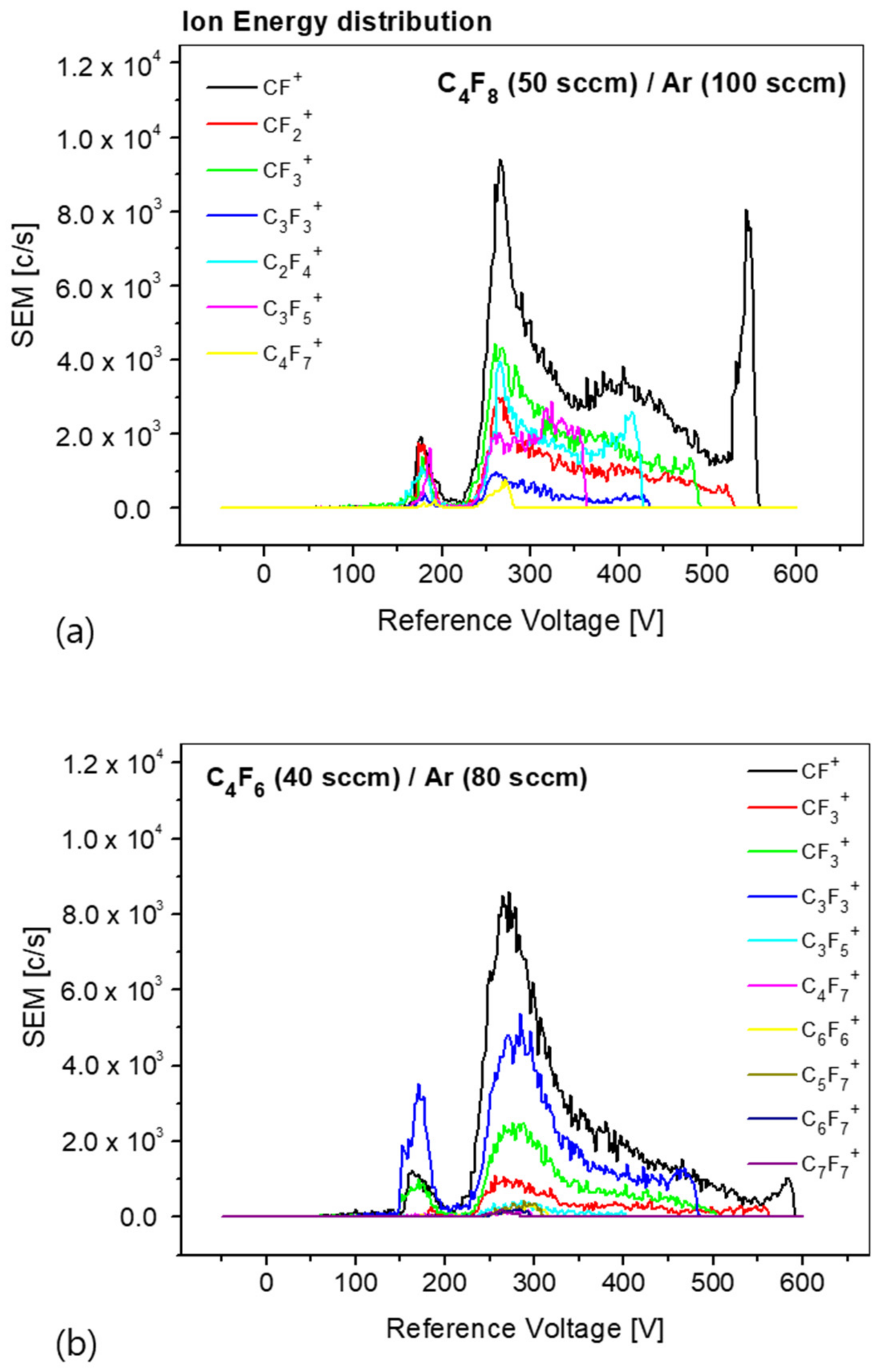
Figure 5 shows the results of the ion energy distribution measured under the same conditions as those employed for measuring the radical mass distribution. Comparing the ion energy distribution between the C
4F
8/Ar and C
4F
6/Ar plasmas, we find that the ion species, density, and energy distribution are different. The ion energy distribution shows that smaller ions have an energy distribution that includes high energy, as expressed in Equation (1). In addition, as the ion mass increases, the energy distribution mainly converges to approximately 270 eV. The causes are explained through further verification. The density of the ion species can be determined from the integral of the energy distribution of each ion species. In the case of C
4F
8/Ar plasma, the ion density was measured in the order of CF
+, CF
3+, C
2F
4+, CF
2+, and C
3F
5+. In the case of C
4F
6/Ar plasma, the order was CF
+, C
3F
3+, CF
3+, CF
2+, and C
3F
5+. In all the cases, the measurement differed from the radical density distribution. The measurement results of the energy and density distributions of the radicals and ions generated from the plasma using the process gases, e.g., in the case of C
4F
8/Ar and C
4F
6/Ar plasmas, will be helpful for understanding the process results.

 ,
, 