Article

Preparation and Characterization of PU/PET Matrix Gradient Composites with Microwave-Absorbing Function

1
School of Textile and Clothing, Nantong University, Nantong 226019, China
2
School of Mechanical Engineering, Southeast University, Nanjing 211189, China
3
School of Mechanical Engineering, Nantong University, Nantong 226019, China
*
Author to whom correspondence should be addressed.
Coatings 2021, 11(8), 982; https://doi.org/10.3390/coatings11080982
Submission received: 29 July 2021 / Revised: 13 August 2021 / Accepted: 17 August 2021 / Published: 18 August 2021

Abstract

:
In the field of microwave-absorbing materials, functional powder has always been the focus of research. In order to fabricate lightweight and flexible garment materials with microwave-absorbing function, the current work was carried out. Firstly, the general properties of polyurethane (PU) matrix composites reinforced with various microwave-absorbing powders were studied, and the carbon nanotubes (CNTs)/Fe3O4/PU film was proven to have the best general properties. Secondly, the needle-punched polyester (PET) nonwoven fabrics in 1 mm-thickness were impregnated into PU resin with the same composition of raw material as Fe3O4/CNTs/PU film, thereby the microwave-absorbing nonwovens with gradient structure were prepared. Moreover, the absorbing properties of the CNTs/Fe3O4/PU/PET gradient composites were tested and analyzed. Finally, the relationship between the mass ratio of CNTs and Fe3O4, and the microwave-absorbing properties was studied. The results show that the mass ratio of CNTs/Fe3O4 has a significant effect on the microwave-absorbing property of CNTs/Fe3O4/PU/PET. When the mass ratio of CNTs/Fe3O4 is 1:1, the prepared CNTs/Fe3O4/PU/PET gradient composite can achieve effective reflection loss in the range of more than 2 GHz in Ku-band (12–18 GHz), and the minimum reflection loss reaches −17.19 dB.

1. Introduction

At present, the rapid diffusion of electronic products produces a great number of radiations of electromagnetic waves around human beings [1,2]. Therefore, it is urgently needed to develop flexible microwave-absorbing textile with excellent microwave-absorbing properties to resist electromagnetic wave radiation and protect human health. A microwave-absorbing material is a kind of functional material that can absorb or attenuate the incident microwaves. It can convert or interfere with incident waves on the material surface by employing its inherent characteristics, to reduce the harm of electromagnetic wave radiation [3]. Microwave-absorbing functional powder has always been the focus of research in the field of microwave-absorbing materials. However, in the application of microwave absorbing functional powders, most of them are guided by the quarter theory, as while as taking into account the electromagnetic parameters of microwave absorbing materials [4]. As a result, the materials used for microwave absorption are often heavy and difficult to cut.
In recent years, due to the characteristics of low density, high conductivity, and high surface area, the carbon nanotube has gradually become a hot research spot in the field of microwave-absorbing composites [5,6,7]. However, microwave-absorbing composites filled with carbon nanotubes have obvious impedance mismatch problems, with relatively narrow effective absorption bandwidth. In order to solve the impedance mismatch problem, carbon nanotube is usually mixed with other fillers, such as Fe3O4 powder [8], graphite [9] or carbon fiber (CF) [10], which can not only obtain more balanced electromagnetic parameters, but also improve the microwave-absorbing properties. For example, Li et al. [11] enhanced the microwave-absorbing property of carbon nanotubes by adding Fe3O4 magnetic nanoparticle. The reflection loss of the optimized materials was less than −10 dB. Sandeep et al. [12] composed composite fillers of graphite and metal oxides, and prepared resin-based microwave-absorbing materials to improve the microwave-absorbing property of X-band. Wang et al. [13] prepared a flexible microwave-absorbing film based on graphene oxide/carbon nanotubes and Fe3O4 nanoparticles, which has been proven to have excellent microwave-absorbing properties in the range of 2–18 GHz.
Due to its special properties, Fe3O4 is often used as a filler to make composite materials with microwave absorption or electromagnetic shielding functions. Jacobo et al. [14] prepared a polyaniline (PANI)/Fe3O4 film composite with high conductivity, which indicated that the original performance of the materials can be improved after the Fe3O4 particles are filled. Yuvchenko et al. [15] studied the magnetic impedance of structured films in the presence of magnetic nanoparticles, which is helpful to the development of sensors for biomagnetic detection. The prepared non-woven fabric materials in our job with microwave absorption function can be used for human body wear, reduce the harm of electromagnetic waves to the human body, and has high application value in the medical field. The remarkable multi-modal function of magnetic nanoparticles used in our experiment, such as Fe3O4, is given by their size and morphology, which is very important for solving the challenge of slowing down the development of nano-biotechnology [16]. Aphesteguy et al. [17] used Fe3O4 to prepare medical magnetite magnetic nanoparticles and studied microwave resonant and zero-field absorption. Ansari et al. [18] summarized previous studies and believed that the magnetic iron oxide nanoparticles can be applied in the central nervous system. Kaczmarek et al. [19] used the magnetic nanoparticles for ultrasonic hyperthermia, which doubled the specific absorption rate.
It is well known that nonwovens are light, soft, and easy to process. As such, nonwoven fabrics have gradually come into the sight of researchers of microwave absorption. Bi etc. [20] assembled carbonyl iron and graphene aerogel onto nonwoven fabric, of which the widest efficient bandwidth covered 2.91–5.1 GHz and 10.99–18 GHz at the thickness of 6.0 mm, and the maximum RL is 22.3 dB. Egami etc. [21] coated polypyrrole on nonwoven fabric, and the results showed nonwoven sheets with extremely high frequencies absorption. However, the contribution of needle-punched fabric in the development of microwave absorption material has been rarely flagged up. Needle-punched fabric prosses irregular 3D pores formed by randomly tangled staple fibers, which endows them with various microwave absorption performance when loaded with different functional fillers.
In current study, the graphite, Fe3O4, carbonyl iron powder (CIP), carbon fiber, and carbon nanotubes were selected as the microwave-absorbing powders, and the PU was selected as the matrix to construct the microwave-absorbing materials. Through the comparison of properties such as tensile strength, adhesion, and antistatic ability, we found that the CNTs/Fe3O4/PU film has the best general performance. Furthermore, CNTs/Fe3O4/PU/PET gradient composites with the framework of needle-punched PET nonwoven fabric were prepared. In addition, its microwave-absorbing properties on the X-band and Ku-band were tested. The main contributions of our work are as follows. First, we proposed the preparation methods of microwave absorbing film and PU/PET matrix gradient composites. Moreover, the experimental tests proved that Fe3O4 and CNTs have outstanding general performance, suitable for the preparation of wearable non-woven fabrics with microwave-absorbing function. Finally, the microwave-absorbing performance of the gradient composite was tested, and it was proven that both the Fe3O4 content and the gradient structure have a great influence on the microwave absorption effect.

2. Materials and Methods

2.1. Materials and Specimen Preparation

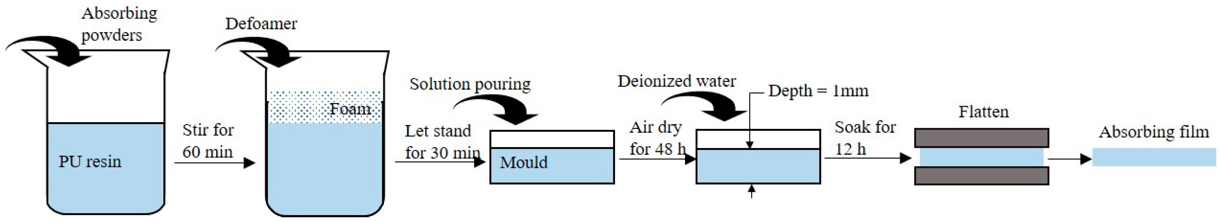
2.1.1. Microwave-Absorbing Film

The preparation scheme of the microwave-absorbing film used in the general performance test is shown in Table 1, in which the thickness of the prepared microwave-absorbing wet film is 1 mm. In the single factor process of microwave-absorbing film, the waterborne polyurethane (PU, 601C type, Hefei Tairuike New Material Technology CO., Ltd, Hefei, China), thickener agent (Hefei Tairuike New Material Technology CO., Ltd, Hefei, China), and defoamer agent (X-690 type, Guangzhou Hongtai New Material CO., Ltd, Guangzhou, China) was used as matrix, and the graphite (20–80 mesh, Lingshou Zhanteng Mineral Products Processing Factory, Shijiazhuang, China), carbon fiber (CF, 500 mesh, Changzhou Hengfeng Nano Technology Co., Ltd, Changzhou, China), Fe3O4 (500 nm, with irregular shape, Qinghe Tuopu Metal Material Co., Ltd, Xingtai, China), and carbonyl iron powder (CIP, C913576 type, Shanghai Macklin Biochemical Co., Ltd, Shanghai, China) were used as the microwave-absorbing powders, respectively. The fillers mentioned above all have the functions of microwave absorption and electromagnetic shielding, which are often used in the related experiments. In the two-factors process of microwave-absorbing film, the combination of carbon nanotube (CNT, length > 5 µm, Changzhou Hengfeng Nano Technology Co., Ltd, Changzhou, China) and the absorbing powders in single factor process group were used as the microwave-absorbing powder, respectively. As contrast, pure PU film was processed as the control group.
The preparation process of microwave-absorbing film is shown in Figure 1. First, the 100 wt.% waterborne PU resin and 0.3 wt.% thickener were added to the beaker and stirred at a speed of 500 r/min for 10 min. Then, the microwave-absorbing powders were added to the waterborne PU and stirred at a speed of 800 r/min for 60 min, until the absorbing powders were dispersed. Next, the defoamer was added to the beaker and stirred at 500 r/min for 5 min to disperse the defoamer uniformly, and then let it stand for 30 min to defoam. After the foam disappears, it was poured into a glass mold with 1 mm depth. After air-dried for 48 h, the deionized water was added. After being soaked for 12 h, the coagulated film was removed and flattened with a pair of plates to obtain a microwave-absorbing film.

2.1.2. Microwave-Absorbing Impregnated Nonwoven Fabric

Employing needle-punched polyester (PET) nonwoven fabric in 1 mm-thickness (120 g/m2, Yiwu Piccolo Electronic Commerce Co., Ltd, Yiwu, China) as a framework, the microwave-absorbing impregnated nonwoven fabric with gradient structure was prepared.
The preparation process of microwave-absorbing impregnated nonwoven fabric is shown in Figure 2. The preparation process of the absorbing solution was consistent with the preparation process of the microwave-absorbing film. After the foam disappeared, the absorbing solution was poured into a glass mold. The non-woven fabric substrate with a size of 30 cm × 30 cm was gently rinsed with deionized water to avoid errors due to sample deformation. Then, the non-woven fabric substrate was put into a constant temperature drying oven, and dried at a temperature of 65 °C for 24 h. After it was completely dried, it was taken out and naturally regained moisture for 24 h. Moreover, the bottom of the PET needle-punched nonwoven fabric was brought into contact with the absorbing solution in the glass mold to perform impregnation treatment. After standing for 24 h, a microwave-absorbing impregnated cloth with gradient structure was obtained.
The physical pictures of the prepared microwave-absorbing impregnated nonwoven fabric are shown in Figure 3.

2.2. Test Equipment and Methods

Desktop scanning electron microscopy (ZEISS Gemini SEM 300 type, Carl Zeiss AG, Oberkochen, Germany) was used to observe the samples’ microstructures. The sample of the microwave-absorbing film was cut into 5 mm × 5 mm rectangles.
Material testing machine (3119-609 type, Instron company, Boston, MA, USA) was used to measure the tensile property of microwave-absorbing film. According to the standard (ISO 527-3:1995) [22], the film was cut into 100 mm × 15 mm rectangles. In the tensile test, the fracture at a tensile rate of 50 mm/min had the maximum tensile force and elongation. The thickness of the film can be measured by fabric thickness tester (YG(B)141D type, Wenzhou Darong Textile Instrument Co., Ltd, Wenzhou, China).
The prepared uniform coating was scraped on the cleaned and dried glass plate with 14-coating rod at a constant speed to produce a 32 μm thick coating. QFH-A Cross-Cut suit film adhesion tester is adopted in accordance with ASTM D3359-09 standard test method [23]. By cutting and penetrating the lattice image of coating, 100 small squares with a size of 2 mm × 2 mm were obtained, and then glued with 3M600 pressure-sensitive adhesive paper. Then, one end of the tape was quickly torn off from the direction of 90°. The magnifying glass was used to observe the area of falling squares. The percentage of the area of falling squares to the total surface area was evaluated by coating adhesion level, which was divided into 0 to 5, with 5 as the worst.
According to the standards JJG920-2017 [24], optical density meter (LS117 type, Shenzhen Linshang Technology Co., Ltd, Shenzhen, China) was used to test the optical density and transmissivity of microwave-absorbing film.
The surface resistance tester (VICTOR 385 type, Shenzhen Yisheng Shengli Technology Co., Ltd, Shenzhen, China) was used to test the resistance and impedance of microwave-absorbing film. During the test, the sensor meter was placed on the surface of microwave-absorbing film and cannot be in contact with other objects. It should be noted that the tests were performed multiple times.
According to the bow reflection method the measurement methods for the reflectivity of radar absorbing material (GJB 2038A-2011) [25], the vector network analyzer (AV3672C, China Electronics Technology Instrument Co., Ltd, Qingdao, China) was used to measure the microwave-absorbing property of the materials. The test bands were X-band and Ku-band. The frequency ranges were 8.2–12.4 GHz and 12–18 GHz. The sample size was 30 cm × 30 cm.

3. Experiment Results and Discussion

3.1. General Performance
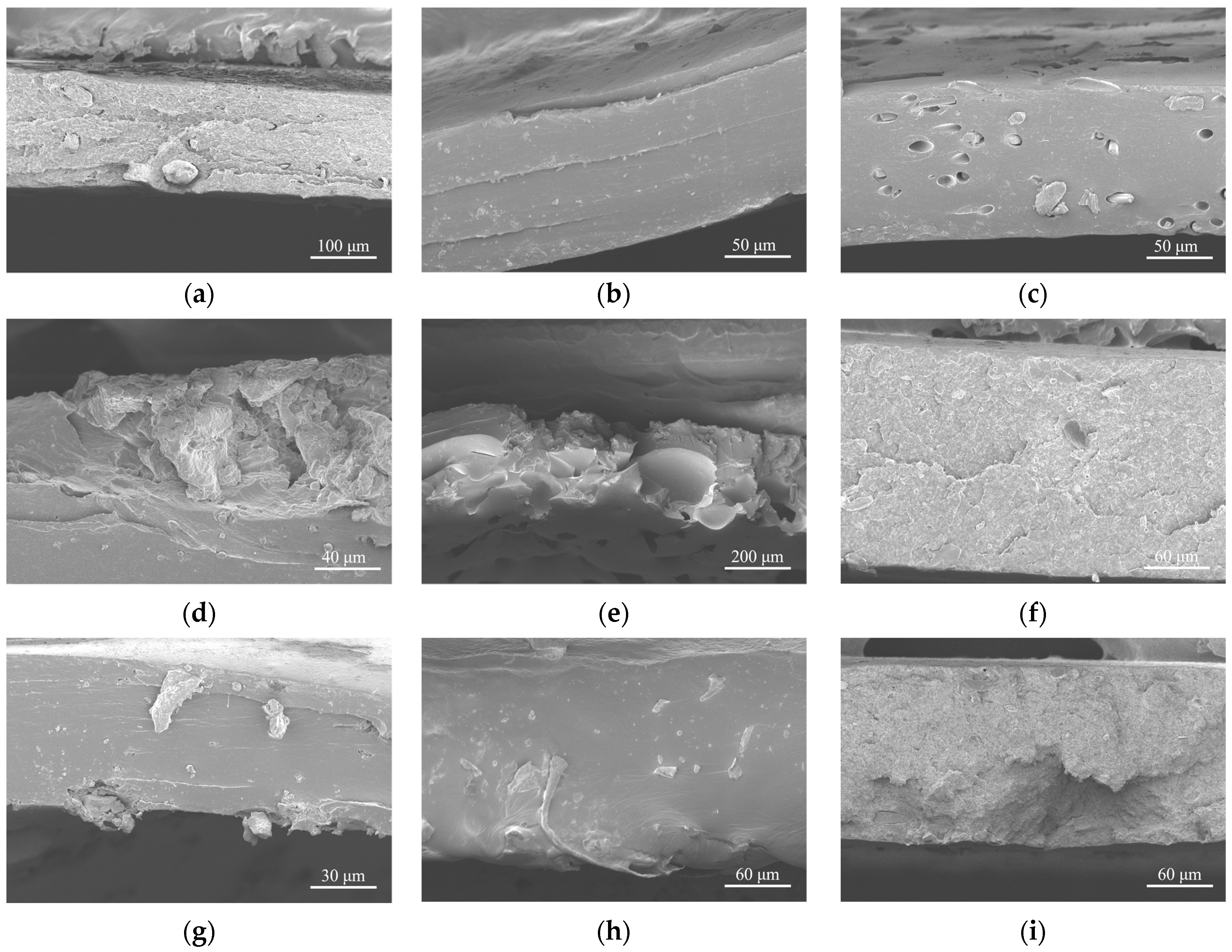
The general performance of films has a great effect on the stability of the matrix. Therefore, single-factor experiments on general performance of functionalized PU films and pure PU were conducted to pick out a kind of PU film, with good general performance, for the process of microwave-absorbing compound materials.

3.1.1. SEM Images

The SEM images of different microwave-absorbing films are shown in Figure 4. In the process of taking the SEM images, the extra high tension (EHT) of PU film was set to 2.0 kV. In order to obtain clear images, the working distance (WD) was continuously changed with the test pieces. Figure 4a shows a pure PU film as a control group, with a flat surface. Figure 4b presents a PU film doped with graphite. Due to the sheet structure of graphite, it is easy to see some swellings formed by the lapping of sheets on the surface of the film. Since the graphite sheets are very easy to slip, smaller particles will also appear during the preparation process. Figure 4c shows a PU film mixed with CFs. It is obvious that the directions along the length of the CFs in the film distribute at random in three-dimensional space. Figure 4d shows a PU film doped with Fe3O4 powder. Some bumps result from irregularly shaped Fe3O4 appearing on the surface of the film. Figure 4e presents a PU film mixed with CIP. Except for some micro-powders, there are also dozens of microns holes on the surface of the film, indicating that the CIP causes exothermic reaction, during the high-speed mechanical stirring process, generating gas and heat. This is because CIP powder has great activity and can catalyze the exothermic reaction between CO and CO2, which will further affect the stability of CIP in the later film formation process. The CIP in the film formation process is affected by heat and continues to release CO, thereby forming many micro-holes in the film. Figure 4f is a PU film doped with graphite and CNTs. The three-dimensional lap shape formed by the graphite flake structure is still obvious, but the size of such three-dimensional lap structure is significantly reduced, in the situation of coexisting of graphite flake and CNTs, comparing with Figure 4b. Figure 4g shows a PU film mixed with CFs and CNTs. The CFs are scattered in a straight or diagonal manner, and the curled CNTs are randomly distributed both on the surface of the CFs and in the film. Therefore, the distribution of CNTs can be approximately regarded as the approximate linear distribution along the CFs and the three-dimensional distribution in the film. Compared with the surface of other functional PU film, part of the three-dimensional space of the CNTs is lost, which is unfavorable for the loss and absorption of microwaves. Figure 4h shows a PU film doped with Fe3O4 powders and CNTs. Irregular Fe3O4 powders and tubular CNTs can be found randomly distributed in the three-dimensional space of the film, which are conducive to the absorption of microwaves. Figure 4i shows a PU film doped with CIP and CNTs. There are no obvious micropores on the surface of the film. It is considered that the presence of CNTs inhibits the exothermic reaction of the CIP, so there are no obvious pores on the surface.

3.1.2. Tensile Property

Functional PU films can not only bear forces, but also protect the functional phases from external force damage, resulting in a stable function performance. Therefore, thin film materials with good tensile properties are the prerequisite for the process of microwave-absorbing impregnated nonwoven fabrics with excellent microwave-absorbing function.
Figure 5 shows the tensile strength and breaking elongation rate of pure and functional PU films filled with different fillers. In control group F1, the tensile strength and elongation of pure PU is 3.15 MPa and 12.29%, respectively. Single-factor process groups F2–F5 are the tensile strength and elongation of the functional PU films loading graphite, CFs, nano Fe3O4 powder and CIP, respectively. It can be found that the loading of graphite, CFs and nano Fe3O4 powder in 1.5 wt.%, keeping the PU resin in 100 wt.%, can improve the tensile strength of PU film. The reason is that graphite, CFs and nano Fe3O4 powder have stable performance in high-speed mechanical stirring process in water, and can induce better crystallization of PU, thereby enhancing the tensile strength of PU film. However, the loading of CIP reduces the tensile strength of CIP/PU film. Also, the CIP has been found to be so unstable in high-speed mechanical stirring process in water that it releasees a lot of heat, which impairs the formation of PU film and eventually leads to a significant decrease in tensile strength. It is worth mentioning that the loading of graphite can significantly improve the tensile strength and breaking elongation of PU film to 3.15 MPa and 12.29%, respectively. In contrast, although the addition of CFs can significantly increase tensile strength, it cannot significantly improve breaking elongation.
The two-factors process groups F6–F9 come from the single-factor process groups F2–F5, into which CNTs are incorporated. The experimental results show that the tensile strength of the two-factors process groups is more than twice that of the control group and is nearly double that of the corresponding sample in the single-factor process groups, which indicates that the loading of CNTs improves the tensile strength of functional PU film. Especially, when Fe3O4 combined with CNTs dispersed in PU film, the tensile strength of the film reaches a maximum of 9.35 MPa. The breaking elongations of almost all two-factors process groups increase by about 2–20 times higher than that of the control group, but that of CIP is almost the same as that of the control group. In experiment F9, the combination of CIP and CNTs in PU film makes the breaking elongation of the film achieve a maximum of 267.46%.
The fractograph of pure and functional PU films loaded with varied fillers is observed with SEM images, as shown in Figure 6. As can be seen from the figure, the cross-sections of pure PU film (Figure 6a), graphite/CNTs/PU film (Figure 6f) and CIP/CNT/PU film (Figure 6i) are relatively similar and are all uneven, containing a great number of fragments. It is believed that these films fracture slowly, and a large deformation occurs. Furthermore, the cross-sections of graphite/PU film (Figure 6b), CFs/PU film (Figure 6c), Fe3O4/PU film (Figure 6d), CFs/CNTs/PU film (Figure 6g), and Fe3O4/CNTs/PU film (Figure 6h) look neat, indicating that brittle fractures have occurred, and the fillers make a significant contribution to the enhancement of the strength of the PU films. The CIP/PU film (Figure 6e) is special. Its fracture is relatively neat, scattered with holes. On the fracture, the marks of multiple brittle fracture are very obvious. It is thought that in the fabrication of CIP/PU film, a lot of gas and heat is generated, which results in stress concentration along the film. It is harmful to the tensile performance.

3.1.3. Adhesion

The adhesion can examine the performance of coating film. Only when a microwave-absorbing film and its substrate have good adhesion do they not fall off easily and exert their microwave-absorbing properties on the basis of a complete film coverage.
As can be seen from Table 2, the adhesion level of control group F1 is level 3. In the single-factor process group, the adhesion levels of F2 and F3 are both level 1, and the adhesion levels of F4 and F5 are both level 2. The adhesion levels in the two-factors process group are greater than or equal to level 3. When the amount of PU is 100%, part of the coating will fall off. After adding a single microwave-absorbing filler such as graphite, CFs, nano Fe3O4 powder and CIP, the adhesion of coating is improved. Especially, the loading of graphite or CFs will help the adhesion of coating achieve the best level. When the CNTs are added, the adhesion level of coating film increases. Moreover, large patches of films peel off. Through comparison, it can be seen that the adhesion levels of the coating films loaded with CNTs is higher than or equal to those without CNTs. Considering the high strength of CNTs, the length dispersion is basically along the plane of the film. The effect of surface tension will weaken the dispersion of functional particles, such as CNTs, micro powders, microfibers, and so on, at the interface, resulting in the weakening of adhesion performance. When the CNTs meet flake graphite, the dispersion characteristics of CNTs will affect the adhesion performance of the flake graphite, resulting in the decline of the overall adhesion performance. When the CNTs meet CIP powder, the presence of CNTs inhibits the exothermic reaction of the CIP, so there are no obvious pores both on the surface and in the film. CNTs and CIP powder are uniformly dispersed in the film, but due to the effect of surface tension, there are few opportunities for them to emerge, resulting in a decrease in the adhesion performance.

3.1.4. Optical Density and Transmittance

During the experiment, we found that the addition of fillers will reduce the transparency of the film. The microwave absorption film prepared by us is mainly used for human body wear, and the change of transparency will have a certain impact on the use occasion of the composite. Therefore, we performed qualitative measurements on the parameters of optical density (OD) and transmittance. The test results of OD and transmittance of pure and functional PU films are shown in Figure 7. The LS117 optical density meter used 380–760 nm whole white light for the test of OD and transmittance, which complied with the international commission on illumination (CIE) photopic function standard.
It is observed from the Figure 7 that the optical density of the pure PU film is the smallest (0.04), and the transmittance is the largest (94.97). When such functional phases as graphite, carbon fiber, nano Fe3O4 powder, and carbonyl iron are loaded in the films in one-factor process groups, respectively (experiment number F2–F5), the optical densities of the films increase slightly, remaining at a low level (less than 0.1), while the transmittances of those one-factor process group films decrease to 83%–90%. In the two-factors process groups, a certain amount of carbon nanotubes is loaded in the films, combining with the unchanged amount of powder filler in one-factor process group films. This results in the rapid rise of optical density of functional PU films, which are all above 1, while the transmittance drops sharply. In other words, the addition of CNTs will seriously reduce the transparency of the microwave-absorbing film, because the SWCNTs inside the CNTs will absorb light [26].

3.1.5. Antistatic Property

The fillers in this experiment play an important role in absorbing and shielding electromagnetic waves [27,28]. The results of surface resistance test reflect the influence of the fillers on the antistatic property of the functional PU films, as shown in Table 3. The surface resistance of control group F1 is in the order of 109 Ω. F2–F5 are the single-factor process groups. Among them, the surface resistance of F2 with graphite is the smallest, which is in the order of 109 Ω, while the surface resistances of F3, F4 and F5 all reach the order of 1011 Ω. The antistatic properties of these four kinds of films in the single-factor process groups are between conductors and insulators, reaching the order of a semiconductor, which is similar to pure PU film. In the two-factors process groups F6–F9, incorporating of CNTs into the single-factor process groups significantly reduces the order of magnitude of surface resistance, achieving 104–105 Ω. The antistatic properties of these four kinds of films in two-factors process groups all reach the level of a conductor. The CNTs possess excellent conductivity [29], showing good electrical properties even in a semiconductor matrix.

3.1.6. Selection of Filling Scheme

Based on the analysis of the above experimental results, it can be found that the combination of Fe3O4 and CNTs can effectively improve the mechanical properties of microwave-absorbing film. For example, the tensile strength reaches 9.35 MPa, which is 193.15% higher than that of control group F1, and 79.46% higher than that of single-factor process group F3. In addition, Fe3O4/CNTs/PU film also performs best in the properties of adhesion, transmission and antistatic in the two-factors process group.
A good general performance is the basis of microwave-absorbing performance. Therefore, Fe3O4/CNTs/PU film (F8) with excellent general performance is selected to impregnate nonwoven fabric in 1 mm thickness to carry out further research on microwave-absorbing properties.

3.2. Microwave-Absorbing Property

3.2.1. Gradient Absorbing Structure

The cross-section is observed with SEM, of the Fe3O4/CNTs/PU/PET microwave-absorbing impregnated nonwoven fabric. As shown in Figure 8a, in the normal direction of the impregnated nonwoven fabric surface, the resin wrapped densely on the lower surface of the fiber web. At the same time, the resin on the upper surface is so rare that several single fibers can be easily made out.
In the lower surface of the fiber web, that is, the side contacting the impregnating liquid, the resin is densely distributed, and the fibers are wrapped by the resin.
In the normal direction of the impregnated non-woven fabric, the resin distributes in a gradient manner, which is thick and weighty at the bottom, while thin and insubstantial on the top. It is undoubtedly that such a gradient structure could enhance the penetration of microwaves on the outer surface, and the absorption and loss inside the matrix, as shown in Figure 8b.

3.2.2. Influence of Mass Ratio of Fe3O4/CNTs on Microwave-Absorbing Property

With regard to the fact that Fe3O4/CNTs/PU film (F8) shows excellent general performance, the PET nonwoven fabric is impregnated in the PU slurry with the same composition of raw material as the Fe3O4/CNTs/PU film. Also, considering the mass ratio of Fe3O4 and CNTs maybe have a great influence on microwave-absorbing property of Fe3O4/CNTs/PU/PET, another two impregnated PET nonwoven fabric with varied mass ratios of Fe3O4 and CNTs were investigated, as shown in Table 4. During the experiment, the content of CNTs remained unchanged, and the content of Fe3O4 increased exponentially to 0.75, 1.5, and 2.25 wt.%, respectively. Figure 9 shows the SEM micrograph and particle size distribution of Fe3O4 powders. It can be seen from Figure 9 that the Fe3O4 particles have irregular shapes, but most of the particles are spherical. The diameter of the Fe3O4 particles is mainly concentrated below 500 nm, accounting for 96.25% of the total number of particles, and the average diameter of the particles is 341.82 nm. Figure 10 shows the XRD patterns of Fe3O4. The diffraction peaks appear at 2θ of 18.34°, 30.14°, 35.50°, 37.10°, 43.12°, 53.48°, 57.10°, 62.58°, and 74.01°. Calculated from Bragg’s Law [17], the corresponding crystal face index is (111), (220), (311), (222), (400), (422), (511), (440), and (533). It is found that the XRD pattern is basically consistent with the characteristic of peak position and peak intensity of the cubic crystal system Fe3O4 (JCPDS 99-0073) standard card.
The bow reflection method is employed to observe the microwave-absorbing performances of Fe3O4/CNTs/PU/PET matrix gradient composites, with varied mass ratio of Fe3O4 and CNTs, in the ranges of 8.2–12.4 GHz and 12–18 GHz.
Figure 11 shows the results of the absorbing performance test. The microwave-absorbing performance of these three samples face down in the frequency range of 8.2 to 12.4 GHz are as follows. First, Fe3O4/CNTs/PU/PET matrix gradient composite made from 1.5 wt.% CNTs, 1.5 wt.% Fe3O4, and 100 wt.% PU shows the highest maximum reflection loss, which is −2.12 dB. Secondly, Fe3O4/CNTs/PU/PET matrix gradient composite composed of 1.5 wt.% CNTs, 2.25 wt.% Fe3O4, and 100 wt.% PU resin ranks second, with the maximum reflection loss of −1.62B. Third, Fe3O4/CNTs/PU/PET matrix gradient composite containing 1.5 wt.% CNTs, 0.75 wt.% Fe3O4 and 100 wt.% PU resin has the lowest maximum reflection loss, which is −1.00 dB.
The microwave-absorbing performance of these three samples in the 12–18 GHz frequency band are as follows. The Fe3O4/CNTs/PU/PET matrix gradient composite composed of 1.5 wt.% CNTs, 1.5 wt.% Fe3O4 and 100 wt.% PU resin has a maximum reflection loss of −17.19 dB. In addition, the microwave-absorbing performance of the Fe3O4/CNTs/PU/PET matrix gradient composite containing 1.5 wt.% CNTs, 2.25 wt.% Fe3O4 and 100 wt.% PU resin and that of 1.5 wt.% CNTs, 0.75 wt.% Fe3O4 and 100 wt.% PU resin are both −3 dB, with minute differences.
The results suggest that the reflection loss of Fe3O4/ CNTs/ PU/ PET gradient composites can be improved, when carbon nanotubes and Fe3O4 are in the mass ratio of 1:1. Particularly, a satisfied efficient reflection loss can be achieved in the frequency range of more than 2 GHz in Ku-band, and the minimum reflection loss reaches −17.19 dB. If the mass ratio is too large or too small, no efficient microwave-absorbing performance is shown. It is considered that impedance match is achieved when the mass ratio of CNTs and Fe3O4 is 1:1, the microwave-absorbing reagent can consume most of the electromagnetic waves. If the mass ratio of dielectric and magnetic medium is too large or too small, the impedance mismatches, resulting in poor microwave-absorbing performance. It seems that the key in the development of the thin and lightness of microwave-absorbing materials is just to solve the impedance matching problem among conductor, dielectric and magnetic medium.
To verify this speculation, the microwave-absorbing performance of these three samples face up in the frequency bands of both X-band and Ku-band are also displayed, seen in Figure 12a,b. Both figures show no efficient reflection loss. However, with the mass ratio of Fe3O4 increasing from 0.75 to 2.25 wt.%, the reflection loss is improved. So, keeping the absorbers the same, variation of the injected direction of electromagnetic wave onto a gradient composite leads to a significant difference in their electromagnetic absorbing performance. It is obvious that the structural parameters of micro objects also play a key role in impedance matching. It can be inferred that impedance matching, which impacts greatly on microwave-absorbing materials, depends not only on the electromagnetic performances of conductors, dielectric and magnetic mediums, but also on their macro structures’ parameters.

4. Conclusions

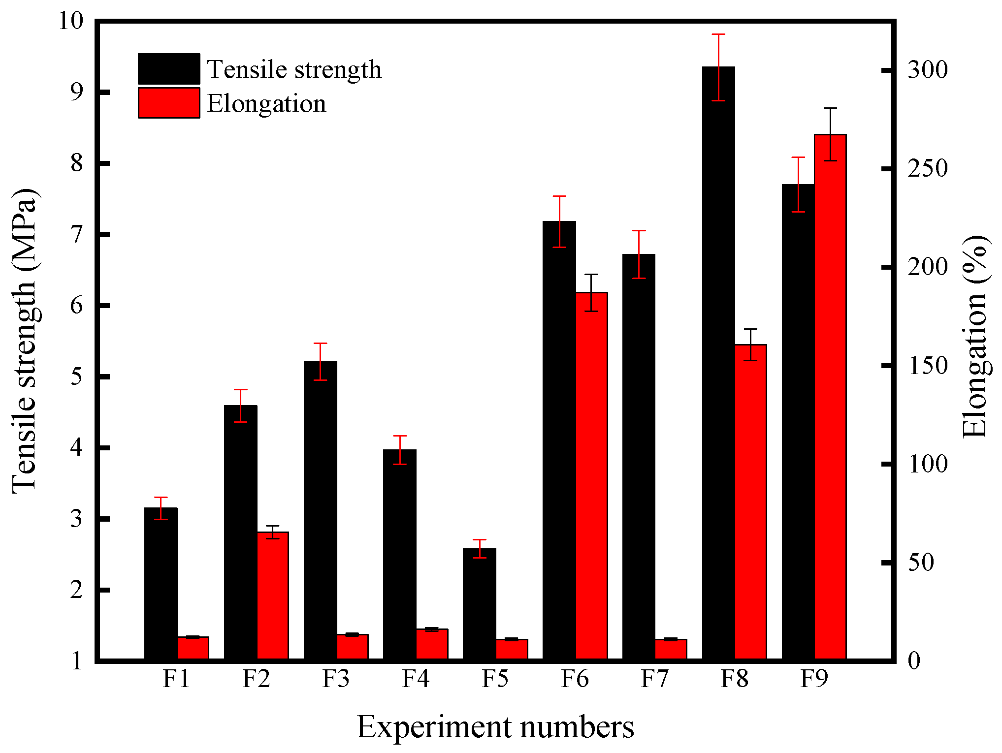
  • Microwave-absorbing powder can significantly improve a film’s tensile property. When Fe3O4 and CNTs are combined in usage of a filler, the tensile strength of the film reaches a maximum value of 9.35 MPa. When CIP and CNTs are mixed as fillers, the breaking elongation of the film reaches the maximum, which is 267.46%. CNTs can increase the adhesion level of coating film, while the other microwave-absorbing powders will help enhance the coating adhesion. The antistatic property of films in the single-factor process groups is similar to that of pure PU film, which is similar to semiconductor. The loading of CNTs in PU film significantly reduces the surface resistance, so that the functional PU films loaded with CNTs is similar to conductor.
  • The combination of Fe3O4 and CNTs can effectively improve the mechanical properties of PU film. For example, the tensile strength is 193.15% higher than that of the control group F1, and 79.46% higher than that of the single factor process group F3.
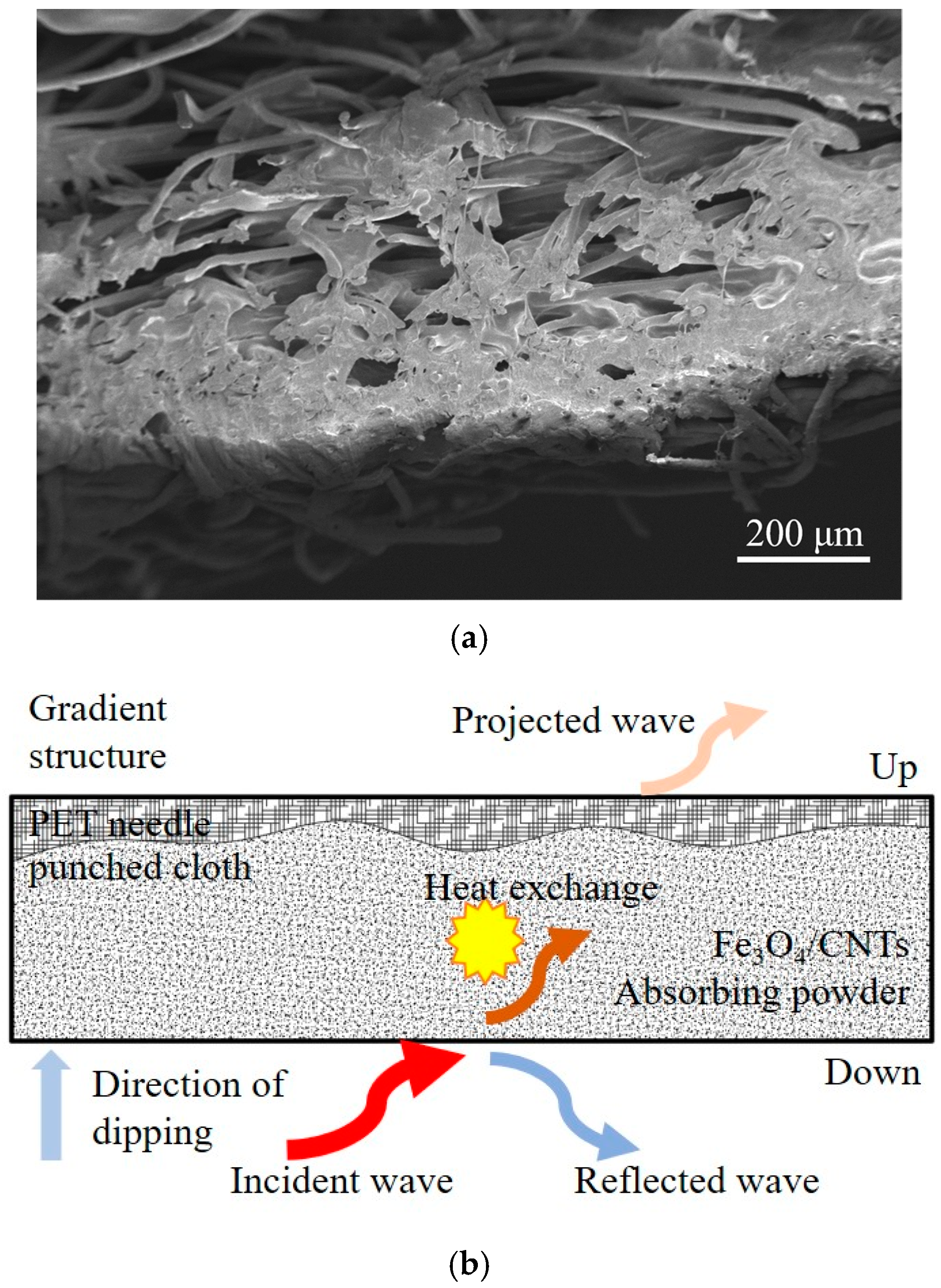
  • The mass ratio of CNTs and Fe3O4 has a significant impact on the microwave-absorbing properties of PU/PET matrix gradient composites. In the Ku-band, when the mass ratio of CNTs and Fe3O4 is 1:1, the PU/PET matrix microwave-absorbing composite in the thickness of 1 mm has a maximum reflection loss of −17.19 dB. When the mass ratio of CNTs and Fe3O4 is more than or less than 1:1, PU/PET matrix gradient composites show poor microwave-absorbing performance.
  • The Fe3O4/CNTs/PU/PET matrix gradient composite was easily fabricated with needle punched nonwoven and shown notable electromagnetic absorbing performance, indicating the great prospects of gradient nonwovens in electromagnetic absorbing fields.
  • The Fe3O4/CNTs/PU/PET matrix gradient composite was easily fabricated with needle punched nonwoven and shown notable absorbing performance, indicating the great prospects of gradient nonwovens in electromagnetic absorbing fields. Our current work tries to clarify the macro performance of different PU/PET matrix gradient composites with microwave-absorbing function. Further research involving the relationship between different structure forms at micro-level, meso-level and macro-level will be conducted in the future.

Author Contributions

Conceptualization, W.G.; methodology, R.Z. and R.L.; validation, J.Z.; formal analysis, J.Z.; resources, W.G.; writing-original draft, R.Z. and J.L.; writing-review and editing, W.G. and J.Z.; investigation, R.L.; visualization, J.Z.; supervision, W.G. All authors have read and agreed to the published version of the manuscript.

Funding

This research was funded by Jiangsu Overseas Research and Training Program for University Prominent Young and Middle-aged Teachers and Presidents (Grant No. 148), and the Innovative Project of Nantong University Students (Grant No. 143).

Institutional Review Board Statement

Not applicable.

Informed Consent Statement

Not applicable.

Data Availability Statement

Not applicable.

Conflicts of Interest

The authors declare no conflict of interest.

References

  1. Wanasinghe, D.; Aslani, F.; Ma, G. Electromagnetic shielding properties of carbon fibre reinforced cementitious composites. Constr. Build. Mater. 2020, 260, 120439. [Google Scholar] [CrossRef]
  2. Yang, J.; Liao, X.; Wang, G.; Chen, J.; Guo, F.; Tang, W.; Wang, W.; Yan, Z.; Li, G. Gradient structure design of lightweight and flexible silicone rubber nanocomposite foam for efficient electromagnetic interference shielding. Chem. Eng. J. 2020, 390, 124589. [Google Scholar] [CrossRef]
  3. Jia, Z.; Lan, D.; Lin, K.; Qin, M.; Kou, K.; Wu, G.; Wu, H. Progress in low-frequency microwave absorbing materials. J. Mater. Sci. Mater. Electron. 2018, 29, 17122–17136. [Google Scholar] [CrossRef]
  4. Zhan, J.; Yao, Y.; Zhang, C.; Li, C. Synthesis and microwave absorbing properties of quasione-dimensional mesoporous NiCo2O4 nanostructure. J. Alloys Compd. 2014, 585, 240–244. [Google Scholar] [CrossRef]
  5. Gao, Y.; Gao, X.; Li, J.; Guo, S. Improved microwave absorbing property provided by the filler’s alternating lamellar distribution of carbon nanotube/carbonyl iron/poly (vinyl chloride) composites. Compos. Sci. Technol. 2018, 158, 175–185. [Google Scholar] [CrossRef]
  6. Zheng, X.; Hu, Q.; Wang, Z.; Nie, W.; Wang, P.; Li, C. Roll-to-roll layer-by-layer assembly bark-shaped carbon nanotube/Ti3C2Tx MXene textiles for wearable electronics. J. Colloid Interface Sci. 2021, 602, 680–688. [Google Scholar] [CrossRef]
  7. Savi, P.; Giorcelli, M.; Quaranta, S. Multi-walled carbon nanotubes composites for microwave absorbing applications. Appl. Sci. 2019, 9, 851. [Google Scholar] [CrossRef] [Green Version]
  8. Song, X.; Li, X.; Yan, H. Preparation and microwave absorption properties of MWCNTs/Fe3O4/NBR composites. Diam. Relat. Mater. 2019, 100, 107573. [Google Scholar] [CrossRef]
  9. Zhao, T.; Jin, W.; Ji, X.; Yan, H.; Jiang, Y.; Dong, Y.; Yang, Y.; Dang, A.; Li, H.; Li, T.; et al. Synthesis of sandwich microstructured expanded graphite/barium ferrite connected with carbon nanotube composite and its electromagnetic wave absorbing properties. J. Alloys Compd. 2017, 712, 59–68. [Google Scholar] [CrossRef] [Green Version]
  10. Singh, S.K.; Akhtar, M.J.; Kar, K.K. Hierarchical carbon nanotube-coated carbon fiber: Ultra, lightweight, thin, and highly efficient microwave absorber. ACS Appl. Mater. Interfaces 2018, 10, 24816–24828. [Google Scholar] [CrossRef]
  11. Li, N.; Huang, G.; Li, Y.; Xiao, H.; Feng, Q.; Hu, N.; Fu, S. Enhanced microwave absorption performance of coated carbon nanotubes by optimizing the Fe3O4 nanocoating structure. ACS Appl. Mater. Interfaces 2017, 9, 2973–2983. [Google Scholar] [CrossRef]
  12. Singh, S.K.; Akhtar, M.J.; Kar, K.K. Impact of Al2O3, TiO2, ZnO and BaTiO3 on the microwave absorption properties of exfoliated graphite/epoxy composites at X-band frequencies. Compos. Part B Eng. 2019, 167, 135–146. [Google Scholar] [CrossRef]
  13. Wang, L.; Jia, X.; Li, Y.; Yang, F.; Zhang, L.; Liu, L.; Ren, X.; Yang, H. Synthesis and microwave absorption property of flexible magnetic film based on graphene oxide/carbon nanotubes and Fe3O4 nanoparticles. J. Mater. Chem. A 2014, 2, 14940–14946. [Google Scholar]
  14. Jacobo, S.E.; Aphesteguy, J.C.; Anton, R.L.; Schegoleva, N.N.; Kurlyandskay, G.V. Influence of the preparation procedure on the properties of polyaniline based magnetic composites. Eur. Polym. J. 2007, 43, 1333–1346. [Google Scholar] [CrossRef]
  15. Yuvchenko, A.A.; Lepalovskii, V.N.; Vas’kovskii, V.O.; Safronov, A.P.; Volchkov, S.O.; Kurlyandskaya, G.V. Magnetic impedance of structured film meanders in the presence of magnetic micro- and nanoparticles. Tech. Phys. 2014, 59, 230–236. [Google Scholar] [CrossRef]
  16. Zamani Kouhpanji, M.R.; Stadler, B.J.H. A guideline for effectively synthesizing and characterizing magnetic nanoparticles for advancing nanobiotechnology: A review. Sensors 2020, 20, 2554. [Google Scholar] [CrossRef] [PubMed]
  17. Aphesteguy, J.C.; Jacobo, S.E.; Lezama, L.; Kurlyandskaya, G.V.; Schegoleva, N.N. Microwave resonant and zero-field absorption study of doped magnetite prepared by a co-precipitation method. Molecules 2014, 19, 8387–8401. [Google Scholar] [CrossRef] [Green Version]
  18. Ansari, S.A.M.K.; Ficiarà, E.; Ruffinatti, F.A.; Stura, I.; Argenziano, M.; Abollino, O.; Cavalli, R.; Guiot, C.; D’Agata, F. Magnetic iron oxide nanoparticles: Synthesis, characterization and functionalization for biomedical applications in the central nervous system. Materials 2019, 12, 465. [Google Scholar] [CrossRef] [Green Version]
  19. Kaczmarek, K.; Hornowski, T.; Dobosz, B.; Józefczak, A. Influence of magnetic nanoparticles on the focused ultrasound hyperthermia. Materials 2018, 11, 1607. [Google Scholar] [CrossRef] [Green Version]
  20. Bi, S.; Tang, J.; Wang, D.J.; Su, Z.A.; Hou, G.L.; Li, H.; Li, J. Lightweight non-woven fabric graphene aerogel composite matrices for assembling carbonyl iron as flexible microwave absorbing textiles. J. Mater. Sci. Mater. Electron. 2019, 30, 17137–17144. [Google Scholar] [CrossRef]
  21. Egami, Y.; Yamamoto, T.; Suzuki, K.; Yasuhara, T.; Higuchi, E.; Inoue, H. Stacked polypyrrole-coated non-woven fabric sheets for absorbing electromagnetic waves with extremely high frequencies. J. Mater. Sci. 2012, 47, 382–390. [Google Scholar] [CrossRef]
  22. ISO 527-3:1995. Plastics-Determination of Tensile Properties Part 3: Test Conditions for Films and Sheets; International Organization for Standardization: Geneva, Switzerland, 1995. [Google Scholar]
  23. ASTM D3359-09. Standard Test Methods for Measuring Adhesion by Tape Test; American Society for Testing and Materials: West Conshohocken, PA, USA, 2009. [Google Scholar]
  24. JJG920-2017. Diffuse Transmission Visual Densitometers; National Optical Metrology Technical Committee: Beijing, China, 2017. (In Chinese) [Google Scholar]
  25. GJB 2038A-2011. The measurement Methods for Reflectivity of Radar Absorbing Material; General Assembly Electronic Information Basic Department: Beijing, China, 2011. (In Chinese) [Google Scholar]
  26. Jiang, S.; Hou, P.; Chen, M.; Wang, B.; Sun, D.; Tang, D.; Jin, Q.; Guo, Q.; Zhang, D.; Du, J.; et al. Ultrahigh-performance transparent conductive films of carbon-welded isolated single-wall carbon nanotubes. Sci. Adv. 2018, 4, eaap9264. [Google Scholar] [CrossRef] [PubMed] [Green Version]
  27. Wang, D.; Wu, Z.; Li, F.; Gan, X.; Tao, J.; Yi, J.; Liu, Y. A combination of enhanced mechanical and electromagnetic shielding properties of carbon nanotubes reinforced Cu-Ni composite foams. Nanomaterials 2021, 11, 1772. [Google Scholar] [CrossRef] [PubMed]
  28. Kim, H.-J.; Kim, S.-H.; Park, S. Effects of the carbon fiber-carbon microcoil hybrid formation on the effectiveness of electromagnetic wave shielding on carbon fibers-based fabrics. Materials 2018, 11, 2344. [Google Scholar] [CrossRef] [PubMed] [Green Version]
  29. Ulloa-Castillo, N.A.; Martínez-Romero, O.; Hernandez-Maya, R.; Segura-Cárdenas, E.; Elías-Zúñiga, A. Spark plasma sintering of aluminum-based powders reinforced with carbon nanotubes: Investigation of electrical conductivity and hardness properties. Materials 2021, 14, 373. [Google Scholar] [CrossRef]
Figure 1. The preparation process of the microwave-absorbing film.
Coatings 11 00982 g001
Figure 2. Preparation process of microwave-absorbing impregnated nonwoven fabric.
Coatings 11 00982 g002
Figure 3. Physical images: (a) PET needle punched nonwoven fabric; (b) Microwave-absorbing impregnated nonwoven fabric.
Coatings 11 00982 g003
Figure 4. The SEM images of pure and functional PU films: (a) F1 (WD = 8.2 mm, EHT = 2.0 kV); (b) F2 (WD = 8.2 mm, EHT = 2.0 kV); (c) F3 (WD = 8.3 mm, EHT = 2.0 kV); (d) F4 (WD = 8.1 mm, EHT = 2.0 kV); (e) F5 (WD = 8.2 mm, EHT = 2.0 kV); (f) F6 (WD = 8.1 mm, EHT = 2.0 kV); (g) F7 (WD = 7.6 mm, EHT = 2.0 kV); (h) F8 (WD = 8.2 mm, EHT = 2.0 kV); (i) F9 (WD = 8.2 mm, EHT = 2.0 kV).
Coatings 11 00982 g004
Figure 5. Tensile strength and elongation of pure and functional PU films loaded with different fillers.
Coatings 11 00982 g005
Figure 6. The SEM images of fractograph of pure and functional PU films: (a) F1 (WD = 5.7 mm, EHT = 2.0 kV); (b) F2 (WD = 6.9 mm, EHT = 2.0 kV); (c) F3 (WD = 5.9 mm, EHT = 2.0 kV); (d) F4 (WD = 7.0 mm, EHT = 2.0 kV); (e) F5 (WD = 6.9 mm, EHT = 2.0 kV); (f) F6 (WD = 5.9 mm, EHT = 2.0 kV); (g) F7 (WD = 6.1 mm, EHT = 2.0 kV); (h) F8 (WD = 7.1 mm, EHT = 2.0 kV); (i) F9 (WD = 7.0 mm, EHT = 2.0 kV).
Coatings 11 00982 g006
Figure 7. Test results of optical density and transmittance of pure and of functional PU films.
Coatings 11 00982 g007
Figure 8. Structure and principle of PU/PET matrix microwave-absorbing gradient composites: (a) SEM image of cross-section of PU/PET matrix microwave-absorbing gradient composites (WD = 7.4 mm, EHT = 2.0 kV); (b) Principle of PU/PET matrix microwave-absorbing gradient composites.
Coatings 11 00982 g008
Figure 9. The SEM micrograph and particle size distribution of Fe3O4 powders (a) SEM image (WD=9.2 mm, EHT=5.0 kV); (b) particle size distribution.
Coatings 11 00982 g009
Figure 10. The XRD pattern of Fe3O4.
Coatings 11 00982 g010
Figure 11. The influence of different mass ratio of CNTs and Fe3O4 on microwave-absorbing performance of Fe3O4/CNTs/PU/PET gradient composites, with composites face down: (a) 8.2–12.4 GHz; (b) 12–18 GHz.
Coatings 11 00982 g011
Figure 12. The influence of different mass ratio of CNTs and Fe3O4 on microwave-absorbing performance of Fe3O4/CNTs/PU/PET gradient composites, with composites face up: (a) 8.2–12.4 GHz; (b) 12–18 GHz.
Coatings 11 00982 g012
Table 1. Preparation scheme of microwave-absorbing film for the general performance test.
Experiment NumberGroupAbsorbing Powder 1/(wt.%)Absorbing Powder 2/(wt.%)PU/(wt.%)
F1Control group--100
F2Single factor process groupGraphite/1.5-100
F3CFs/1.5-100
F4Fe3O4/1.5-100
F5CIP/1.5-100
F6Two-factors process groupGraphite/1.5CNTs/1.5100
F7CFs/1.5CNTs/1.5100
F8Fe3O4/1.5CNTs/1.5100
F9CIP/1.5CNTs/1.5100
Table 2. Test results of the adhesion of the pure and functional PU films.
Experiment NumberLevel
F13
F21
F31
F42
F52
F64
F73
F83
F94
Table 3. Test results of the impedance and surface resistance of the pure and functional PU films.
Experiment NumberSurface Resistance (Ω)Antistatic Property
F1109Semiconductor
F2109Semiconductor
F31011Semiconductor
F41011Semiconductor
F51011Semiconductor
F6104Conductor
F7105Conductor
F8105Conductor
F9104Conductor
Table 4. Experimental scheme for the ratio of Fe3O4/CNTs.
Experiment NumberCNTs/(wt.%)Fe3O4/(wt.%)PU/(wt.%)
F101.52.25100
F111.51.5100
F121.50.75100
Publisher’s Note: MDPI stays neutral with regard to jurisdictional claims in published maps and institutional affiliations.

