Article

The Effects of Substrate Bias on the Properties of HfC Coatings Deposited by RF Magnetron Sputtering

1
School of Materials Science and Chemical Engineering, Harbin Engineering University, Harbin 150001, China
2
Key Laboratory of Super Light Material and Surface Technology Ministry of Education, Harbin Engineering University, Harbin 150001, China
3
Institute of Surface/Interface Science and Technology, Harbin Engineering University, Harbin 150001, China
4
College of Mechanical and Vehicle Engineering, Chongqing University, Chongqing 400030, China
5
Chongqing Gearbox Co., Ltd., Chongqing 401122, China
6
Military Representative Bureau of PLA Navy Armaments Department in Guangzhou Area, Guangzhou 440100, China
*
Author to whom correspondence should be addressed.
Coatings 2021, 11(8), 963; https://doi.org/10.3390/coatings11080963
Submission received: 28 May 2021 / Revised: 6 August 2021 / Accepted: 10 August 2021 / Published: 13 August 2021

Abstract

:
In the paper, by using radio frequency (RF) magnetron sputter technology, the HfC coating grew on a 316L stainless steel substrate in an Ar atmosphere at various substrate bias voltages from 0 to −200 V. From the X-ray diffraction (XRD) and transmission electron microscopy (TEM) experiments, the HfC coatings were well crystallized and (111) preferential growth had been successfully obtained by controlling bias voltage at −200 V. Nanoindentation experimental results for the prepared HfC coatings indicated that they possessed the maximum nanohardness due to the formation of the (111) orientation. The results of electrochemical measurements displayed that 316L stainless steel (316L) coated with the HfC coatings had better corrosion resistance than bare 316L. With the bias voltage increasing to −200 V, adhesion of the 316L substrate with the HfC coating could be greatly improved, as well as corrosion resistance. The antithrombogenicity of the HfC coatings was identified by platelet adhesive and hemolytic ratio assay in vitro. It was shown that the hemocompatibility of coated 316L had been improved greatly compared with bare 316L and the HfC coatings possessed better antithrombogenicity with the bias voltage elevating above −150 V.

1. Introduction

Biomaterials have been applied to modern medicinal fields widely, such as orthopedy, dentistry, cardiology, and ophthalmology [1,2,3]. AISI medical 316L stainless steel (316L) is the perfect metal material in artificial joints of surgical implants, intravascular stents, and artificial heart valve replacements due to its outstanding mechanical performance [4]. However, its low hardness, poor wear resistance, and bad hemocompatibility, as well as a tendency to corroding under a body fluid environment, limit its applications [5,6,7]. Many studies have demonstrated that 316L cardiovascular implants, such as stents, create toxic Ni, Cr, and Mo metal ions after long-term implantation in vivo that can break down the body’s cells or activate platelets, which in turn release their granules to promote coagulation, change shape, and become sticky to aggregate and plug small vascular holes [8,9,10]. A solution to this is fabricating coatings with special properties and better blood compatibility on 316L. The use of transition metal nitrides, carbides, oxides, or oxynitrides has been suitable for such industrial and commercial applications; thus a lot of compounds with excellent corrosion resistance, low friction coefficient, good hemocompatibility, etc., have been determined, for example, NbN [11], TiN [12], ZrN [13], TiC [14], TiO2 [15], ZrO2 [16], and TiON [17].
Transition metal hafnium has strengths, such as excellent corrosion resistance, high strength, and good biocompatible performance [18]. To study its osteogenesis and biocompatibility, Matsuno et al. [19] implanted titanium, hafnium, niobium, tantalum, and rhenium in the subcutaneous tissue of rats. It was found that the osteogenesis and biocompatibility of hafnium were the best. However, the literature presented that hafnium underwent pitting corrosion on its surface; its mechanical properties and biocompatibility would obviously become poor [20]. Compared with a pure transition metal, transition metal carbides also have many excellent properties, such as superior mechanical properties, high melting temperature, good wear resistance, and outstanding corrosion resistance, and have been widely used as hard coatings, anti-ablation coatings, wear-resistant coating, etc. [21,22,23]. Hafnium carbide coating with the highest melting point (3890 °C) is one of these carbides used as a high-temperature-resisting coating owing to its chemical inertness, low oxygen diffusion coefficient, and excellent chemical compatibility with carbon/carbon composites [24,25,26]. In addition, Braic et al. [27] reported that (TiZrNbHfTa)C coating containing C and Hf elements possesses good synthesis performances, such as a low friction coefficient, high hardness, superior corrosion resistance, and good biocompatible properties. Taking into account the above, HfC coatings could possess many advantages; up to now, no report has been given on the deposition of HfC coatings on 316L stainless steel to improve its corrosion resistance, wear, and hemocompatibility. Therefore, this paper presented an investigation whose purpose was to prepare HfC coatings on 316L and determined the bias voltage’s effect on the coatings’ structural, mechanical, and tribological behaviors; corrosion resistance; and hemocompatibility.

2. Experimental Details

The coatings’ deposition process was carried out in a multi-target sputtering magnetron. This system allowed the in situ multilayer formation. For the hafnium carbide (HfC) coatings, a Hf-C composite target was used; 316L substrates were subjected to a surface-cleaning process in an ultrasound system. Prior to the start of the depositions, a base pressure of 2 × 10⁻⁵ Pa was generated. During preparation, a working pressure of 0.35 Pa was used in an argon atmosphere of 20 sccm at 25 °C, and an RF power of 120 W was applied on the target. The 316L substrates were exposed to bias voltages (0, −100, −150, and −200 V).
The chemical bonding state was determined by X-ray photoelectron spectroscopy (XPS) (VG Science Ltd., London, UK) with AlKɑ radiation. The specimens were sputter-etched for 10 min with a 5 keV Ar+ ion beam. The crystallographic structure determination of the HfC coating was analyzed by XRD (PANalytical, Almelo, Upper Ethel, Netherlands,) using a Cu-Kα radiation source with a wavelength of λ = 1.5405 Å. For transmission electron microscopy (TEM) (JEOL Ltd., Akishima, Tokyo, Japan) studies, was used to determine the microstructure of the coatings. The coatings’ thickness and wear scratch images were obtained by using SEM (FEI, Hillsboro, OR, USA). For surface morphology quantitative characterization (roughness), atomic force microscopy (AFM) was used with AJ-IIIa device (Aijian Nanotechnology Inc. Shanghai, China). Mechanical characterization by nanoindentation was done using a Hysitron device (Hysitron, Minneapolis, MN, USA). From the nanoindentation test, the load as a function of displacement curves was obtained for the three coatings. The hardness and elastic modulus were determined with the Oliver–Pharr method. Tribological characterization was carried out by using a U MT-2 tribotester (Center for Tribology Inc., CA, USA) with a 3 mm diameter WC + 6% Co ball as a counterpart material; the applied load was 100 g, and the feed rate was 50 cm/min.
Corrosion resistance characterization was carried out in phosphate buffer solution (PBS) at pH 7.4 at a temperature of 37 ± 1 °C. It was prepared by adding 8 g of NaCl, 0.2 g of KCl, 1.44 g of Na2HPO4, and 0.24 g of KH2PO4 to 1 L of water used as a solvent. The corrosion behavior of coated 316L was investigated by a three-electrode system including a working electrode (sample), a counter-electrode (platinum electrode), and a reference electrode (saturated calomel electrode). The measurement of the polarization curve was carried out by CHI660E (Chenhua Instrument Co. Ltd. Shanghai, China) equipment with a scan range of −0.5 V (vs. SCE) to 0.5 V (vs. SCE) and a resolution of 1 mV/s. The measurement of Nyquist diagrams was performed in a frequency sweep range of 100 kHz–0.01 Hz, and a 10 mV sinusoidal voltage amplitude was loaded to the sample and reference electrode. By Tafel extrapolation methods, the corrosion current densities and corrosion potentials of coated 316L were obtained from the polarization curves and their mean value and standard deviation were calculated, too.
The hydrophilicity of samples was determined using FTA 200 contact angle goniometer equipment from contact-angle measurements. A 0.4 mL droplet was dripped on to HfC-coated 316L, and the contact angle measurement was conducted 30 s later. For the contact angle (θ), the disperse component ( γ S V d ) and polar component ( γ S V p ) of solid surface energy, and the disperse component ( γ L V d ) and polar component ( γ L V p ) of liquid surface energy in the solid–liquid system, the following Equation (1) can be used.
γ L V   ( 1 + c o s θ ) = 2 γ L V p γ S V p + 2 γ L V d γ S V d
According to Young’s formula, interfacial tensions (γSL) can be obtained by following Equation (2).
γ S V = γ S L + γ L V cos θ
where γLV and γSV are the liquid surface energy and the solid surface energy, respectively [28].
Hemolysis and platelet adhesion tests were conducted in order to evaluate the blood compatibility of coated 316L. The method reported in the literature [29] was used to evaluate hemolytic, and percentage hemolysis was obtained from the following Equation (3).
H e m o l y s i s   ( % ) = A A 0 A A 100 × 100 ,
where A is the absorbance of the sample, A0 is the absorbance of the negative control, and A100 is the absorbance of the positive control. The overall course of the platelet adhesion test was as follows. Platelet-rich plasma was obtained by centrifuging whole blood for 30 min at constant velocity, and then it was attached to the coatings’ surface. Satisfying SEM micrographs were obtained by using glutaraldehyde as the fixing solution, drying with CO2 and the gold-sprayed method [30].

3. Results and Analysis

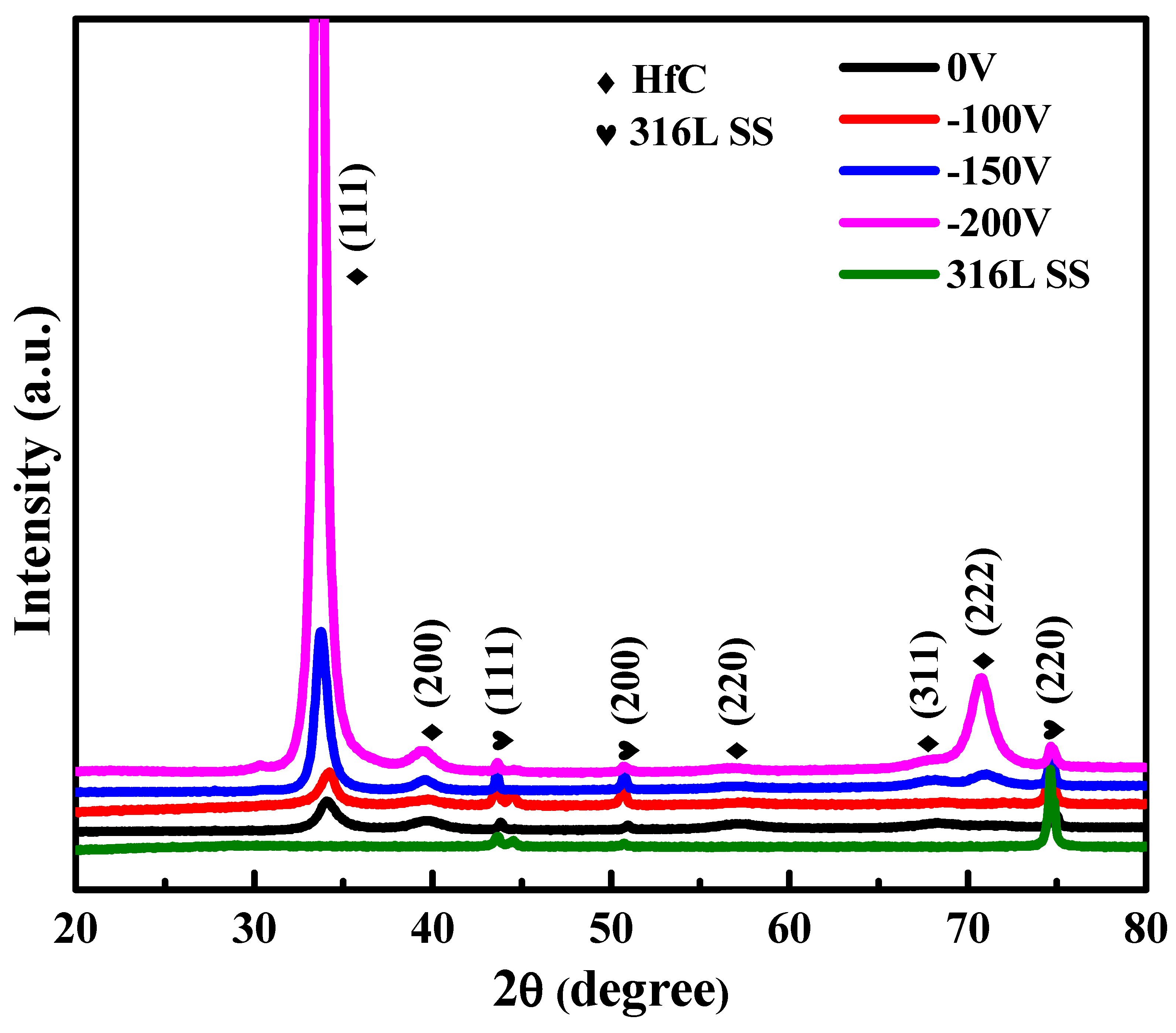
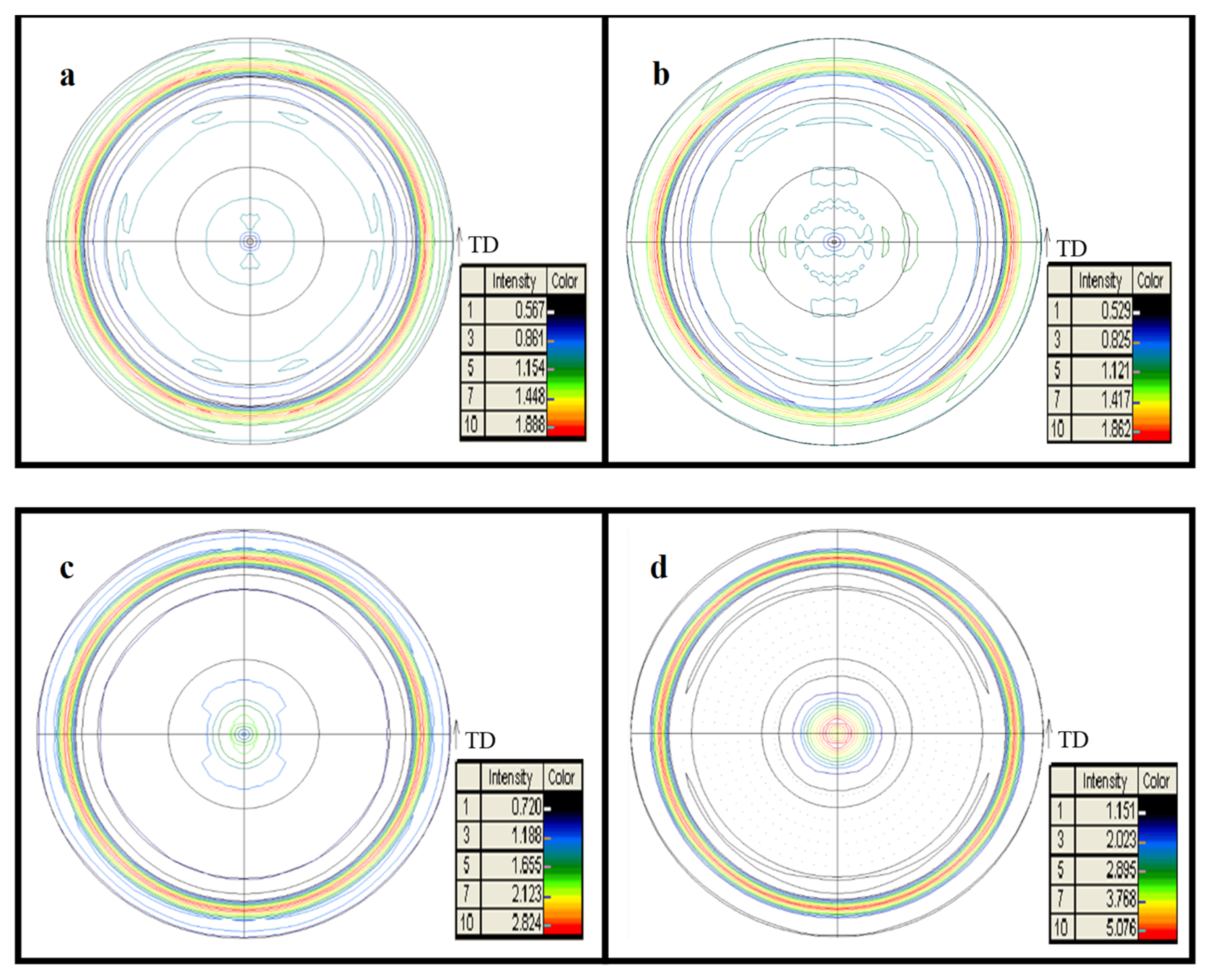
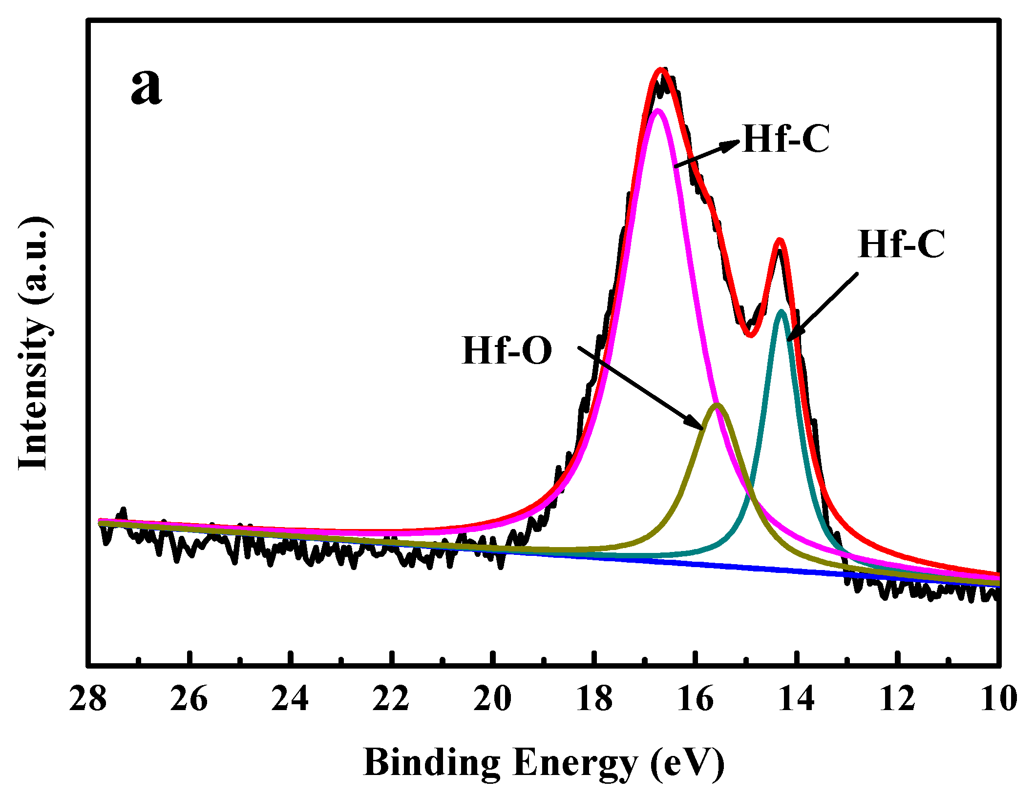
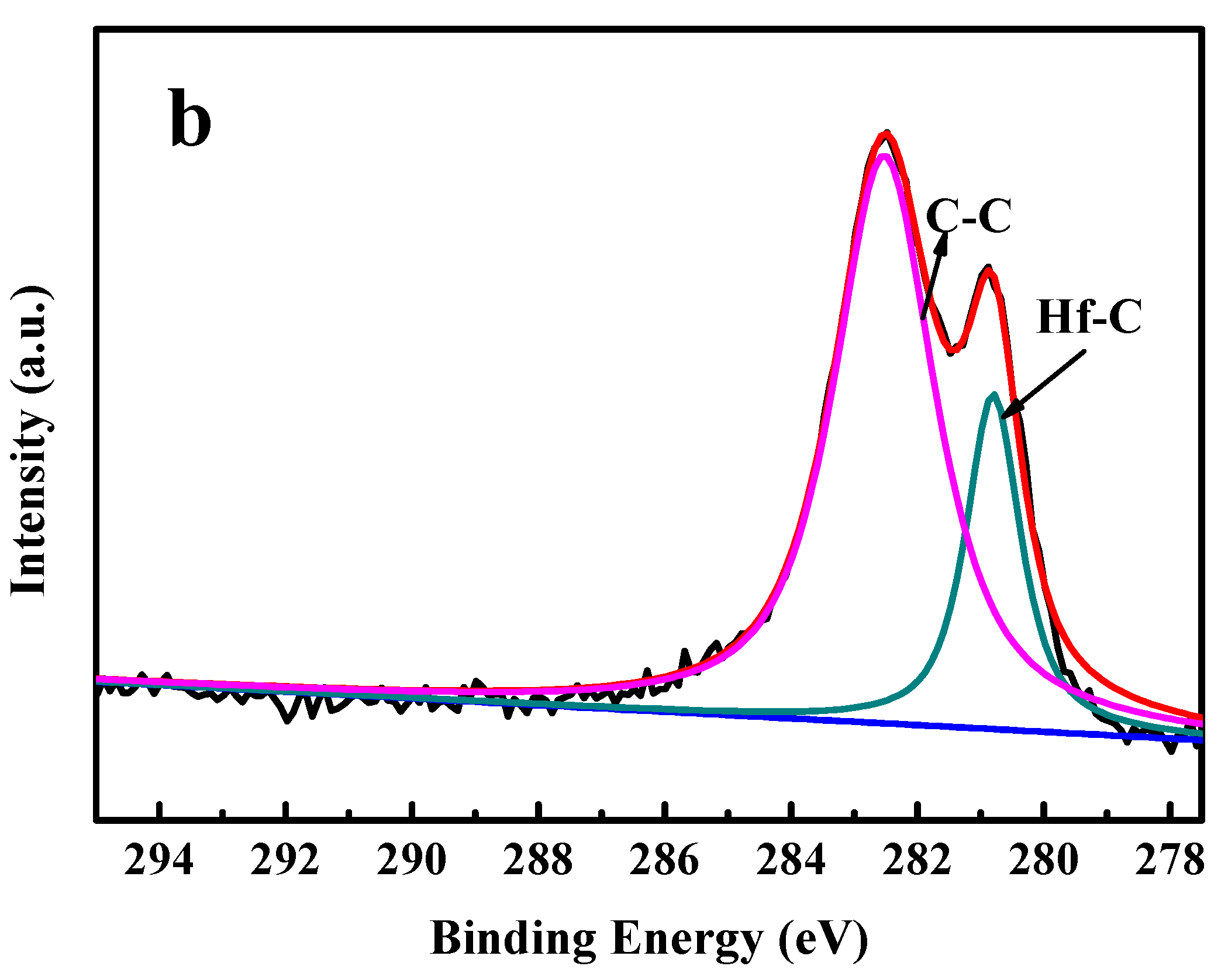
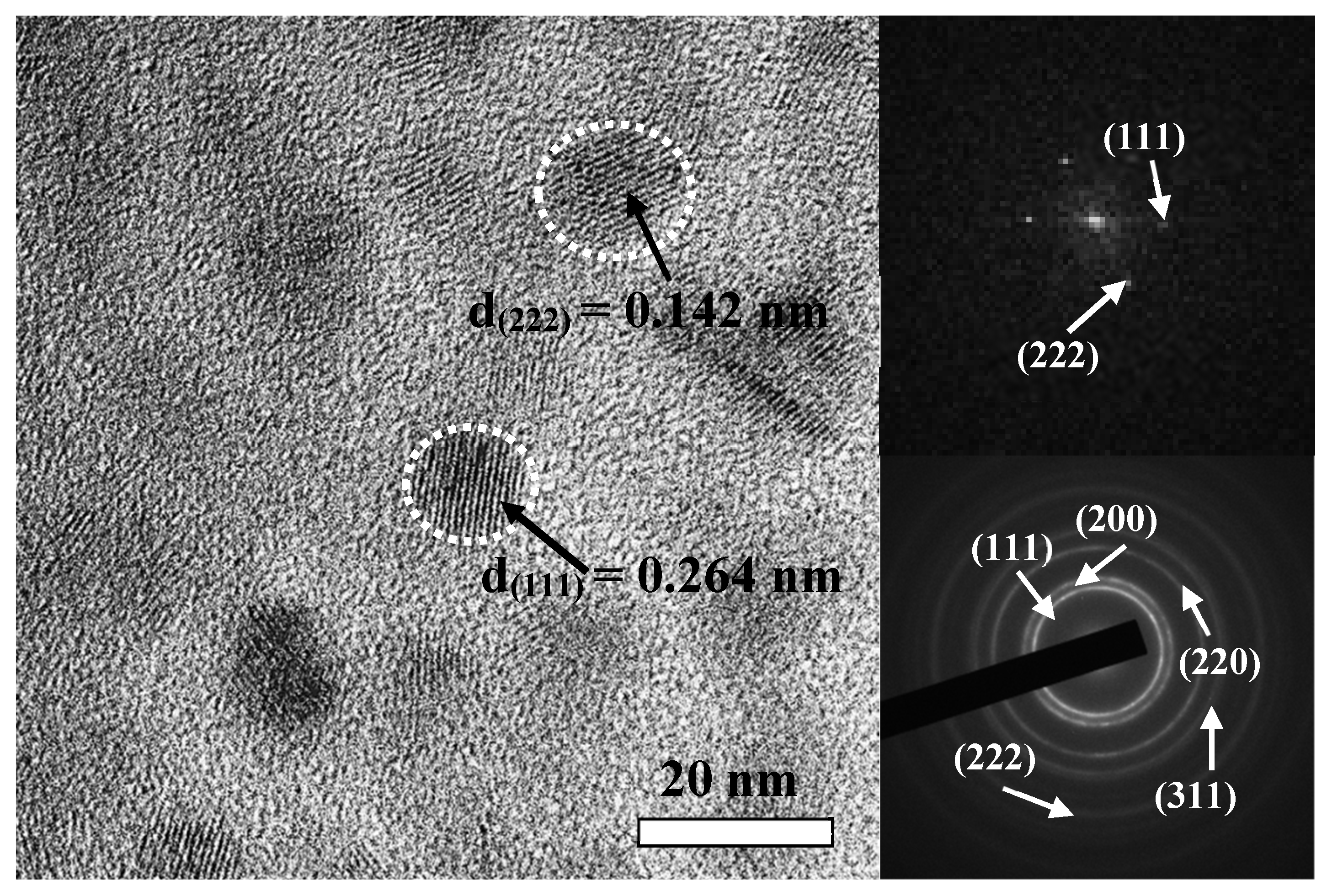
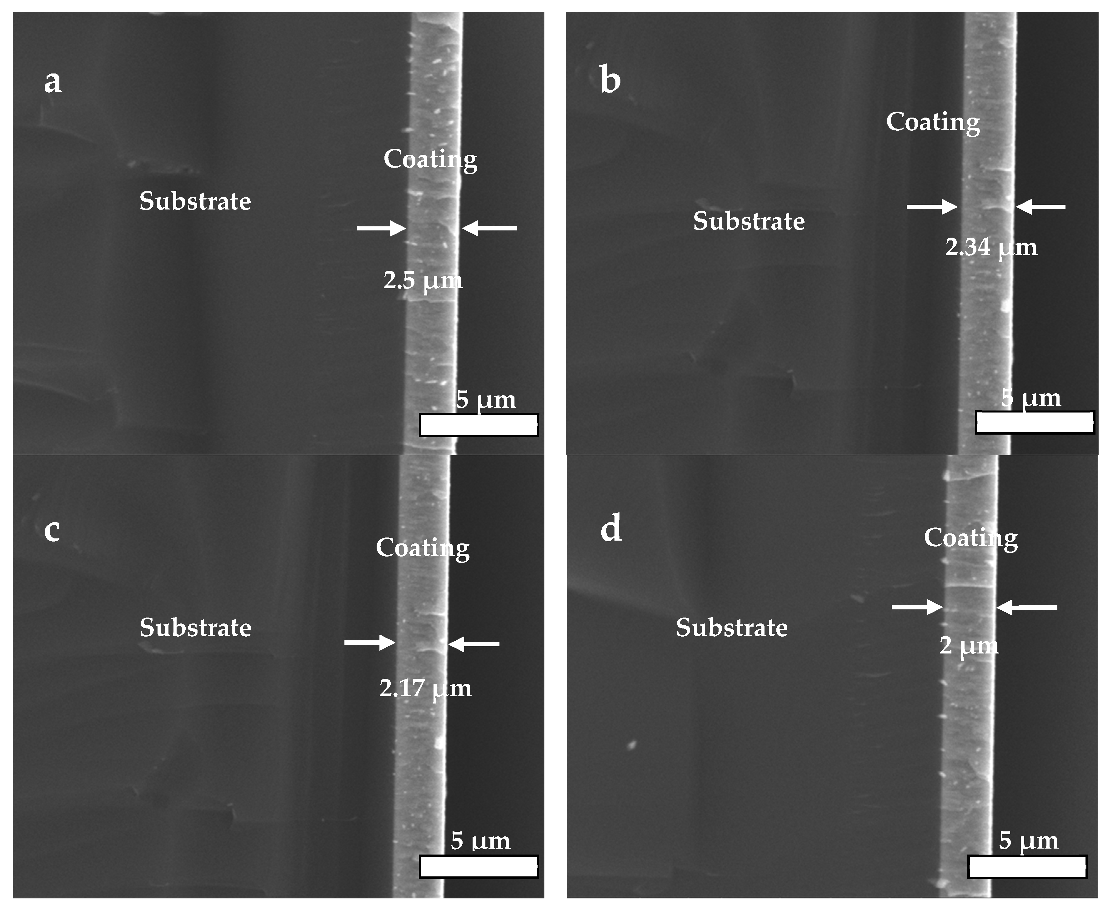
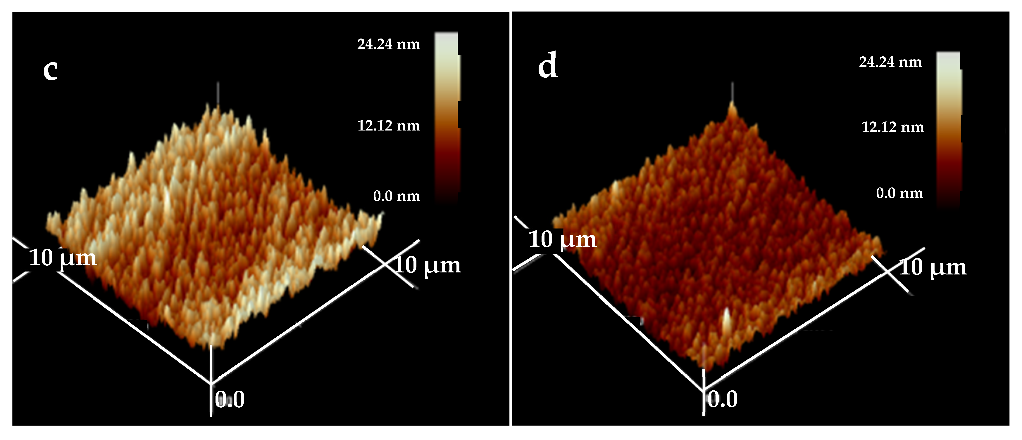
3.1. XRD, XPS, TEM, and AFM Analysis

The X-ray diffraction patterns for HfC coatings are shown in Figure 1. Figure 1 shows a sequence in 2θ diffraction lines for a face-centered cubic structure (FCC), NaCl type with a spatial group Fm3m. The coatings’ diffraction lines were in agreement with the international indexing files JCPDF 03-065-0975, which indicated the formation of the HfC phase. Moreover, according to JCPDF 01-071-4649, the 316L base was marked as austenite (Figure 1). From the diffractograms analysis, it was established that for the HfC coatings, the width of the XRD diffraction peak narrowed with an increase in bias voltage, which indicated that the coating’s crystallite size increased from about 7.5 to 14 nm as the bias voltage increased from −100 to −200 V. The growth of grain is related to the atom diffusion mechanism, in which increasing bias voltage increases the ion energies of arriving at the substrate, resulting in increasing adatom mobility, while atoms’ migration to the grain boundaries results in an increase in the grain size [31]. For the HfC coatings prepared at −150 and −200 V, the most intense peaks were found in the (111) orientation, which was consistent with the XRD pole figures of the (111) crystal plane (Figure 2). As shown in Figure 2a,b, a mostly scattered texture distribution could be observed, while it transformed to the (111) fiber texture when the bias voltage increased from −100 to −150 V. As shown in Figure 2d, the (111) fiber orientation became more pronounced and the highest intensity points were distributed at the pole figure center when the bias voltage was −200 V. During HfC coating with FCC structure growth, the formation of the (111) fiber texture was related to a competition mechanism between surface energy and strain energy. When the bias voltage was −150 and −200 V, the growth of the coating was dominated by strain energy. Its minimization drove grains to grow with (111) planes parallel to the coating surface in order to obtain the lowest strain energy. As a result, diffraction intensities of the HfC (111) orientation were obviously enhanced with the bias voltage increasing to more than −100 V.
The Hf4f and C1s spectra for the HfC coating deposited at a bias voltage of −200 V are presented in Figure 3a,b. The peak assignment was mainly performed according to [32,33]. The Hf4f peaks at binding energies of 14.3 and 16.65 eV were associated with Hf–C bonds, and the binding energy of 15.68 eV was associated with Hf–O bonds. It can be seen from Figure 3b that the C1s peaks at binding energies of 282.6 and 280.3 eV were attributed to C–C bonds and C–Hf bonds, respectively.
The HRTEM image of the HfC coating prepared at −200 V is presented in Figure 4. In the HRTEM image, nanospherical crystallites were embedded and their size was about 12–14 nm, which was consistent with the XRD results. Moreover, the coating’s (111) crystal plane (d = 0.264 nm) and (222) crystal plane (d = 0.142 nm) were always noticed, and their fast Fourier transform (FFT) spectrum and selected-area electron diffraction pattern including the (111), (200), (220), (311), and (222) planes marked are also shown in Figure 4.
The cross-sectional SEM images (Figure 5) illustrated that the coatings were integrated, dense and even in thickness. It could be observed that the bias voltage applied on the substrate had a big impact on the coatings’ deposition speed, and it gradually dropped from about 16.7 nm/min (2.5 μm/150 min) to 13.3 nm/min (2.0 μm/150 min), resulting in a decrease in thickness from 2.5 to 2 μm when the bias voltage changed from 0 to −200 V. This was due to enhanced flux of ions impinging on the growing HfC coating, resulting in the occurrence of re-sputtering with the bias voltage rising [34].
The surface morphologies of the HfC coatings are presented in Figure 6. The examined area is 10 × 10 μm2, and the test results of three-dimensional images were obtained. From these images, the surface roughness (RMS) for each coating was obtained, and the values were 11.96, 10.41, 5.593, and 5.591 nm at a bias voltage of 0, −100, −150, and −200 V, respectively. Obviously, the bias voltage had a huge impact on the coatings’ RMS; there was no obvious change as the bias voltage increased from 0 to −100 V, while a great decrease in roughness occurred with the bias voltage increasing to −150 V, which was due to the bombardment of high-energy ion strengthening the adatoms’ mobility, and they moved or diffused into the grain voids, generating smoother and denser coatings [35].

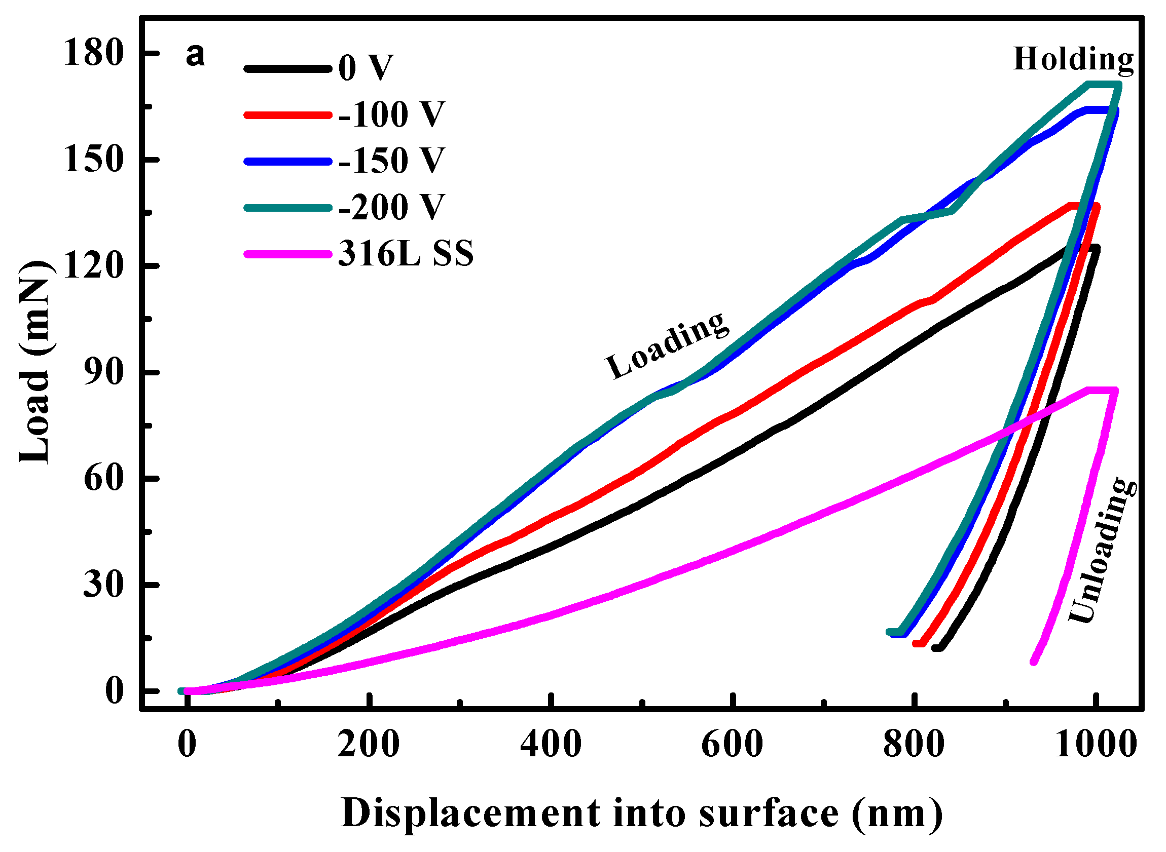
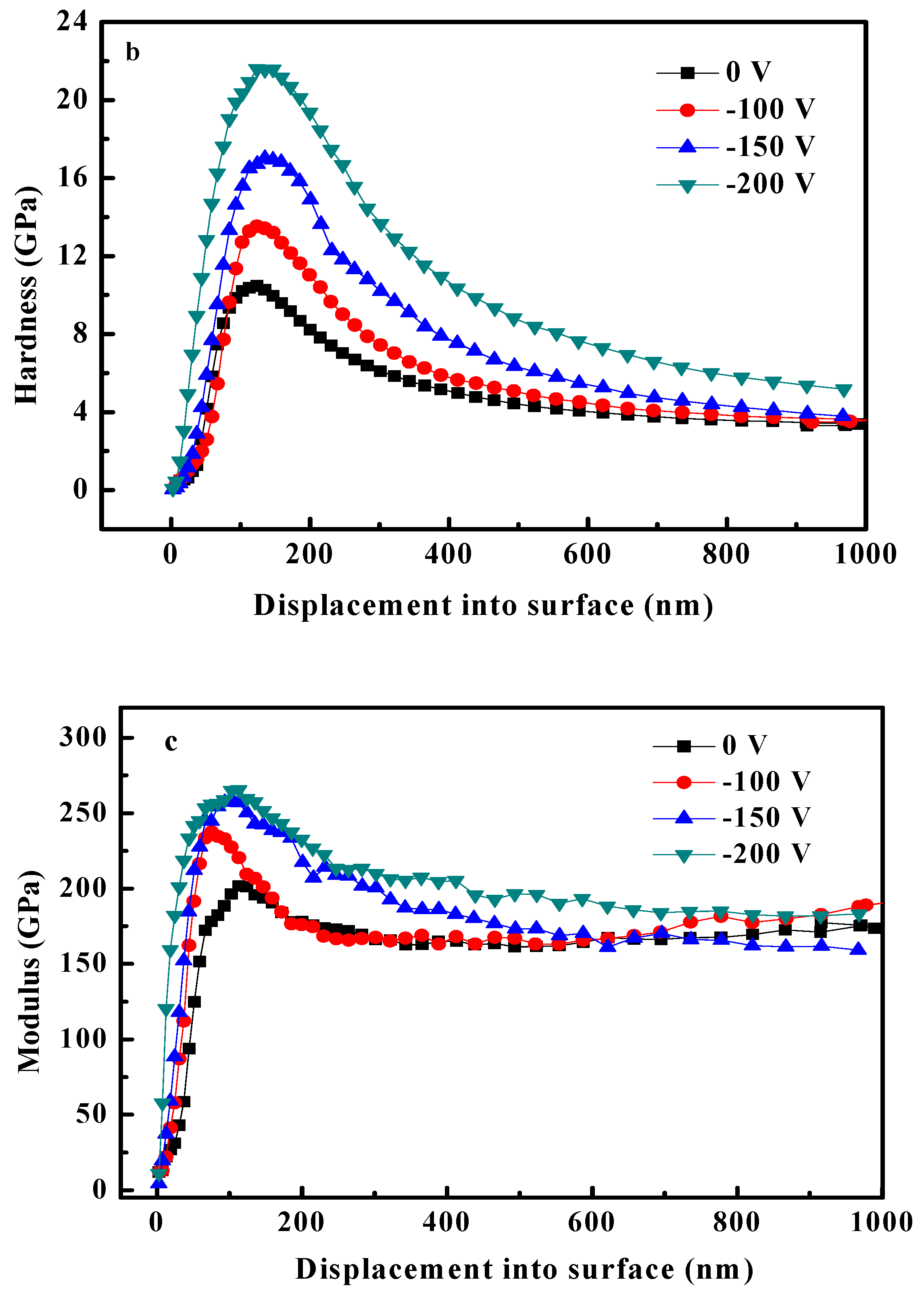
3.2. Mechanical Properties

The mechanical properties, such as hardness (H) and elastic modulus (E), of the HfC coatings deposited on 316L substrates were analyzed after establishing structural and morphological characteristics. Figure 7 shows the typical load–displacement curves of the coatings by using a Berkovich-type indenter, and H and E were determined by using the Oliver–Pharr method. In Figure 7a, the coatings’ elastic recovery ability was better compared to uncoated 316L after unloading. Moreover, the coatings’ toughness improved by increasing the bias voltage. The correlation of the coatings’ H, E, and indentation depth is shown in Figure 7b,c. Obviously, the soft 316L base affected greatly the coatings’ H and E when the indentation depth increased. In addition, the coatings’ H increased from 10.46 to 21.56 GPa, and their E also increased from 201.46 to 265.24 GPa with the bias voltage increasing from 0 to −200 V. The H difference of the coatings was due to the different crystallographic directions. With X-ray diffraction analysis (XRD), it was possible to determine that the coatings showed a preferential (111) orientation as the bias voltage increased. In general, the (111) orientation presented the highest hardness. Moreover, ions with higher energy bombarded the growing coating and drove the adatoms to diffuse completely as the bias voltage rose, forming a HfC coating with a denser structure, which is also attributed to an increase in the coating’s H.
The friction coefficient (COF) values are presented in Table 1. It could be noted that the coated 316L substrate’s COF was lower than that of bare 316L. The coatings’ COF values were 0.23, 0.20, 0.19, and 0.14. The coating deposited at 0 V exhibited the highest COF, and with increasing bias voltage, the COF started to decrease. It was reported in the literature [36,37] that the COF value correlates with mainly H/E ratios, and the higher value of H/E or H3/E2 represents the coating’s stronger resistance to plastic deformation. A higher bias voltage resulted in an increase in H/E (Table 1), which decreased the value of the COF. Moreover, better compactness and lower roughness also contributed to a decrease in the coatings’ COF.
The critical load values (Lc) for the HfC coatings prepared at different bias voltages are listed in Table 1. An Lc increase was observed, and the coatings’ Lc values were 24.7, 29.8, 35.7, and 45.2 N when the bias voltage was 0, −100, −150, and −200 V, respectively. It could be concluded that the increasing bias voltage contributes to the improvement of Lc. Figure 8 shows scratch track micrographs for the HfC coatings, where it is possible to identify interfacial failure mechanisms. As seen from Figure 8a,b, surface track generation and the coating falling off due to critical loads were observed at 0 and −100 V. When the bias voltage increased to −150 V, a few minute cracks and a little coating debris could be observed. When the bias voltage increased to −200 V, no obvious cracks and debris could be seen, and the scratch tracks became cleaner and smoother, revealing good adhesion between the coating and the 316 L substrate, which was consistent with the coatings’ Lc results. The scratch test results could be explained by the adatoms’ mobility and solid–atom interactions on the coating’s surface. The higher bias voltage contributed to the formation of impinging ion particles with more energy in the coating, and atoms with poor adhesion in the coating could be sputtered out, which improved the adatoms’ migration. As a result, grains grew in good order along certain directions, and a dense coating with reducing defects formed in a state of near thermodynamic equilibrium.

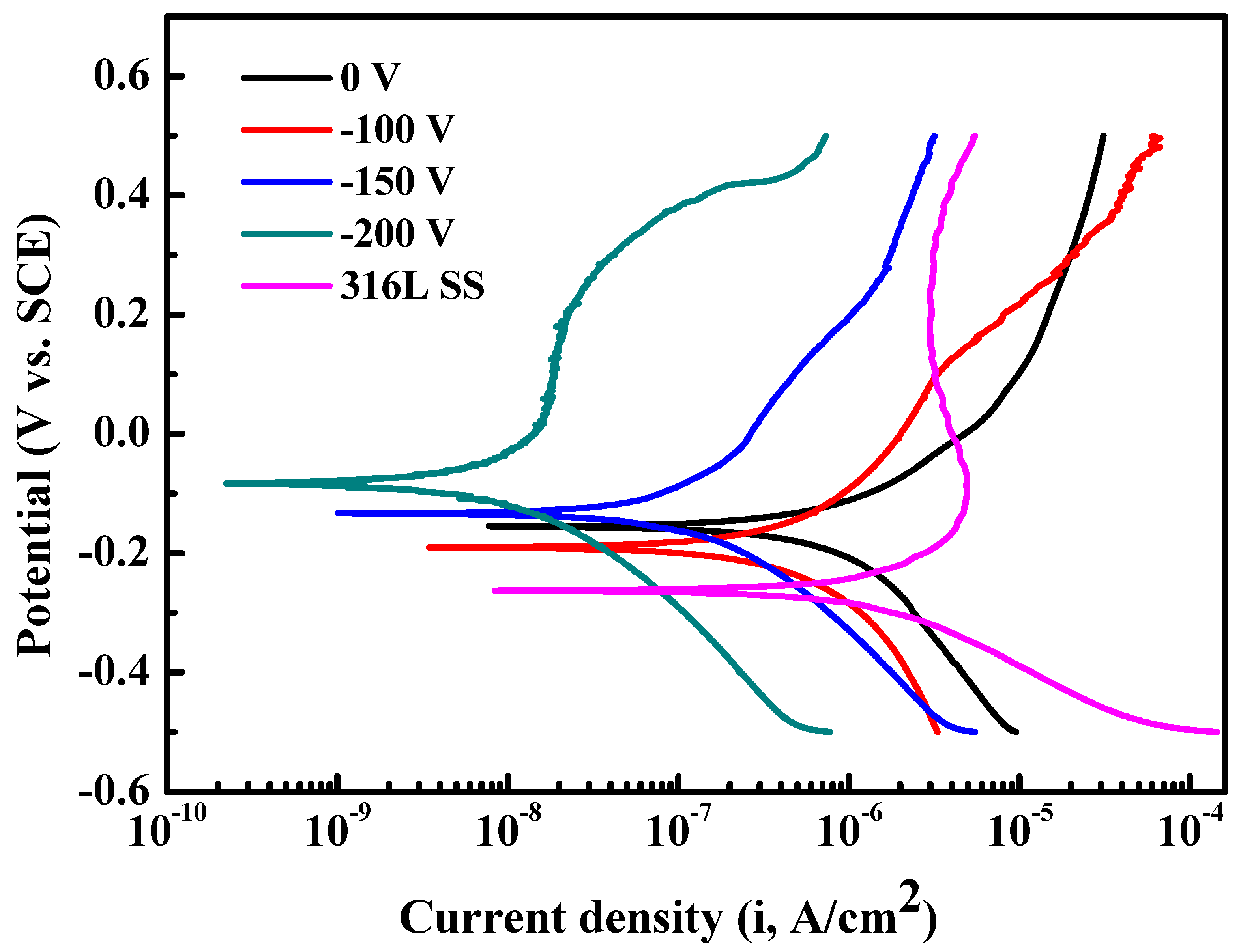
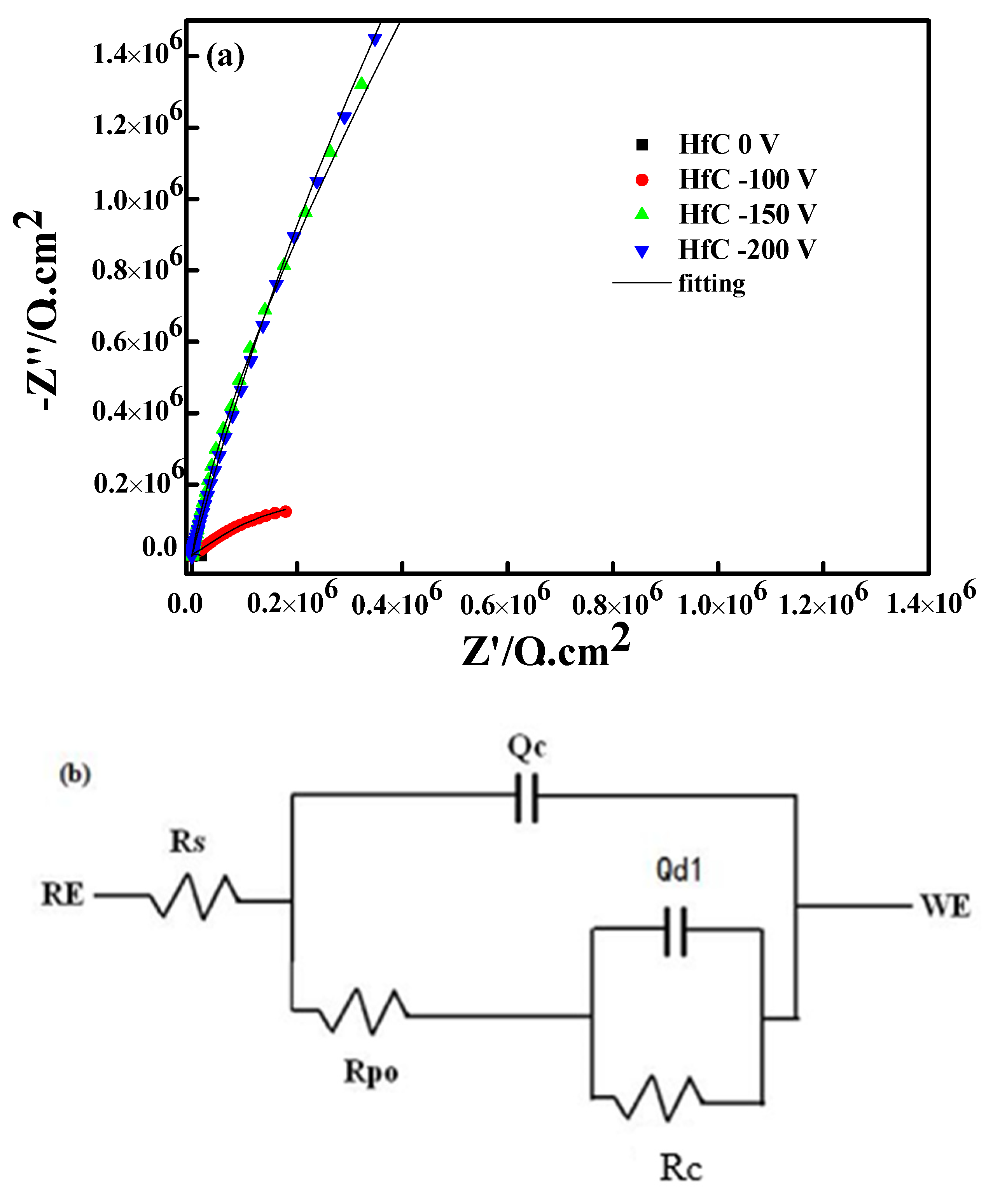
3.3. Corrosion Tests

The polarization curves are presented in Figure 9 for HfC coatings prepared at 0, −100, −150, and −200 V, and the coatings’ current density (Icoor) and corrosion potential (Ecoor) determined by the Tafel extrapolation method are listed in Table 2 [38,39]. For the 316L base, Icoor and Ecoor were about 4.19 × 10⁻⁶ A/cm2 and −202 mV, respectively. Compared to the 316L base, the decreasing of Icoor and an increase in Ecoor indicated the coating’s prevention on the 316L base from being corroded. Moreover, it is obvious that the coating’s anticorrosion property became increasingly better as the bias voltage increased, especially for the coating prepared at −200 V. Its Icorr was about 2.23 × 10⁻⁸ A/cm2, which decreased by two levels than that of the HfC coating deposited at 0 V. This indicates that the corrosion resistance of a coating deposited at −200 V is significantly superior to uncoated 316L SS and is the best one among the four coatings.
The change of the electrode–solution interface state was studied by electrochemical impedance spectroscopy (EIS), which was used to test the HfC coating’s corrosion resistance. Figure 10a displays the Nyquist diagrams of the HfC coatings prepared at 0, −100, −150, and −200 V, in which the increasing radius of Nyquist plots could be observed when the bias voltage increased from 0 to −200 V. Figure 10b shows the equivalent circuit, and the charge transfer resistance (RC) is listed in Table 2. It was obvious that the increasing bias voltage led to an increase in RC, implying the coating’s corrosion resistance was strengthened. The above test results could be explained by the fact that the coating had less roughness, better adhesion, and a denser structure at a higher bias voltage. First, the coating’s area exposed directly to PBS solution effectively reduced with its roughness decreasing, which contributed to improving its corrosion rate [40,41]. In addition, the denser HfC coating with few defects could block the valid path of PBS into the 316L base. Even if PBS solution contacted with the bonding interface between the coating and 316L, the better adhesion could preserve the coating [42,43].

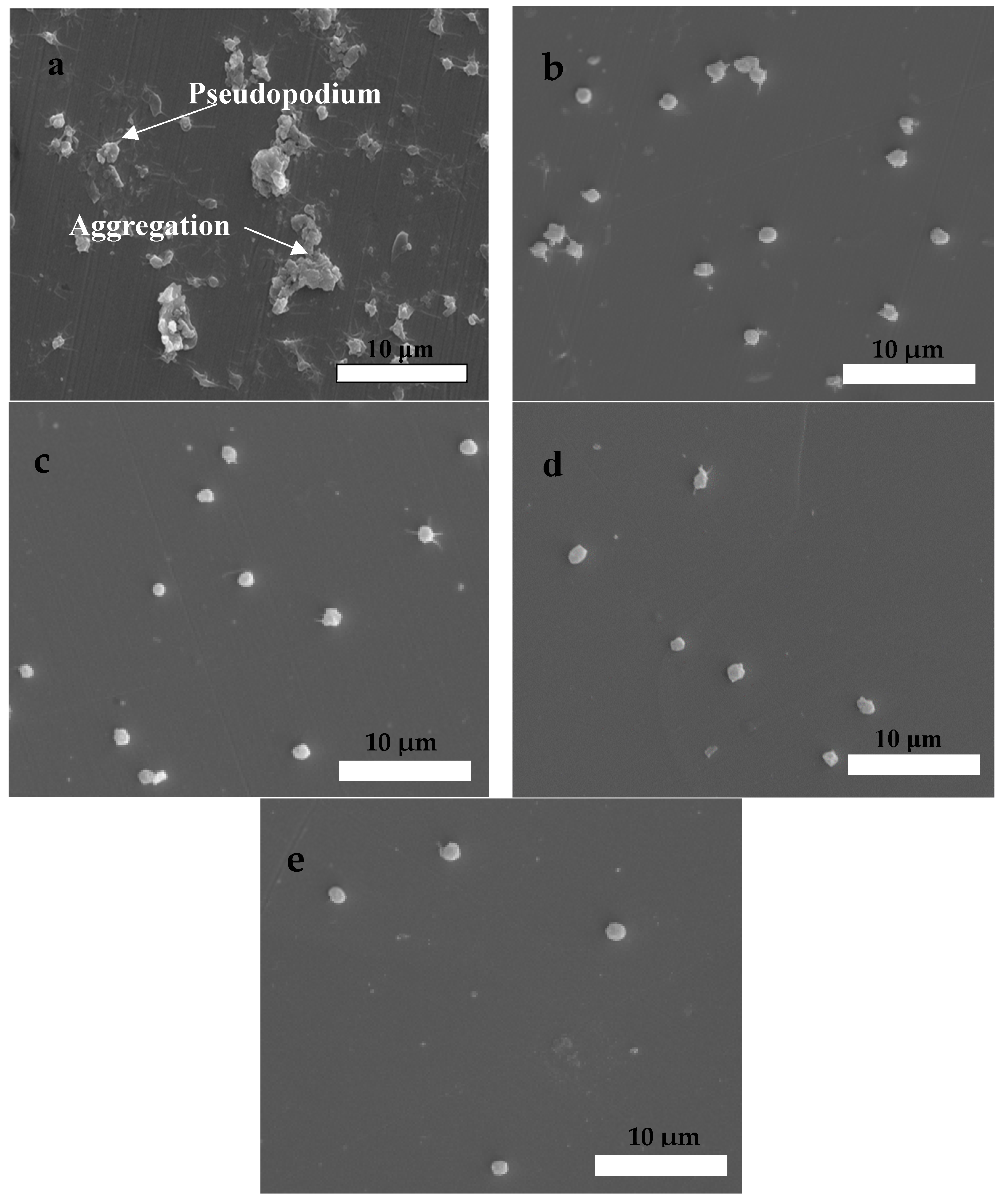
3.4. Blood Compatibility

Figure 11 shows the hemolysis ratio histogram of the HfC coatings prepared at 0, −100, −150, and −200 V. It was noted that the coatings’ hemolysis ratio was lower than that of the 316L base, and it decreased with the bias voltage increasing from 0 to −200 V for the HfC coatings.
Figure 12 demonstrates the platelet counts on the HfC-coated 316L and 316L substrates. The results showed that more platelets adhered to bare 316L compared to the coatings. For the HfC coating, the number of adhesion platelets decreased with the bias voltage increasing from 0 to −200 V, which revealed that the 316L base’s blood compatibility improves effectively by depositing an HfC coating and an increase in the bias voltage is in favor of improving the coating’s blood compatibility.
The platelets’ morphology was observed by SEM, and the captured images are displayed in Figure 13. In Figure 13a, the result revealed that many platelets adhered and aggregated slightly, and their anomalous pseudopodia extended on the surface of bare 316L. In Figure 13b–d, the different number and morphology features of platelets on the coatings could be observed as a function of bias voltage, evidencing a decrease in the number of adhesion platelets, and no anomalous pseudopodia could be seen when the bias voltage increased to −200 V. These results indicated that the coating’s blood compatibility greatly improved as the bias voltage increased. Based on the above results, on the one hand, the coatings’ blood compatibility was better than that of 316L, and on the other hand, it was significantly affected by the bias voltage. The coating with the rougher surface structure could capture platelets and result in their deformation [44,45]. Thus, the coating’s blood compatibility improved when the RMS decreased at a higher bias voltage. In addition, the surface energy [46] also affected the coating’s blood compatibility, and it could be improved as interfacial tension, dispersive energy, and γ S d / γ S p decreased [47,48,49]. As shown in Table 3, the coating’s interfacial tensions, dispersive energy, and γ S d / γ S p gradually decreased as the bias voltage increased, which resulted in the improvement of the HfC coating’s blood compatibility.

4. Conclusions

In this study, HfC coatings were prepared on a 316L substrate by an RF magnetron sputtering system. It was found that bias voltage has a strong effect on the coating’s microstructure, mechanical properties, corrosion resistance, and hemocompatibility. It was noted that the coatings’ deposition rate decreased progressively with increasing bias voltage due to re-sputtering. From the XRD and TEM results, it was established that for the HfC coatings, a strong (111) orientation was enhanced with a higher negative bias voltage (−150 and −200 V), and the grain size was about 10~14 nm at −200 V. The coating’s H, E, H/E, and H3/E2 exhibited a similar increasing trend, which was associated with enhanced ion bombardment when bias voltage increased. It was determined that the HfC coating prepared at −200 V had the lowest friction coefficient (0.14), which was due to its high mechanical properties (highest H/E) compared with other deposited HfC coatings. The highest Lc also belonged to the HfC coating prepared at −200 V, being 38.41 N. The HfC coating prepared at −200 V exhibited the best corrosion resistance, which was attributed to lower roughness, better adhesion, and a denser structure at a higher bias voltage. Hemocompatibility tests indicated that HfC coatings prepared at −150 and −200 V possessed better hemocompatibility compared with 316L and other two coatings prepared at 0 and −100 V. This could be explained by the fact that the coatings’ surface roughness and surface energy became lower when the bias voltage increased above −150 V. In conclusion, by controlling the bias voltage, the HfC coatings’ mechanical properties, corrosion resistance, and hemocompatibility can be improved, which opens up the possibility to apply this coating on 316L used in biomedical applications.

Author Contributions

Data curation, D.P., L.W., G.-Y.Z. and Z.-N.H.; Writing—original draft preparation, L.W. and M.-H.D.; Writing—review and editing, L.W. and M.-H.D.; Visualization, Z.-N.H., G.-Y.Z., J.-Y.Z. and Z.-R.F.; Supervision, D.P., J.-Y.Z. and Z.-R.F.; Project administration, M.-H.D.; Funding acquisition, L.W. All authors have read and agreed to the published version of the manuscript.

Funding

This work was funded by THE NINGXIA SCEINCE AND TECHNOLOGY KEY RESEARCH AND DEVELOPMENT PROJECT, grant number 2018BEE03029, THE NINGXIA NATURAL SCIENCE FOUNDATION, grant number 2019AAC03272, THE NINGXIA HIGHER SCHOOL SCIENTIFIC RESEARCH PROJECT, grant number NGY2018-250.

Institutional Review Board Statement

Not applicable.

Informed Consent Statement

Not applicable.

Data Availability Statement

The data presented in this study are available on request from the corresponding author.

Conflicts of Interest

The authors declare no conflict of interest.

References

  1. Cicha, I.; Singh, R.; Garlichs, C.D.; Alexiou, C. Nano-biomaterials for cardiovascular applications: Clinical perspective. J. Control. Release 2016, 229, 23–36. [Google Scholar] [CrossRef]
  2. Dobrowolska, A.; Kowalewski, P.; Ptak, A. Influence of the lubricating fluid on the changes on rubbing metallic biomaterials surface. Coll. Surf. A 2015, 480, 419–425. [Google Scholar] [CrossRef]
  3. Todai, M.; Nagase, T.; Hori, T.; Matsugaki, A.; Sekita, A.; Nakano, T. Novel TiNbZrMo high-entropy alloys for metallic biomaterials. Scr. Mater. 2017, 129, 65–68. [Google Scholar] [CrossRef] [Green Version]
  4. Ziętala, M.; Durejko, T.; Polański, M.; Kunce, I.; Płociński, T.; Zieliński, W.; Łazińska, M.; Stępniowski, W.; Czujko, T.; Kurzydłowski, K.J.; et al. The microstructure, mechanical properties and corrosion resistance of 316L stainless steel fabricated using laser engineered net shaping. Mater. Sci. Eng. A 2016, 677, 1–10. [Google Scholar] [CrossRef]
  5. Brooks, E.K.; Brooks, R.P.; Ehrensberger, M.T. Effects of simulated inflammation on the corrosion of 316L stainless steel. Mater. Sci. Eng. C 2017, 71, 200–205. [Google Scholar] [CrossRef]
  6. Chen, Y.; Wang, S.; Hao, Y.; Pu, J.; Jiang, X.; Huang, L.F.; Wang, L. Friction and wear behavior of CrN coating on 316L stainless steel in liquid sodium at elevated temperature. Tribol. Int. 2020, 143, 106079. [Google Scholar] [CrossRef]
  7. Amanov, A.; Lee, S.W.; Pyun, Y.S. Low friction and high strength of 316L stainless steel tubing for biomedical applications. Mater. Sci. Eng. C 2017, 71, 176–185. [Google Scholar] [CrossRef]
  8. Zhang, S.; Shi, R.; Chen, Y.; Wang, M. Corrosion behavior of oxide films on AISI 316L SS formed in high temperature water with simultaneous injection of zinc and aluminum. J. Alloys Compd. 2018, 731, 1230–1237. [Google Scholar] [CrossRef]
  9. Kaliaraj, G.S.; Vishwakarma, V.; Alagarsamy, K.; Kirubaharan, A.K. Biological and corrosion behavior of m-ZrO2 and t-ZrO2 coated 316L SS for potential biomedical applications. Ceram. Int. 2018, 44, 14940–14946. [Google Scholar] [CrossRef]
  10. Luo, H.; Su, H.; Dong, C.; Li, X. Passivation and electrochemical behavior of 316L stainless steel in chlorinated simulated concrete pore solution. Appl. Surf. Sci. 2017, 400, 38–48. [Google Scholar] [CrossRef]
  11. Huang, W.; Zalnezhad, E.; Musharavati, F.; Jahanshahi, P. Investigation of the tribological and biomechanical properties of CrAlTiN and CrN/NbN coatings on SST 304. Ceram. Int. 2017, 43, 7992–8003. [Google Scholar] [CrossRef]
  12. Qin, L.; Yi, H.; Kong, F.; Ma, H.; Guo, L.; Tian, L.; Tang, B. Effect of plasma molybdenized buffer layer on adhesive properties of TiN film coated on Ti6Al4V alloy. Appl. Surf. Sci. 2017, 403, 464–471. [Google Scholar] [CrossRef]
  13. Wu, Z.; Wu, Y.; Wang, Q. A comparative investigation on structure evolution of ZrN and CrN coatings against ion irradiation. Heliyon 2019, 5, e01370. [Google Scholar] [CrossRef] [PubMed] [Green Version]
  14. AlMangour, B.; Grzesiak, D.; Yang, J.M. In-situ formation of novel TiC-particle-reinforced 316L stainless steel bulk-form composites by selective laser melting. J. Alloys Compd. 2017, 706, 409–418. [Google Scholar] [CrossRef]
  15. Bait, L.; Azzouz, L.; Madaoui, N.; Saoula, N. Influence of substrate bias voltage on the properties of TiO2 deposited by radio-frequency magnetron sputtering on 304L for biomaterials applications. Appl. Surf. Sci. 2017, 395, 72–77. [Google Scholar] [CrossRef]
  16. Wang, R.; He, X.; Gao, Y.; Zhang, X.; Yao, X.; Tang, B. Antimicrobial property, cytocompatibility and corrosion resistance of Zn-doped ZrO2/TiO2 coatings on Ti6Al4V implants. Mater. Sci. Eng. C 2017, 75, 7–15. [Google Scholar] [CrossRef]
  17. Song, E.J.; Jo, H.; Kwon, S.H.; Ahn, J.H.; Kwon, J.D. Titanium oxynitride films for surface passivation of crystalline silicon deposited by plasma-enhanced atomic layer deposition to improve electrical conductivity. Thin Solid Film. 2020, 694, 137752. [Google Scholar] [CrossRef]
  18. Fernandez, D.A.R.; Brito, B.S.S.; Santos, I.A.D.; Soares, V.F.D.; Terto, A.R.; de Oliveira, G.B.; Hubler, R.; Batista, W.W.; Tentardini, E.K. Effect of hafnium contaminant present in zirconium targets on sputter deposited ZrN thin films. Nucl. Instrum. Methods B 2020, 462, 90–94. [Google Scholar] [CrossRef]
  19. Matsuno, H.; Yokoyama, A.; Watari, F.; Uo, M.; Kawasaki, T. Biocompatibility and osteogenesis of refractory metal implants, titanium, hafnium, niobium, tantalum and rhenium. Biomaterials 2001, 22, 1253–1262. [Google Scholar] [CrossRef]
  20. Sin, J.R.; Suñer, S.; Neville, A.; Emami, N. Fretting corrosion of hafnium in simulated body fluids. Tribol. Int. 2014, 75, 10–15. [Google Scholar]
  21. Pu, H.; Niu, Y.; Hu, C.; Wang, G.; Li, H.; Zeng, Y.; Zheng, X. Ablation of vacuum plasma sprayed TaC-based composite coatings. Ceram. Int. 2015, 41, 11387–11395. [Google Scholar] [CrossRef]
  22. Kumar, D.D.; Kumar, N.; Kalaiselvam, S.; Radhika, R.; Rabel, A.M.; Jayavel, R. Tribo-mechanical properties of reactive magnetron sputtered transition metal carbide coatings. Tribol. Int. 2017, 114, 234–244. [Google Scholar] [CrossRef]
  23. Sun, S.; Fu, H.; Ping, X.; Guo, X.; Lin, J.; Lei, Y.; Wu, W.; Zhou, J. Formation mechanism and mechanical properties of titanium-doped NbC reinforced Ni-based composite coatings. Appl. Surf. Sci. 2019, 476, 914–927. [Google Scholar] [CrossRef]
  24. Lasfargues, H.; Glechner, T.; Koller, C.M.; Paneta, V.; Primetzhofer, D.; Kolozsvári, S.; Holec, D.; Riedl, H.; Mayrhofer, P.H. Non-reactively sputtered ultra-high temperature Hf-C and Ta-C coatings. Surf. Coat. Technol. 2017, 309, 436–444. [Google Scholar] [CrossRef]
  25. Wang, Y.L.; Xiong, X.; Li, G.D.; Zhao, X.J.; Chen, Z.K.; Sun, W.; Wang, Z.S. Effect of gas composition on the microstructure and growth behavior of HfC coatings prepared by LPCVD. Solid State Sci. 2013, 20, 86–91. [Google Scholar] [CrossRef]
  26. Xiong, X.; Wang, Y.L.; Li, G.D.; Chen, Z.K.; Sun, W.; Wang, Z.S. HfC/ZrC ablation protective coating for carbon/carbon composites. Corros. Sci. 2013, 77, 25–30. [Google Scholar] [CrossRef]
  27. Braic, V.; Balaceanu, M.; Braic, M.; Vladescu, A.; Panseri, S.; Russo, A. Characterization of multi-principal-element (TiZrNbHfTa)N and (TiZrNbHfTa)C coatings for biomedical applications. J. Mech. Behav. Biomed. 2012, 10, 197–205. [Google Scholar] [CrossRef] [PubMed]
  28. Sharma, I.; Pattanayek, S.K. Effect of surface energy of solid surfaces on the micro- and macroscopic properties of adsorbed BSA and lysozyme. Biophys. Chem. 2017, 226, 14–22. [Google Scholar] [CrossRef] [PubMed]
  29. Zhao, J.; Chen, Y.; Yang, S.; Wu, S.; Zeng, R.; Wu, H.; Zhang, J.; Zha, Z.; Tu, M. Improving blood-compatibility via surface heparin-immobilization based on a liquid crystalline matrix. Mater. Sci. Eng. C 2016, 58, 133–141. [Google Scholar] [CrossRef] [PubMed]
  30. Zubair, M.; Rizwan, K.; Rashid, U.; Saeed, R.; Saeed, A.A.; Rasool, N.; Riaz, M. GC/MS profiling, in vitro antioxidant, antimicrobial and haemolytic activities of Smilax macrophylla leves. Arab. J. Chem. 2017, 10, 1460–1468. [Google Scholar] [CrossRef] [Green Version]
  31. Cai, X.; Gao, Y.; Cai, F.; Zhang, L.; Zhang, S. Effects of multi-layer structure on microstructure, wear and erosion performance of the Cr/CrN films on Ti alloy substrate. Appl. Surf. Sci. 2019, 483, 661–669. [Google Scholar] [CrossRef]
  32. Wang, Y.L.; Xiong, X.; Li, G.D.; Liu, H.F.; Chen, Z.K.; Sun, W.; Zhao, X.J. Preparation and ablation properties of Hf(Ta)C c0-deposition coating for carbon/carbon composites. Corros. Sci. 2013, 66, 177–182. [Google Scholar] [CrossRef]
  33. Ren, J.; Feng, E.; Zhang, Y.; Zhang, J.; Li, L. Microstructure and anti-ablation performance of HfC-TaC and HfC-ZrC coatings synthesized by CVD on C/C composites. Ceram. Inter. 2020, 46, 10147–10158. [Google Scholar] [CrossRef]
  34. Ding, J.C.; Wang, Q.M.; Liu, Z.R.; Jeong, S.; Zhang, T.F.; Kim, K.H. Influence of bias voltage on microstructure, mechanical and corrosion properties of AlSiN films deposited by HiPIMS technique. J. Alloys Compd. 2019, 772, 112–121. [Google Scholar] [CrossRef]
  35. Staszuk, M.; Pakuła, D.; Chladek, G.; Pawlyta, M.; Pancielejko, M.; Czaja, P. Investigation of the structure and properties of PVD coatings and ALD+PVD hybrid coatings deposited on sialon tool ceramics. Vacuum 2018, 154, 272–284. [Google Scholar] [CrossRef]
  36. Viteri, V.S.; Barandika, G.; Peremarc, C.P.J. Development of Ti-C-N coatings with improved tribological behavior and antibacterial properties. J. Mech. Behav. Biomed. 2016, 55, 75–86. [Google Scholar] [CrossRef] [PubMed]
  37. Kwok, S.C.H.; Ha, P.C.T.; McKenzie, D.R.; Bilek, M.M.M.; Chu, P.K. Biocompatibility of calcium and phosphorous doped diamond-like films synthesized by plasma immersion ion implantation and deposition. Diam. Relat. Mater. 2006, 15, 893–897. [Google Scholar] [CrossRef]
  38. Zhang, P.; Liu, Z. Enhancing surface integrity and corrosion resistance of laser cladded Cr-Ni alloys by hard turning and low plasticity burnishing. Appl. Surf. Sci. 2017, 409, 169–178. [Google Scholar] [CrossRef]
  39. Wang, Q.Y.; Xi, Y.C.; Zhao, Y.H.; Liu, S.; Bai, S.L.; Liu, Z.D. Effects of laser re-melting and annealing on microstructure, mechanical property and corrosion resistance of Fe-based amorphous/crystalline composite coating. Mater. Charact. 2017, 127, 239–247. [Google Scholar] [CrossRef]
  40. Azar, G.T.P.; Er, D.; Ürgen, M. The role of superimposing pulse bias voltage on DC bias on the macroparticle attachment and structure of TiAlN coatings produced with CA-PVD. Surf. Coat. Technol. 2018, 350, 1050–1057. [Google Scholar] [CrossRef]
  41. Katta, P.P.; Nalliyan, R. Corrosion resistance with self-healing behavior and biocompatibility of Ce incorporated niobium oxide coated 316L SS for orthopedic applications. Surf. Coat. Technol. 2019, 375, 715–726. [Google Scholar] [CrossRef]
  42. Han, G.; Lu, Z.; Ru, X.; Chen, J.; Zhang, J.; Shoji, T. Properties of oxide films formed on 316L SS and model alloys with modified Ni, Cr and Si contents in high temperature water. Corros. Sci. 2016, 106, 157–171. [Google Scholar] [CrossRef]
  43. Mohan, L.; Anandan, C.; Rajendran, N. Electrochemical behavior and effect of heat treatment on morphology, crystalline structure of self-organized TiO2 nanotube arrays on Ti-6Al-7Nb for biomedical applications. Mater. Sci. Eng. C 2015, 50, 394–401. [Google Scholar] [CrossRef] [PubMed]
  44. Garcia-Lobato, M.A.; Mtz-Enriquez, A.I.; Garcia, C.R.; Velazquez-Manzanares, M.; Avalos-Belmontes, F.; Ramos-Gonzalez, R.; Garcia-Cerda, L.A. Corrosion resistance and in vitro bioactivity of dense and porous titania coatings deposited on 316L SS by spraying method. Appl. Surf. Sci. 2019, 484, 975–980. [Google Scholar] [CrossRef]
  45. Kumar, D.D.; Kaliaraj, G.S. Multifunctional zirconium nitride/copper multilayer coatings on medical grade 316L SS and titanium substrates for biomedical applications. J. Mech. Behav. Biomed. 2018, 77, 106–115. [Google Scholar] [CrossRef]
  46. Zhao, M.L.; Li, D.J.; Guo, M.X.; Zhang, Y.T.; Gu, H.Q.; Deng, X.Y.; Wan, R.X.; Sun, X. The different N concentrations induced cytocompatibility and hemocompatibility of MWCNTs with CNx coatings. Surf. Coat. Technol. 2013, 229, 90–96. [Google Scholar] [CrossRef]
  47. Huang, Z.; Luo, P.; Chen, W.; Pan, S.; Chen, D. Hemocompatibility of ZnO thin films prepared by filtered cathodic vacuum arc deposition. Vacuum 2013, 89, 220–224. [Google Scholar] [CrossRef]
  48. Amin, M.S.; Randeniya, L.K.; Bendavid, A.; Martin, P.J.; Preston, E.W. Biomimetic apatite growth from simulated body fluid on various oxide containing DLC thin films. Diam. Relat. Mater. 2012, 21, 42–49. [Google Scholar] [CrossRef]
  49. Kwok, S.C.H.; Zhang, W.; Wan, G.J.; McKenzie, D.R.; Bilek, M.M.M.; Chu, P.K. Hemocompatibility and anti-bacterial properties of silver doped diamond-like carbon prepared by pulsed filtered cathodic vacuum arc deposition. Diam. Relat. Mater. 2007, 16, 1353–1360. [Google Scholar] [CrossRef]
Figure 1. XRD patterns of 316L SS and HfC coatings deposited at different bias voltages.
Coatings 11 00963 g001
Figure 2. Pole figures of HfC coatings deposited at different bias voltages: (a) 0 V, (b) −100 V, (c) −150 V, and (d) −200 V.
Coatings 11 00963 g002
Figure 3. XPS spectra of HfC coating deposited at a bias voltage of −200 V: (a) Hf4f and (b) C1s.
Coatings 11 00963 g003aCoatings 11 00963 g003b
Figure 4. HRTEM image and SAED pattern of HfC coating deposited at a bias voltage of −200 V.
Coatings 11 00963 g004
Figure 5. Cross-sectional SEM images of HfC coatings deposited at different bias voltages: (a) 0 V, (b) −100 V, (c) −150 V, and (d) −200 V.
Coatings 11 00963 g005
Figure 6. AFM topography images of HfC coatings deposited at different bias voltages: (a) 0 V, (b) −100 V, (c) −150 V, and (d) −200 V.
Coatings 11 00963 g006aCoatings 11 00963 g006b
Figure 7. Nanoindentation load–displacement curves (a), hardness–displacement curves (b), and Young’s modulus–displacement curves (c) of uncoated 316L SS and 316L SS with HfC coatings deposited at different bias voltages.
Coatings 11 00963 g007aCoatings 11 00963 g007b
Figure 8. Typical scratch track images of HfC coatings deposited at different bias voltages: (a) 0 V, (b) −100 V, (c) −150 V, and (d) −200 V.
Coatings 11 00963 g008
Figure 9. Potentiodynamic polarization curves of 316L SS and HfC coatings deposited at different bias voltages: (a) 0 V, (b) −100 V, (c) −150 V, (d) −200 V, and (e) AISI 316L.
Coatings 11 00963 g009
Figure 10. EIS of HfC coatings deposited at different bias voltages. (a) Nyquist curve and (b) equivalent electrical circuit model.
Coatings 11 00963 g010
Figure 11. Hemolysis ratio results of the uncoated 316L SS and HfC coatings deposited at different bias voltages: (a) 316L SS, (b) 0 V, (c) −100 V, (d) −150 V, and (e) −200 V.
Coatings 11 00963 g011
Figure 12. Statistical analysis of the adhered platelet number on the substrate of the uncoated 316L SS and HfC coatings deposited at different bias voltages. (a) 316L SS, (b) 0 V, (c) −100 V, (d) −150 V, and (e) −200 V.
Coatings 11 00963 g012
Figure 13. SEM morphologies of platelets adhered on the surface of the uncoated 316L SS and HfC coatings deposited at different bias voltages: (a) 316L SS, (b) 0 V, (c) −100 V, (d) −150 V, and (e) −200 V.
Coatings 11 00963 g013
Table 1. Mechanical characteristics, critical load, and friction coefficient of HfC coatings deposited at different bias voltages.
SampleHardness (GPa)Modulus (GPa)H/EH3/E2 (GPa)Lc (N)μ
316L SS6.1 ± 0.1192.1 ± 1.10.030.006-0.44
HfC coating (0 V)10.46 ± 0.2201.46 ± 2.30.050.02824.7 ± 0.90.23
HfC coating (−100 V)13.52 ± 0.4237.95 ± 3.90.050.04429.8 ± 0.70.20
HfC coating (−150 V)17.03 ± 0.6259.33 ± 1.80.060.07335.7 ± 1.30.19
HfC coating (−200 V)21.56 ± 0.3265.24 ± 1.40.080.14345.2 ± 1.10.14
Table 2. Corrosion parameters in PBS solution for HfC coatings deposited at different bias voltages.
SampleIcorr (A/cm2)Ecorr (mV)Rc (Ω)
316L SS 4.19 × 10⁻⁶−202-
HfC coating (0 V)1.79 × 10⁻⁶−1561.63 × 104
HfC coating (−100 V)7.62 × 10⁻⁷−1916.12 × 105
HfC coating (−150 V)1.47 × 10⁻⁷−1347.28 × 106
HfC coating (−200 V)2.23 × 10⁻⁸−82.53.84 × 107
Table 3. Contact angle, surface energy of the HfC coatings, and interfacial tensions with water and glycol.
SamplesContact Angle (°)Surface Energy Components (mN/m)Interfacial Tensions
WaterGlycol γ S d γ S p γ S d / γ S p γ S W
316L SS 83.259.120.97.42.819.6
HfC coating (0 V)10072.117.935.933.5
HfC coating (−100 V)89.368.118.18.22.225.4
HfC coating (−150 V)86.264.419.811.71.725.2
HfC coating (−200 V)84.762.118.811.21.624.8
Publisher’s Note: MDPI stays neutral with regard to jurisdictional claims in published maps and institutional affiliations.

