Article

Molecular Dynamics Study on Nano-Friction and Wear Mechanism of Nickel-Based Polycrystalline Superalloy Coating

1
School of Mechanical and Electronical Engineering, Lanzhou University of Technology, Lanzhou 730050, China
2
State Key Laboratory of Solid Lubrication, Lanzhou Institute of Chemical Physics, Chinese Academy of Sciences, Lanzhou 730000, China
*
Authors to whom correspondence should be addressed.
Coatings 2021, 11(8), 896; https://doi.org/10.3390/coatings11080896
Submission received: 21 June 2021 / Revised: 15 July 2021 / Accepted: 19 July 2021 / Published: 26 July 2021
(This article belongs to the Special Issue Anti-wear Coatings for High Temperature Applications)

Abstract

:
In this work, molecular dynamics simulations are employed to study the nanotribological process of nickel-based polycrystalline superalloy coating. A series of simulations were carried out using the method of repeated friction to explore the influence of frictional force, friction coefficient, grinding groove morphology, wear scar depth, debris flow direction, subsurface damage degree and evolution of defects during the nano-friction process. In addition, the change mechanism of different grain sizes on wear scar depth, frictional force, friction coefficient, and internal damage in the repeated friction process is also explored. The results show that the frictional force is related to the direction of the dislocation slip, and that the friction coefficient change is related to the number of repeated frictions. Moreover, it is observed that the grinding ball has a shunting effect on the formed wear debris atoms, and the shunt point is located at the maximum horizontal radius. We reveal that the grain boundary structure has a strengthening effect. When the grinding ball rubs to the grain boundary, the nucleation of dislocation defects inside the workpiece is obviously hindered by it. Simultaneously, we also find that the closer the subsurface is to the bottom of the grinding ball, the greater the degree of damage to the workpiece by friction. Furthermore, with the grain size decreases that the material begins to soften, resulting in a decrease of frictional force, friction coefficient, and smaller defects are formed inside the workpiece. The research of this work can better clarify the microscopic mechanism of the polycrystalline friction process.

1. Introduction

Nickel-based superalloy coating has been widely used in various aeronautical, aerospace engines and gas turbines due to its superior creep resistance, high temperature resistance, oxidation resistance, good thermal stability and thermal fatigue resistance [1,2,3,4]. The process of nickel-based alloy coating mainly includes oxygen-acetylene flame remelting, intermediate frequency induction remelting and plasma surfacing. However, nickel alloy coating used in aero-engine blades and gas turbine blades has long been served in high temperature and high load working environment [5,6]. Generally, nickel alloy turbine blades are prone to fretting fatigue failure due to bad working conditions [7]. Previous studies have shown that fretting fatigue failure is caused by the combined action of multiple wear of the contact surface and reciprocating alternating stress [8]. The wear of the contact surface will damage the inside of the material and form damage wear marks, thereby promoting the formation of fretting fatigue cracks [9,10]. Therefore, the study of friction and wear of nickel-based alloy coating is of great significance to accurately predict the fretting fatigue life of turbine blades. For a long time, the research on friction and wear of contact surface is mostly carried out through experiments. In addition, because the scale of cracks and wear marks in actual friction is only a few nanometers or smaller. It is difficult to observe dynamically through experiments [11,12]. In this context, the above process is realized by molecular dynamic (MD) simulation. It has become an effective tool for studying material removal, surface formation and microstructure evolution in nano-friction. It is particularly significant to study the repeated friction of materials, the formation mechanism of wear chips and the generation process of internal dislocations in the friction process [13,14].
Over the past few decades, many researchers have successfully used MD simulations to study ultra-precise nanomachining and nanomachining processes. Among them, Fang et al. [15] performed the effects of different processing parameters on subsurface damage and material removal of nickel/copper multilayers. Yin et al. [16] conducted the MD simulation study on nano-wear of SiC/Al nanocomposites. Xu et al. [17] carried out an MD study on nano-grinding of monocrystalline silicon substrates, and analyzed the effects of grinding depth, speed and copper thickness on material removal, defects, grinding force and temperature. Wang et al. [18] applied MD simulation to study the nano-friction of single crystal gallium nitride (GaN). Xiao et al. [19] studied the material removal mechanism and surface formation of single crystal copper dynamic ploughing, by combining MD simulation and experimental experiments. Xu et al. [20] studied the effects of rebound and side flow on surface formation, hysteresis, and phase transition during nano cutting of monocrystalline silicon. Fang et al. [21] studied the subsurface damage and material removal mechanism of single crystal copper in nanoscale high-speed grinding with a diamond tip. Ren et al. [22] observed the ultra high-speed grinding characteristics of single crystal nickel. However, for the nano-friction of polycrystalline nickel-based alloys, especially the repeated friction on the surface of the workpiece, the research on the microscopic mechanism of materials is still under explored. Because the actual friction and wear is a process that is repeated many times, and is different from machining, it is very important to study the repeated friction of polycrystalline nickel. In this paper, MD is used to carry out repeated friction of the tool in all directions of the workpiece under a constant load by analyzing the flow direction of the wear debris of the nickel-based alloy under different parameters, and the reason for the surface hardening caused by repeated friction.

2. Friction Modeling and Simulation Process

The high temperature dry sliding wear test is carried out by using ball disc friction meter. The ball and disc are made of Diamond and K465 polycrystalline superalloy, respectively, and the size of the ball and disc was 43 nm × 43 nm × 18 nm square nickel-base superalloy disk polished to average roughness Ra = 0.6 μm. Then ultrasonic cleaning was carried out with anhydrous ethanol. The disc sample is then dried for wear testing. High temperature friction meter HT-1000 is used for wear test, and the test diagram is shown in Figure 1. In this simulation, the constant load applied on the pressure bar is 85 nn, and the radius of the rotating disc is shown as R in the figure.
The simulation process is mainly based on the above friction principle. Figure 2 shows the molecular dynamics simulation model of nickel-based polycrystalline alloy, which is composed of polycrystalline nickel matrix and diamond grinding ball. The material of the workpiece is a Ni-Fe-Cr alloy model with FCC lattice structure. Its lattice constant is 0.352 nm. The content of Ni in the workpiece is 53%, Cr 18% and Fe 29%. The elements are randomly distributed. Diamond grinding balls are much harder than polycrystalline nickel substrates, and the wear of the grinding balls during the friction process is negligible. The radius of the grinding ball is 3.0 nm, and the initial position is 1 nm above the surface of the workpiece. Specific simulation parameters are shown in Table 1. The model is still in the simulation test and has not been tested in practice.
In addition, the workpiece is divided into boundary layer, temperature layer and Newton layer [17]. The boundary layer is fixed as the base layer of the workpiece. The temperature layer keeps the temperature of the entire system constant during the friction process, making the temperature of the system close to the actual. The atoms in the Newtonian layer adjacent to the constant temperature atoms are the focus of this study, the motions of these atoms follow Newton’s second law of motion. The model size in the simulation is built large enough to eliminate the boundary effect [23].
Potential function is the key factor in MD simulation. In this paper, the EAM potential function, Tersoff potential function and Morse potential function are used to describe the friction process of the whole model. The EAM potential is applied between metals and alloys. It is used to be the potential function of Ni-Fe-Cr alloy [24]. EAM potential function is a multi-body potential function. The total potential is expressed as follows:
E t = i F i ( ρ i ) + 1 2 i j ϕ i j ( r i j )
ρ i = i j ρ i j ( r i j )
where φij is the interaction potential between atoms i and j. Fi (ρi) represents the embedded energy induced by the embedding of atoms, and ρij is the electron density at the position of atoms.
Morse potential is used to represent the interaction between workpiece and tool atoms. The Morse potential function is a classic dual potential function based on the diatomic theory. It is widely used because of its convenient calculation. The parameters of the main Morse potential function between some atoms used in this simulation are shown in Table 2 [3].
The Morse potential energy formula as follows [25].
V ( r i j ) = D e [ e 2 α ( r e r i j ) 2 e α ( r e r i j ) ]
where De is the binding energy between atoms, α is the elastic modulus of the material, rij is the instantaneous distance between atoms, and re is the equilibrium distance between atoms. In addition, the Tersoff potential function [26] is used in the simulation to describe the interaction between carbon atoms.

3. Results and Discussion

3.1. Frictional Force and Friction Coefficient

In the process of grinding the ball against the workpiece repeatedly, the forces in X, Y and Z directions are extracted, as shown in 
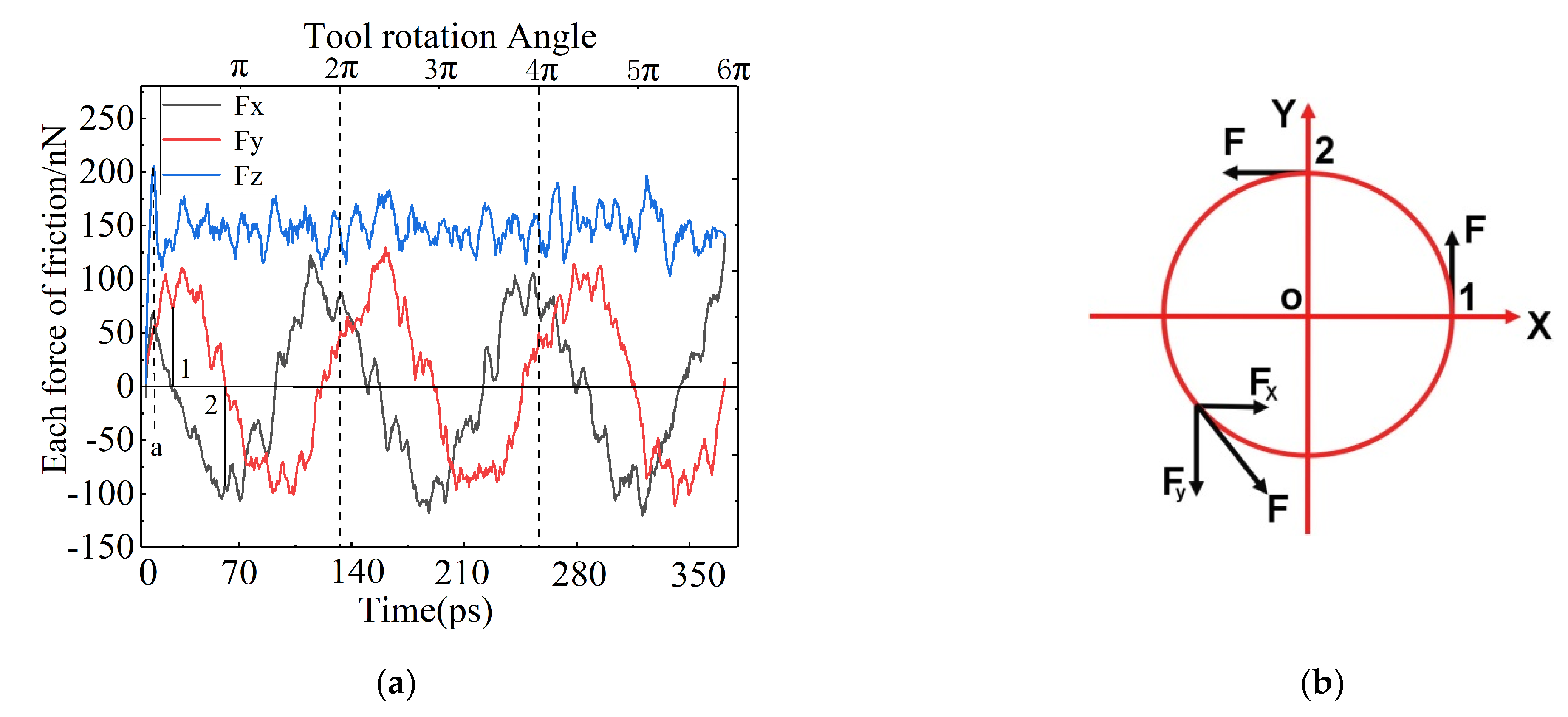
Figure 3a. The force in the Fz direction changes drastically at the initial stage of friction, and it rapidly increases to 200 nN at a in the figure. This is because the grinding ball begins to press down, and the workpiece is elastically deformed, causing the force in the Fz direction to continue to increase. Then it enters the stage of stable friction, the change tends to be smooth and fluctuates at 150 nN. In addition, the component force along the X and Y directions changes periodically, which the force value at the peak and trough is about 100 nN. This is because the friction of the grinding ball is repeated rotation, and the direction of rotation of the grinding ball changes with the time step, as shown in Figure 3b, causing the component force curve to fluctuate in a trigonometric function curve.
Theoretically, when the values of Fx or Fy are 0, the force in the other direction should be the maximum, as shown by points 1 and 2 in Figure 3b. However, at 1 and 2 points in Figure 3a, the values of Fy and Fx are not the maximum values. This is because the workpiece material is not uniform, resulting in the formation of the chip is not continuous. When the grinding ball rubs to position 2 (point 2 in Figure 3b). Because the formation of wear debris is discrete, as well as the grain boundaries and defect structures generated during the friction process, the formation of wear debris accumulation and dislocation defects at the grain boundaries hinder the grinding ball. Therefore, the Fy value at point 2 is not the maximum, but appear later.
In order to further explore the reasons for the influence of friction fluctuations, the component forces Fx and Fy (nN) in the two directions are combined. The total frictional force F (nN) is obtained by the formula:
F = ( F x ) 2 + ( F y ) 2
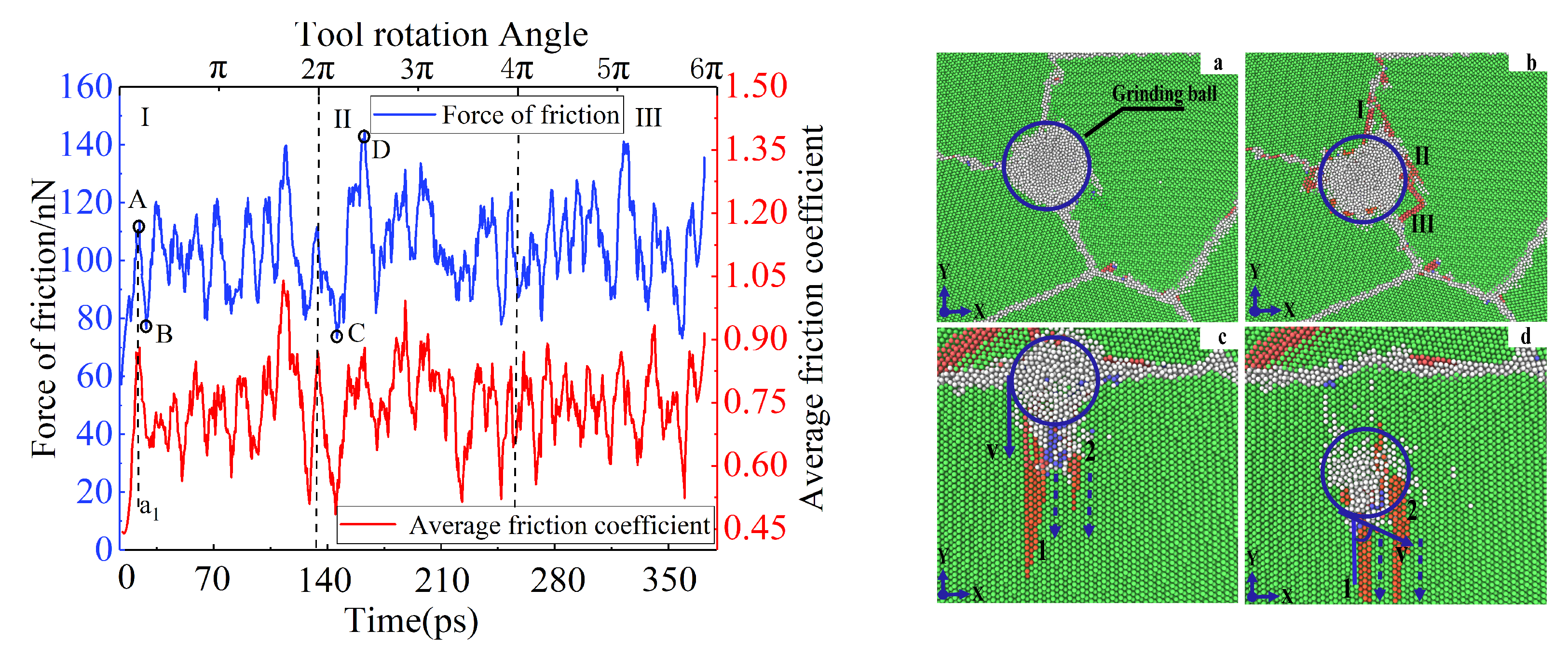
The changes of frictional force and friction coefficient with time step are shown in Figure 4, which are represented by blue and red curves, respectively. The curve changes in two stages with distinct characteristics (initial friction stage and stable friction stage). At the initial stage of friction, the frictional force rapidly increases to 110 nN at A point as shown in Figure 4. This is because the grinding ball is initially pressed down, and the workpiece is in the elastic deformation stage. At this time, there is no dislocation defect around the grinding ball, as shown in Figure 4a, which does not cause damage to the internal atoms of the workpiece, and so the frictional force is continuously increasing. After that, it enters the stage of stable friction, and the change tends to be gentle. The frictional force begins to gradually decrease to 75 nN at B point as shown in Figure 4. It can be seen that plastic deformation occurs inside the workpiece, and more defects are generated around the grinding ball. The defects are connected with each other around the grinding ball, forming a stable defect structure. The surface plastic deformation has occurred as shown in Figure 4b I, II and III. With the friction of the grinding ball, the friction value at C point in Figure 4 is smaller, because during the friction process, the dislocation slip direction (shown 1 and 2 at c in Figure 4) is consistent with the moving direction of the grinding ball. At this time, the defect has less hindrance to the movement of the grinding ball, so the frictional force is smaller. However, the frictional force at d point is relatively larger. Due to the dislocation slip direction (shown 1 and 2 at d in Figure 4) being almost perpendicular to the speed of the grinding ball, the resulting dislocation defects have a greater hindrance to the movement of the grinding ball. Thus, the frictional force becomes larger. Moreover, the friction coefficient is the ratio of the frictional force to the vertical component force. It can be observed from the figure that the friction coefficient of the first friction fluctuates greatly. During the second and third frictions, the amplitude of the curve fluctuates slightly, showing low amplitude and high frequency fluctuations. This is due to the fact that, in the process of first friction that the contact area between the grinding ball, the workpiece is larger, and the temperature generated by the friction is higher, resulting in a larger fluctuation in the amplitude of the friction coefficient. The next two frictions are repeated frictions, and the surface of the workpiece has been destroyed at this moment. Due to the high temperature hardening parts of the atoms on the surface, the contact area between the grinding ball and the workpiece is lesser, so the curve of friction coefficient fluctuates smoothly.

3.2. Debris Accumulation and Flow Direction

The study of wear debris formation and flow direction is also of great significance. 
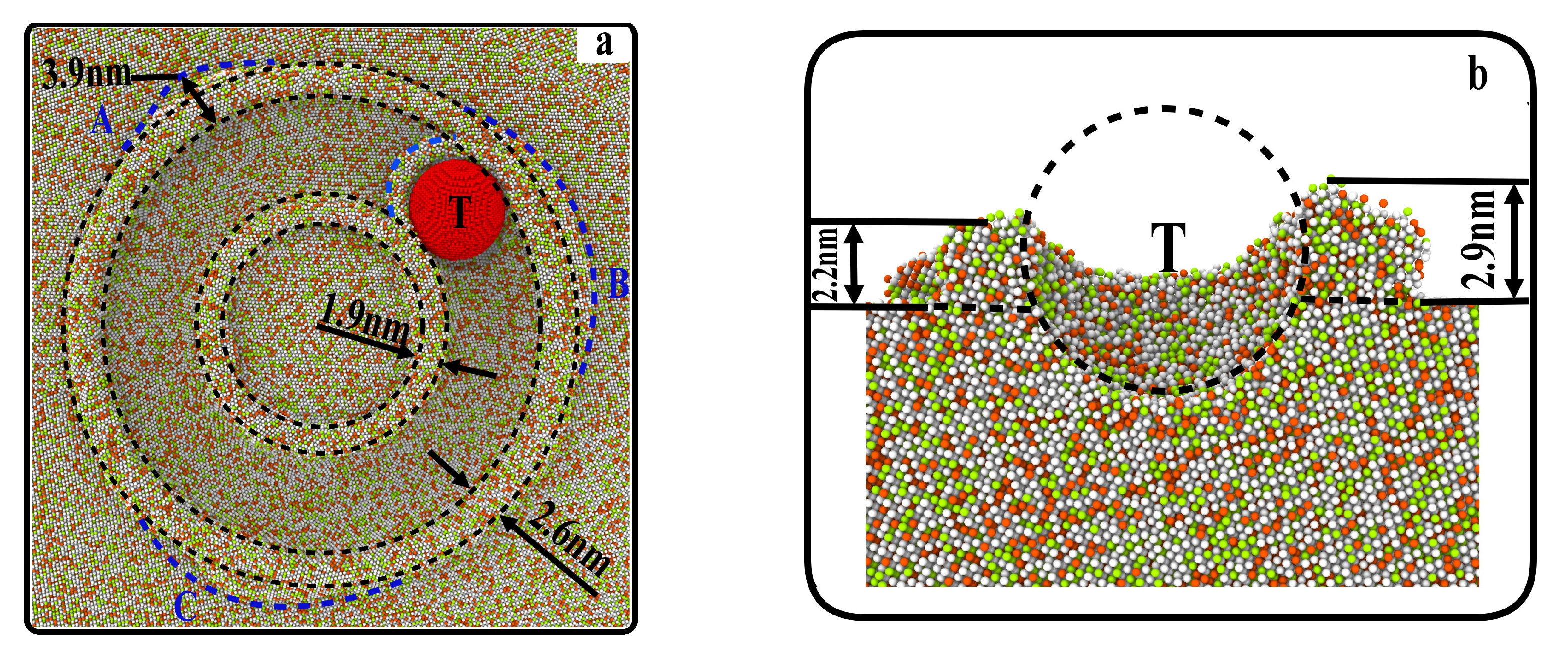
Figure 5a shows the overall topography after friction. It can be seen that the wear debris in front of the grinding ball is crescent shaped. The debris accumulation mainly flows to the outside of the grinding groove, while the debris formation in the inside is lesser. This is because the farther the debris atom in front of the ball is from the center of rotation, the greater the centrifugal force, and it is thus easier to be separated to the outside by the ball. In addition, the thickness of the outside chip atoms is not uniform, and there are obviously protruding chip atoms, as shown at A, B and C in Figure 5a. Due to the movement direction not being consistent with the direction of the most easily sliding surface of the atoms in the grain, an increase of frictional force of the grinding ball is observed; the debris generated by friction accumulates, which hinders the formation of frictional force and defects, thus making the outer debris form a convex accumulation at A, B and C. It can be seen from Figure 5b that the debris height of the inner and outer sides is 2.2 nm and 2.9 nm respectively, and the debris height of the outer side is greater than that of the inner side. This further indicates that the debris atoms are more likely to be distributed to the outer side, resulting in the debris height of the outer side being greater than that of the inner side. In order to further explore the detailed flow direction distribution of debris atoms, the following is to analyze the displacement vector of debris atoms.
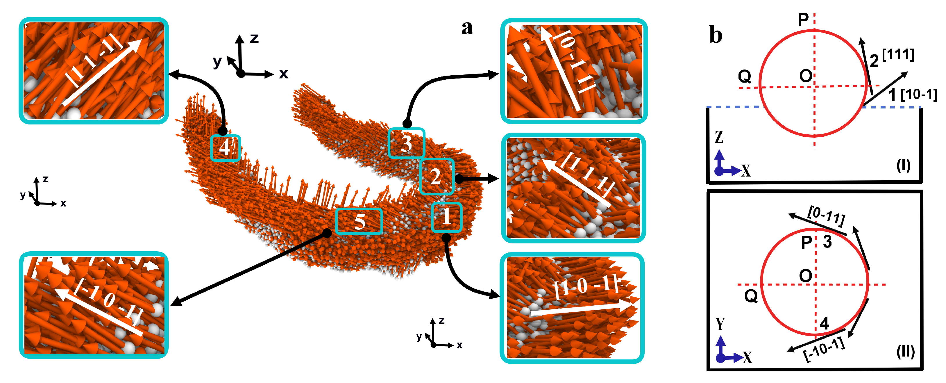
Figure 6a shows the displacement vector diagram of atom debris, and Figure 6b is the diagram of atom flow corresponding to Figure 6a. There are obviously different atomic displacement trends in Figure 6a. It can be seen that the atomic displacement at position 1 is along the [10−1] direction. These atoms are located below the maximum horizontal radius of the grinding ball, mainly squeezed by the grinding ball, resulting in displacement trend along the oblique top of the direction of motion. It is the main source of power for the development of defects to the non-friction area on the surface. The atomic displacement at position 2 is along the [111] direction in the Figure 6a, and moving obliquely backward along the surface of the grinding ball. This is because the atoms at point 2 are located at the maximum horizontal radius of the grinding ball, at this time, it is pushed by the atoms at position 1 to make it move upward. With the debris continue to increase, both sides begin to split, forming atoms at positions 3 and 4 along the [0−11] and [−10−1] direction. These two parts of atoms mainly flow to the inner and outer sides of the grinding groove, and repeated friction causes the accumulation of wear debris. Finally, the abrasive debris atoms on both sides are distributed to 5 positions, and the atomic displacement is in the direction of [11−1]. In this moment, there is no friction and extrusion of the grinding ball, these atoms begins to elastically recover and move to the inside of the grinding groove.

3.3. Grinding Groove Morphology and Defects

Figure 7 shows the depth of the grinding groove after three applications of friction. It can be seen that the depth of the grinding groove increases rapidly at the beginning of friction. When the grinding ball is rubbed from the initial position to 20 degrees, the depth of the grinding groove tends to be stable and fluctuating. This is because the grinding ball starts to press down, and the damage to the workpiece material increases continuously. In addition, during the first friction that the fluctuating amplitude of the grinding groove is larger, and the average depth is deeper than that of the last two frictions. The reason is during the first friction that the workpiece after fully relaxation at this time has no residual stress on the surface, which has less hindrance to the grinding ball and removes more material. Due to the influence of the grain boundary and the depth of the grinding groove changes in a wave shape, as shown in Figure 7. This shows that the grain boundary has an obstructive effect on the movement of the grinding ball. The internal stress and the potential energy of the atoms at the grain boundary are higher than the internal [27], which leads to the strengthening effect of the grain boundary in the workpiece [28]. Herein, we move on to further analysis of the number of atoms of wear debris after repeated friction.
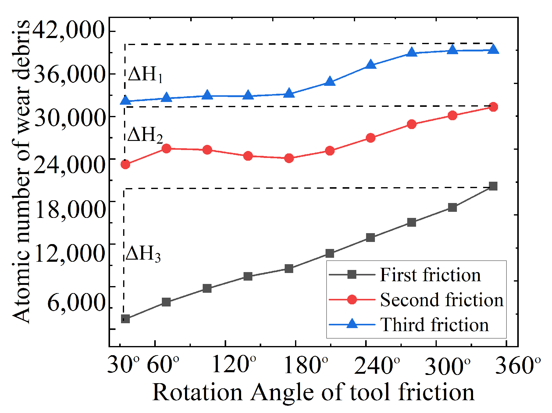
Figure 8 shows the number of wear debris atoms after three frictions. It can be observed from the figure that, after the grinding ball rubs the workpiece three times, the slopes of the three curves increase linearly and positively. In the first friction, the most debris atoms are removed, while in the repeated friction, the number of debris atoms decreases in turn. This is because the grinding ball and the workpiece are in saturation contact during the first friction, and the contact area between the grinding ball and the workpiece is larger, so more debris atoms are removed. When friction is repeated, more grinding heat is generated due to the first friction, which leads to deformation of the surface of the workpiece, and leaving residual stress on the surface layer, which increases its hardness. Therefore, the wear debris atoms during repeated friction decrease sequentially.
In order to explore the micro-change mechanism of the grain boundary on the formation of defects, this paper studies the nucleation change law of the internal defects of the workpiece when the grinding ball rubs to the grain boundary. 
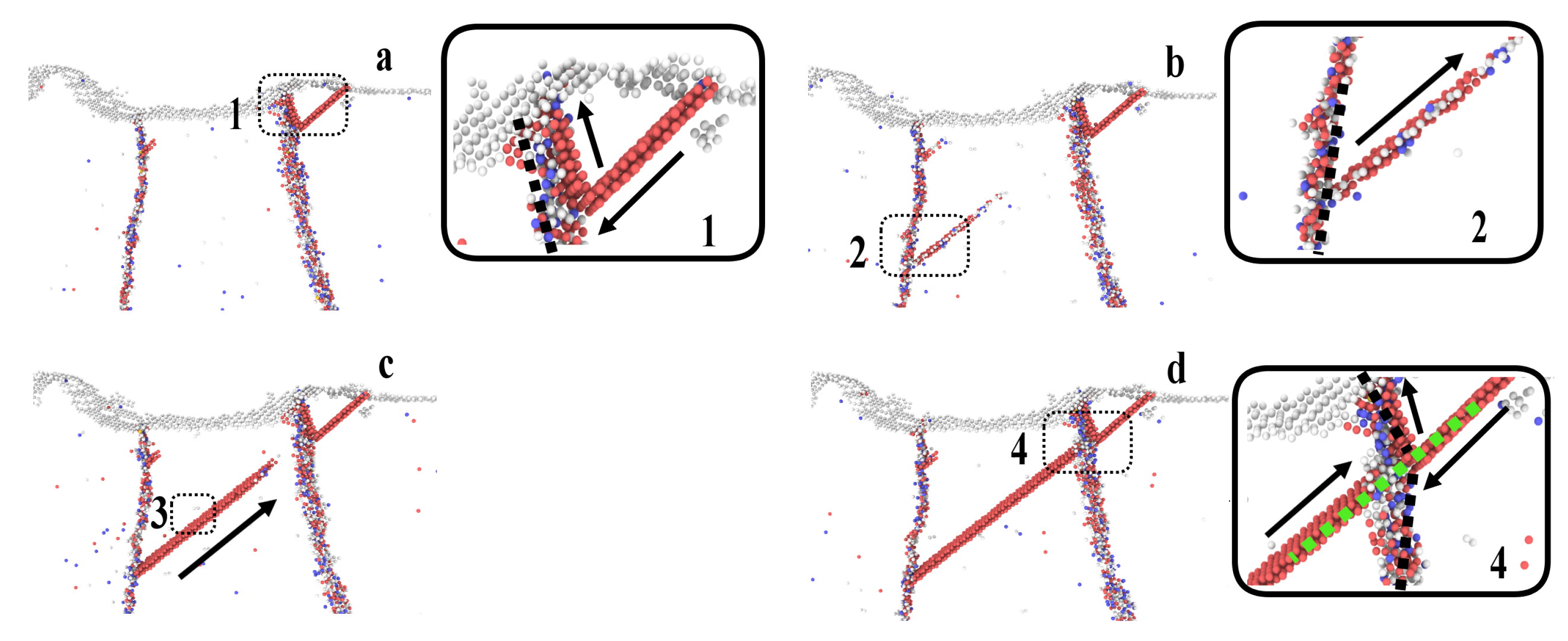
Figure 9 shows the process diagram of the grain boundary affecting defect nucleation. It can be seen in Figure 9a that the nucleation defect begins under the surface of the workpiece (shown at position 1). With the friction of the grinding ball, the defect develops inward until it reaches the grain boundary interface, where the grain boundary blocks the expansion of dislocation slip, as shown by 1 in Figure 9a. This is due to the strengthening effect of the grain boundary, and it forms a barrier to the development of stacking fault defects, so that the defects cannot pass through the grain boundary [29]. However, a new defect is formed at the other side of the grain boundary, which is coplanar with the most slippery surface in the direction of the defect, as shown by 2 in Figure 9b.
This is because with the friction of grinding ball that the internal energy of the workpiece increases continuously. Although the stacking fault defect at this point cannot pass through the grain boundary, the slip of the upper fault has, in fact, been extending and transferring energy forward, resulting in the formation of new stacking fault defects. The grain boundary on the left blocks the stacking fault defects again, which makes the reverse accumulation and extension increase at the grain boundary, as shown at 3 in Figure 9c. Finally, the defects extend to the right grain boundary and that is destroyed when the energy collected by stacking faults is strong enough, as shown by 4 in Figure 9d. A channel for releasing energy is formed and the energy inside the workpiece is released on the friction surface.
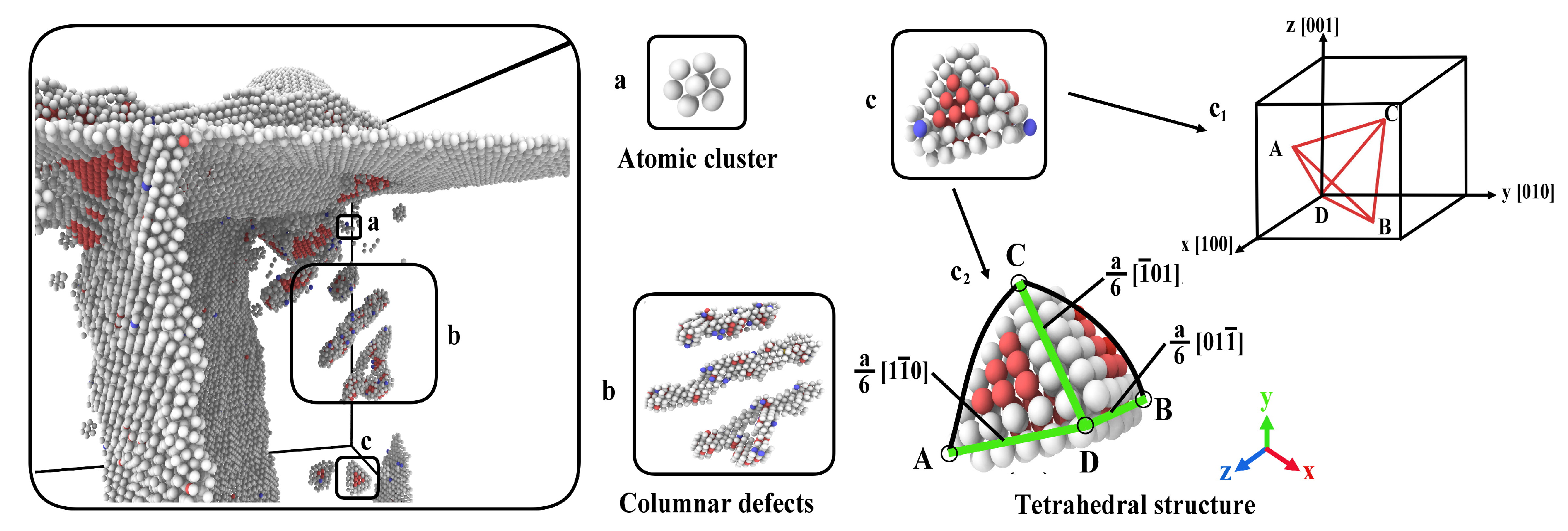
Figure 10 shows the different kinds of defects in the workpiece after the grinding ball rubs across the grain boundary. It can be seen from the Figure 10a is an atomic cluster [11], Figure 10b is a columnar dislocation defect [23], and Figure 10c is the stacking fault tetrahedron [25]. The reason is that with the increase of grinding heat caused by friction, the migration rate of atoms in the workpiece is accelerated and the defect atoms attract each other and stack tightly to form atomic clusters and columnar dislocation defects. In addition, the stored energy starts to release, which makes the dislocation defect move towards the friction surface. The subsurface stress drives the dislocation nucleation and finally induces the formation of stacking fault tetrahedron. Crystal planes (11−1), (1−11), (−111) and (111) are the four slip planes of FCC crystal, as shown in Figure 10c1. The dislocations generated during friction mainly move on the four slip planes. With the development of friction, the tetrahedron does not change its shape and size because this special and complex defect structure has its own stability.
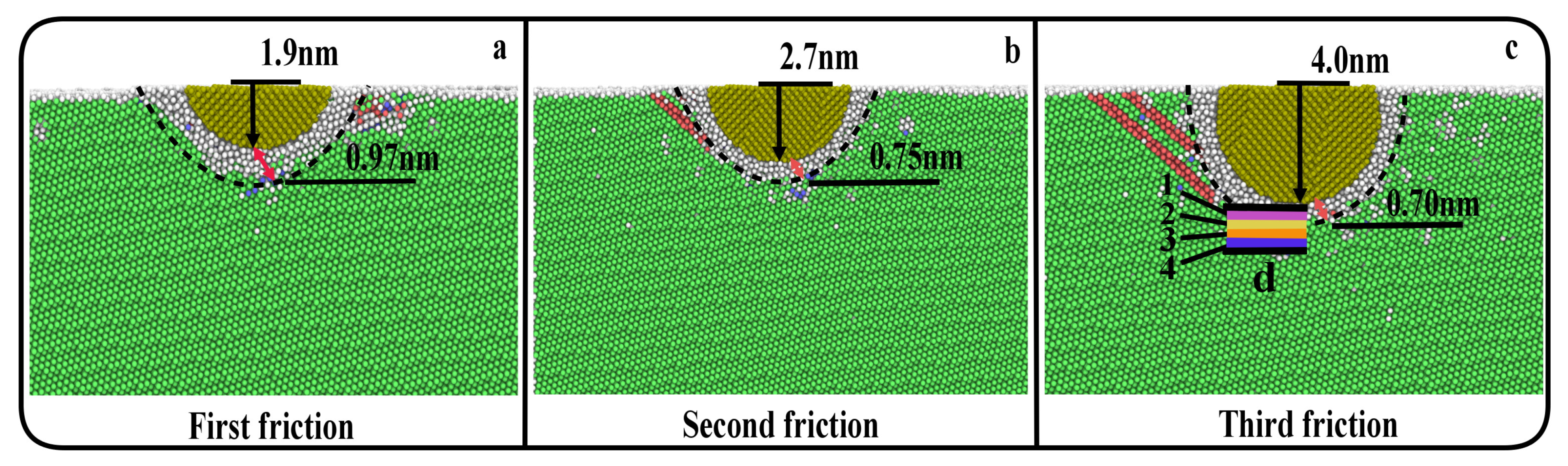
The defect atoms at the bottom of the grinding ball are important indicators that affect the quality of the subsurface. Figure 11 shows the cross section of grinding ball position after three times of friction. It can be observed from the figure that the depth of grinding ball is increasing, while the thickness of the metamorphic layer at the bottom decreases in turn. After the first two times of friction, the thickness of metamorphic layer changes greatly, but the latter two times change little. This is because when the grinding ball first rubs, there is no residual stress in the workpiece after relaxation and the degree of plastic damage of the workpiece is large. This results in a large range of defect layer at the bottom. The second and third friction is the repeated friction on the machined surface. Due to the phenomenon of cooling and hardening, a large amount of residual stress remains on the friction surface, which results in higher surface hardness and strong resistance to deformation. This hinders the movement of the grinding ball, so the defect thickness is further smaller.
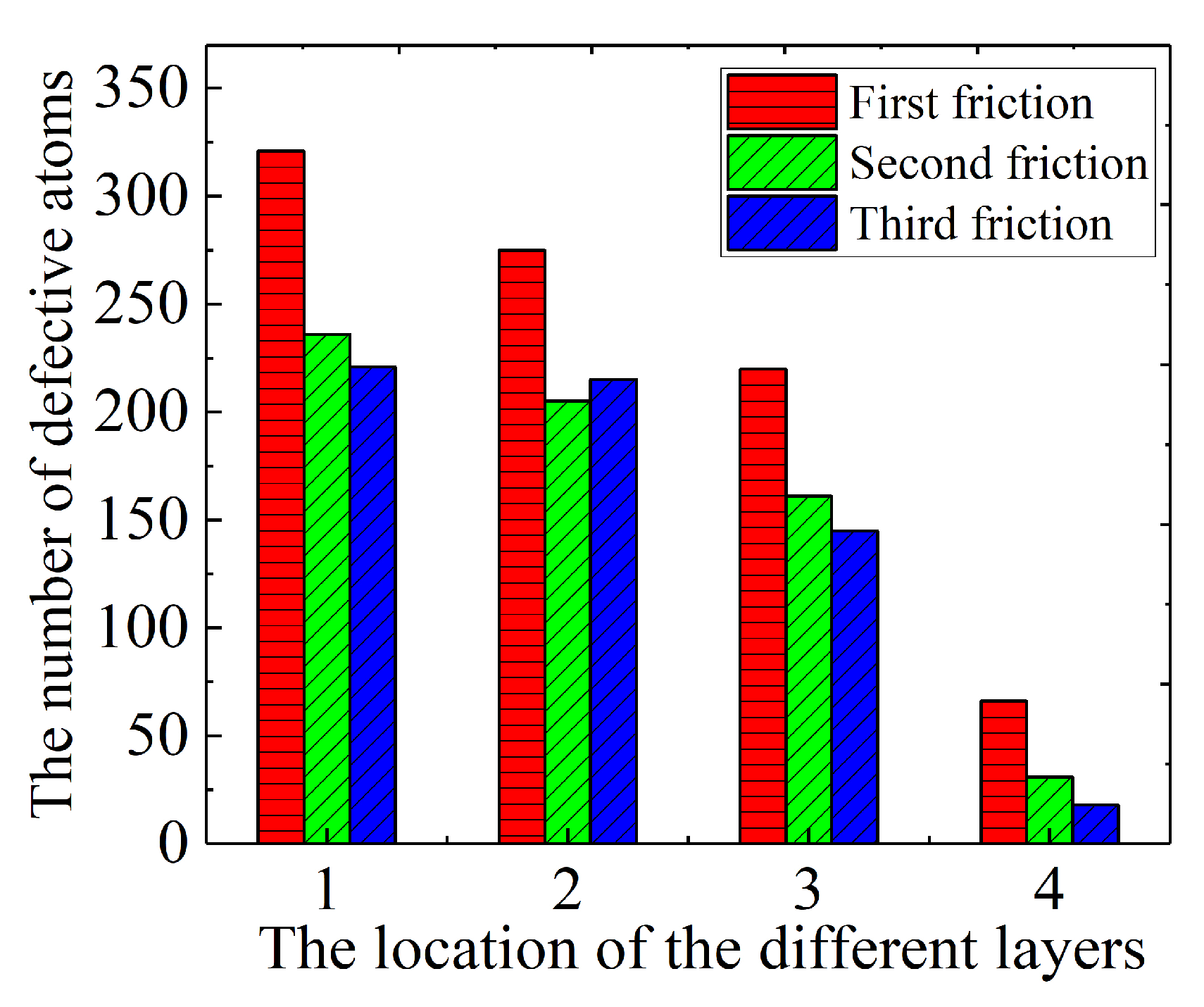
In order to further accurately analyze and judge the main location of subsurface defect atoms. Stratified statistics were made for the subsurface atoms after three frictions, as shown by d in Figure 11c. It is divided into four layers and each layer with a thickness of 0.35 nm. The number of defect atoms in different layers is obtained, as shown in Figure 12. It can be observed from the figure that the number of defective atoms at position 1 is the most and at layer 4 is the least. This is due to the temperature and energy produced in friction process are transferred to the higher layer 1, which has the largest damage degree, resulting in the most defective atoms. The atoms in layer 4 are far away from the grinding ball, so fewer defective atoms are generated. Moreover, in the same layer, the number of defect atoms produced by the first and second friction changes greatly, while the number of defect atoms produced by the last two friction changes little. When rubbing the workpiece just after relaxation for the first time, the damage to the workpiece atoms is large, resulting in more defective atoms generated. However, the last two frictions are repetitive frictions on the machined surface, and it can be seen that repeated friction causes less damage to the interior of the workpiece.
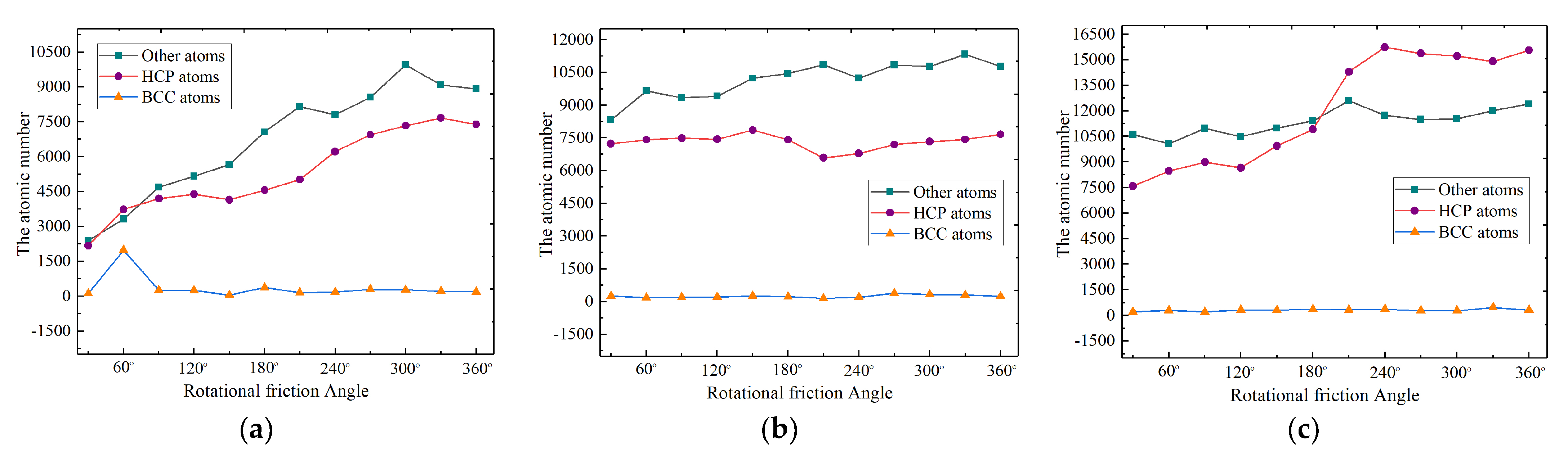
Figure 13 shows the number of HCP, BCC and other defects in the workpiece after three frictions. It can be seen from the figure that the number of HCP and other defect atoms increases rapidly in the first friction, and the number of defect atoms increases slowly and tends to fluctuate in the second friction. It is clear that, when the grinding ball rubs the workpiece for the first time, the damage to the interior of the workpiece is greater. The energy stored inside increases, which causes the frequency of atomic thermal motion to accelerate, resulting in the formation of more defective atoms inside. The next two frictions are repeated frictions, and at this time, the internal energy release of the workpiece reaches an equilibrium state. Hence, the internal damage of the workpiece is less when the friction is repeated. When the grinding ball rotates to 240 degrees in the third friction, the number of HCP atoms increases rapidly. This is because a large number of stacking faults are accumulated due to the hindering effect of the grain boundary, as shown in Figure 13c. Corresponding to the previous Figure 7, it can be seen that the depth of grinding groove gradually decreases.

3.4. Friction Characteristics of Different Grain Sizes

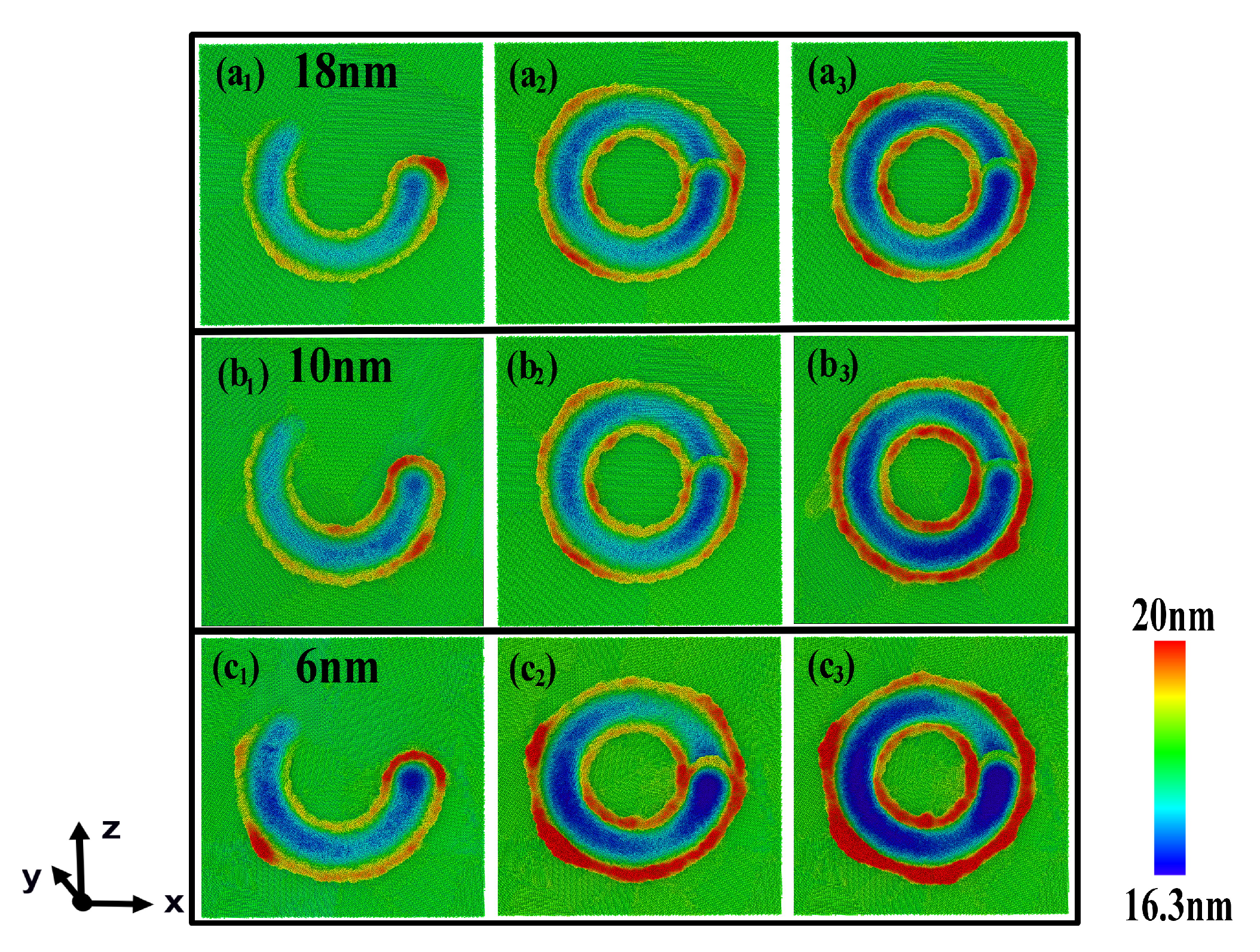
In order to further explore the changing characteristics when rubbing workpieces with different grain sizes, we color the displacement of the workpiece along the Z direction, as shown in Figure 14a1–c3. These are the surface topography of the workpiece, with grain size of 18 nm, 10 nm and 6 nm after three frictions, respectively. It can be seen that the grain size is 18 nm, the displacement of the chip atoms on the friction surface of the workpiece is large. When the grain size is 6 nm, the displacement of the atom becomes smaller.
This shows that as the grain size decreases during the friction process, the depth of the grinding groove gradually deepens. This is because the material softens as the grain size of polycrystalline nickel decreases [30]. First, polycrystalline materials follow the Hall–Petch relationship [31], leading to the hardening of polycrystalline materials. When the average grain size is below the critical value (approximately 15–25 nm for FCC metals), and the yield stress of the nanocrystalline material decreases with the decrease of the average grain size [32]. Polycrystalline materials will follow the anti-Hall–Petch relationship, and further reduction of grain size will lead to material softening. In this article, the material with smaller grain size is used, so the material softens during the friction process.
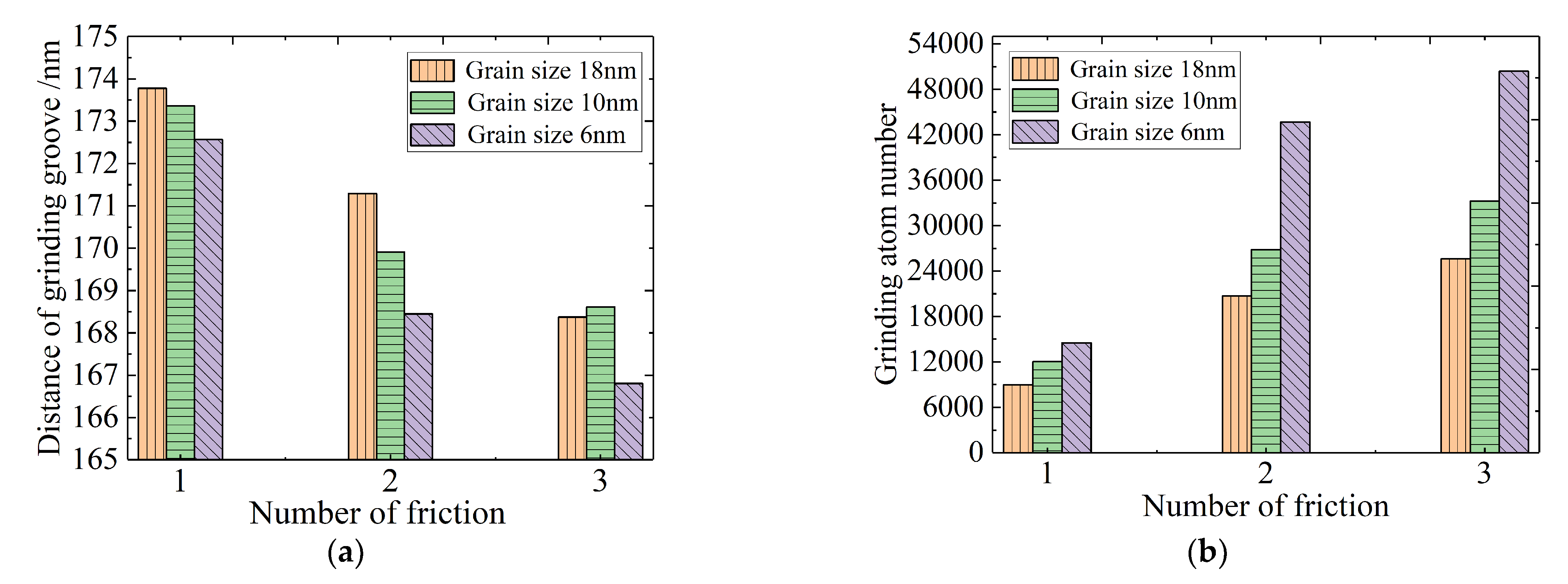
Figure 15 shows a bar graph of the depth of the grinding groove and the number of atoms of the discharged wear debris under different grain sizes. It can be seen from Figure 15a that the height of the orange, green, and purple histograms decreases in sequence, and the same pattern appears in the second and third repeated frictions. Corresponding to the atomic number chart of abrasive debris discharged in Figure 15b, the height of the three bar charts increases successively with the decrease of grain size. This shows that as the grain size decreases that the workpiece material tends to soften to a certain extent, and the friction causes the depth of the grinding groove to gradually deepen. Thus, the number of discharged debris atoms also increases. It is further verified that, with the decrease of grain size, polycrystalline materials follow a certain anti-Hall–Petch relationship [31].
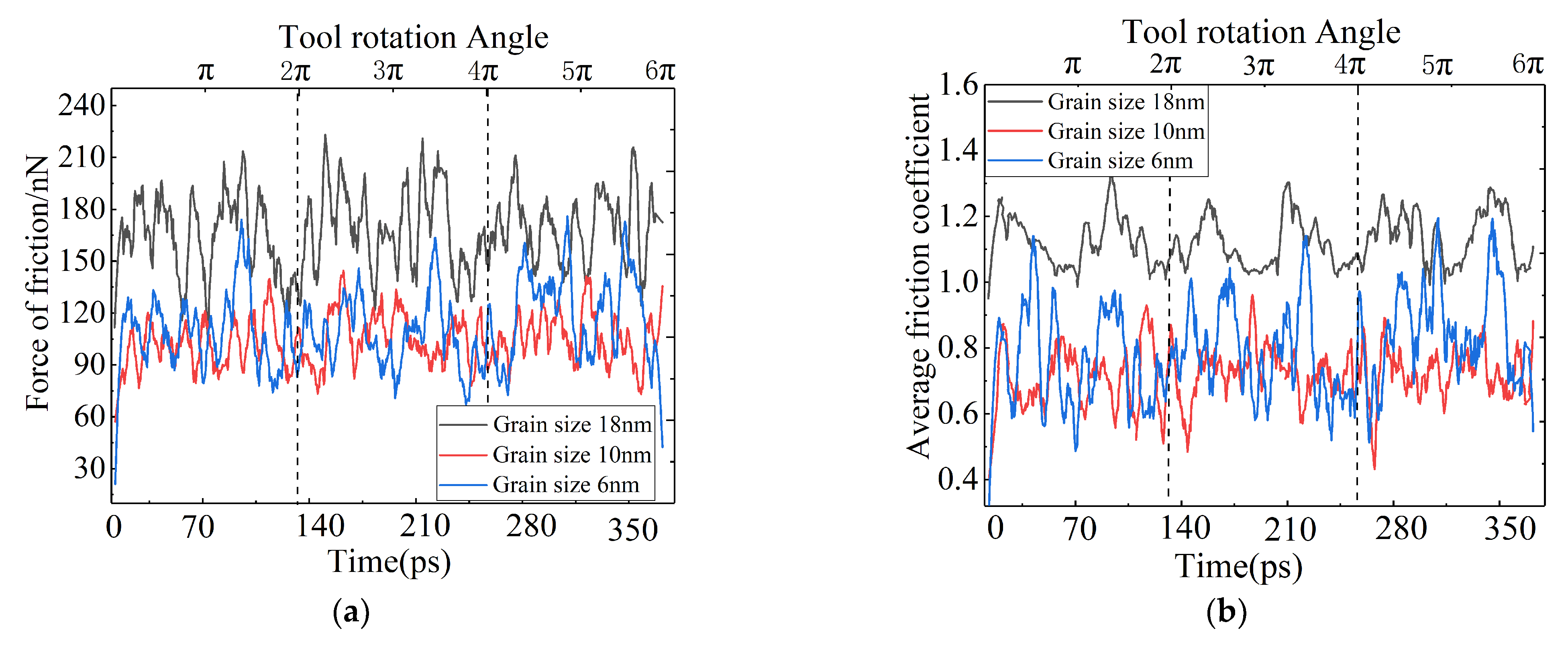
To further explore the changing law of frictional force and friction coefficient of workpieces with different grain sizes. In Figure 16a,b graphs of frictional force and average friction coefficient of different grain sizes are shown, respectively. When the grain size is 18 nm, the frictional force is the largest and fluctuates around 165 nN, as shown in Figure 16a. While the grain size is 6 nm, the frictional force is the least, and the curve fluctuates with high frequency and small amplitude. This is because as the grain size decreases and the workpiece material softens, resulting in the reduction of frictional force in the crystal. Due to the grain boundary hinders the movement of the grinding ball, which the friction force fluctuates with high frequency and small amplitude. Similarly, it can be seen in Figure 16b that the average friction coefficient values of the three curves fluctuate around 1.15, 0.85, and 0.70, which shows that as the grain size decreases, the material softens, and the average friction coefficient also decreases. Due to crystal orientation of polycrystalline materials being different, the frictional force and friction coefficient fluctuates and oscillates. This is because when the direction of grinding ball movement is parallel to the direction of the crystal, and thus, the frictional force is small, leading to a smaller friction coefficient. When the friction direction is inconsistent with the crystal orientation, the movement of the grinding ball is hindered by the crystal orientation, which increases the frictional force and friction coefficient [32,33,34]. This provides a theoretical basis for the study of the surface quality after different grain size friction and the wear force analysis of the grinding ball.
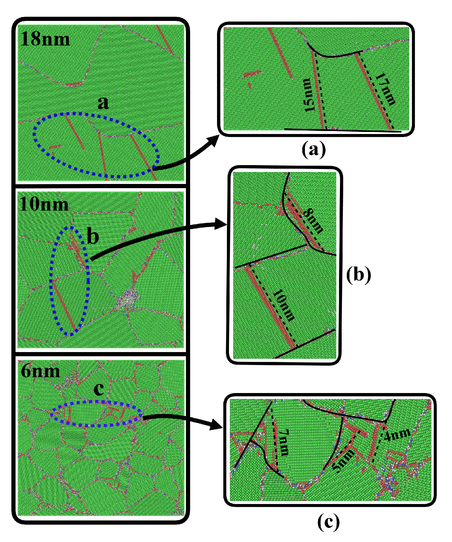
Figure 17 shows the internal damage diagram of the workopiece with different grain sizes. When the grain size is 18 nm, larger damage defects exist inside, as shown in Figure 17a. Instead, the grain size is 10 and 6 nm, and the damage defects inside the crystal also gradually become smaller, as shown in Figure 17b,c. However, it is mainly distributed between the grain boundary, which indicates that the smaller the grain size, the lesser the defect size inside the crystal. This is because in the process of dislocations being transferred inside the polycrystalline nickel matrix, there is a loosely distributed and disordered grain boundary structure in the polycrystalline nickel. The grain boundary structure can effectively hinder the dislocation structure expansion and absorb the energy generated in the friction process [35]. Therefore, the range of nucleation expansion of dislocation is restricted, leading to the distribution of dislocation defects between grain boundaries of the polycrystalline nickel matrix.
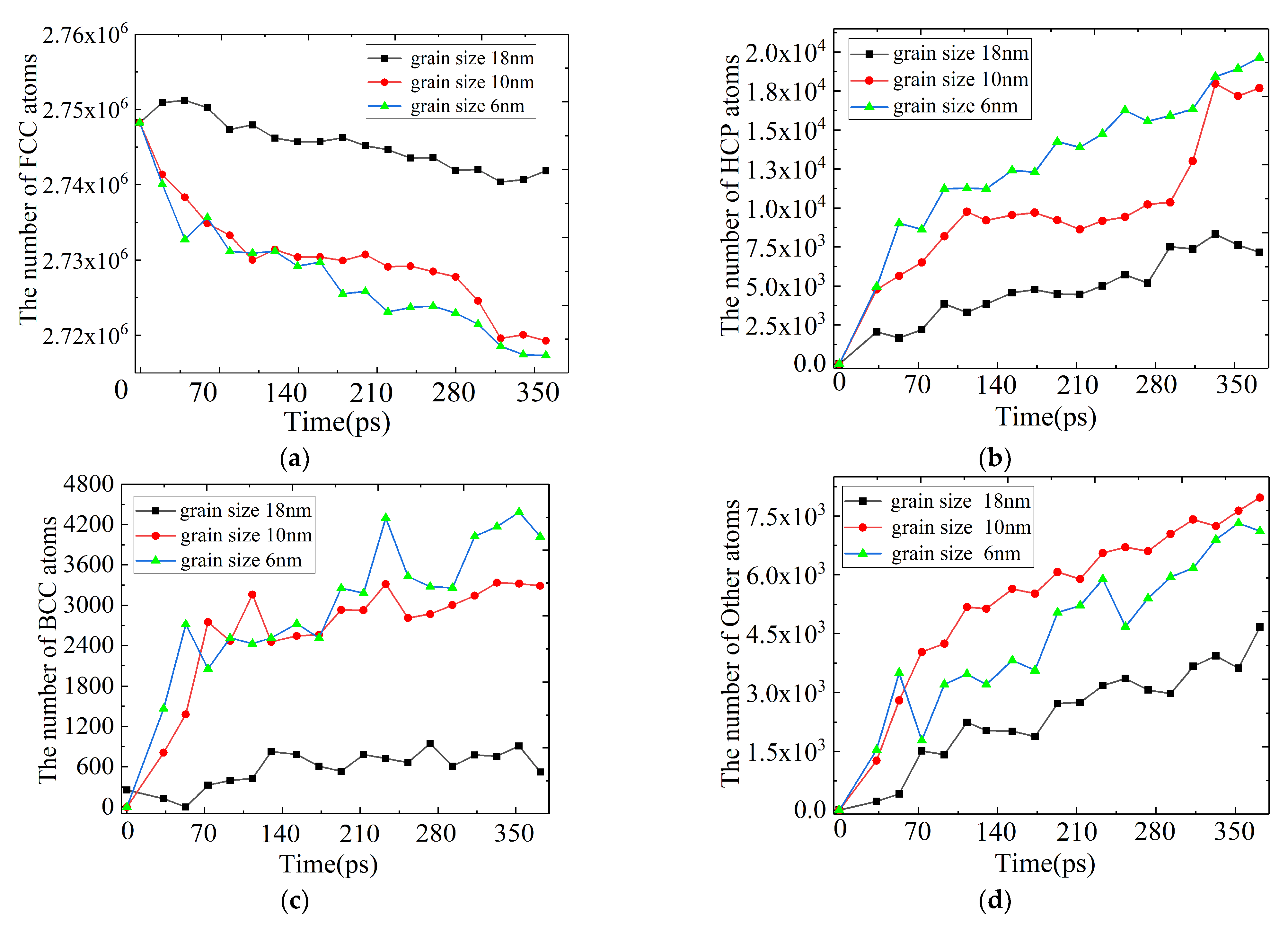
Figure 18a–d shows the changes in the number of FCC, BCC, HCP and amorphous defect atoms after third frictions. When rubbing a workpiece with a smaller grain size, it forms the largest number of body-centered cubic structure atoms and HCP atoms. In the workpiece with large grain size, the number of these atoms is small, and there is a big change in a certain stage. This is because when the grain size is small, the grain boundary structure inside the workpiece is more distributed, and the friction of the grinding ball causes the internal energy and temperature to increase. Due to the obstruction of the grain boundary, the migration of atoms is hindered, resulting in the formation of more defects at the grain boundary. In a workpiece with a large grain size, there is no obstruction by the grain boundary at this time, and larger dislocation defects will be generated during the friction process, resulting in an increase in the number of HCP atoms. According to the previous analysis, when the grain size is 10 nm, the friction workpiece material tends to soften. With the increase in the number of frictions, the friction and squeezing of the atoms of the workpiece further increases the energy and temperature of the internal atoms, which makes the atoms easy to be destroyed to form amorphous atoms, resulting in an increase in the generation of defects, and is positively correlated with the friction time step.

4. Conclusions

In this paper, the molecular dynamics simulation method was used for repeated friction of a polycrystalline nickel-based alloy, and compared with the results of previous researchers. The changes of friction force and friction coefficient during repeated friction, the microscopic mechanism of wear debris formation in materials, the influence of grain boundaries on friction morphology and defect nucleation, and the evolution process of internal dislocation defects were studied. In order to study the overall effect of grain size on nano-friction, three workpieces with different grain sizes were constructed. From the results obtained in this article, the following conclusions can be summarized:
When the value of Fx or Fy is 0, the component force in the other direction is not the maximum, but appears later, the change in the total frictional force is related to the direction of the dislocation slip. When the movement of the grinding ball is consistent with the direction of the dislocation slip, the total frictional force is the smallest at this time. The fluctuation of the friction coefficient becomes smaller when subjected to repeated friction.
The accumulation of wear debris is mainly formed on the outside of the grinding groove and outwardly convex and uneven thickness wear debris. Above the friction surface, the grinding ball has a shunting effect on the debris atoms, and the shunt point is located at the maximum horizontal radius. However, the debris atoms moving along the direction of friction velocity are the main source of damage to the non-friction region.
The grain boundary structure can improve the strength of nanocrystalline nickel, which can hinder the development of the dislocation nucleus. Repeated friction causes the surface hardening of the workpiece. In addition, the closer the atom is to the sub surface, the more damage the workpiece will be caused by friction. However, the damage to the workpiece is less when the friction is repeated.
When the workpiece with different grain size is rubbed, the material tends to soften with the decrease of grain size, which leads to the increase of wear scar depth and the decrease of frictional force and friction coefficient. Small defects are formed inside the workpiece, and they are mainly distributed around the grain boundaries. During repeated friction, the transformation rate of complete atoms into amorphous atoms slows down, while a large number of defects appear in the workpiece with larger grain size.

Author Contributions

Writing—original draft preparation, investigation, data curation, H.W. and Z.Z.; investigation, writing—review and editing, conceptualization, validation, L.W. and M.Z.; methodology, visualization, Z.Q. and S.Z.; data processing, J.C.; J.Y. and S.J. All authors have read and agreed to the published version of the manuscript.

Funding

This research was funded by the National Natural Science Foundation of China (51805513, 51835012), The Natural Science Foundation of Gansu Province, China (20JR5RA462), The Scientific Research Projects of Higher Education in Gansu Province, China (Grant No. 2018A-126).

Institutional Review Board Statement

Not applicable.

Informed Consent Statement

Informed consent was obtained from all subjects involved in the study.

Data Availability Statement

Data is contained within the article.

Conflicts of Interest

The authors declare no conflict of interest.

References

  1. Ding, W. Review on Grinding Technology of Nickel-based Superalloys Used for Aero-engine. Chin. J. Mech. Eng. 2019, 55, 189–215. [Google Scholar] [CrossRef]
  2. Kopec, M.; Kukla, D.; Yuan, X.; Rejmer, W.; Kowalewski, Z.L.; Senderowski, C. Aluminide thermal barrier coating for high temperature performance of MAR 247 nickel based superalloy. Coatings 2021, 11, 48. [Google Scholar] [CrossRef]
  3. Hao, Z.; Cui, R.; Fan, Y.; Lin, J. Diffusion mechanism of tools and simulation in nanoscale cutting the Ni–Fe–Cr series of Nickel-based superalloy. Int. J. Mech. Sci. 2019, 150, 625–636. [Google Scholar] [CrossRef]
  4. Shahmardani, M.; Hartmaier, A. Constitutive modeling of cyclic plasticity at elevated temperatures for a nickel-based superalloy. Int. J. Fatigue 2021, 151, 106353. [Google Scholar] [CrossRef]
  5. Murthy, H.; Garcia, D.B.; Matlik, J.F.; Farris, T.N. Fretting fatigue of single crystal/polycrystalline nickel subjected to blade/disk contact loading. Acta Astronaut. 2005, 57, 1–9. [Google Scholar] [CrossRef]
  6. Guo, X.; Zheng, W.; An, W.; Antonov, S.; Li, L.; Cormier, J.; Feng, Q. High temperature creep behavior of a cast polycrystalline nickel-based superalloy K465 under thermal cycling conditions. Materialia 2020, 14, 100913. [Google Scholar] [CrossRef]
  7. Victoria, M.M.; Anthony, E.J.; Chris, J.T.; Tresa, M.P. Recrystallization and the Development of Abnormally Large Grains After Small Strain Deformation in a Polycrystalline Nickel-Based Superalloy. Metall. Mater. Trans. A 2016, 47, 1566–1574. [Google Scholar]
  8. Lin, B.; Zhao, L.; Tong, J. A crystal plasticity study of cyclic constitutive behaviour, crack-tip deformation and crack-growth path for a polycrystalline nickel-based superalloy. Eng. Fract. Mech. 2011, 78, 2174–2192. [Google Scholar] [CrossRef] [Green Version]
  9. Bill, R.C. Fretting Wear and Fretting Fatigue—How Are They Related? J. Lubr. Technol. 1983, 105, 230–238. [Google Scholar] [CrossRef]
  10. Li, L.; He, K.; Sun, S.; Yang, W.; Yue, Z.; Wan, H. High-Temperature Friction and Wear Features of Nickel-Based Single Crystal Superalloy. Tribol. Lett. 2020, 68, 1–12. [Google Scholar] [CrossRef]
  11. Satoko, H.S.; Akira, Y.D.; Yanagimotom, J. Uniform Hot Compression of Nickel-based Superalloy 720Li under Isothermal and Low Friction Conditions: Forming Processing and Thermomechanical Treatment. ISIJ Int. 2020, 60, 2905–2916. [Google Scholar]
  12. Lai, M.; Zhang, X.; Fang, F. Crystal Orientation Effect on the Subsurface Deformation of Monocrystalline Germanium in Nanometric Cutting. Nanoscale Res. Lett. 2017, 12, 1–10. [Google Scholar] [CrossRef] [PubMed] [Green Version]
  13. Tian, S.; Zhu, X.; Wu, J.; Yu, H.; Shu, D.; Qian, B. Influence of Temperature on Stacking Fault Energy and Creep Mechanism of a Single Crystal Nickel-based Superalloy. J. Mater. Sci. Technol. 2016, 32, 790–798. [Google Scholar] [CrossRef]
  14. Arunachalam, R.; Mannan, M.A. Machinability of nickel-based high temperature alloys-machining science and technology. Mach. Sci. Technol. Int. J. 2007, 4, 127–168. [Google Scholar] [CrossRef]
  15. Fang, Q.; Wang, Q.; Li, J.; Zeng, X.; Liu, Y. Mechanisms of subsurface damage and material removal during high speed grinding processes in Ni/Cu multilayers using a molecular dynamics study. RSC Adv. 2017, 7, 42047–42055. [Google Scholar] [CrossRef] [Green Version]
  16. Yin, Z.; Zhu, P.; Li, B. Study of Nanoscale Wear of SiC/Al Nanocomposites Using Molecular Dynamics Simulations. Tribol. Lett. 2021, 69, 1–17. [Google Scholar] [CrossRef]
  17. Xu, Y.; Wang, M.; Zhu, F.; Liu, X.; Chen, Q.; Hu, J.; Lu, Z.; Zeng, P.; Liu, Y. A molecular dynamic study of nano-grinding of a monocrystalline copper-silicon substrate. Appl. Surf. Sci. 2019, 493, 933–947. [Google Scholar] [CrossRef]
  18. Wang, Y.; Tang, S.; Guo, J. Molecular dynamics study on deformation behaviour of monocrystalline gan during nano abrasive machining-sciencedirect. Appl. Surf. Sci. 2020, 510, 145–161. [Google Scholar] [CrossRef]
  19. Xiao, G.; He, Y.; Geng, Y.; Yan, Y.; Ren, M. Molecular dynamics and experimental study on comparison between static and dynamic ploughing lithography of single crystal copper. Appl. Surf. Sci. 2019, 463, 96–104. [Google Scholar] [CrossRef]
  20. Xu, F.; Fang, F.; Zhang, X. Effects of recovery and side flow on surface generation in nano-cutting of single crystal silicon. Comput. Mater. Sci. 2018, 143, 133–142. [Google Scholar] [CrossRef]
  21. Li, J.; Fang, Q.; Liu, Y.; Zhang, L. A molecular dynamics investigation into the mechanisms of subsurface damage and material removal of monocrystalline copper subjected to nanoscale high speed grinding. Appl. Surf. Sci. 2014, 303, 331–343. [Google Scholar] [CrossRef]
  22. Ren, J.; Hao, M.; Lv, M.; Wang, S.; Zhu, B. Molecular dynamics research on ultra-high-speed grinding mechanism of monocrystalline nickel. Appl. Surf. Sci. 2018, 455, 629–634. [Google Scholar] [CrossRef]
  23. Hao, S.; Tang, Q.H. Chip formation dependence of machining velocities in nano-scale by molecular dynamics simulations. Sci. China Technol. Sci. 2014, 57, 2426–2433. [Google Scholar]
  24. Foiles, S.; Baskes, M.I.; Daw, M.S. Embedded-atom-method functions for the fcc metals Cu, Ag, Au, Ni, Pd, Pt, and their alloys. Phys. Rev. B 1986, 33, 7983–7991. [Google Scholar] [CrossRef]
  25. Fan, Y.; Wang, W.; Hao, Z.; Zhan, C. Work hardening mechanism based on molecular dynamics simulation in cutting Ni–Fe–Cr series of Ni-based alloy. J. Alloy Compd. 2020, 819, 153331. [Google Scholar] [CrossRef]
  26. Zhu, Z.; Peng, B.; Feng, R.; Wang, L.; Jiao, S.; Dong, Y. Molecular dynamics simulation of chip formation mechanism in single-crystal nickel nanomachining. Sci. China Ser. E Technol. Sci. 2019, 62, 1916–1929. [Google Scholar] [CrossRef]
  27. Liu, X.; Zhang, H.; Lu, K. Formation of nano-laminated structure in nickel by means of surface mechanical grinding treatment. Acta Mater. 2015, 96, 24–36. [Google Scholar] [CrossRef]
  28. Shi, D.; Zhang, Z.; Hu, J.; Zhang, Z. Investigation on the grain boundary strengthening effect of a nickel-based superalloy. Fatigue Fract. Eng. Mater. Struct. 2020, 44, 822–831. [Google Scholar] [CrossRef]
  29. Wang, W.; Yuan, F.; Wu, X. Smaller critical size and enhanced strength by nano-laminated structure in nickel. Comput. Mater. Sci. 2015, 110, 83–90. [Google Scholar] [CrossRef] [Green Version]
  30. Zhao, P.Y.; Guo, Y.B.; Zhang, X.Q.; Liu, H.; Bai, Q.S.; Zhang, F.H. Influence of indentation position on the nanoindentation deformation mechanism of polycrystalline copper. J. Harbin Inst. Technol. 2018, 50, 11–16. [Google Scholar]
  31. Meyers, M.; Mishra, A.; Benson, D. Mechanical properties of nanocrystalline materials. Prog. Mater. Sci. 2006, 51, 427–556. [Google Scholar] [CrossRef]
  32. Yuan, Y.; Li, X.; Yang, W. Low-angle grain boundary structures and size effects of nickel nanolaminated structures. J. Mech. Phys. Solids 2019, 130, 280–296. [Google Scholar] [CrossRef]
  33. Zhu, K.H.; Zhang, X.Y.; Yuan, X.L. Orientation effect on friction behaviors of nano-single crystalline zirconium. Chin. J. Nonferrous Met. 2021, 31, 373–383. [Google Scholar]
  34. Dong, C.; Lu, X.; Yang, P.; Guo, X.; Ren, J.; Xue, H.; Li, J.; Tang, F.; Li, H.; Ding, Y.; et al. Effects of crystallographic orientation, temperature and void on tensile mechanical properties of Ni-Co single crystal nanopillars. J. Alloy. Compd. 2021, 870, 159476. [Google Scholar] [CrossRef]
  35. Zhou, K.; Liu, B.; Shao, S.; Yao, Y. Molecular dynamics simulations of tension–compression asymmetry in nanocrystalline copper. Phys. Lett. A 2017, 381, 1163–1168. [Google Scholar] [CrossRef]
Figure 1. Friction principle experimental device.
Coatings 11 00896 g001
Figure 2. MD simulation model for nanoscale grinding of nickel-based polycrystalline superalloy.
Coatings 11 00896 g002
Figure 3. Diagrams of each component and rotation diagram: (a) is variation of force component curve in the three directions and (b) is total friction and friction component.
Coatings 11 00896 g003
Figure 4. Frictional force and average friction coefficient during friction: a–d corresponding to point A–D in the frictional force curve, (a) is the stage of elastic deformation, (b) is the stage of plastic deformation, (c) is the direction of dislocation slip consistent with velocity, (d) is the direction of dislocation slip inconsistent with velocity).
Coatings 11 00896 g004
Figure 5. Debris accumulation morphology: (a) is the accumulation morphology diagram of debris atoms on the friction interface, and (b) is the height diagram of debris atoms inside and outside the abrasive particles.
Coatings 11 00896 g005
Figure 6. Displacement vector distribution diagram of abrasive debris atoms in front of the grinding ball: (b) is a schematic diagram corresponding to (a).
Coatings 11 00896 g006
Figure 7. Distance topography of wear marks.
Coatings 11 00896 g007
Figure 8. The number of atoms of debris expelled after three frictions.
Coatings 11 00896 g008
Figure 9. The effect of grain boundaries on the nucleation of defect dislocations, (ad) are the process of grain boundaries hindering the development of defects.
Coatings 11 00896 g009
Figure 10. Shows different types of defects formed at grain boundaries, and a, b, c are the formation of different types of special defects.
Coatings 11 00896 g010
Figure 11. Defects at the bottom of the grinding ball, and (ac) are the cross-sectional views of the grinding ball after three times of friction.
Coatings 11 00896 g011
Figure 12. The number of defect atoms in different layers after three times of friction.
Coatings 11 00896 g012
Figure 13. The number of HCP, BCC, and Other defective atom: (ac) are respectively the first friction, the second friction, and the third friction.
Coatings 11 00896 g013
Figure 14. Surface topography of workpiece with different grain size after three frictions, the grain size of the workpieces from (a–c) are 18 nm, 10 nm, and 6 nm respectively, and a1, b1, c1 are the first friction of the grinding ball, a2, b2, c2 are the second friction and a3, b3, c3 are the third friction.
Coatings 11 00896 g014
Figure 15. Friction of different grain size of the workpiece: (a) is the depth diagram of grinding groove after three frictions at different grain sizes, and (b) is the atomic number diagram of abrasive debris discharged at different grain sizes.
Coatings 11 00896 g015
Figure 16. Frictional force and friction coefficient with different grain sizes, (a) is the frictional force diagram and (b) is the friction coefficient diagram.
Coatings 11 00896 g016
Figure 17. Internal damage of workpiece with different grain size after three frictions and figures (ac) are the internal damage diagrams of different grain sizes.
Coatings 11 00896 g017
Figure 18. The change of the number and types of defect atoms with different grain sizes, and (ad) are the number of atoms of fcc, hcp, bcc, and other respectively.
Coatings 11 00896 g018
Table 1. Modeling parameters used in the simulations.
MaterialsPolycrystalline Nickel Alloy
Workpiece dimensions43 nm × 43 nm × 20 nm
Constant load85 nN
Grinding speed70 m/s
Initial temperature293 K
Time steps1 fs
Atomic number of workpiece4.13 × 106
Atomic number of tool5.6 × 104
Table 2. Morse parameters between several elements.
D(ev)A(1/Å)r0(Å)
C-C2.42302.55502.5220
C-Ni1.00391.98752.6199
C-Fe1.00571.97182.6493
C-Cr1.03422.06362.6176
Ni-Fe0.41891.40422.8123
Ni-Cr0.43081.49602.7658
Publisher’s Note: MDPI stays neutral with regard to jurisdictional claims in published maps and institutional affiliations.

