Article

Low-Temperature Large-Area Zinc Oxide Coating Prepared by Atmospheric Microplasma-Assisted Ultrasonic Spray Pyrolysis

1
Department of Mechanical Engineering, National Cheng Kung University, Tainan 70101, Taiwan
2
Department of Fiber and Composite Materials, Feng Chia University, Taichung 40724, Taiwan
*
Authors to whom correspondence should be addressed.
Coatings 2021, 11(8), 1001; https://doi.org/10.3390/coatings11081001
Submission received: 18 July 2021 / Revised: 15 August 2021 / Accepted: 20 August 2021 / Published: 22 August 2021
(This article belongs to the Special Issue Intelligent Tribological and Functional Coatings)

Abstract

:

Featured Application

An integrated programmable automated atmospheric microplasma-assisted ultrasonic spray pyrolysis system was successfully developed and used to prepare large-scale transparent conductive zinc oxide films.

Abstract

Zinc oxide (ZnO) coatings have various unique properties and are often used in applications such as transparent conductive films in photovoltaic systems. This study developed an atmospheric-pressure microplasma-enhanced ultrasonic spray pyrolysis system, which can prepare large-area ZnO coatings at low temperatures under atmospheric-pressure conditions. The addition of an atmospheric-pressure microplasma-assisted process helped improve the preparation of ZnO coatings under atmospheric conditions, compared to using a conventional ultrasonic spray pyrolysis process, effectively reducing the preparation temperature to 350 °C. A program-controlled three-axis platform demonstrated its potential for the large-scale synthesis of ZnO coatings. The X-ray diffraction results showed that the ZnO coatings prepared by ultrasonic spray pyrolysis exhibited (002) preferred growth orientation and had a visible-light penetration rate of more than 80%. After vacuum treatment, the ZnO reached a 1.0 × 10⁻³ Ωcm resistivity and a transmittance of 82%. The tribology behavior of ZnO showed that the vacuum-annealed coating had a low degree of wear and a low coefficient of friction as the uniformly distributed and dense coating increased its load capacity.

1. Introduction

Zinc oxide (ZnO) is a direct bandgap semiconductor material in the II–VI family of semiconductor compounds. It has a low free-radical excitation binding energy, a high melting point, good thermal conductivity, superior semiconducting characteristics, piezoelectric behavior, and photoconductive properties. Furthermore, ZnO exhibits a high penetration rate in the visible region, high muscular bonding strength, and high chemical stability. In addition, ZnO is a non-toxic material that is easily accessible at a low price. Consequently, ZnO is widely used in various applications, such as plasmonic metamaterials [1], laser materials [2], ultraviolet light sources [3], solar cell counter-electrodes [4], and transparent conducting oxides (TCOs) [5,6].
Zinc and oxygen atoms in the C-axis direction are not symmetrically distributed, and there is a clear polar growth trend. Consequently, ZnO has polar surface characteristics, making it is easy to design processes to control crystal formation and growth behavior to obtain various novel nanostructures that enhance different photoelectric properties. The development history of TCOs is long and varied. Badeker used a sputtering method to prepare cadmium oxide (CdO) [7], while Rupprecht discovered that indium (In) could be vacuum evaporated on a quartz plate. Oxidation treatment at 700–1000 °C could produce a transparent and conductive indium oxide (In2O3) film, the conductivity resulting from crystal defects [8]. In 1968, Groth and Van Boort found that the resistivity of In2O3 doped with Sn ions was an order of magnitude lower than that of the original In2O3 film [9]. To increase the conductivity of semiconductor materials, compounds such as indium-doped tin oxide (ITO)—that is, using n-type doping—and aluminum-doped zinc oxide (AZO) and gallium-doped zinc oxide (GZO), using p-type doping were developed [10,11,12].
Many synthesis processes have been used to prepare ZnO nanostructures, including chemical vapor transport, sputtering, metal-organic chemical vapor deposition, pulsed laser deposition, and hydrothermal methods [13]. Commonly used large-scale TCO thin film processes include the sol–gel and spray pyrolysis methods [14]. In the sol–gel method, an easily hydrolyzed metal compound is hydrolyzed and polymerized to form a hydroxide suspension that is initially in a sol state before being condensed into a network solid, or gel state, and then undergoing high-temperature treatment to obtain oxides [15]. Spray pyrolysis involves preparing the precursor of the object to be plated in a solution, which is materialized using an ultrasonic atomizer to form tiny droplets mixed with a carrier gas and sprayed onto a substrate. The substrate is heated to decompose the droplets to form a thin film. Spray pyrolysis is essential for temperature control and initial droplet control. An ultrasonic spray pyrolysis reaction mechanism model has been proposed, which assumes that the initial droplet size is fixed and changing the substrate temperature affects the results [16]. The main parameters are the selection of the precursor and the growth temperature. The precursor has enormous influence on the preferred crystal growth, with commonly used precursors being zinc chloride (ZnCl2), zinc acetate (Zn(CH3CO2)2), and zinc nitrate (Zn(NO3)2). All three precursors can prepare films uniformly at 550 °C. Zinc chloride (ZnCl2) is the most used precursor to synthesize ZnO coatings, forming a flaky hexagonal structure in the process. Under dry air conditions, ambient humidity affects its conversion temperature, which ranges from 420–460 °C [17].
The advantages of an atmospheric-pressure plasma (AP) source over a low-pressure process include the system modularization, mobility, and the potential to prepare large areas due to the absence of a vacuum system. In addition, high-energy substances in the plasma can break the chemical bonds, reducing the process temperature. The mechanism of nucleation and the growth of aerosol spray crystals in the plasma using AP techniques have already been investigated [18]. Precursor droplets undergo a chemical reaction through a plasma arc. When the gaseous substance is saturated, molecular collisions initiate primary nucleation after which the plasma charges them. After atomization, the droplet passes through the plasma flow, and the droplet’s surface is charged as a result of the self-diffusion effect [19]. As a result, the droplet surface has a redox reaction with the plasma, which reduces the growth temperature and synthesizes the nanocrystal [20].
An AP jet system using ZnCl2 as the precursor, nitrogen as the gas source, a voltage of 15 kV, and a frequency of 25 kHz was used to prepare a ZnO conductive film with a thickness of approximately 100 nm on a silicon substrate, a film resistivity of 1.4 Ωcm, and transmittance of more than 80% [18,21]. An AP jet system using Zn(NO3)2 as the precursor was supplied with a 120 kHz, 600 W power supply to form a plasma. A remote-type plasma was used as the reaction center to carry the precursor from the side carrier gas into the plasma. Thus, it prevents arc formation in the plasma reaction chamber, which damages the electrode from being corrupted by the reactants and the formation of an arc in the plasma [5,22].
The annealing environment has a significant impact on the properties of the film. The resistivity of ZnO film can be increased by two orders of magnitude when directly annealed in the air or reduced by five orders of magnitude when annealed in a vacuum. The structure of ZnO when annealing in the atmosphere is highly crystalline; oxygen is highly adsorbed at the crystalline surface to form a neutral defect, reducing the concentration of free carriers and leading to a decrease in conductivity, and thus, forming a hypoxia environment for vacuum annealing. Moreover, the excess oxygen atoms in the crystal boundary are released due to desorption, giving rise to oxygen voids that form free electrons, decreasing resistivity.
This study developed a system integrating conventional ultrasonic spray pyrolysis with an AP film preparation system. The aim is to reduce the preparation temperature of the ZnO coating using the ability of AP to decompose droplets. After vacuum annealing, the target specification of the ZnO was that of the TCO standard: 80% transmittance and resistivity of 1 × 10⁻³ Ω·cm.
The use of biodegradable or environmentally friendly materials and their composites as friction-reducing and anti-wear materials has continued to increase in recent years owing to environmental protection imperatives [23,24,25,26]. Moreover, the wear properties of these materials change with additives [27,28,29]. In addition to optoelectronics, ZnO film is often used as an anti-wear additive, such as in anti-wear coatings [30] and anti-wear additives in lubricating oils [31]. Furthermore, ZnO is often used with other materials, such as for abrasion and lubrication with graphene composite materials [25] and graphene/ZnO as a hybrid anti-wear additive [23,32].
Consequently, when ZnO materials are used for TCO applications, the material itself must have considerable anti-wear properties to increase its lifespan, in addition to the optical and electrical characteristics required to satisfy TCO standards.

2. Materials and Methods

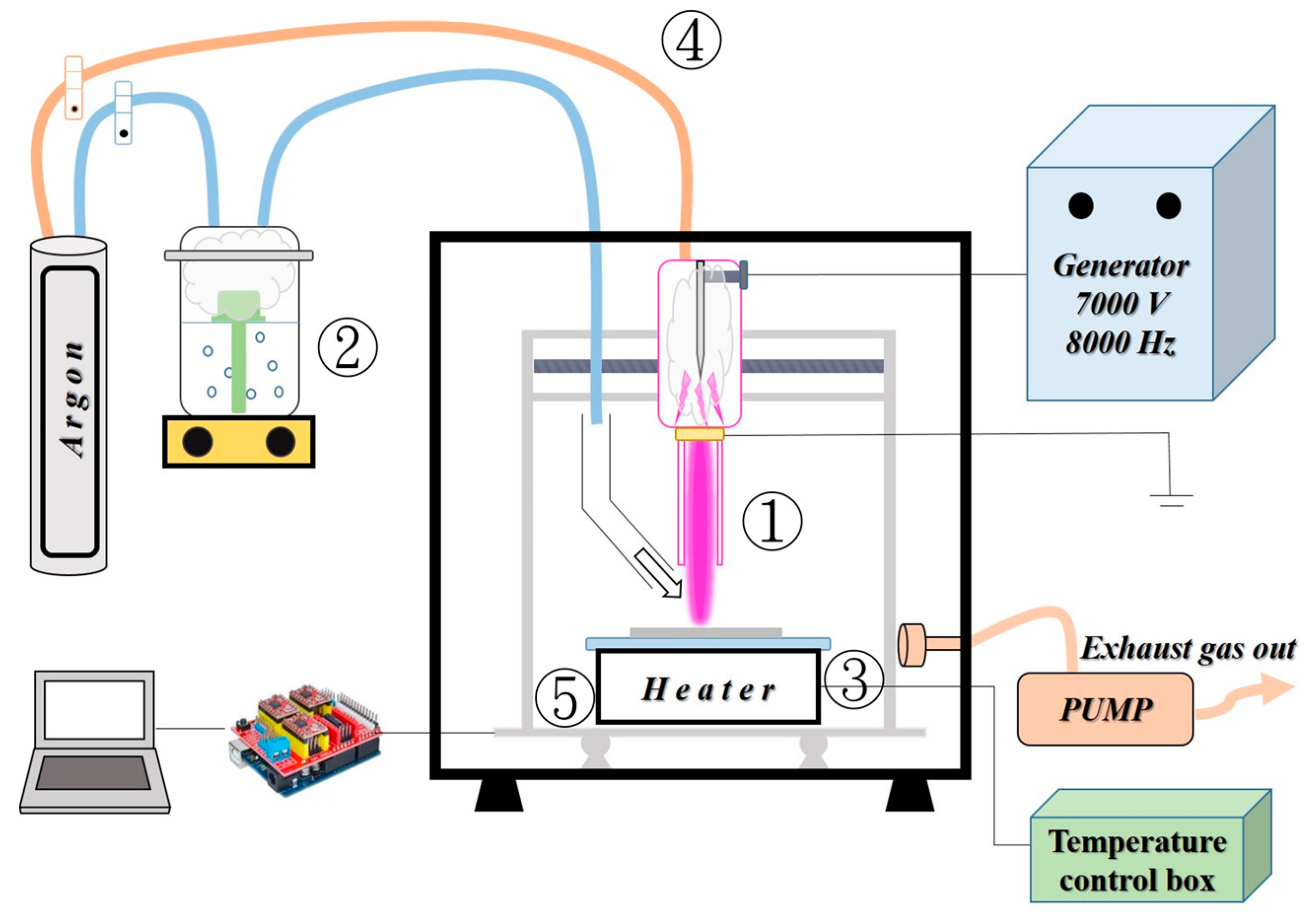
2.1. ZnO Coating Preparation

ZnCl2 (purity: 98%, SHOWA, Tokyo, Japan) was used as the precursor, prepared with ethanol to form a solution of 3 wt.%, after which an ultrasonic oscillator was applied for 10 min until the solution was transparent. A schematic of the atmospheric microplasma-assisted ultrasonic spray pyrolysis system is shown in Figure 1. The system comprised a homemade atmospheric microplasma jet (①), a mist generator (②), a heater (③), a gas delivery system (④), and an x-y-z three-axis moving stage (⑤). The atmospheric microplasma system consisted of a customized high-voltage AC power supply with a ten-fold high-voltage amplifier (Taiwan Plasma Corp., Kaohsiung, Taiwan). The front nozzle comprised a quartz tube with an inner diameter of 2.8 mm. A sharply pointed copper tungsten rod with a diameter of 1.6 mm was used as the internal electrode. A stable plasma flame was generated by applying an 8 kHz/7000 V AC voltage to a parallel argon flow at a flow rate of 4 L/min. The aqueous solution was atomized to form mists using an ultrasonic nebulizer with a 1.7 MHz transducer. The mists were injected downstream of the plasma jet by the 1.5 L/min argon gas guided by the quartz tube. Substrates of 10 × 10 cm2 soda-lime glass (Corning, Taiwan) were fixed to a heater and mounted on a three-axis moving stage. The moving stage was scanned at intervals of 0.8 mm at a rate of 2 mm/min using an Arduino controller. Thus, the area that could be scanned was 50 × 50 cm2.
Our study evaluated the influence of several deposition and annealing parameters such as the preparation temperature, atmospheric microplasma-assisted process, and annealing process. We referred to the literature for the conventional ultrasonic spray pyrolysis process and selected 450, 400, 350, and 300 °C as the process parameters for the ZnO coating preparation. With the aid of the atmospheric microplasma process, we attempted to reduce the overall process temperature from 400 °C to 350 °C. The prepared ZnO was subjected to rapid thermal annealing (RTA, Kao Duen Technology, Taipei, Taiwan). The annealing furnace was pumped to 0.05 Torr using a vacuum pump before heated to 600 °C for 1 h.

2.2. Analysis of ZnO Coating

Surface morphology and element analysis were performed using a 15 kV ultrahigh-resolution field-emission scanning electron microscope (HRA-SEM, SU-5000, Hitachi, Tokyo, Japan) at a working distance of 15 mm. Structural characterization was undertaken using a Bruker diffractometer, Model D2 phaser, using CuKα (Kα1, 0.15406 nm) at an operating voltage and current of 30 kV and 10 mA, respectively. The electrical properties of the films were measured using Hall effect analysis (AHM-800 B, Agilent Technologies, Santa Clara, CA, USA). In addition, the film transmittance, free carrier concentration, and energy gaps were measured using ultraviolet-visible spectroscopy (UV-Vis-NIR, U4100, Hitachi, Tokyo, Japan).

2.3. Tribology Behavior Analysis

The wear behavior of the ZnO thin films was determined using a ball-on-disk tribometer (POD-FM406-10NT, Fu Li Fong Precision Machine, Kaohsiung, Taiwan). A 52100 chrome steel ball (Φ = 6.31 mm) was used as the friction counterpart. The loading was set to 2 N, and the sliding speed was set to 0.03 m/s with a rotation radius of 3 mm. A wear test was conducted in a dry environment at 25 °C and a relative humidity of 70%. The friction coefficient of the coating was monitored and recorded in real time using sensors located on the testing machine. In addition, the wear width volume was measured using an ultrahigh-resolution scanning electron microscope (UHRFE-SEM, AURIGA, Carl Zeiss AG, Jena, Germany). The final experimental results obtained were the average of three sets of experimental data.

3. Results and Discussion

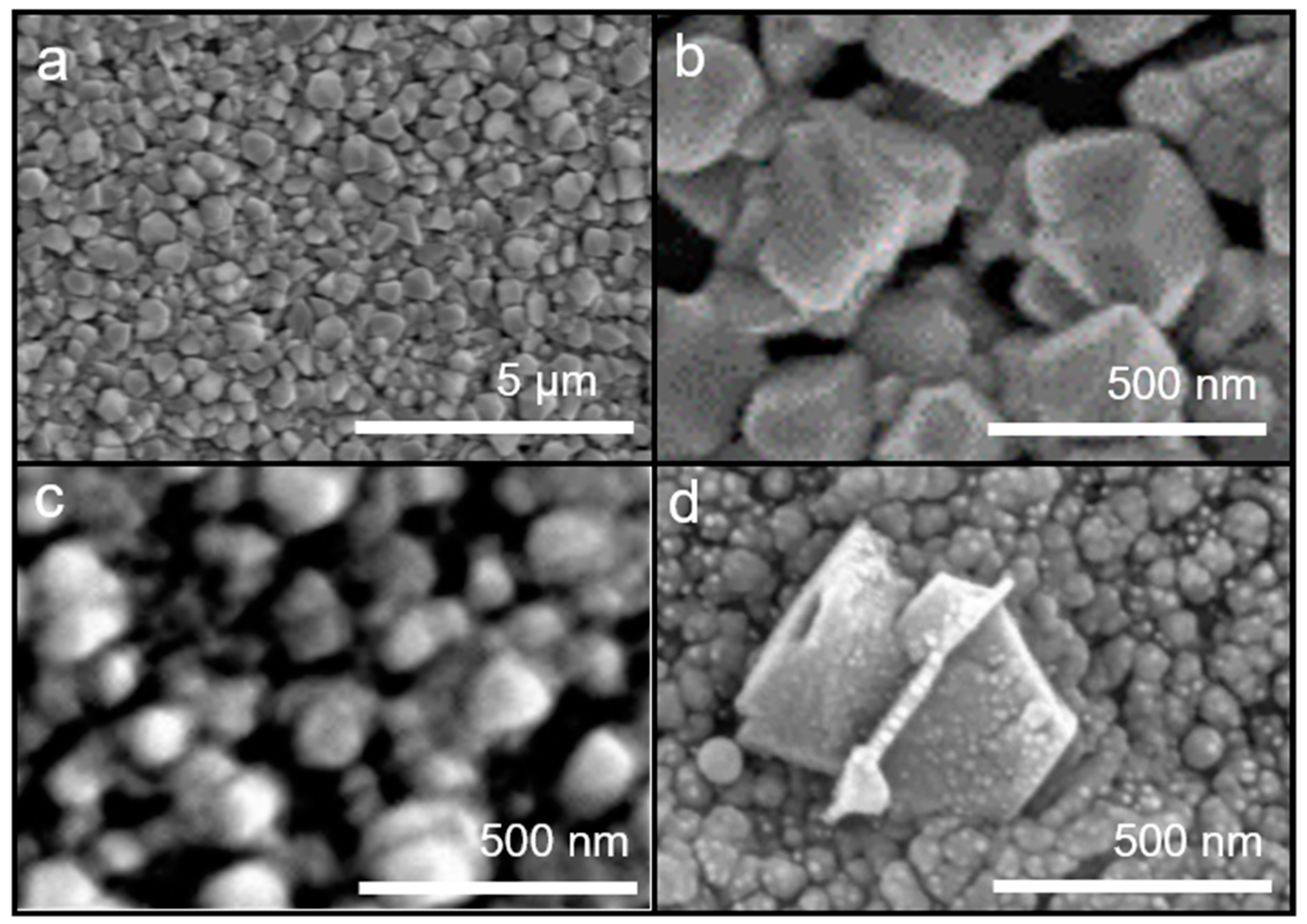
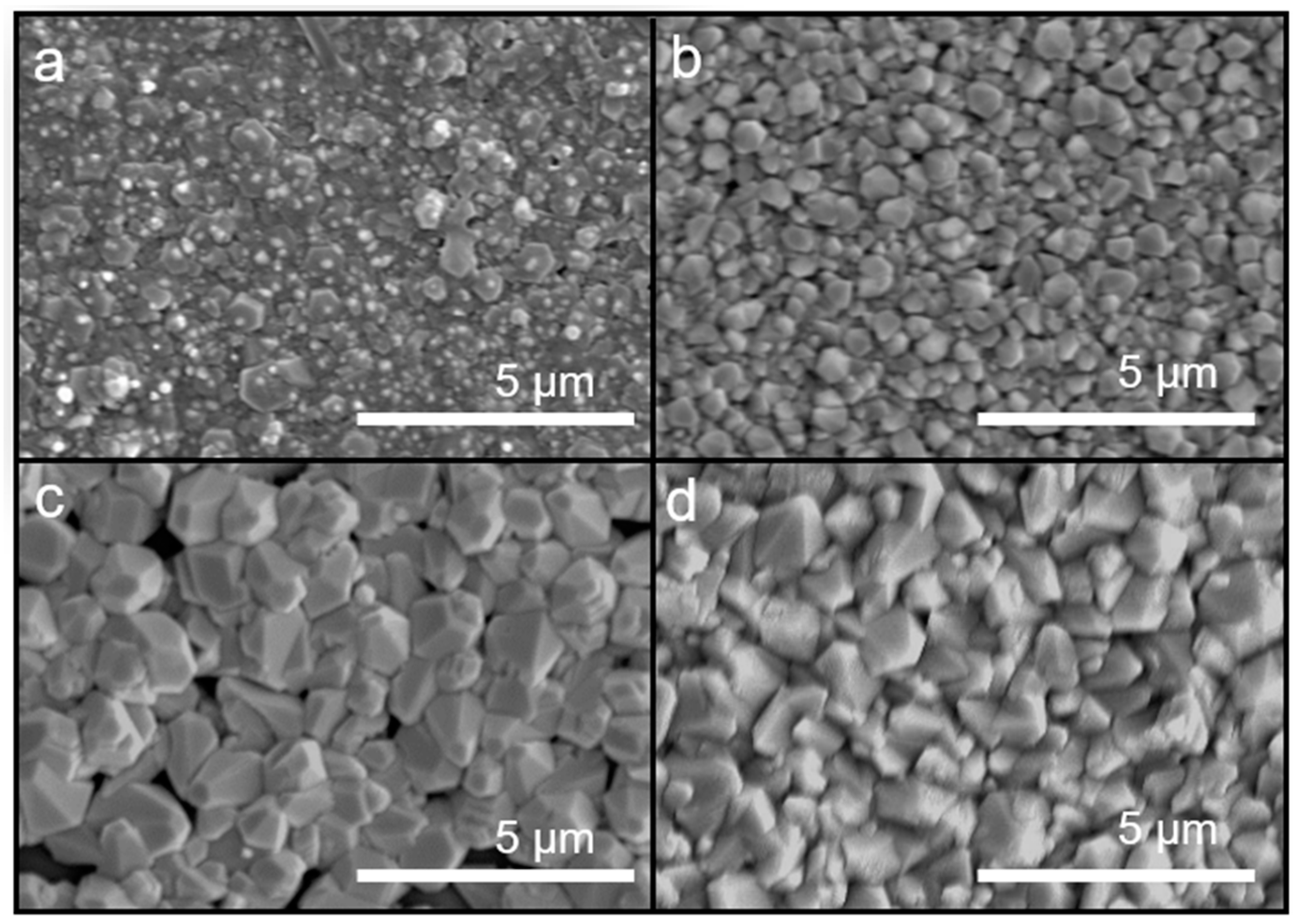
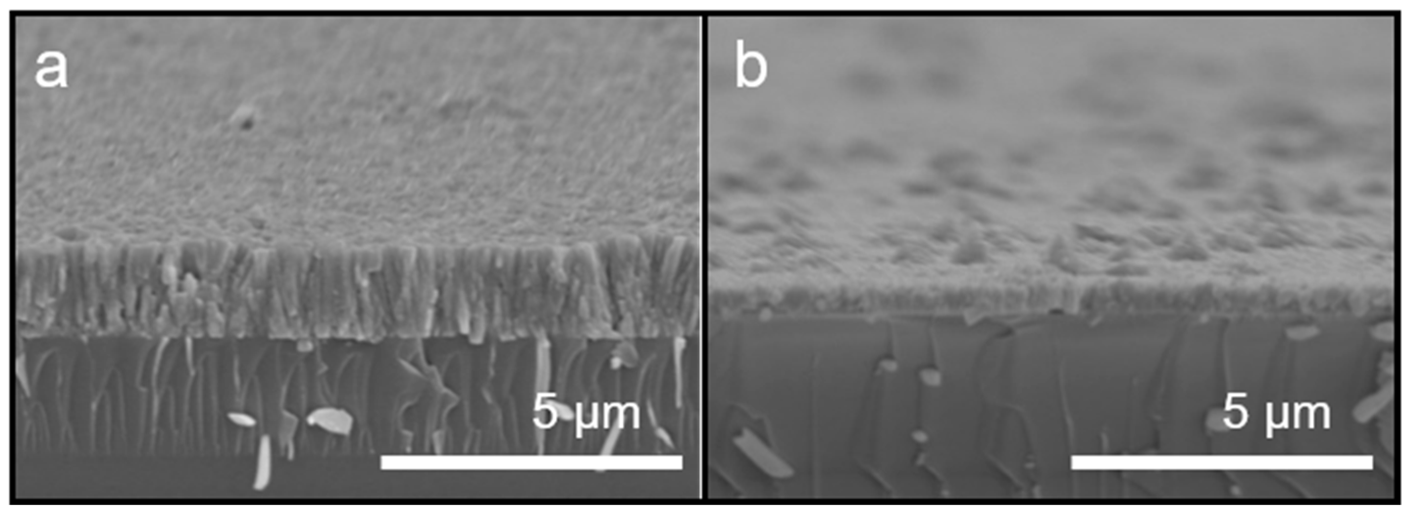
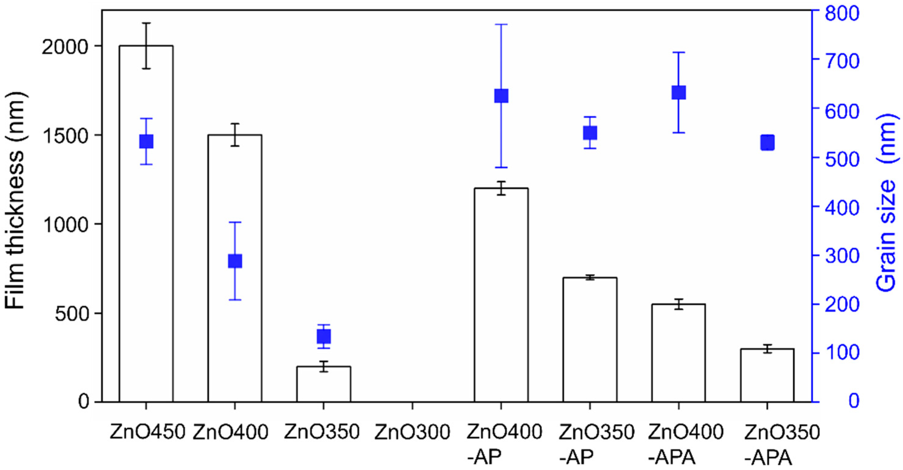
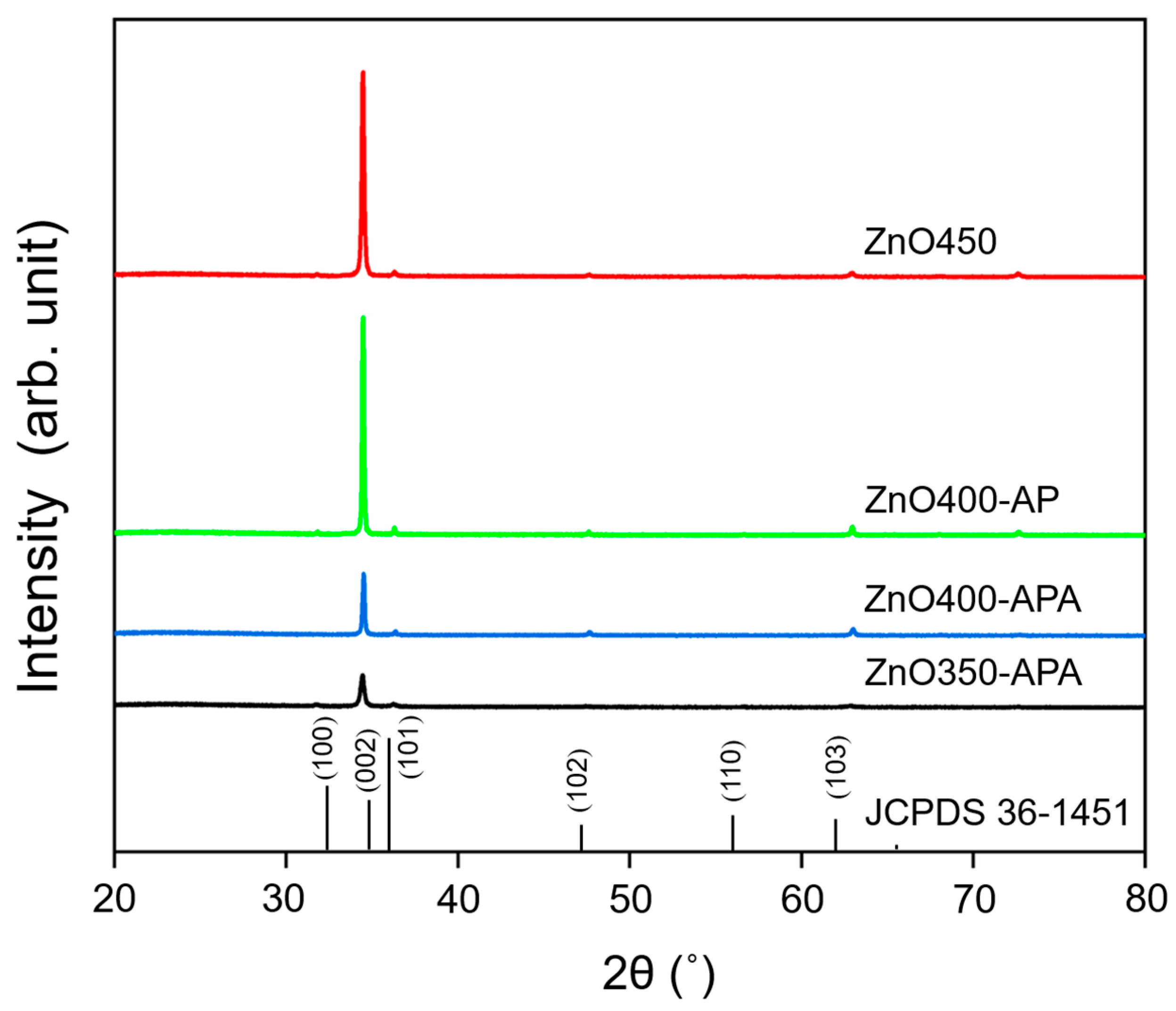
3.1. Preparation and Analysis of ZnO Coating

ZnO exhibits a hexagonal-like structure with (002) preferred orientation, which results in superior conductivity [33]. Therefore, investigating the surface morphology of ZnO with spray pyrolysis is critical. The coating surface was prepared at various substrate temperatures using ZnCl2 as the precursor and through the conventional ultrasonic spray pyrolysis process (Figure 2). Crystallized particles of the hexagonal column structure were observed at temperatures above 400 °C. At process temperatures below 400 °C, only a precursor hydrolyzed flaky structure was obtained instead of ZnO crystals. As the temperature increases, the crystal transformation becomes complete.
The use of the atmospheric-plasma-assisted process resulted in a denser wurtzite structure (Figure 3a,b) than that at the same growth temperature through conventional ultrasonic spray pyrolysis deposition. At high growth temperatures, ZnO400-AP, a dense and uniform film, was obtained. However, a reduction in the growth temperature to 350 °C resulted in a rough and less dense coating. Thus, the introduction of atmospheric plasma can increase ZnO crystallization and lower the process temperature. Figure 3c,d show the ZnO coating prepared by atmospheric microplasma-assisted ultrasonic spray pyrolysis with a substrate temperature of 400 °C and 350 °C while undergoing vacuum annealing the appearance of hexagonal columns was more apparent.
Cross-sectional SEM images of ZnO grown using atmospheric microplasma-assisted ultrasonic spray pyrolysis at 400 °C with and without vacuum annealing are shown in Figure 4. As shown in Figure 4a, the film is columnar, indicating that it grew along the C-axis and was tightly arranged, the surface of the film being relatively flat. The thickness of the film was 1.2 μm before annealing. After vacuum annealing, the thickness of the film decreased to 550 nm as the desorption of oxygen reduced its thickness, the crystals becoming more densely arranged, as shown in Figure 4b.
Figure 5 displays the thicknesses and grain sizes of ZnO under various processes. In conventional ultrasonic spray pyrolysis deposition, the higher the substrate temperature is, the thicker the coating and the larger the grain size. Thus, the higher the substrate temperature is, the more precursor is dissociated, which indicates that the temperature considerably affects the growth rate of ZnO. The coating thickness of ZnO400-AP decreased marginally because although AP contributed to the release of the precursor to increase ZnO crystallization, a high flow rate of Ar used in AP resulted in the dissociated precursor blowing away from the substrate, which reduced the reactants in the reaction area. In conventional ultrasonic spray pyrolysis deposition, the higher the temperature of the substrate is, the greater the grain size of ZnO is. For ZnO300, because the substrate temperature was not sufficiently high, only flaky zinc hydroxide chloride was observed instead of the ZnO crystal (Figure 2d) [5]. The use of AP and annealing processes had a limited effect on the size of ZnO. Thus, the introduction of AP increased the dissociation rate of the reactant, and annealing was performed for surface modification without affecting the grain size.
Figure 6 compares the crystal structures of ZnO under different processes—that is, under four different process conditions, the ZnO (200) (2θ = 34°) structure is evident, indicating that the crystals tended to grow in the C-axis direction. After vacuum annealing, the direction of the (002) crystal plane decreased significantly. This was as a result of the desorption of oxygen; a result consistent with those reported in [34]. The above study also showed that under vacuum annealing, the microcrystalline structure tended to grow in the (100) direction using plane thermal diffusion instead of the (002) direction owing to the lower surface free energy in the (100) (2θ = 31°) direction [35].

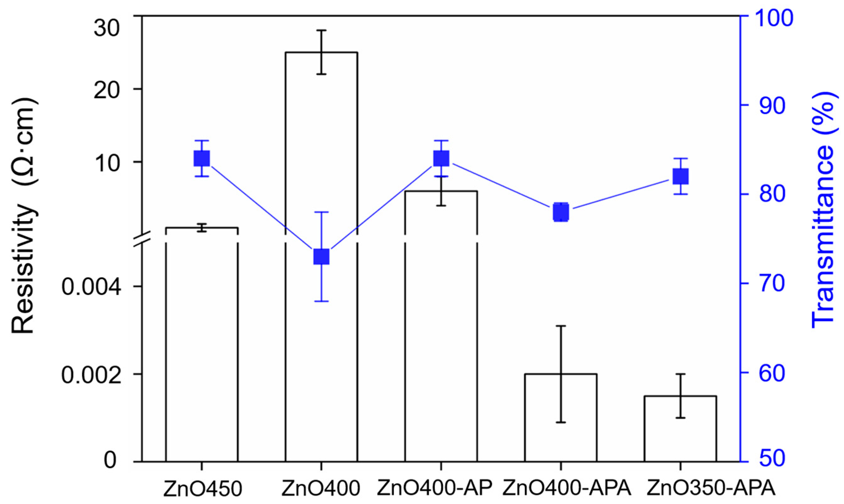
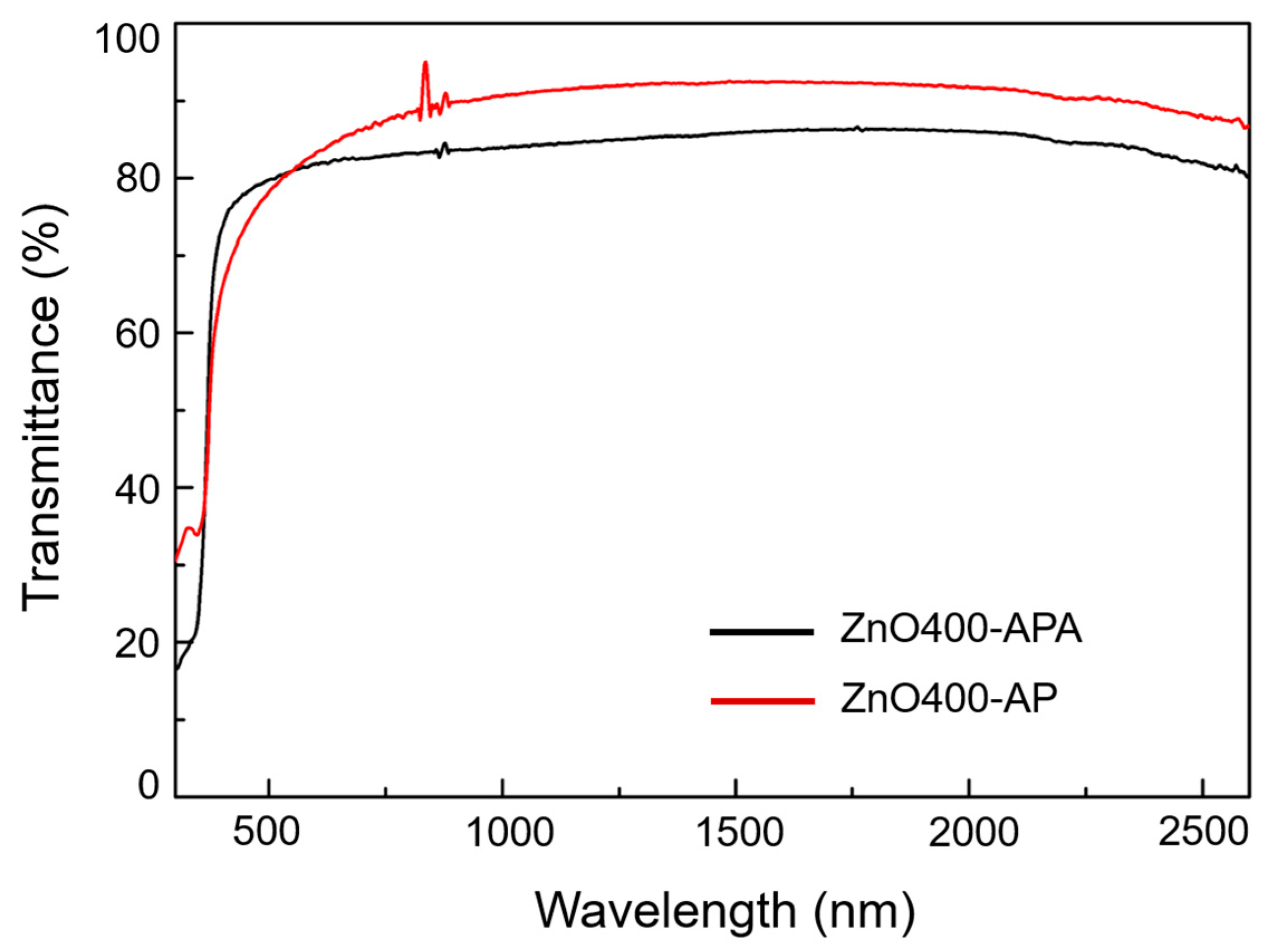
3.2. Analysis of Electrical Characteristics and Optical Behavior of ZnO Coating

The resistivity and transmittance of ZnO are shown in Figure 7. Conventional ultrasonic spray pyrolysis resistivities, such as ZnO450 and ZnO400, were 1 and 25 Ω·cm, respectively. This shows that preparation temperature played a crucial role in film formation, the results of which are shown in Figure 2a,b. A comparison of the resistivity and transmittance of ZnO400 and ZnO400-AP demonstrated that at the same process temperature, the atmospheric microplasma could effectively enhance the characteristics of ZnO, because when the droplets came in contact with the plasma, an oxidation-reduction reaction occurred at the interface, therefore increasing the efficiency of the precursor reaction [36].
The resistance of ZnO400-APA decreased by nearly five orders of magnitude relative to ZnO400-AP, owing to the effect of heat on electron hole-pair and oxygen desorption, resulting in oxygen voids forming free electrons and reducing resistivity [37]. Furthermore, lower resistivities, such as ZnO400-APA (1 × 10⁻³ Ω·cm) and ZnO350-APA (1 × 10⁻³ Ω·cm), were also obtained. As the film thickness of ZnO350-APA was lower than that of ZnO400-APA, a better transmittance of 82% was obtained.
As free carriers absorb infrared (IR) light, when the concentration of free carriers increases, more infrared light can be absorbed. Consequently, the IR absorption method can be used for inspection [38].
In Figure 8, we compared the absorption analysis of free carriers in the IR band of ZnO films with and without annealing. The oxygen vacancy defects increased, resulting in free carriers owing to oxygen atom desorption after vacuum annealing. Figure 7 shows that as the concentration increases, the absorption is more robust in the IR band; therefore, the IR band’s penetration rate is lower than that of the film without vacuum annealing, a result that is consistent with the theory proposed by Serier [38].

3.3. Tribology Behavior of ZnO

In TCO applications where mechanical stress is loaded on the coating, such as the touch of a finger, the mechanical and tribological behaviors are crucial as they affect the performance and lifespan of the coating. ZnO coatings’ tribological behavior and excellent anti-wear properties could be achieved by controlling the preparation conditions [39]. A comparison of the tribology characteristics of ZnO450 and ZnO400 demonstrates that in high-temperature synthesis, the appearance of hexagonal crystal columns is more noticeable (Figure 2 and Figure 5). Consequently, when loading was applied to the coating, load capacity improved, therefore providing better anti-wear properties as illustrated in Figure 9. A comparison of ZnO400 and ZnO400-AP demonstrated that the higher wear resistance of a complete coating on the surface helped atmospheric microplasma improve the coating quality. The surface of the ZnO coating with the AP process was relatively complete and robust. Consequently, it could provide better load capacity during friction. Moreover, improved film formation and structure could improve wear resistance. A comparison of the friction coefficients of all groups of ZnO during friction—except ZnO400—showed that they were all between 0.3 and 0.4, indicating that the friction mechanism of ZnO was identical when abrasion occurred. The reason for these slight drops was likely due to differences in the surface roughness during annealing.

4. Conclusions

This study integrated the AP system with the conventional ultrasonic spray pyrolysis deposition process to obtain a novel large-area spray-synthesis ZnO device. The effect of the process parameters of the new equipment on ZnO growth was demonstrated. The parameters include the substrate temperature, the AP system, and the subsequent annealing process. The following conclusions were drawn based on the findings of this study:
  • The atmospheric microplasma process helped to lower the synthesis temperature of ZnO.
  • The vacuum annealing process improved the electrical properties and transmittance of the ZnO coating and was a dominant factor.
  • The wear characteristics could also be used to evaluate the quality of ZnO, a good crystal structure indicating that a suitable photoelectric property naturally had good mechanical properties.
  • This study demonstrated a low-temperature, low-cost, large-area, and qualified ZnO synthesis system integrated with a program-controlled atmospheric microplasma-assisted ultrasonic spray pyrolysis system with a vacuum annealing process.
However, this study did not investigate the results of all process parameters. Subsequent studies for optimizing process parameters should focus on reducing the gas flow rate of the AP system to maximize the coating thickness.

Author Contributions

Conceptualization, S.-C.S.; methodology, S.-C.S. and J.H.-C.Y.; validation, S.-C.S.; formal analysis, S.-C.S. and P.-W.H.; investigation, P.-W.H.; resources, S.-C.S.; data curation, P.-W.H.; writing—original draft preparation, P.-W.H.; writing—review and editing, S.-C.S.; supervision, S.-C.S.; project administration, S.-C.S.; funding acquisition, S.-C.S. All authors have read and agreed to the published version of the manuscript.

Funding

The authors gratefully acknowledge the financial support for this project from the Ministry of Science and Technology in Taiwan (MOST 110-2221-E-006-150).

Institutional Review Board Statement

Not applicable.

Informed Consent Statement

Not applicable.

Data Availability Statement

Not applicable.

Acknowledgments

The authors gratefully acknowledge the use of EM000700 of MOST 110-2731-M-006-001 belonging to the Core Facility Center of National Cheng Kung University (NCKU).

Conflicts of Interest

The authors declare no conflict of interest.

References

  1. Cheng, Y.-C.; Wang, H.-C.; Lai, H.-C.; Shi, S.-C.; Chen, C.-C.; Yao, Y.-F.; Yang, C.-C. Wide range variation of resonance wavelength of gazno plasmonic metamaterials grown by molecular beam epitaxy with slight modification of zn effusion cell temperatures. J. Alloys Compd. 2021, 870, 159434. [Google Scholar] [CrossRef]
  2. Chiang, T.-C.; Chiu, C.-Y.; Dai, T.-F.; Hung, Y.-J.; Hsu, H.-C. Surface-plasmon-enhanced band-edge emission and lasing behaviors of au-decorated zno microstructures. Opt. Mater. Express 2017, 7, 313–319. [Google Scholar] [CrossRef]
  3. Chan, S.-Y.; Wu, S.-C.; Wang, C.-Y.; Hsu, H.-C. Enhanced ultraviolet electroluminescence from zno nanoparticles via decoration of partially oxidized al layer. Opt. Express 2020, 28, 2799–2808. [Google Scholar] [CrossRef] [PubMed]
  4. Lee, C.-C.; Wan, T.-H.; Hsu, C.-C.; Cheng, I.-C.; Chen, J.-Z. Atmospheric-pressure plasma jet processed pt/zno composites and its application as counter-electrodes for dye-sensitized solar cells. Appl. Surf. Sci. 2018, 436, 690–696. [Google Scholar] [CrossRef]
  5. Hsu, C.; Lien, S.; Yang, Y.; Chen, J.Z.; Cheng, I.-C.; Hsu, C. Deposition of transparent and conductive zno films by an atmospheric pressure plasma-jet-assisted process. Thin Solid Film. 2014, 570, 423–428. [Google Scholar] [CrossRef]
  6. Illiberi, A.; Poodt, P.; Bolt, P.-J.; Roozeboom, F. Recent advances in atmospheric vapor-phase deposition of transparent and conductive zinc oxide. Chem. Vap. Depos. 2014, 20, 234–242. [Google Scholar] [CrossRef]
  7. Baedeker, K. Über eine eigentümliche form elektrischen leitvermögens bei festen körpern. Ann. Phys. 1909, 334, 566–584. [Google Scholar] [CrossRef]
  8. Rupprecht, G. Untersuchungen der elektrischen und lichtelektrischen leitfähigkeit dünner indiumoxydschichten. Z. Für Phys. 1954, 139, 504–517. [Google Scholar] [CrossRef]
  9. van Boort, H.; Groth, R. Philips tech. REV 1968, 29, 13. [Google Scholar]
  10. Johnson, K.W.; Guruvenket, S.; Sailer, R.A.; Ahrenkiel, S.P.; Schulz, D.L. Atmospheric pressure plasma enhanced chemical vapor deposition of zinc oxide and aluminum zinc oxide. Thin Solid Film. 2013, 548, 210–219. [Google Scholar] [CrossRef]
  11. Favaro, M.; Zanazzi, E.; Patelli, A.; Carturan, S.; Ceccato, R.; Mulloni, V.; Bortolotti, M.; Quaranta, A. Aluminum doped zinc oxide coatings at low temperature by atmospheric pressure plasma jet. Thin Solid Film. 2020, 708, 138118. [Google Scholar] [CrossRef]
  12. Chen, Y.-Y.; Juang, J.-Y. Enhancement of ga-doped zinc oxide film properties and deposition rate by multiple deposition using atmosphere pressure plasma jet. J. Alloys Compd. 2017, 694, 452–458. [Google Scholar] [CrossRef]
  13. Barankin, M.; Ii, E.G.; Ladwig, A.; Hicks, R. Plasma-enhanced chemical vapor deposition of zinc oxide at atmospheric pressure and low temperature. Sol. Energy Mater. Sol. Cells 2007, 91, 924–930. [Google Scholar] [CrossRef]
  14. Kurtaran, S. Al doped zno thin films obtained by spray pyrolysis technique: Influence of different annealing time. Opt. Mater. 2021, 114, 110908. [Google Scholar] [CrossRef]
  15. Alam, M.; Cameron, D. Optical and electrical properties of transparent conductive ito thin films deposited by sol–gel process. Thin Solid Film. 2000, 377, 455–459. [Google Scholar] [CrossRef]
  16. Viguie, J.C.; Spitz, J. Chemical vapor deposition at low temperatures. J. Electrochem. Soc. 1975, 122, 585–588. [Google Scholar] [CrossRef]
  17. Siefert, W. Properties of thin in2o3 and sno2 films prepared by corona spray pyrolysis, and a discussion of the spray pyrolysis process. Thin Solid Film. 1984, 120, 275–282. [Google Scholar] [CrossRef]
  18. Tendero, C.; Tixier, C.; Tristant, P.; Desmaison, J.; Leprince, P. Atmospheric pressure plasmas: A review. Spectrochim. Acta Part B At. Spectrosc. 2006, 61, 2–30. [Google Scholar] [CrossRef]
  19. Bornholdt, S.; Wolter, M.; Kersten, H. Characterization of an atmospheric pressure plasma jet for surface modification and thin film deposition. Eur. Phys. J. D 2010, 60, 653–660. [Google Scholar] [CrossRef]
  20. Brunet, P.; Rincón, R.; Margot, J.; Massines, F.; Chaker, M. Deposition of homogeneous carbon-tio2 composites by atmospheric pressure dbd. Plasma Process. Polym. 2017, 14, 1600075. [Google Scholar] [CrossRef]
  21. Hsu, Y.-W.; Li, H.-C.; Yang, Y.-J.; Hsu, C.-C. Deposition of zinc oxide thin films by an atmospheric pressure plasma jet. Thin Solid Film. 2011, 519, 3095–3099. [Google Scholar] [CrossRef]
  22. Chang, K.-M.; Huang, S.-H.; Wu, C.-J.; Lin, W.-L.; Chen, W.-C.; Chi, C.-W.; Lin, J.-W.; Chang, C.-C. Transparent conductive indium-doped zinc oxide films prepared by atmospheric pressure plasma jet. Thin Solid Film. 2011, 519, 5114–5117. [Google Scholar] [CrossRef]
  23. Shi, S.-C.; Wang, C.-C.; Cheng, Y.-C.; Lin, Y.-F. Surface characterization and tribological behavior of graphene-reinforced cellulose composites prepared by large-area spray coating on flexible substrate. Coatings 2020, 10, 1176. [Google Scholar] [CrossRef]
  24. Shi, S.-C.; Chen, T.-H.; Mandal, P.K. Enhancing the mechanical and tribological properties of cellulose nanocomposites with aluminum nanoadditives. Polymers 2020, 12, 1246. [Google Scholar] [CrossRef] [PubMed]
  25. Shi, S.-C.; Jiang, S.-Z. Influence of graphene/copper hybrid nanoparticle additives on tribological properties of solid cellulose lubricants. Surf. Coat. Technol. 2020, 389, 125655. [Google Scholar] [CrossRef]
  26. Shi, S.-C.; Tsai, X.-N.; Pek, S.-S. Tribological behavior and energy dissipation of hybrid nanoparticle-reinforced hpmc composites during sliding wear. Surf. Coat. Technol. 2020, 389, 125617. [Google Scholar] [CrossRef]
  27. Shi, S.-C.; Peng, Y.-Q. Preparation and tribological studies of stearic acid-modified biopolymer coating. Prog. Org. Coat. 2020, 138, 105304. [Google Scholar] [CrossRef]
  28. Shi, S.-C.; Pek, S.-S. Third-body and dissipation energy in green tribology film. Appl. Sci.-Basel 2019, 9, 3787. [Google Scholar] [CrossRef] [Green Version]
  29. Shi, S.-C.; Wu, J.-Y.; Peng, Y.-Q. Transfer layer formation in mos2/hydroxypropyl methylcellulose composite. Wear 2018, 408, 208–213. [Google Scholar] [CrossRef]
  30. Jayatissa, A.H.; Ahmed, O.; Manu, B.R.; Schroeder, A.M. Tribological behaviour of sputter coated zno thin films. Prog. Mater. Sci. 2021, 3, 1–13. [Google Scholar]
  31. Singh, Y.; Singh, N.K.; Sharma, A.; Singla, A.; Singh, D.; Rahim, E.A. Effect of zno nanoparticles concentration as additives to the epoxidized euphorbia lathyris oil and their tribological characterization. Fuel 2021, 285, 119148. [Google Scholar] [CrossRef]
  32. Ren, B.; Gao, L.; Li, M.; Zhang, S.; Ran, X. Tribological properties and anti-wear mechanism of zno@ graphene core-shell nanoparticles as lubricant additives. Tribol. Int. 2020, 144, 106114. [Google Scholar] [CrossRef]
  33. Bacaksiz, E.; Parlak, M.; Tomakin, M.; Özçelik, A.; Karakız, M.; Altunbaş, M. The effects of zinc nitrate, zinc acetate and zinc chloride precursors on investigation of structural and optical properties of zno thin films. J. Alloys Compd. 2008, 466, 447–450. [Google Scholar] [CrossRef]
  34. Lee, J.-H.; Park, B.-O. Characteristics of al-doped zno thin films obtained by ultrasonic spray pyrolysis: Effects of al doping and an annealing treatment. Mater. Sci. Eng. B 2004, 106, 242–245. [Google Scholar] [CrossRef]
  35. Kennedy, J.; Murmu, P.; Leveneur, J.; Markwitz, A.; Futter, J. Controlling preferred orientation and electrical conductivity of zinc oxide thin films by post growth annealing treatment. Appl. Surf. Sci. 2016, 367, 52–58. [Google Scholar] [CrossRef]
  36. Mariotti, D.; Patel, J.; Švrček, V.; Maguire, P. Plasma—Liquid interactions at atmospheric pressure for nanomaterials synthesis and surface engineering. Plasma Process. Polym. 2012, 9, 1074–1085. [Google Scholar] [CrossRef]
  37. Ghosh, R.; Paul, G.; Basak, D. Effect of thermal annealing treatment on structural, electrical and optical properties of transparent sol–gel zno thin films. Mater. Res. Bull. 2005, 40, 1905–1914. [Google Scholar] [CrossRef]
  38. Serier, H.; Gaudon, M.; Ménétrier, M. Al-doped zno powdered materials: Al solubility limit and ir absorption properties. Solid State Sci. 2009, 11, 1192–1197. [Google Scholar] [CrossRef]
  39. Lin, L.-Y.; Kim, D.-E. Effect of annealing temperature on the tribological behavior of zno films prepared by sol–gel method. Thin Solid Film. 2009, 517, 1690–1700. [Google Scholar] [CrossRef]
Figure 1. Schematic of the atmospheric microplasma-assisted ultrasonic spray pyrolysis system.
Coatings 11 01001 g001
Figure 2. SEM images of ZnO coatings prepared using ultrasonic spray pyrolysis at (a) 450 °C, (b) 400 °C, (c) 350 °C, and (d) 300 °C.
Coatings 11 01001 g002
Figure 3. SEM images of ZnO coatings prepared using the atmospheric microplasma-assisted ultrasonic spray pyrolysis process at (a) 400 °C, (b) 350 °C, (c) 400 °C with vacuum annealing, and (d) 350 °C with vacuum annealing.
Coatings 11 01001 g003
Figure 4. Cross-sectional SEM images of ZnO coatings prepared using the atmospheric microplasma-assisted ultrasonic spray pyrolysis process at (a) 400 °C, and (b) 400 °C with vacuum annealing.
Coatings 11 01001 g004
Figure 5. Thickness and grain sizes of ZnO of various processing conditions.
Coatings 11 01001 g005
Figure 6. X-ray diffraction of ZnO obtained through different processes, indexed to the ZnO phase (JCPDS Card no. 36-1451). The three digits represent the preparation temperature of ultrasonic spray pyrolysis; AP stands for the atmospheric microplasma-assisted process; APA indicates ZnO prepared using the atmospheric microplasma-assisted ultrasonic spray pyrolysis process and vacuum annealing processes.
Coatings 11 01001 g006
Figure 7. Resistivity and transmittance of ZnO coatings.
Coatings 11 01001 g007
Figure 8. Comparison of transmittance of ZnO400-APA and ZnO400-AP.
Coatings 11 01001 g008
Figure 9. Wear volume and average coefficient of friction of ZnO coatings.
Coatings 11 01001 g009
Publisher’s Note: MDPI stays neutral with regard to jurisdictional claims in published maps and institutional affiliations.

