Optimization Study of Fluffy Materials Flocking Drainage Pipes to Resist Blockage Based on MD Binding Energy


Abstract
:1. Introduction
2. Methods
2.1. Molecular Dynamics Software
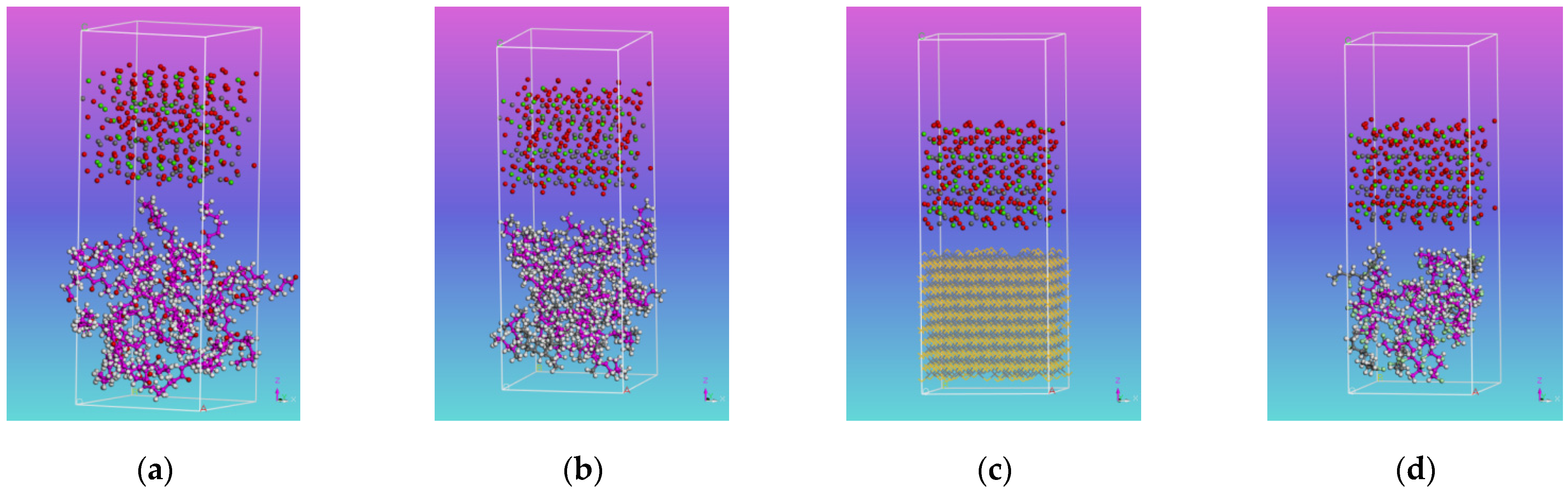
2.2. Model Building
2.3. Parameter Setting
3. Results and Discussion
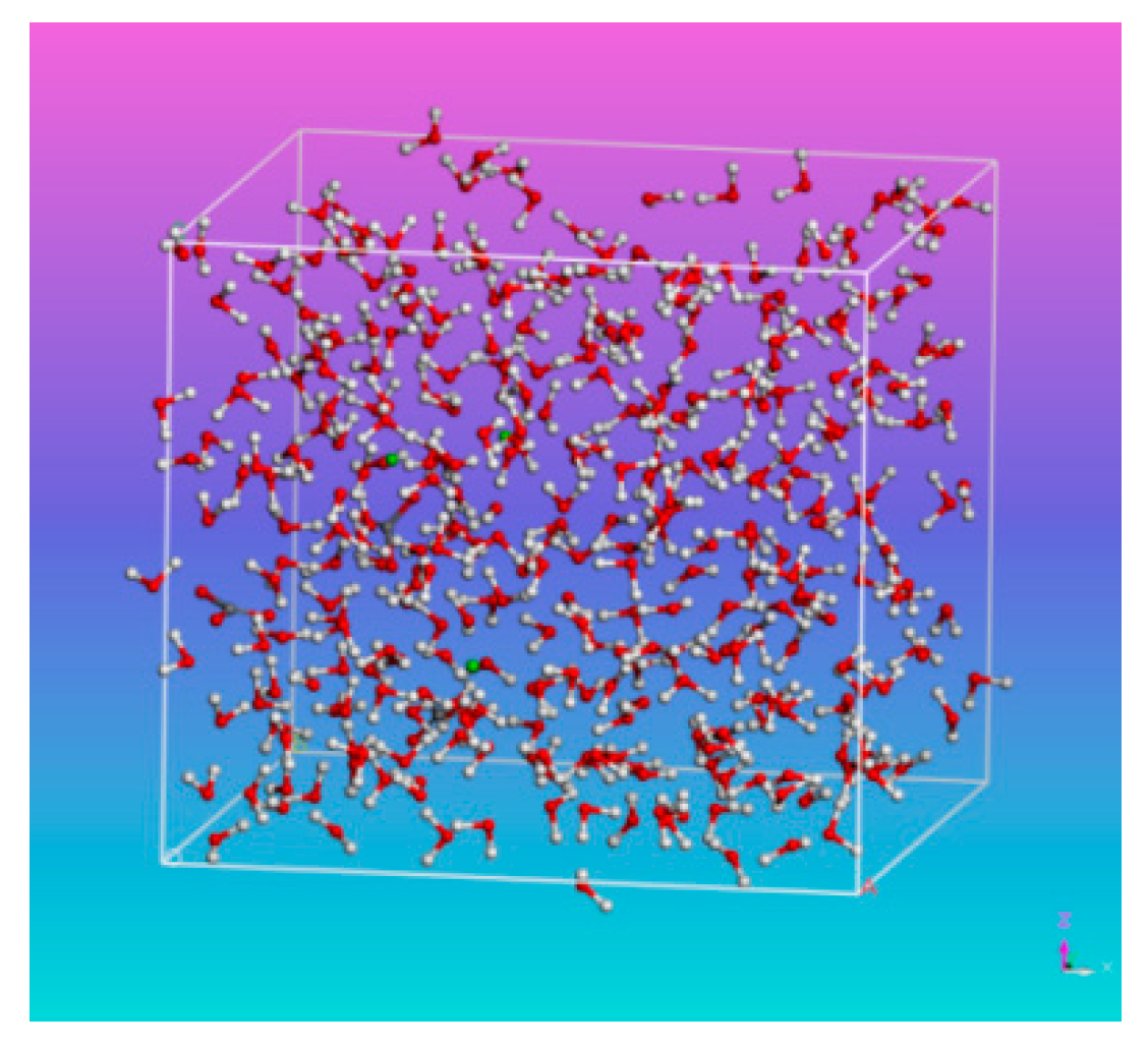
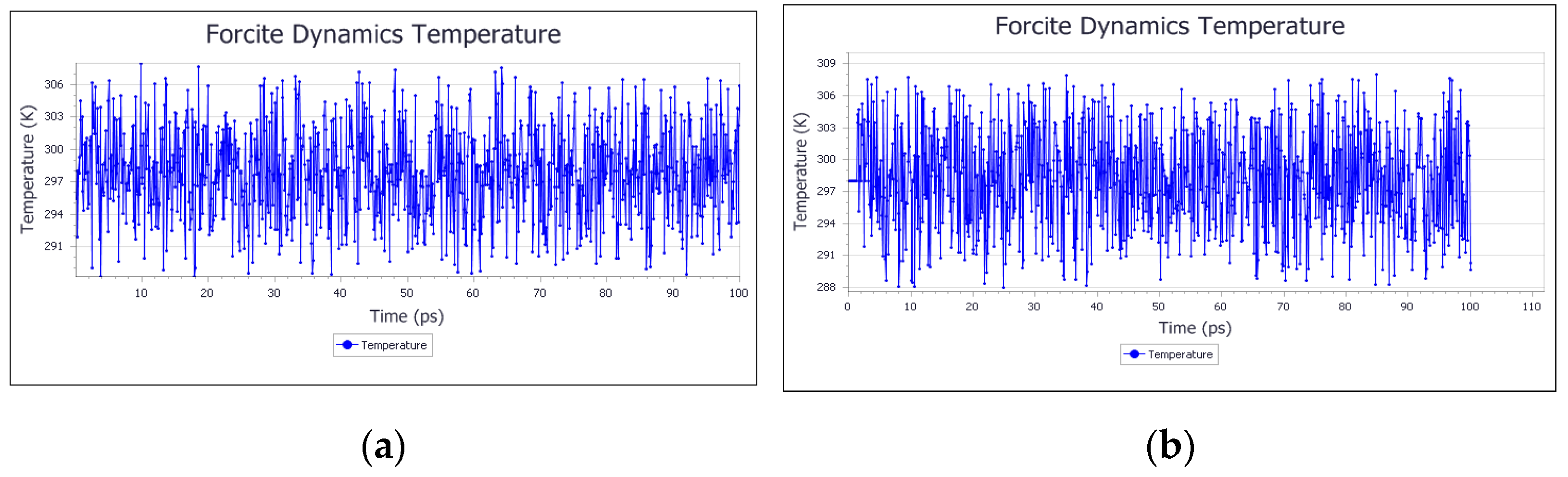
3.1. System Equilibrium
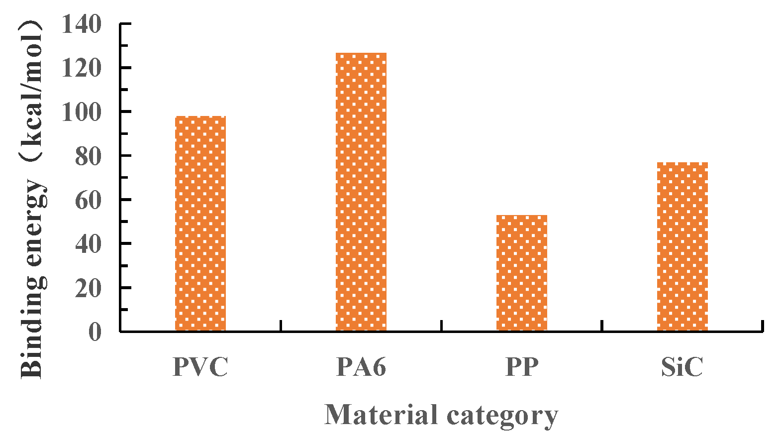
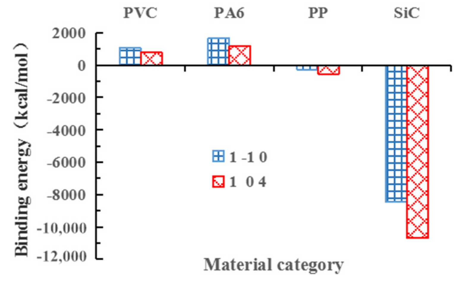
3.2. Binding Energy Analysis
4. Conclusions
- (1)
- PA6, PVC, SiC and PP all have adsorption effect on calcium carbonate solution, and the order of binding energy is PA6 > PVC > SiC > PP.
- (2)
- The results show that PVC, PA6 and CaCO3 can spontaneously adsorb on each other, while PP and SiC can only adsorb on each other with the help of external energy. The energy absorbed by (1 0 4) crystal face is greater than that absorbed by (1 −1 0) crystal face.
- (3)
- The follow-up research can start from the energy of the solution system and the crystal itself and find the technology to make the energy of the system or crystal in a low state, so that the crystal and the pipe are not combined.
- (4)
- From the point of view of anti-crystallization effect, while considering the binding energy between materials, it is also necessary to ensure the excellent geometric characteristics of pile (smooth surface and straight length direction), so as to maximize the anti-crystallization effect of flocking drainage pipe. In addition to the binding energy, the molecular weight and production process of polymer should also be considered in the follow-up study.
Author Contributions
Funding
Institutional Review Board Statement
Informed Consent Statement
Data Availability Statement
Conflicts of Interest
References
- Jiang, Y.; Du, K.; Tao, L.; Zhao, J.; Xiao, H. Investigation and discussion on blocking mechanism of drainage system in karst tunnels. Railw. Stand. Des. 2019, 63, 131–135. [Google Scholar]
- Tian, C.; Ye, F.; Song, G.; Wang, Q.; Zhao, M.; He, B.; Wang, J.; Han, X. On Mechanism of crystal blockage of tunnel drainage system and preventive countermeasures. Mod. Tunn. Technol. 2020, 57, 66–76. [Google Scholar]
- Xiang, K.; Zhou, J.; Zhang, X.; Huang, C.; Song, L.; Liu, S. Experimental study on crystallization rule of tunnel drainpipe in alkaline environment. Tunn. Constr. 2019, 39, 207–212. [Google Scholar]
- Ye, F.; Tian, C.; Zhao, M.; He, B.; Wang, J.; Han, X. The disease of scaling and cloging in the drainage pipes of a tunnel under construction in yunnan. China Civ. Eng. J. 2020, 53, 336–341. [Google Scholar]
- Zhou, Y.; Zhang, X.; Wei, L.; Liu, S.; Zhang, B.; Zhou, C. Experimental study on prevention of calcium carbonate crystallizing in drainage pipe of tunnel engineering. Adv. Civ. Eng. 2018, 2018, 1–11. [Google Scholar] [CrossRef] [Green Version]
- Jiang, Y.; Du, K.; Liao, J.; Chen, X.; Xiao, H. Experimental research on maintainability of drainage facilities in lining construction joints of karst tunnel. Railw. Stand. Des. 2019, 63, 91–96. [Google Scholar]
- Su, Y.; Yang, H.; Shi, W.; Guo, H.; Zhao, Y.; Wang, D. Crystallization and morphological control of calcium carbonate by functionalized triblock copolymers. Colloids Surf. Physicochem. Eng. Asp. 2009, 355, 158–162. [Google Scholar] [CrossRef]
- Kirboga, S.; Oner, M.; Akyol, E. The effect of ultrasonication on calcium carbonate crystallization in the presence of biopolymer. J. Cryst. Growth 2014, 401, 266–270. [Google Scholar] [CrossRef]
- Su, M.; Han, J.; Li, Y.; Chen, J.; Zhao, Y.; Chadwick, K. Ultrasonic crystallization of calcium carbonate in presence of seawater Ions. Desalination 2015, 369, 85–90. [Google Scholar] [CrossRef]
- Menzri, R.; Ghizellaoui, S.; Tlili, M. Calcium carbonate inhibition by green inhibitors: Thiamine and pyridoxine. Desalination 2017, 404, 147–154. [Google Scholar] [CrossRef]
- Hong, Y.; Qian, X.; Li, J.; Yang, H.; Zhang, P. On scavenging performances of cleaning solvents for the clogging in the drainage system of karst tunnels. Mod. Tunn. Technol. 2020, 57, 160–170. [Google Scholar]
- Liu, S.; Zhang, X.; Lü, H.; Liu, Q.; Wang, B. The effect of flocking PVC pipe on the prevention and crystallization of tunnel drains. Sci. Technol. Eng. 2018, 18, 313–319. [Google Scholar]
- Liu, S.; Zhang, X.; Lü, H.; Liu, Q.; Wang, B. The effect of anti-crystallization of tunnel plumage drain pipe under different water filling state. Sci. Technol. Eng. 2018, 18, 156–163. [Google Scholar]
- Liu, S.; Gao, F.; Zhou, Y.; Liu, Q.; Lü, H.; Wang, B.; Xiang, K.; Xiao, D. Effect of fuzz length on the prevention of crystallization of tunnel flocking drainpipes. Sci. Technol. Eng. 2019, 19, 234–239. [Google Scholar]
- Liu, S.; Gao, F.; Zhang, X.; Han, F.; Zhou, Y.; Xiang, K.; Xiao, D. Experimental study on anti-crystallization law of tunnel transverse flocking drainpipe at different velocities. Asia-Pac. J. Chem. Eng. 2020, 15, 1–9. [Google Scholar] [CrossRef]
- Liu, S.; Zhang, X.; Gao, F.; Wei, L.; Liu, Q.; Lü, H.; Wang, B. Two-dimensional flow field distribution characteristics of flocking drainage pipes in tunnel. Open Phys. 2020, 18, 139–148. [Google Scholar] [CrossRef]
- Leeuw, N.H.D. Molecular dynamics simulation of the growth inhibiting effect of Fe2+, Mg2+, Cd2+,and Sr2+ on calcite crystal growth. J. Phys. Chem. B 2002, 106, 5241–5249. [Google Scholar] [CrossRef]
- Wang, D.; Huang, L.; Wei, M.; Wang, T.; Tian, Y. MD simulation of influence of high voltage static electric field on crystallization of calcium carbonate. Ind. Water Wastewater 2010, 41, 76–79. [Google Scholar]
- Hädicke, E.; Rieger, J.; Rau, I.U.; Boeckh, D. Molecular dynamics simulations of the incrustation inhibition by polymeric additives. Phys. Chem. Chem. Phys. 1999, 1, 3891–3898. [Google Scholar] [CrossRef]
- Zhao, W.; Zhang, Q.; Chen, T.; Zhang, J.; Lu, T.; Zhang, H. Molecular dynamics simulation of adsorption of polyelectrolyte on the polystyrene microspheres. J. Mater. Sci. Eng. 2009, 27, 329–331. [Google Scholar]


| Material Category | Density | Chemical Composition | Chemical Formula | Structural Formula | Schematic Diagram |
|---|---|---|---|---|---|
| M1 | 1.13 g/cm3 | PA6 | (C6H11NO)n | 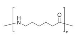 |  |
| M2 | 0.90 g/cm3 | PP | (C3H6) n |  | 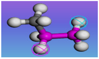 |
| M3 | 3.20 g/cm3 | SiC | SiC | 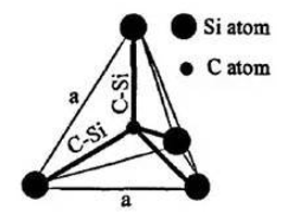 |  |
| PVC | 1.38 g/cm3 | VCM | (C2H3Cl)n | 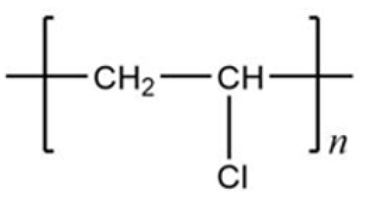 | 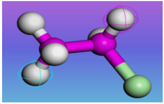 |
| Model System | Etotal | Elower | Eupper | ΔE | Ebinding | ||
|---|---|---|---|---|---|---|---|
| solid-solid | CaCO3-PVC | 1 −1 0 | −20,132.466 | −574.596 | −18,487.159 | −1070.711 | 1070.711 |
| 1 0 4 | −38,045.005 | −542.662 | −36,704.997 | −797.346 | 797.346 | ||
| CaCO3-PA6 | 1 −1 0 | −21,054.710 | −937.917 | −18,467.027 | −1649.766 | 1649.766 | |
| 1 0 4 | −38,758.331 | −928.115 | −36,671.616 | −1158.600 | 1158.600 | ||
| CaCO3-PP | 1 −1 0 | −17,540.010 | 676.839 | −18,487.308 | 270.459 | −270.459 | |
| 1 0 4 | −35,527.521 | 616.249 | −36,683.798 | 540.028 | −540.028 | ||
| CaCO3-SiC | 1 −1 0 | −117,279.169 | −107,275.987 | −18,473.126 | 8469.944 | −8469.944 | |
| 1 0 4 | −133,290.641 | −107,264.983 | −36,691.537 | 10,665.879 | −10,665.879 | ||
| solid-liquid | Solution-PVC | −4703.853 | −577.787 | −4028.226 | −97.840 | 97.840 | |
| Solution-PA6 | −3849.500 | 269.641 | −3992.464 | −126.677 | 126.677 | ||
| Solution-PP | −3470.688 | 625.414 | −4043.291 | −52.811 | 52.811 | ||
| Solution-SiC | −111,111.148 | −107,276.559 | −3757.73 | −76.859 | 76.859 | ||
Publisher’s Note: MDPI stays neutral with regard to jurisdictional claims in published maps and institutional affiliations. |
© 2021 by the authors. Licensee MDPI, Basel, Switzerland. This article is an open access article distributed under the terms and conditions of the Creative Commons Attribution (CC BY) license (https://creativecommons.org/licenses/by/4.0/).
Share and Cite
Liu, S.; Zhang, X.; Zhou, Y.; Gao, F. Optimization Study of Fluffy Materials Flocking Drainage Pipes to Resist Blockage Based on MD Binding Energy. Coatings 2021, 11, 853. https://doi.org/10.3390/coatings11070853
Liu S, Zhang X, Zhou Y, Gao F. Optimization Study of Fluffy Materials Flocking Drainage Pipes to Resist Blockage Based on MD Binding Energy. Coatings. 2021; 11(7):853. https://doi.org/10.3390/coatings11070853
Chicago/Turabian StyleLiu, Shiyang, Xuefu Zhang, Yuanfu Zhou, and Feng Gao. 2021. "Optimization Study of Fluffy Materials Flocking Drainage Pipes to Resist Blockage Based on MD Binding Energy" Coatings 11, no. 7: 853. https://doi.org/10.3390/coatings11070853
APA StyleLiu, S., Zhang, X., Zhou, Y., & Gao, F. (2021). Optimization Study of Fluffy Materials Flocking Drainage Pipes to Resist Blockage Based on MD Binding Energy. Coatings, 11(7), 853. https://doi.org/10.3390/coatings11070853