Article

Analysis of Different Complex Multilayer PACVD Coatings on Nanostructured WC-Co Cemented Carbide

1
Faculty of Mechanical Engineering and Naval Architecture, University of Zagreb, Ivana Lučića 5, 10000 Zagreb, Croatia
2
Department of Polytechnics, University of Rijeka, Sveučilišna Avenija 4, 51000 Rijeka, Croatia
*
Author to whom correspondence should be addressed.
Coatings 2021, 11(7), 823; https://doi.org/10.3390/coatings11070823
Submission received: 28 May 2021 / Revised: 2 July 2021 / Accepted: 4 July 2021 / Published: 8 July 2021
(This article belongs to the Special Issue Recent Advances in Thin Films Deposited by Vacuum Methods)

Abstract

:
The development of cemented carbides nowadays is aimed at the application and sintering of ultrafine and nano-sized powders for the production of a variety of components where excellent mechanical properties and high wear resistance are required for use in high temperature and corrosive environment conditions. The most efficient way of increasing the tribological properties along with achieving high corrosion resistance is coating. Using surface processes (modification and/or coating), it is possible to form a surface layer/base material system with properties that can meet modern expectations with acceptable production costs. Three coating systems were developed on WC cemented carbides substrate with the addition of 10 wt.% Co using the plasma-assisted chemical vapor deposition (PACVD) method: single-layer TiN coating, harder multilayer gradient TiCN coating composed of TiN and TiCN layers, and the hardest multilayer TiBN coating composed of TiN and TiB2. Physical and mechanical properties of coated and uncoated samples were investigated by means of quantitative depth profile (QDP) analysis, nanoindentation, surface layer characterization (XRD analysis), and coating adhesion evaluation using the scratch test. The results confirm the possibility of obtaining nanostructured cemented carbides of homogeneous structure without structural defects such as eta phase or unbound carbon providing increase in hardness and fracture toughness. The lowest adhesion was detected for the single-layer TiN coating, while coatings with a complex architecture (TiCN, TiBN) showed improved adhesion.

1. Introduction

Cemented carbides’ application range is constantly expanding thanks to their superior properties: good abrasion resistance, high flexural and compressive strength, high modulus of elasticity, good thermal resistance, high corrosion resistance, and so on. Different surface coating methods have been studied as means of additional modification of their properties mostly in the direction of enhanced wear and corrosion behavior. Studies have shown coatings of titanium nitride (TiN) [1], titanium carbide (TiC) [2], titanium carbonitride (TiCN) [3], titanium boron nitride (TiBN) [4], and titanium aluminum nitride (TiAlN) [5] can provide significant improvements to the cemented carbides’ behavior in exploitation of the wide range of applications, such as cutting tools [6,7], biomedical implants [8,9,10], and jet nozzles [11,12]. These coatings are mostly deposited using one of three techniques: chemical vapor deposition (CVD), physical vapor deposition (PVD), and plasma-assisted chemical vapor deposition (PACVD) process [13]. A commonly used coating method, the CVD method, conducted at high temperatures in the range of 700–1100 °C, has been shown to result in eta (η)-phase formation in the form of metal carbides (M6C, M12C) in the diffusion zone between the coating and the carbide substrate, as shown in many studies [14]. This eta phase occurrence has been linked to degradation of cemented carbides’ mechanical properties and poor adhesion between the coating and the substrate [15,16]. In some applications where high loads are not present and wear resistance is crucial demand, such as nozzles, controlled induction of the eta phase has been shown to have a beneficial effect on the cemented carbide wear behavior [17].
Alternative CVD technologies that take place at lower temperatures are thus explored—the first being PVD, with deposition temperatures usually under 500 °C. Nevertheless, PVD coating uses lower pressures, making substrate rotation crucial for obtaining a uniform coating [18]. One of the most modern surface engineering technologies, plasma-assisted coating from the vapor phase (abbreviated PACVD), enables deposition of uniform complex coating systems on different cemented carbides at significantly lower temperatures. So far, PACVD coating was mostly studied as a method of multilayer coating deposition, where good coating properties and high deposition rates were possible even for substrates of complex geometry [19,20]. Studies of Ti (C, N) coatings deposited via the PACVD method indicate process temperature, plasma power, duty cycle, and CH4/TiCl4 flow rates to be key parameters governing deposition [21,22,23]. Kim et al. [24], like many other studies [25,26,27], investigated and compared hardness, wear resistance, and nano-mechanical properties of different single and multilayer (TiN/TiC) coatings on different substrates.
The use of nano-sized cemented carbides has been shown to result in relatively high flexural strength and fracture toughness and high hardness values, thus contributing to the crack propagation resistance [28]. However, all these properties are dependent on nano-scale structure and its preservation during sintering and coating at lower temperatures, such as those of the PACVD process. Undesirable grain growth can be reduced by adding grain growth inhibitors (GGIs) such as carbides of vanadium, chromium, tantalum, and niobium, and with optimal time–temperature process setting. The combination of VC-Cr3C2 (TaC) has been shown to result in an optimal ratio of hardness and fracture toughness [29]. Recent studies have focused on the development of multilayer and gradient type coatings [30,31,32]. These multilayer coatings can generally be divided into three functional layers. These include the bottom layer, whose main function is establishing coating/substrate adhesion; the middle layer, which gradually transforms from the bottom to top layer, creating a bond between the layers; and the hard top layer.
Research on the comparison of different multilayer complex coatings deposited on nanostructured cemented carbides by PACVD method is scarce. This paper describes the development of nanostructured cemented carbides through advanced sinter HIP consolidation processes, which significantly improves the mechanical, tribological, and thermal properties of the examined material while maintaining nano-scale substrate structure. An advanced surface engineering technique was utilized to improve the properties of the carbide substrate, primarily in terms of its mechanical and adhesion behavior. A combination of nano-sized cemented carbides and complex TiN, TiCN, and TiBN coatings by means of the PACVD process was investigated. The advantage of PACVD technology is the combination of the positive aspects of CVD as a simple coating process and PVD as a low temperature deposition process. In this study, it was used on nanostructured cemented carbide substrates in a way that avoids both the formation of unwanted eta-phase, which occurs at temperatures above 550 °C, and the need to rotate the sample characteristic of PVD. The proposed coating procedure simplifies and reduces the cost of the coating process, bringing coated nano WC-Co carbides closer to a wide range of applications for industrial production.

2. Materials and Methods

2.1. Cemented Carbides’ Substrate Sintering

Through the application of the sinter-HIP process, samples of nanostructured cemented carbide were consolidated while using mixtures of nano powder of tungsten carbide, WC (grain size: 0.095 µm; specific surface: 3.92 m2/g), manufacturer: H.C. Starck, Goslar, Germany; and cobalt powder, Co (grain size: 0.640 µm; specific surface: 2.96 m2/g), manufacturer: Umicore, Markham, ON, Canada. Co content of 10 wt.% was chosen for all samples with the addition of 0.5 wt.% vanadium carbide (VC) and 0.75 wt.% chromium carbide (Cr2C3) as grain growth inhibitors (GGIs). After dry mixing and milling of WC and Co powders in a horizontal ball mill (Netzsch FMT, Selb, Germany), 2 wt.% of plasticizers in the form of paraffin was added to the powder mixture to assure good formability of the raw material during the compaction process. Sieving was carried out for the purpose of acquiring the desired powder flow properties. An FCT Anlagenbau GmbH furnace, type: FPW 280/600-3-2200-100-PS (Caloric Anlagenbau GmbH, Sonneberg, Germany) was used for both the pre-sintering and sintering phases. To establish the complete elimination of the binder phase prior to sintering, sample weight was determined. To avoid the eta phase and unbound carbon occurrence, the grain growth inhibitors and carbon content were adjusted accordingly during sintering.
Pre-sintering included the following stages: heating with a rate of 1 K/min in H2 up to 400 °C, holding at 400 °C for 60 min in the Ar atmosphere, heating with rate of 5 K/min in Ar up to 800 °C, holding at 800 °C for 60 min, and cooling to the room temperature. The sinter-HIP processing was used for sample sintering. Two-stage sintering was conducted with vacuum sintering at 1350 °C, with a 5 K/min heating rate up to 1200 °C, a 10 K/min heating rate from 1200 to 1350 °C, holding at 1350 °C for 30 min, followed by single-cycle hot isostatic pressing at 1350 °C at 100 bar Ar pressure for 45 min. An atmosphere of inert gas was applied to minimize any structural changes due to the external atmosphere. A detailed description of the sinter-HIP process implementation is given in [33].

2.2. Coating

Prior to coating, the surface of the substrates was treated to achieve satisfactory coating adhesion and preparation for the following coating analysis. The sample surface was metallographically prepared and finally polished in accordance with the recommendations for that type of material (see Supplementary Materials Table S1), which was necessary for following characterization including microhardness, thickness, and roughness testing, as well as Rockwell adhesion test and scratch test.
The samples were also ultrasonically treated by immersion in a bath of 99.8% isopropyl alcohol for 5 min and dried.
Considering the desired coatings’ architecture, the composition, and structure, three coating types were defined: TiN, TiN-TiCN (labeled TiCN), and TiN-TiB2 (labeled TiBN), as shown in Table 1. For each type of coating, five samples were produced.
The coating process was carried out in a PACVD system, type PC 70/90 (Rübig GmbH & Co KG, Marchtrenk, Austria). Regardless of the complex coating type, TiN layer is present as a bottom layer on all coated samples, whose main function was to reduce residual stresses due to different heat dilatation of substrate and coating. Studies have shown that a smaller difference in the coefficient of thermal expansion between the TiN coating (TiN = 9.4 × 10⁻⁶ °C−1, TiCN = 8 × 10⁻⁶ °C−1) and the substrate material, along with increased toughness of layers, gives TiN multilayer coatings the potential of reducing residual stresses by 50% [34].

2.2.1. TiN Coating

During the TiN coating process, the process parameters described were controlled, namely, temperature, gas flow, voltage, plasma power, pulsation time, and pressure (see Supplementary Materials Figure S1 and Table S2). Pure gases of quality 5.0 were used in the coating: H2, Ar, N2, and the precursor TiCl4. Prior to coating, the samples were treated with ion dusting for 2.5 h at a temperature of 490 to 530 °C. During the ionic cleaning process, the voltage difference between the anode and the cathode was controlled, with ion particles hitting the surface at high speed, and thus cleaning the sample and initiating activation processes on the surface. The cleaning was carried out in a standard mixture of gases 13% N2, 4% Ar, and 83% H2 with a voltage of 540 V and a plasma power of 900 to 1800 W at a pressure of 2 bar. This was followed by the application of TiN coating for 6 h at 530 °C. After coating, the samples were cooled to room temperature with a hydrogen flow rate of 100 L/h for 1.5 h.

2.2.2. TiCN Coating

During the TiCN coating process, the same parameters were controlled as in the TiN deposition process (temperature, gas flow, voltage, plasma power, pulsation time, and pressure), with super pure CH4 (quality 5.0) being used in addition to H2, Ar, N2, and TiCl4 as a precursor (see Supplementary Materials Table S3). Prior to coating, ionic dusting was also performed with the same parameters as TiN coating. An innovative complex TiCN coating was deposited consisted of a thin supporting layer of TiN followed by a layer of TiCN, and then these layers were alternately arranged one after the other, with the final layer being TiCN (see Supplementary Materials Figure S2). Twenty alterations of TiN/TiCN were made with the aim of increasing the hardness and reducing the residual stresses in the coating as well as increasing the adhesion between the layers. The deposition temperature of the coating process was 530 °C. The transition from TiN to TiCN layer was achieved by reducing the N2 content and introducing CH4.

2.2.3. TiBN Coating

Prior to coating, the samples were cleaned by the ionic technique, as done for the previous two types of coatings. The deposition of a coating of complex architecture built of TiN and TiB2 layers was carried out on five samples with the parameters shown in Supplementary Materials Table S4.
The coating on this surface was expected to exhibit better adhesion, and thus better exploitation properties. A complex architecture built of TiN and TiB2 layers was deposited on samples with TiN as the backing layer, followed by a layer composed of thirty gradient TiN/TiB2 alterations, and finally TiN and TiB2 as top layers (Supplementary Materials Figure S3). The flow of N2 was gradually reduced and, at the same time the flow, of BCl3, the precursor in charge of releasing boron, was increased. With this, a gradual transition of layers was achieved so that a gradient multilayer coating deposition is ensured. For titanium precursor, TiCl4 was used [35].

2.3. Characterization Methods

2.3.1. WC-Co Substrate

The comparative method by weighing the samples in both air and distilled water according to the standard HRN EN ISO 3369:2011 [36] was used to determine the density of sintered WC-Co substrate. The measuring was performed at a temperature of 23.6 °C on a Mettler Toledo, type MS DNY 43 measuring kit (Columbus, OH, USA). Sample density measurements were compared to the theoretical density ρth, determined by each component mass fraction (xi) in the mixture and its density(ρi), using Equation (1) [37]:
ρ th = 1 x i ρ i ,   g / cm 3
To examine the presence of η-phase and unbound carbon, magnetic saturation (MS) measurements were carried out. Low MS values indicate the formation of undesired metallic carbides (W6Co6C, W3Co3C) known as η-phase owing to the dissolution of Win Co matrix, while high values are characterized by the appearance of graphite induced by excessive carbon content. The tests were performed on the sigmameter, manufactured by Setaram Instrumentation, Caluire, France, type: D6025, in accordance with DIN ISO 3326:2013 [38].
The carbide grain size was determined by measuring the coercivity (HC) on a Koerzimat 1.096, manufactured by Förster, Reutlingen, Germany. The HC value is significantly affected by the volume of the Co binder, with these two parameters being inversely proportional. Therefore, the presence of larger WC grains results in lower values of coercivity owing to the appearance of larger areas of cobalt binder [39].
Microstructure analysis and determination of mechanical properties of sintered samples were conducted on metallographically prepared sintered samples. The polishing procedure is the same as the one used for substrate preparation prior to coating (see Supplementary Materials Table S1). Surface roughness tests were carried out on an as-sintered surface and on a polished surface. The measurements were performed on a 3D micro-coordinate system InfiniteFocus XL200 G5 manufactured by Bruker Alicon, Mannheim, Germany.
Hardness testing of cemented carbides was carried out on the reference hardness tester type 5030 TKV (Indentec, Brierley Hill, UK). The Vickers method with a load of 30 kgf or 294.2 N (HV30) in accordance with the standard HRN EN ISO 6507-1:2018 [40] was used.
Instrumented nanoindentation was used to determine the value of the reduced (effective) modulus of elasticity (Er), which includes the elastic displacements of the sample, but also of the indenter in accordance with constants Ei and νi, as shown in the following Equation (2) [41,42]:
1 E r = 1 ν i 2 E i + 1 ν s 2 E s
where: νi—indenter’s Poisson coefficient, νi = 0.075; Ei—indenter’s modulus of elasticity, Ei = 890 GPa; νs—Poisson’s coefficient of sample; and Es—modulus of elasticity of sample, GPa.
The actual modulus of elasticity of the sintered sample (Es) was calculated from the value of the reduced modulus of elasticity. The test was performed on a Shimadzu hardness tester, type DUH 211S (Shimadzu, Kyoto, Japan) with new Berkovich diamond indenter in the form of a triangular pyramid. Load and displacement were monitored in real time, with the maximum load of 1500 mN, in accordance with the standard HRN EN ISO 14577-1:2015 [43].
Fracture toughness was determined by the Palmqvist indentation method.
Compared to classical test methods, the indentation technique has several advantages such as simple and fast measurement that does not require sophisticated measurements of cracks, small sample dimensions, and minimum sample preparation at a low price [44,45]. The calculation of Palmqvist fracture toughness includes the values of hardness; indentation force; and the length of the cracks l1, l2, l3, and l4 extending from the tips of the Vickers imprint, Figure 1.
The crack lengths were measured using a metallographic inverted Olympus GX51F-5 microscope (Olympus, Kyoto, Japan) with an integrated DP25 digital camera and an associated image analysis program. The Palmqvist model for calculating fracture toughness (KIc) is described in Equation (3) [41]:
K I c = 0.0028 × H V 1 / 2 × ( F T ) 1 / 2
where: HV—the Vickers hardness in N/mm2; F—applied load of 30 kgf (294.2 N); and T—total crack length, T = l1 + l2 + l3 + l4, mm.
To determine porosity and unbound carbon in WC-Co substrate, surface analysis was conducted. The polished surface was analyzed at 100× and 200× magnification using Olympus GX51F-5M optical microscope. The degree of porosity and unbound carbon was determined by comparing the polished surface of the sample with the photomicrographs specified in ISO 4499-4:2016 [46].
Field emission scanning electron microscopy (FESEM, Ultra 55, Carl Zeiss AG, Jena, Germany) was performed to determine the distribution and size of constituents and to stipulate the possible presence of microstructural defects. Defects such as carbide clusters and abnormal carbide grain growth are possible owing to intensive diffusion during long holding at sintering temperature or excessive temperature. Samples were etched for 5 min in Murakami solution prior to SEM analysis. Carbide grain size was determined by the average grain intercept (AGI) method using the ImageJ software (1.53j) according to Equation (4):
d WC = i = 1 n z l i n z ,   nm
where li is the total length of the individual cross sections (nm) and nz is the number of intersected WC grains.
A Bruker AXS GmbH (Karlsruhe, Germany) X-ray diffractometer, type D8 Advance, was used to conduct X-ray diffraction (XRD) aimed at identifying the crystal structure of present phase constituents (Co, WC).

2.3.2. Coating

Microstructural analysis, coating thickness measurement and surface roughness determination, quantitative depth profile (QDP) analysis and XRD analysis, microhardness testing, as well as coating adhesion testing by scratch test and Rockwell C indentation method were used for coating characterization.
The surface roughness measurement of coated layer was carried out with the aim of controlling the coating process. Uneven coating growth is not desirable and should be avoided. Roughness examinations were carried out on a Form Talysurf Series 2 device manufactured by Taylor-Hobson GmbH (Leicester, UK). The coating thickness was measured on TRIBOtechnik Calotester according to EN 1071-2: 2003 [47] using steel ball Ø25 mm with 500 rpm for 45 s, Figure 2.
The coating thickness (e) was determined from Equation (5):
e = X × Y 2 R ,   μ m
where: X, Y—impression sizes measured with an optical microscope, μm; R—ball radius, μm.
The GDS850A Glow Discharge Spectrometer (Leco, Geleen, The Netherlands) was used to conduct the quantitative depth profile (QDP) analysis. Testing was conducted on coated samples to give a depth profile of individual chemical elements, and thus give insight into coating thickness values, which were then compared to those obtained by calotest method.
X-ray diffraction on an XRD6000 diffractometer (Shimadzu Corporation, Tokyo, Japan) was conducted to determine the crystallographic structures and microstructural phases of the coated layer. Testing was done with Cu Kα radiation, in the 2θ range of 2° to 120° with a step of 0.02°.
The Young’s modulus and microhardness and of the coated layer were determined on a Fischerscope microhardness tester (Helmut Fischer GmbH, Sindelfingen, Germany). Using Berkovich indenter with an indentation force of 50 mN, five indentations were made on each sample.
The Rockwell indentation method in accordance with EN 1071-8:2004 standard [48] and scratch test according to HRN EN 1071-3:2008 standard [49] were used to quantify coating adhesion. Tendency for coating cracking and delamination was tested under the 1471 N load. The Rockwell test was carried out on VEB Werkstoffprüfmaschinen hardness tester HPO 250 (WPM Materialprüfsysteme GmbH, Leipzig, Germany). The indentations were analyzed on an Olympus GX51F-5 optical microscope. The scratch test was performed using Rockwell diamond indenter with a continuous increase in indentation force (up to 50 N). The characteristic critical forces were Lc1, Lc2, and Lc3, describing the following appearances: the first cracks on the coating (Lc1), delamination of the coating (Lc2), and complete coating separation (Lc3). The scratch test was performed on a Macro Scratch Tester (Revetest CSM Instruments SA, Peseux, Switzerland).
All tests, except QDP and XRD analysis, were performed with five repetitions per each coating type.

3. Results and Discussion

3.1. Base Material

The theoretical density of sintered substrate was determined by the content and density of the structural constituents, which amounted to 15.65 g/cm3 for WC powder, 8.95 g/cm3 for Co powder, 5.77 kg/m3 for VC powder, and 6.43 g/cm3 for Cr2C3. The degree of sintered samples’ porosity was determined by comparing the theoretical and measured densities, as shown in Table 2.
The measured density values correlate to the theoretical values; therefore, obtained density values indicate the presence of a non-porous structures. In the case of the η-phase presence, it would be possible to detect densities higher than theoretical density because W6Co6C or W3Co
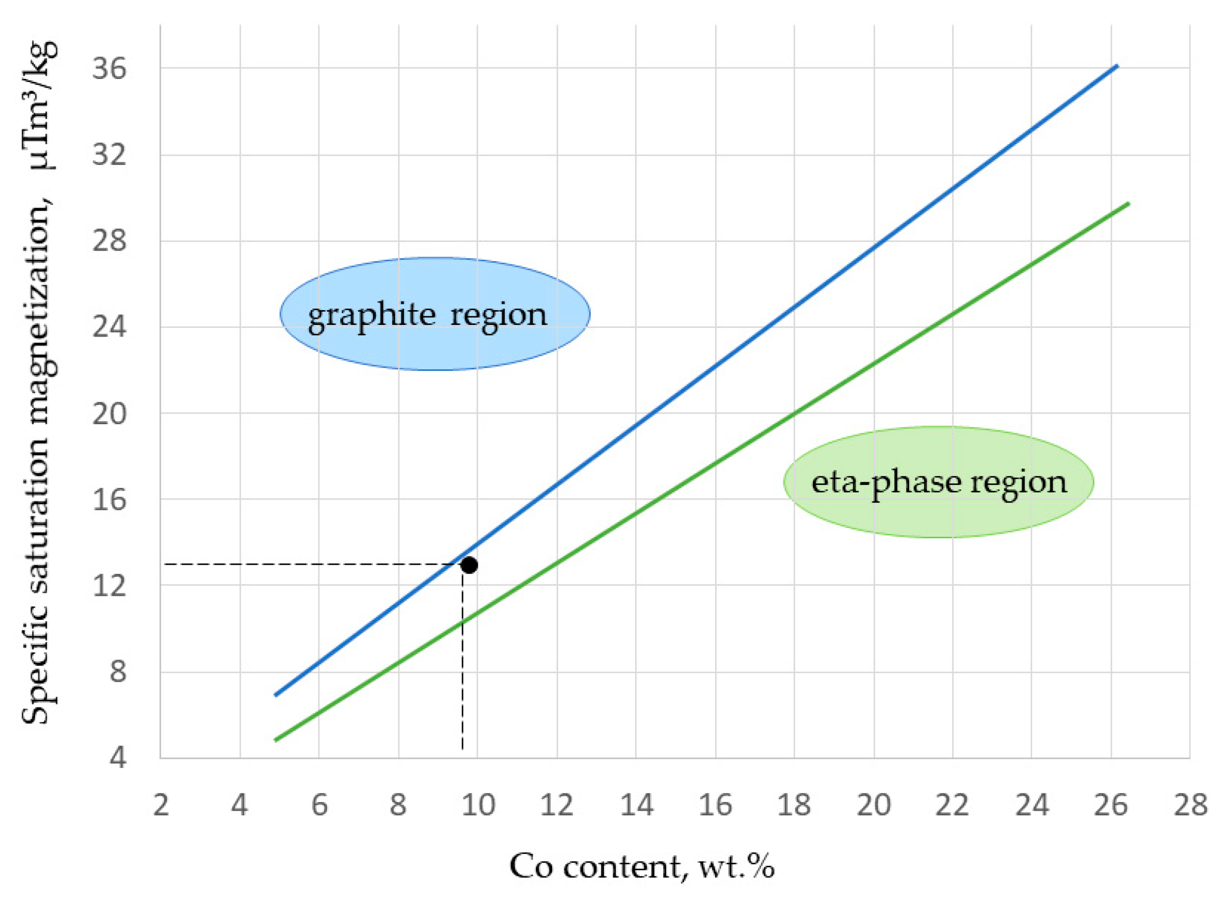
3C carbides possess higher densities than WC and Co constituents, which was not the case here. Magnetic and coercivity properties testing results are presented in Table 3.
Analysis of the magnetic properties results indicates the absence of microstructural defects such as eta-phase or graphite formation, thus confirming the proper adjustment of the sintering atmosphere, Figure 3. Coercive properties analysis was used as a method of indirect confirmation of nano grain size structure after sintering. The average value of the coercive force of 41.73 kA/m indicates the nano WC grain size (<0.2 µm) achieved by the proper contents of grain grow inhibitors (VC, Cr2C3) adjusted to the WC and Co content [39].
Surface roughness parameters were measured on an as-sintered surface and on a polished surface, Table 4.
Analysis of the measured mechanical properties including hardness, fracture toughness, and Young’s modulus indicates the formation of very hard cermet with average hardness of 2014.5 HV30, as shown in Table 5. When comparing the substrate hardness value with literature data for commercially available materials of similar chemical composition, superior hardness values are detected with still relatively high fracture toughness [50,
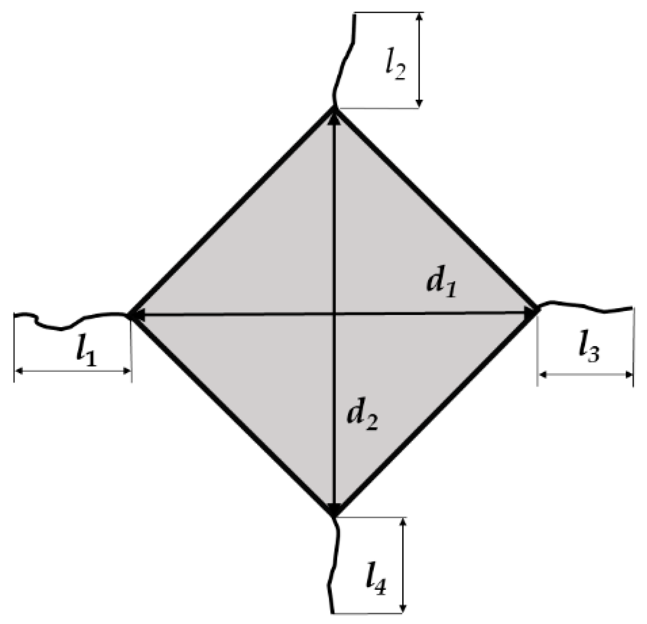
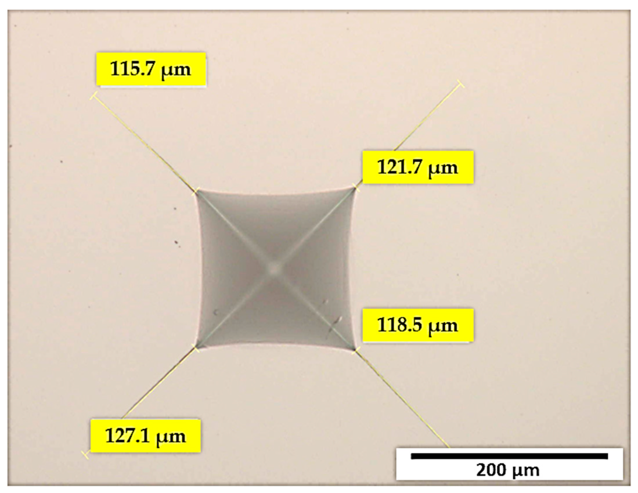
51]. The cracks that originate from the tip of the Vickers imprint are shown in Figure 4.
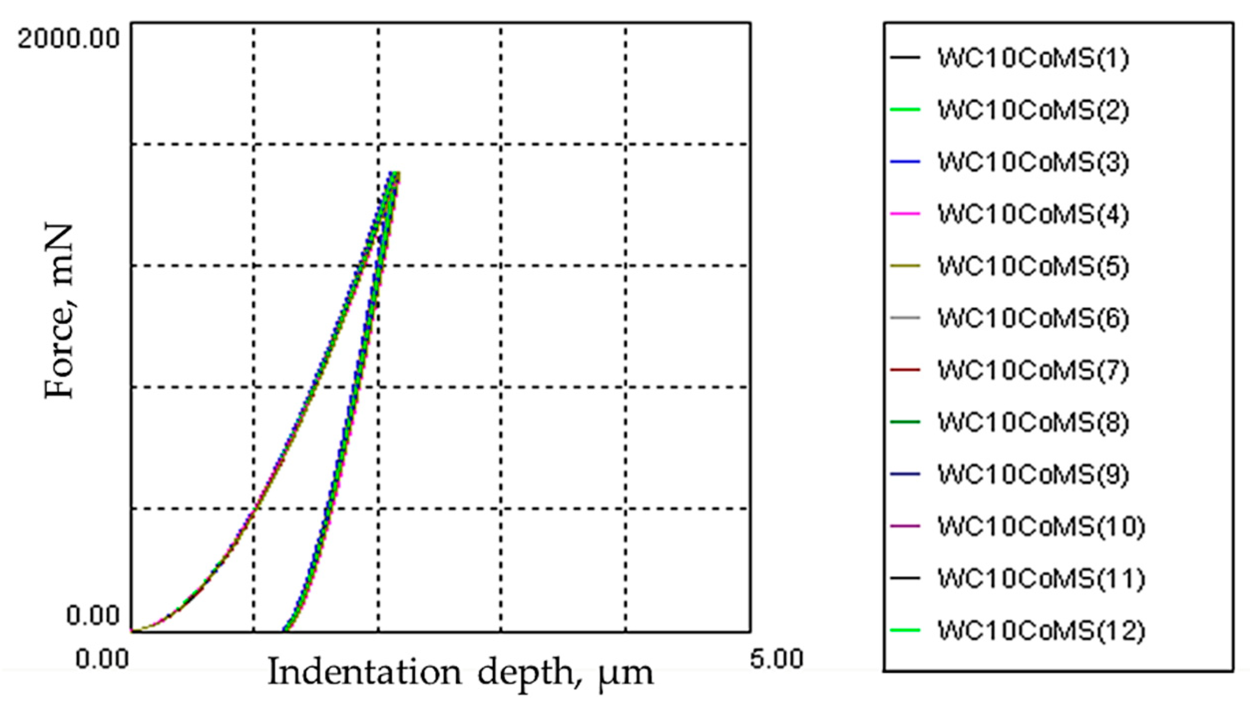
Figure 5 presents the characteristic force–displacement curves obtained by nanoindentation measurements, by which Young’s modulus value of 503.6 GPa was determined. The following values provided by the diamond indenter manufacturer were used: νi = 0.075 (indenter’s Poisson coefficient), Ei = 890 GPa (indenter’s modulus of elasticity), and νs = 0.225 (Poisson’s ratio of cemented carbide with 10 wt.% Co) [36,44,52,53].
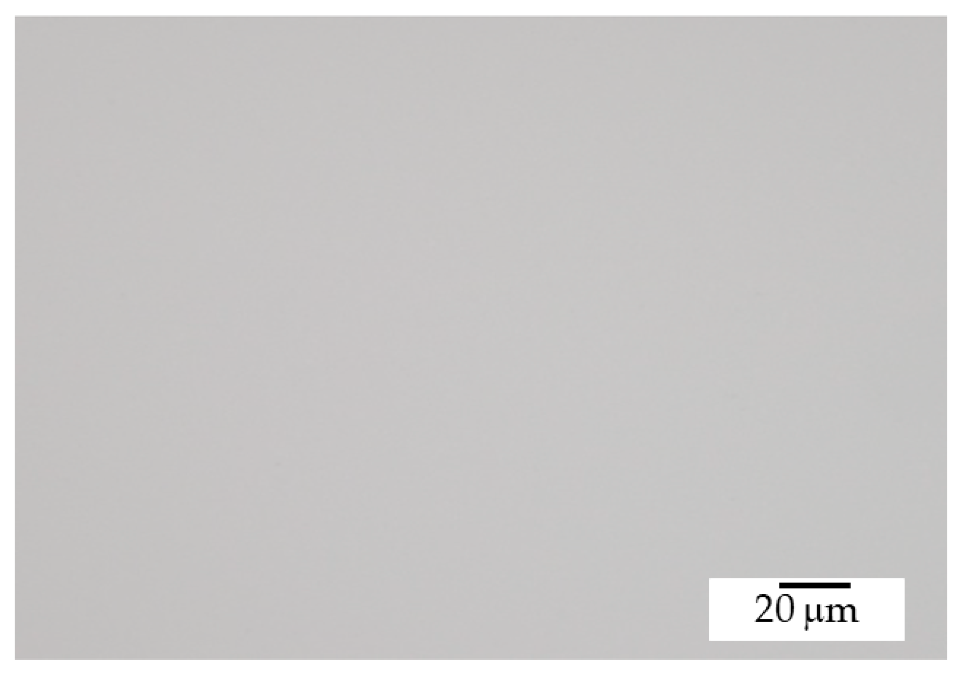
Comparison of the WC-10Co surface optical micrograph (Figure 6) with the photomicrographs specified in ISO 4499-4:2016 [54] indicates the absence of microstructural defects (cracks, pores, unbound carbon) on the submicron level. The degree of porosity and content of unbound carbon can be classified as A00 and C00, respectively [54,55]. These results correlate with values of density and magnetic properties.
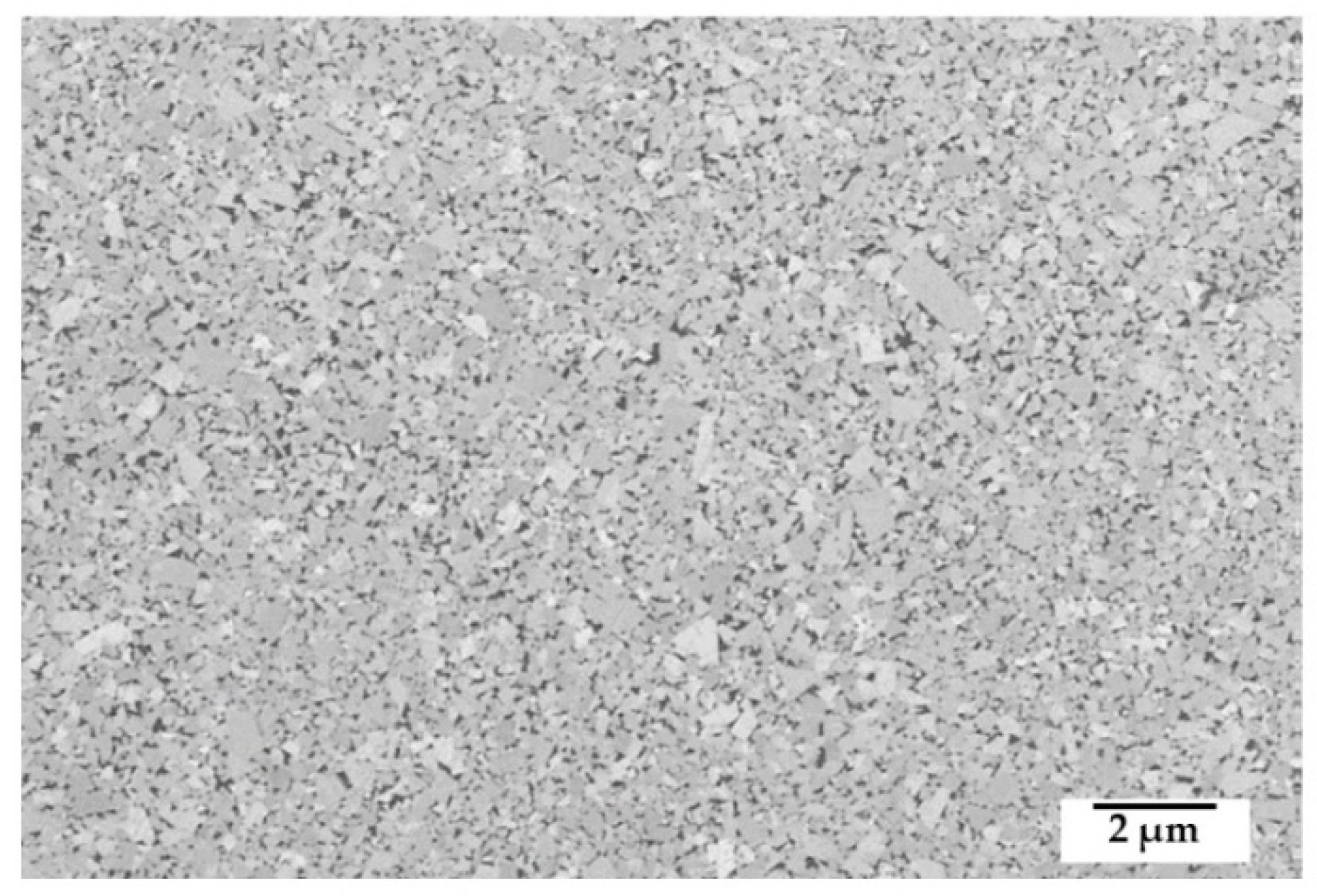
Figure 7 presents the electron micrograph of the WC-10Co substrate at 5000× magnification.
The FESEM micrograph of the sintered sample points to a homogeneous microstructure composed of very fine WC carbide grains of polygonal shape uniformly distributed in the Co matrix. The microstructure defects such as carbide grouping and excessive grain growth were not detected. The carbide grain size was determined by the AGI method on FESEM micrograph at a magnification of 20,000 times, as shown in Figure 8.
The average value of WC grain size of 197.03 ± 0.63 nm was measured. It is evident that the sintering was not affected on the grain growth and the carbide grains remained in the nanoscale range. This is also confirmed the results of coercive measurements.
XRD analysis of the WC-Co sample showed the presence of two crystal phases: WC constituent with an HCP (hexagonal close packed) lattice and Co constituent with an FCC (face-centered cubic) structure, Figure 9.

3.2. Coating

The coating of unpolished (as-sintered) surface of substrate with roughness parameters present in Table 6 was intended to imitate the industrial PACVD process, and thus bring it closer to wider commercialization.
The coating roughness analysis on unpolished surface showed slightly higher characteristic parameters. The value Ra is similar before and after coating. Increasing the Rz parameter can be related to the dedusting of the samples before the coating itself. Inert gas ions hitting the surface of the sample caused the outbreak of softer cobalt particles from the surface.
The coating thickness results show the TiBN coating to be the thinnest. The TiN coating is almost twice as thick with thicknesses of 3.10 µm. The thickest is TiCN coating with an average thickness of 5.33 µm.
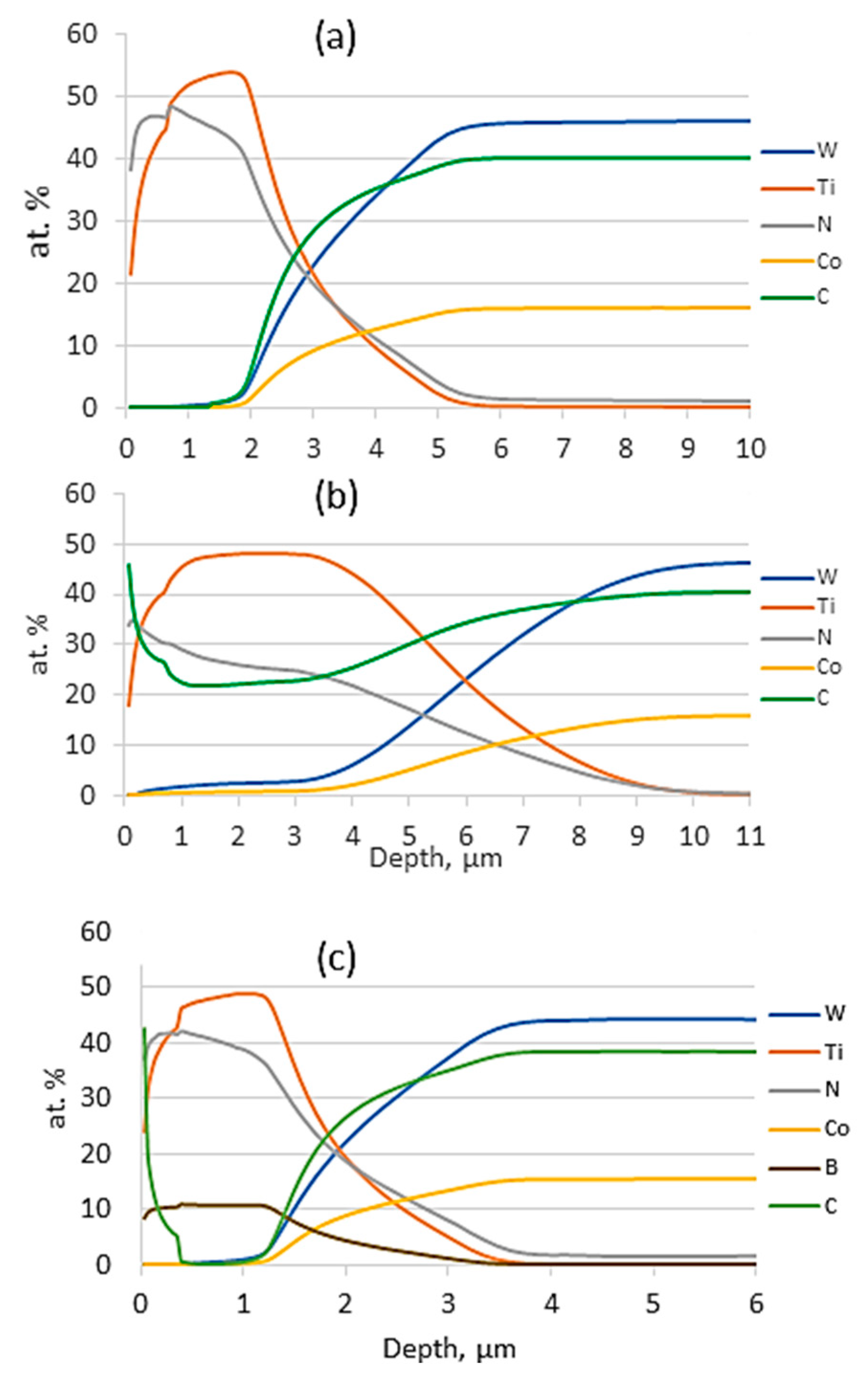
The results of the QDP analysis are shown in Figure 10. QDP analysis of the WC-10Co-TiN sample shows dominant presence of Ti and N up to a depth of ~3 μm, after which W, C, and Co content is detected, indicating substrate material. For the WC-10Co-TiCN sample, Ti, N, and C are present in a layer of ~5.2 μm in depth. In the TiCN coating, C is mainly concentrated in the upper layer of the coating, indicating the existence of a final TiCN layer formed by a relatively long deposition time of 1000 s, while N is mostly pronounced in the backing TiN layer at a depth of ~0.2 μm and, from there, decreases towards the coating/substrate interface. This confirms the existence of a supporting TiN layer and a gradual transition from the TiN to the TiCN layer. With the TiBN coating, the B content increases on the surface of the coating, while the N content decreases. A high B content on the surface itself with a slightly lower N content indicates the formation of a TiB2 top layer. The N content reaches a maximum at a depth of ~0.3 μm owing to the formation of a relatively thick TiN layer deposited for 1200 s, after which its content decreases because of transition into 30 gradient TiN/TiB2 alternations. At a depth of ~2 μm, the content of Ti, B, and N decreases to zero with a simultaneous increase in W, C, and Co owing to the transition of the coating to the substrate, which is characteristic of other samples as well, but at slightly greater depths.
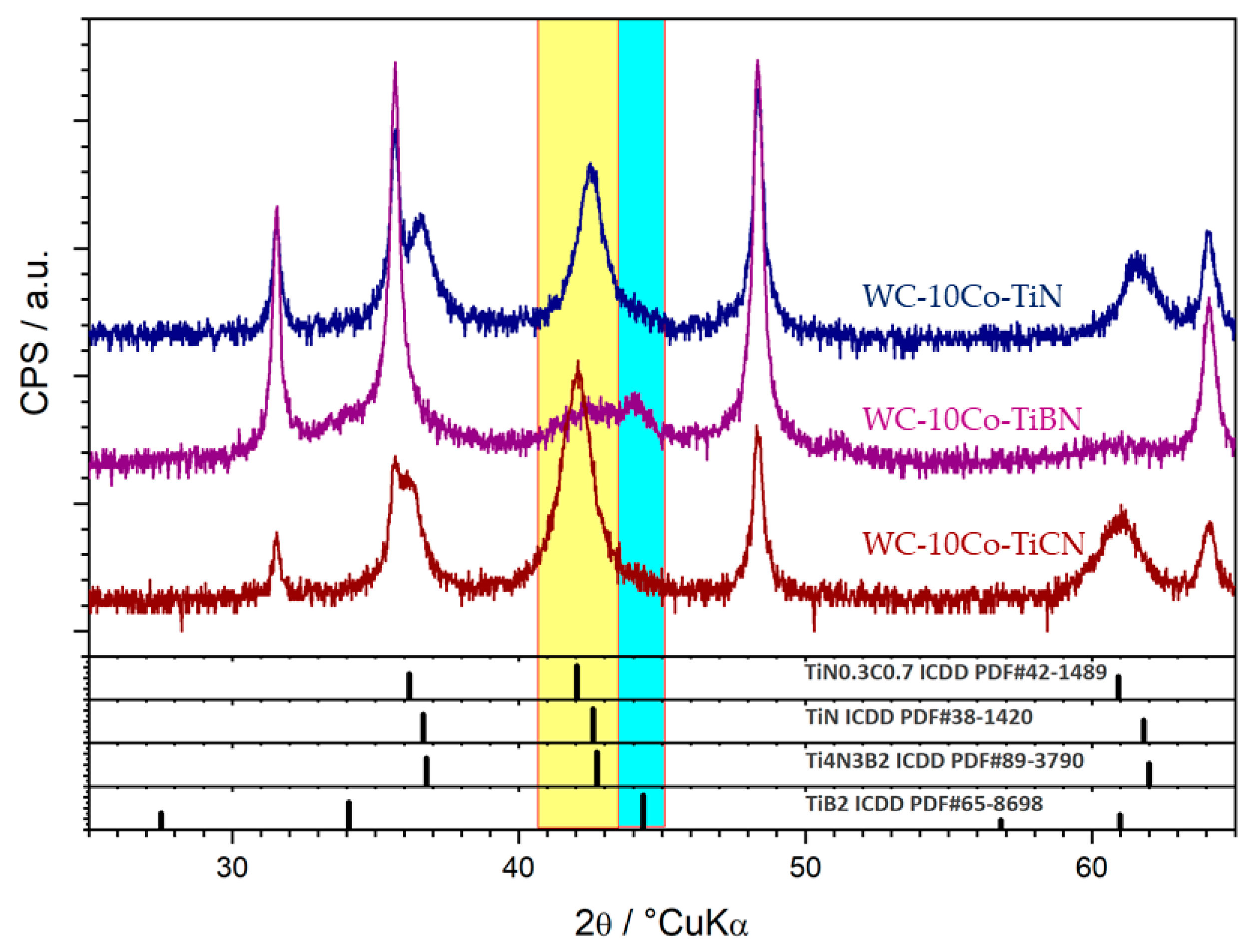
The results of the XRD analysis performed on three samples, each with a different type of coating, are shown in Figure 11. Samples of WC-Co cemented carbides coated with uniform layer consisted of the following: (1) interchanging titanium nitride and boron titanium layers, (2) titanium nitride, and (3) interchanging titanium nitride and titanium carbide layers. The major phase is the hexagonal P-6m2 tungsten carbide (WC, ICDD PDF#51-0939), which is the characteristic of the substrate. Surface treatments are manifested as follows: weak peak at 44° 2θ suggests the presence of hexagonal P6/mmm titanium boride (TiB2, ICDD PDF#65-8698) in trace amounts. A weak and much broader peak at 42° 2θ suggests the presence of cubic Fm-m3 titanium nitride (TiN, ICDD PDF#38-1420), and basically the same can be said for cubic Fm-m3 titanium carbide (TiC, ICDD PDF#65-8805). Cubic Fm-m3 titanium carbonitride (TiC0.7N0.3, ICDD PDF#42-1489) may possibly be observed in traces as well. The broadness of the peak at 42° 2θ may indicate the presence of an additional phase, instead of titanium nitride or overlapping with titanium nitride; the titanium boronitride (Ti4N3B2, ICDD PDF#87-3790). The titanium nitride, titanium carbide, titanium carbonitride, and titanium boronitride phases are almost isostructural, with very similar diffraction patterns, thus not allowing definite assignation. The XRD analysis confirmed that the coating does not cause the forming of microstructural defects (η-phase, unbound carbon) in the surface layers of the substrate.
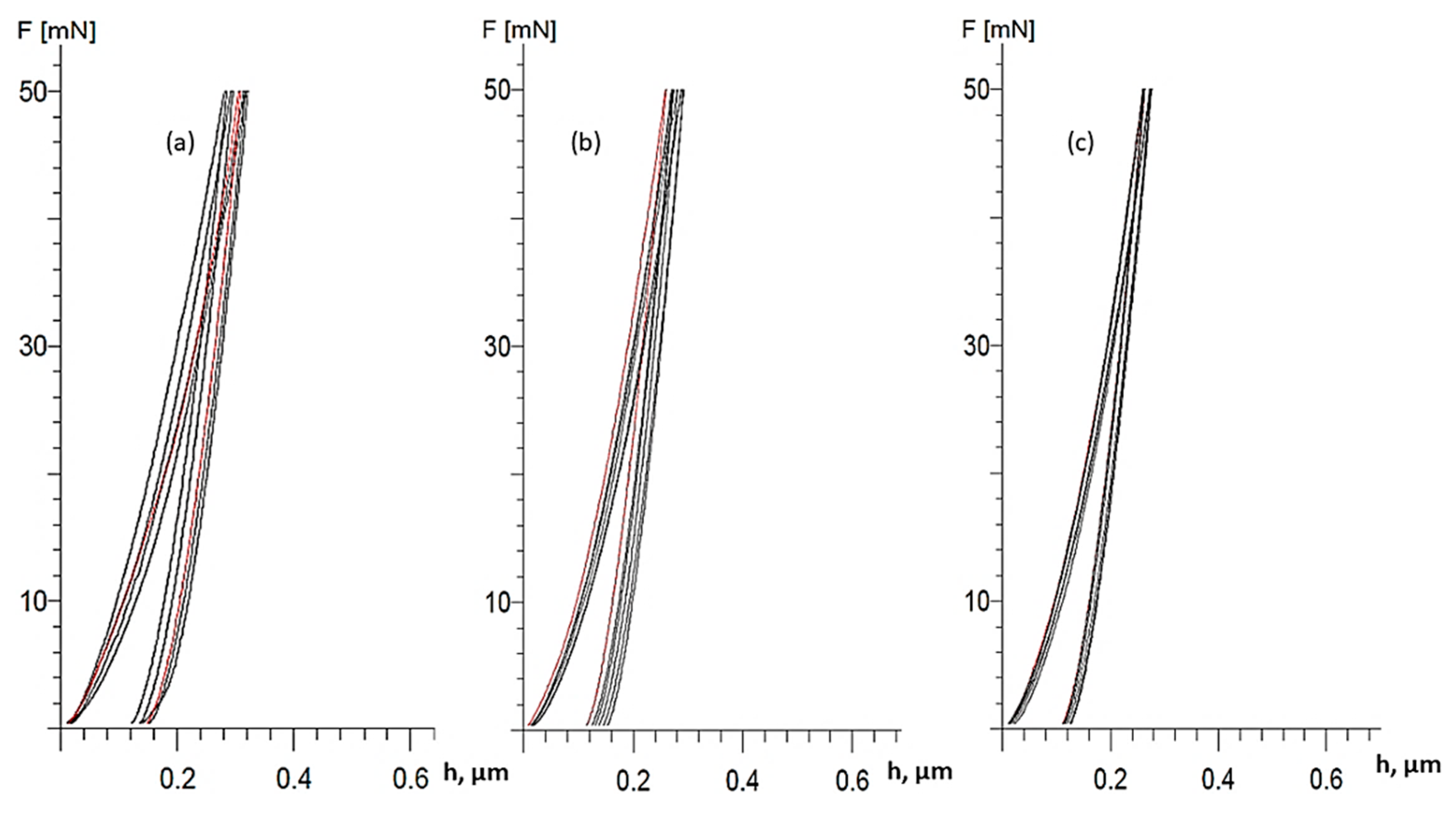
Using the force (F)–indentation depth (h) curves (Figure 12) obtained by nanoindentation, the values of the indentation Young’s modulus (EIT) of the coatings were determined. Table 7 presents the results of EIT and coatings’ microhardness.
A very high microhardness of the TiBN layer ranging from 3631 HV0.005 to 3732 HV0.005 was measured. TiBN coating exhibited the highest microhardness and modulus of elasticity values with lowest indentation depth values when compared with TiN and TiCN coating.
Considering the relatively small test forces and the achieved indentation depths, many times smaller than the thickness of the coatings, it is evident that the hardness of the substrate did not affect the hardness results of the coating itself. The scatterings of the measured hardness values are not as large as could be expected owing to the applied low indentation load and the high sensitivity of the method.
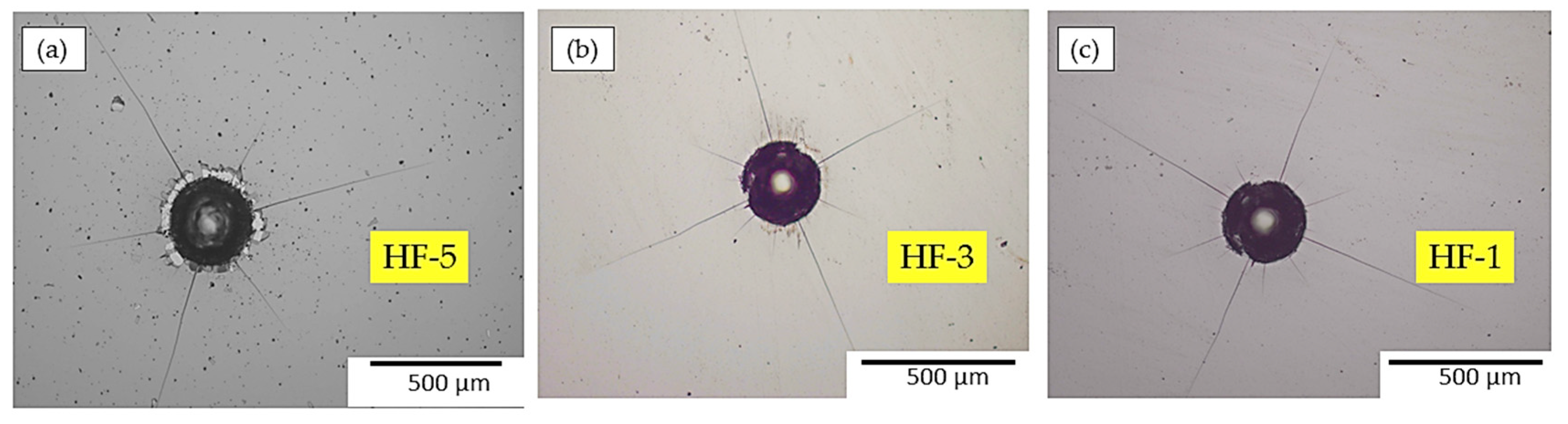
The Rockwell method was used as a method for a quick and simple testing of the adequate coating adhesion. The adhesion testing was performed with five indentations per each coating. Visual analysis of the cracks and delamination of the coating at indentation area caused by localized stresses and deformation was conducted, Figure 13. These phenomena are classified into several classes in accordance with VDI 3198 [56].
The sample with TiN coating exhibited adhesion in the classes HF-5, which means mostly satisfactory adhesion with low delamination (peeling) of the coating. However, it is this occurrence of delaminated areas that suggests that the TiN coating can hardly withstand adverse exploitation conditions. A sample with TiCN coating is characterized by better adhesion class HF3, which indicates the absence of delamination or its slight appearance with a larger number of cracks that form around the impression. The specimen with TiBN coating showed the best adhesion of class HF1 with the appearance of few small cracks around the impression.
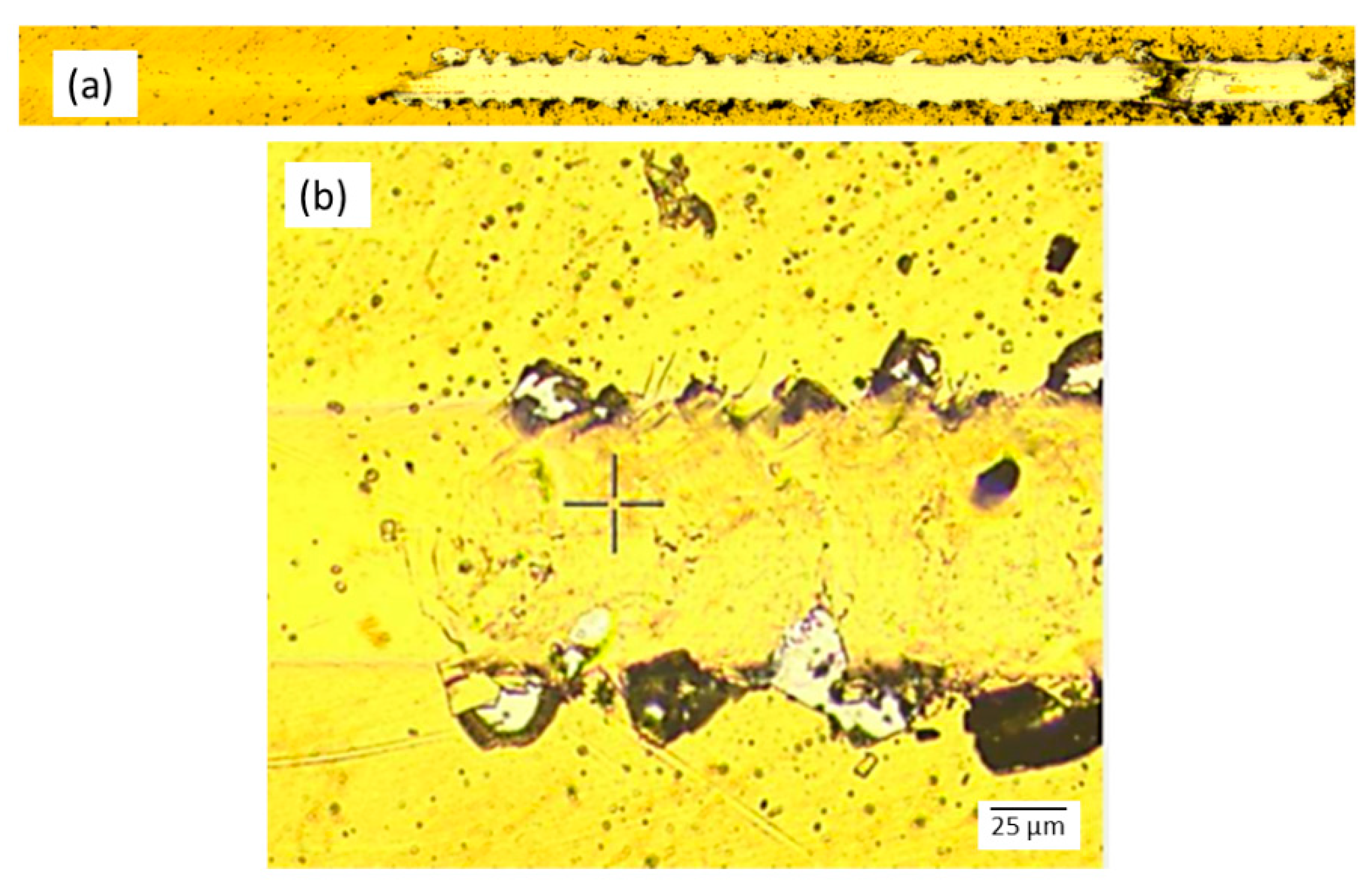
The results of the scratch test confirmed the indications obtained by the Rockwell test, Table 8. The lowest average critical fracture force (Lc2) of 27.11 N was obtained for TiN coating. Higher quality TiCN coating showed average values of 35.52 N, while no occurrence of delamination was detected for TiBN coating even at a force of 50 N. The TiN coating exhibited separation and delamination, which occurred even at low forces equal to Lc2, Figure 14. A higher force of about 46 N was required to penetrate the TiCN coating.
The TiBN coating and its coating process can be considered very successful in terms of adhesion, as it was able to withstand a maximum force of 50 N without traces of separation and penetration.

4. Conclusions

A PACVD coating was used to obtain nanostructured WC-Co cemented carbides coated with multilayered gradient coatings. The presented study provides nano-grain carbides consolidating process set-up, selection of PACVD process parameters for three different coatings (TiN, TiCN, TiBN), laboratory tests of coatings, as well as substrate/coating interface. Therefore, coated cemented carbides obtained in this study present materials with a wide range of potential applications in medicine, such as bone cutting tools, or small diameter drills with nozzles such as those used in dentistry.
Based on the results of physical and mechanical characterization of proposed coated cemented carbide materials, it is possible to conclude the following:
(i)
The described consolidating process was successful in producing nano grain size substrates of homogeneous microstructure, without pores, eta phase, or unbound carbon present.
(ii)
The PACVD process successfully produced three coating systems on a carbide substrate: single-layer TiN coating, harder multilayer gradient TiCN coating (composed of interchanging TiN and TiCN layers), and the hardest multilayer gradient TiBN coating composed of TiN and TiB2 layers.
(iii)
No significant difference was indicated for the roughness of the TiN, TiCN, and TiBN coatings. When comparing these values to the roughness values obtained prior to coating, uniform growth of all tested coatings over the entire surface of the substrates can be confirmed.
(iv)
The adhesion tests show that the coating architecture itself and its complexity affect to some extent the adhesion results. Single-layer TiN coating exhibited the worst adhesion. Some delamination of the TiCN coating was also detected, while for the TiBN coating, no traces of delamination were detected, indicating excellent adhesion. This can be attributed to higher residual stresses in the TiN and TiCN coatings arising from their significantly different coefficients of thermal expansion.
(v)
Coating thickness was shown to be a crucial adhesion contributor.
(vi)
The TiBN WC-Co coated samples were shown to be superior in all physical and mechanical properties when compared with TiN and TiCN coated samples.
The results presented confirmed that the PACVD process can be successfully utilized for thin gradient hard coatings’ deposition on nanostructured cemented carbides, creating a base material/coating system that can improve the mechanical and physical properties of cemented carbides as well as product life extension.

Supplementary Materials

The following are available online at https://www.mdpi.com/article/10.3390/coatings11070823/s1, Table S1: Sample polishing parameters, Figure S1: TiN coating process scheme, Table S2: TiN coating process parameters, Table S3: TiCN coating process parameters, Figure S2: TiCN coating process scheme, Table S4. TiBN coating process parameters, Figure S3: TiBN coating process scheme.

Author Contributions

Conceptualization, D.Ć. and M.S.; methodology, D.Ć. and M.Š.M.; validation, D.Ć., M.S., and Ž.A.; formal analysis, D.Ć., M.S., and M.Š.M.; data curation, M.S.; writing—original draft preparation, D.Ć. and M.Š.M.; writing—review and editing, M.S. and Ž.A. All authors have read and agreed to the published version of the manuscript.

Funding

This research received no external funding.

Institutional Review Board Statement

Not applicable.

Informed Consent Statement

Not applicable.

Data Availability Statement

Data sharing not applicable.

Conflicts of Interest

The authors declare no conflict of interest.

References

  1. Narasimha, M.; Ramesh, S. Coating performance on carbide inserts. Int. J. Eng. Res. 2014, 2, 175–179. [Google Scholar]
  2. Laugier, M.T. Adhesion of TiC and TiN coatings prepared by chemical vapour deposition on WC-Co-based cemented carbides. J. Mater. Sci. 1986, 21, 2269–2272. [Google Scholar] [CrossRef]
  3. Narasimhan, K.; Boppana, S.P.; Bhat, D.G. Development of a graded TiCN coating for cemented carbide cutting tools—A design approach. Wear 1995, 188, 123–129. [Google Scholar] [CrossRef]
  4. Kainz, C.; Schalk, N.; Tkadletz, M.; Mitterer, C.; Czettl, C. Microstructure and mechanical properties of CVD TiN/TiBN multilayer coatings. Surf. Coat. Technol. 2019, 370, 311–319. [Google Scholar] [CrossRef]
  5. Casas, B.; Lousa, A.; Calderón, J.; Anglada, M.; Esteve, J.; Llanes, L. Mechanical strength improvement of electrical discharge machined cemented carbides through PVD (TiN, TiAlN) coatings. Thin Solid Films 2004, 447, 258–263. [Google Scholar] [CrossRef]
  6. Czechowski, K. Effect of nanostructured multilayer coatings on functional properties of tools. Mechanik 2017, 90, 28–33. [Google Scholar] [CrossRef] [Green Version]
  7. Garcia, J.; Pitonak, R. The role of cemented carbide functionally graded outer-layers on the wear performance of coated cutting tools. Int. J. Refract. Met. Hard Mater. 2013, 36, 52–59. [Google Scholar] [CrossRef]
  8. Booth, L.; Catledge, S.A.; Nolen, D.; Thompson, R.G.; Vohra, Y.K. Synthesis and characterization of multilayered diamond coatings for biomedical implants. Materials 2011, 4, 857–868. [Google Scholar] [CrossRef] [Green Version]
  9. Wang, L.; Li, L.; Li, G.; Ma, Q. Improved adhesion of tialsin nanocomposite coatings on cemented carbide substrate by pre-implantation. Coatings 2019, 9, 209. [Google Scholar] [CrossRef] [Green Version]
  10. Park, J.; Kim, D.J.; Kim, Y.K.; Lee, K.H.; Lee, H.; Ahn, S. Improvement of the biocompatibility and mechanical properties of surgical tools with TiN coating by PACVD. Thin Solid Films 2003, 435, 102–107. [Google Scholar] [CrossRef]
  11. Deng, X.; Zheng, Z.C.; Ding, Z.L.; Wang, J.H. Erosion wear of ceramic and cemented carbide nozzles in dry sand blasting process. Br. Ceram. Trans. 2003, 102, 61–65. [Google Scholar] [CrossRef]
  12. Ding, Z.; Deng, J.; Zen, X.; Wu, J.; Zou, Y. Thermal erosion of WC-based cemented carbide nozzles by coal water slurry. Int. J. Refract. Met. Hard Mater. 2008, 26, 334–339. [Google Scholar]
  13. Azadi, M.; Rouhaghdam, A.S.; Ahangarani, S. Mechanical Behavior of TiN/TiCN Multilayer Coatings and Ti(C, N) Multicomponent Coatings Produced by PACVD. Strength Mater. 2016, 48, 279–289. [Google Scholar] [CrossRef]
  14. García, J.; Collado Ciprés, V.; Blomqvist, A.; Kaplan, B. Cemented carbide microstructures: A review. Int. J. Refract. Met. Hard Mater. 2019, 80, 40–68. [Google Scholar] [CrossRef]
  15. Sproul, W.D.; Richman, M.H. Effect of the eta layer on TiC-coated, cemented-carbide tool life. J. Vac. Sci. Technol. 1975, 12, 842. [Google Scholar] [CrossRef]
  16. Sarin, V.K.; Lindstrom, J.N. The effect of eta phase on the properties of CVD TiC - coated cemented carbide cutting tools. J. Electrochem. Soc. 1979, 126, 1281. [Google Scholar] [CrossRef]
  17. Formisano, A.; Capece Minutolo, F.; Caraviello, A.; Carrino, L.; Durante, M.; Langella, A. Influence of eta-phase on wear behavior of WC-Co carbides. Adv. Tribol. 2016, 2016, 1–6. [Google Scholar] [CrossRef] [Green Version]
  18. Mitterer, C.; Holler, F.; Reitberger, D.; Badisch, E.; Stoiber, M.; Lugmair, C.; Nöbauer, R.; Müller, T.; Kullmer, R. Industrial applications of PACVD hard coatings. Surf. Coat. Technol. 2003, 163–164, 716–722. [Google Scholar] [CrossRef]
  19. Tönshoff, K.K.; Blawit, C. Development and evaluation of PACVD coated cermet tools. Surf. Coat. Technol. 1997, 93, 119–127. [Google Scholar] [CrossRef]
  20. Lugmair, C.; Kullmer, R.; Nöbauer, R.; Mülleret, T. PACVD hard coatings for industrial applications. Surf. Coat. Technol. 2004, 2, 1041–1052. [Google Scholar]
  21. Azadi, M.; Rouhaghdam, A.S.; Ahangarani, S. Properties of TiC coating by pulsed DC PACVD. J. Coat. 2013, 2013, 1–6. [Google Scholar] [CrossRef] [Green Version]
  22. Arai, T.; Fujita, H.; Oguri, K. Plasma-assisted chemical vapor deposition of TiN and TiC on steel: Properties of coatings. Thin Solid Films 1988, 165, 139–148. [Google Scholar] [CrossRef]
  23. Jarms, C.; Stock, H.R.; Berndt, H.; Bartsch, K.; Leonhardt, A.; Arnold, B. Influence of the PACVD process parameters on the properties of titanium carbide thin films. Surf. Coat. Technol. 1998, 98, 1547–1552. [Google Scholar] [CrossRef]
  24. Kim, D.; Cho, Y.; Lee, M. Properties of TiN–TiC multilayer coatings using plasma-assisted chemical vapor deposition. Surf. Coat. Technol. 1999, 116–119, 906–910. [Google Scholar] [CrossRef]
  25. Shanaghi, A.; Sabour Rouhaghdam, A.; Ahangarani, S.; Chu, P.K. Effect of plasma CVD operating temperature on nanomechanical properties of TiC nanostructured coating investigated by atomic force microscopy. Res. Bull. 2012, 47, 2200–2206. [Google Scholar] [CrossRef]
  26. Sakoman, M.; Ćorić, D.; Aleksandrov Fabijanić, T.; Kovačić, S. Tribological properties of coatings applied on near-nano and nanostructured WC-Co hardmetals by using plasma-assisted chemical vapour deposition technique. Trans. FAMENA 2020, 44. [Google Scholar] [CrossRef]
  27. Jindal, P.C.; Santhanam, A.T.; Schleinkofer, U.; Shuster, A.F. Performance of PVD TiN, TiCN and TiAlN coated cemented carbide tools in turning. Int. J. Refract. Metals Hard Mater. 1999, 17, 163–170. [Google Scholar] [CrossRef]
  28. Pötschke, J.; Richter, V.; Mayer, M. Manufacturing and Properties of Polycrystalline WC-Co Based Cemented Carbides. In Proceedings of the World PM 2016, Hamburg, Germany, 9–13 October 2016. [Google Scholar]
  29. Xie, H.; Song, X.; Yin, F.; Zhang, Y. Effect of WC/Co coherency phase boundaries on Fracture toughness of the nanocrystalline cemented carbides. Sci. Rep. 2016, 6, 31047. [Google Scholar] [CrossRef]
  30. Bahroun, K.; Behm, H.; Mitschker, F.; Awakowicz, P.; Dahlmann, R.; Hopmann, C. Influence of layer type and order on barrier properties of multilayer PECVD barrier coatings. J. Phys. D Appl. Phys. 2013, 47, 5201. [Google Scholar] [CrossRef]
  31. Aleksandrov Fabijanić, T. Development of Reference Vickers Hardness Blocks by Powder Metallurgy Process; Faculty of Mechanical Engineering and Naval Architecture, University of Zagreb: Zagreb, Croatia, 2014. [Google Scholar]
  32. Landek, D.; Jakovljević, S.; Alar, V.; Kovačić, S. Effect of steel substrate on the corrosion properties of a gradient multilayer TiN/TiCN coating deposited by the PACVD process. Mater. Corros. 2019, 70, 307–318. [Google Scholar] [CrossRef]
  33. Sakoman, M.; Ćorić, D.; Šnajdar Musa, M. Plasma-assisted chemical vapor deposition of TiBN coatings on nanostructured cemented WC-Co. Metals 2020, 10, 1680. [Google Scholar] [CrossRef]
  34. Kovacic, S. Influence of Nitriding and Coating on the Properties of Hot Work Tool Steels. Ph.D. Thesis, Faculty of Mechanical Engineering and Naval Architecture, Zagreb, University of Zagreb, Zagreb, Croatia, December 2015. [Google Scholar]
  35. Šnajdar Musa, M.; Sakoman, M.; Ćorić, D.; Fabijanić, T.A. Exploitation and wear properties of nanostructured WC-Co tool modified with plasma-assisted chemical vapor deposition TiBN coating. Metals 2021, 11, 333. [Google Scholar] [CrossRef]
  36. International Organization for Standardization. ISO 3369:2011. Impermeable Sintered Metal Materials and Hardmetals-Determination of Density; ISO: Geneva, Switzerland, 2011. [Google Scholar]
  37. Available online: http://www.hoppebaumdienst.de/Barat_Carbide_Group_Grades.pdf (accessed on 13 October 2014).
  38. International Organization for Standardization. ISO 4505: 2011. Hardmetals—Metallographic Determination of Porosity and Uncombined Carbon; ISO: Geneva, Switzerland, 2011. [Google Scholar]
  39. Yousfi, A. Microstructure Development of WC-Co Based Cemented Carbides During Creep Testing. Ph.D. Thesis, Chalmers University of Technology, Gothenburg, Sweden, 26 May 2016. [Google Scholar]
  40. International Organization for Standardization. ISO 6507-1:2018. Metallic Materials. Vickers Hardness Test. Test Method; ISO: Geneva, Switzerland, 2018. [Google Scholar]
  41. Aleksandrov Fabijanić, T.; Ćorić, D.; Šnajdar Musa, M.; Sakoman, M. Vickers indentation fracture toughness of near- nano and nanostructured WC-Co cemented carbides. Metals 2017, 7, 143. [Google Scholar] [CrossRef] [Green Version]
  42. Oliver, W.C.; Pharr, G.M. Measurement of hardness and elastic modulus by instrumented indentation: Advances in understanding and refinements to methodology. J. Mater. Res. 2004, 19, 3–20. [Google Scholar] [CrossRef]
  43. International Organization for Standardization. ISO 14577-1:2015. Metallic materials—Instrumented Indentation Test for Hardness and Materials Parameters—Part 1: Test Method; ISO: Geneva, Switzerland, 2015. [Google Scholar]
  44. Sergejev, F.; Antonov, M. Comparative study on indentation fracture toughness measurements on cemented carbides. Proc. Estonian Acad. Sci. Eng. 2006, 12, 388–398. [Google Scholar]
  45. Sheikh, S.; M’Saoubi, R.; Flasar, P.; Schwind, M.; Persson, T.; Yang, J.; Llanes, L. Fracture toughness of cemented carbides: Testing method and microstructural effect. Int. J. Refract. Met. Hard Mater. 2015, 49, 153–160. [Google Scholar] [CrossRef] [Green Version]
  46. International Organization for Standardization. ISO 4499-2:2008_Hardmetals—Metallographic Determination of Microstructure—Part 2: Measurement of WC Grain Size; ISO: Geneva, Switzerland, 2008. [Google Scholar]
  47. Deutsches Institut fur Normung E.V. DIN EN 1071-2:2003_Advanced Technical Ceramics-Methods of Test for Ceramic Coatings-Part 2: Determination of Coating Thickness by the Crater Grinding Method; Deutsches Institut fur Normung E.V.: Berlin, Germany, 2003. [Google Scholar]
  48. International Organization for Standardization. ISO EN EN 1071-8:2004_Rockwell Indentation Test for Evaluation of Adhesion of Ceramic Coatings; ISO: Geneva, Switzerland, 2004. [Google Scholar]
  49. International Organization for Standardization. ISO 1071-3:2008_Fine Ceramics (Advanced Ceramics, Advanced Technical Ceramics)-Determination of Adhesion of Ceramic Coatings by Scratch Testing; ISO: Geneva, Switzerland, 2008. [Google Scholar]
  50. Roebuck, B.; Gee, M.; Bennett, E.G.; Morrell, R. A national measurement good practice guide No.20-mechanical tests for hardmetals NPL. Ceramics 1999, 20, 1–74. [Google Scholar]
  51. Jia, K.; Fischer, T.E.; Gallois, B. Microstructure, hardness and toughness of nanostructured and conventional WC-Co composites. Nanostruct. Mater. 1998, 10, 875–891. [Google Scholar] [CrossRef]
  52. Hess, P. The mechanical properties of various chemical vapor deposition diamond structures compared to the ideal single crystal. J. Appl. Phys. 2012, 111, 051101. [Google Scholar] [CrossRef] [Green Version]
  53. Wentorf, R.H.; De Vries, R.C.; Bundy, F.P. Sintered superhard. Mater. Sci. 1980, 208, 873–890. [Google Scholar]
  54. International Organization for Standardization. ISO 4499-4:2016. Hardmetals—Metallographic Determination of Microstructure—Part 4: Characterization of Porosity, Carbon Defects and Eta-Phase Content; ISO: Geneva, Switzerland, 2016. [Google Scholar]
  55. Gille, G.; Bredthauer, J.; Gries, B.; Mende, B.; Heinrich, W. Advanced and new grades of WC and binder powder—Their properties and application. Int. J. Refract. Hard Met. 2000, 18, 87–102. [Google Scholar] [CrossRef]
  56. Verein Deutscher Ingenieure Normen, VDI 3198; VDI-Verlag: Dusseldorf, German, 1991.
Figure 1. Vickers indentation and cracks.
Coatings 11 00823 g001
Figure 2. Calotest method and imprint.
Coatings 11 00823 g002
Figure 3. Influence of magnetic saturation and Co content on the formation of graphite and eta phase [39].
Coatings 11 00823 g003
Figure 4. Vickers imprint (HV 30) and cracks on the WC-10Co substrate.
Coatings 11 00823 g004
Figure 5. Nanoindentation force versus indentation depth curves for substrate WC-10Co.
Coatings 11 00823 g005
Figure 6. WC-10Co surface optical micrograph.
Coatings 11 00823 g006
Figure 7. Field emission scanning electron microscopy (FESEM) micrograph of the WC-10Co substrate.
Coatings 11 00823 g007
Figure 8. Grain size determination of the WC-10Co substrate.
Coatings 11 00823 g008
Figure 9. X-ray diffraction (XRD) pattern of the WC-10Co substrate.
Coatings 11 00823 g009
Figure 10. Quantitative depth analysis profile of coated sample: (a) WC-10Co-TiN; (b) WC-10Co-TiCN; (c) WC-10Co-TiBN.
Coatings 11 00823 g010
Figure 11. XRD patterns of coated samples: WC-10Co-TiN, WC-10Co-TiCN, and WC-10Co-TiBN.
Coatings 11 00823 g011
Figure 12. Nanoindentation force versus indentation depth curves for coated sample: (a) WC-10Co-TiN; (b) WC-10Co-TiCN; and (c) WC-10Co-TiBN.
Coatings 11 00823 g012
Figure 13. Optical micrographs of Rockwell C adhesion test indentations: (a) WC-10Co-TiN; (b) WC-10Co-TiCN; and (c) WC-10Co-TiBN.
Coatings 11 00823 g013
Figure 14. Optical micrographs of scratch paths in the TiN coating deposited on the WC-10Co substrate: (a) wear trace after scratch test; (b) critical part of a scratch track with coating delamination.
Coatings 11 00823 g014
Table 1. Coated sample types.
Substrate Coating TypeSample Label
WC-10CoTiNWC-10Co-TiN
WC-10CoTiCN (TiN-TiCN)WC-10Co-TiCN
WC-10CoTiBN (TiN-TiB2)WC-10Co-TiBN
Table 2. WC-10Co substrate densities.
SampleTheoretical Density, g/cm3Measured Density, g/cm3Relative Density, %
WC-10Co14.3014.32 ± 0.01100.12
Table 3. WC-10Co substrate magnetic and coercive properties.
SampleSpecific Saturation Magnetization, µTm3/kgRelative Saturation Magnetization, %Coercive Force, kA/m
WC-10Co14.47 ± 0.3178.73 ± 0.5641.73 ± 0.29
Table 4. WC-10Co substrate roughness parameters.
SampleSurface Roughness Parameters, μm
RaRz
WC-10Co non-polished0.146 ± 0.0151.242 ± 0.323
WC-10Co polished0.088 ± 0.0110.549 ± 0.028
Table 5. Mechanical properties of WC-10Co substrate.
SampleHardness, HV30Fracture Toughness, MPa√mYoung’s Modulus, GPa
WC-10Co2014.5 ± 4.69.09 ± 0.03503.6 ± 2.8
Table 6. Roughness parameters and coating thickness.
Coated Sample Surface Roughness Parameters, µmCoating Thickness, μm
RaRz
WC-10Co-TiN0.150 ± 0.0091.642 ± 0.1253.10 ± 0.23
WC-10Co-TiCN0.154 ± 0.0211.407 ± 0.0935.33 ± 0.25
WC-10Co-TiBN0.146 ± 0.0031.324 ± 0.1101.63 ± 0.16
Table 7. Results obtained by nanoindentation of coated samples.
SampleMicrohardness, HV 0.005Indentation Modulus of Elasticity EIT, GPaMaximum Indentation Depth, µm
WC-10Co-TiN2184.4 ± 61.6336.2 ± 35.50.305
WC-10Co-TiCN3220.6 ± 36.8398.8 ± 15.00.284
WC-10Co-TiBN3672.0 ± 135.3466.8 ± 25.30.250
Table 8. Results of the scratch test.
SampleCoating TypeCritical Coating Delamination Force, NAverage Delamination Force, N
WC-10Co-TiNTiNLC1-
LC227.11 ± 5.03
LC330.25 ± 6.55
WC-10Co-TiCNTiCN (TiN-TiCN)LC1-
LC235.52 ± 7.18
LC345.94 ± 2.85
WC-10Co-TiBNTiBN (TiN-TiB2)LC1-
LC2at 50 N, no delamination or penetration was observed
LC3at 50 N, no delamination or penetration was observed
Publisher’s Note: MDPI stays neutral with regard to jurisdictional claims in published maps and institutional affiliations.

