Article

Thermally Sprayed Nickel-Based Repair Coatings for High-Pressure Turbine Blades: Controlling Void Formation during a Combined Brazing and Aluminizing Process

Institut für Werkstoffkunde (Materials Science), Leibniz Universität Hannover, An der Universität 2, 30823 Garbsen, Germany
*
Author to whom correspondence should be addressed.
Coatings 2021, 11(6), 725; https://doi.org/10.3390/coatings11060725
Submission received: 28 April 2021 / Revised: 27 May 2021 / Accepted: 8 June 2021 / Published: 16 June 2021
(This article belongs to the Section Plasma Coatings, Surfaces & Interfaces)

Abstract

:
Turbine blades must withstand severe loading conditions and damage can occur during operation due to heat, pressure, foreign objects and hot gas corrosion, despite the protective coatings applied onto the turbine blades. Instead of replacing the damaged components, maintenance, repair and overhaul are key to extend the total service life. Besides welding, the repair of turbine blades by brazing is an established repair process in the industry and involves many individual steps that often require a high degree of manual work. In the present study, a hybrid joining and coating technology was developed to shorten the state-of-the-art process chain for repairing turbine blades. With this approach, a repair coating, which consists of a filler metal, a hot gas corrosion protective layer and an aluminum top layer, is applied by atmospheric plasma spraying. The coated turbine blade then undergoes a heat-treatment so that a brazing and aluminizing process is carried out simultaneously. Due to diffusion and segregation processes, pores can occur in the heat-treated coating. In the present study, a full factorial design of experiment was performed to reduce the pores in the coating. The microstructure of the repair coating was investigated by optical- and scanning electron microscopy (SEM), and the impact of the process parameters on the resulting microstructure is discussed.

1. Introduction

Thermal spraying is a high-performance process and is mainly used for producing coatings that reduce wear, enhance corrosion resistance or act as thermal barriers [1]. Examples of the manifold use of thermal spraying include the coating of cylinder liners in the automotive industry [2], the coating of calender rolls in the printing industry [3] and the coating of turbine blades in the aviation and power plant industry [4,5,6,7]. Turbine blades made of nickel-based alloys are mainly used in high pressure turbines in the aviation industry and in power plants for stationary gas turbines. Given the severe loading conditions encountered in these applications, efficient repair processes are of paramount importance for these expensive components. Typical repair processes for turbine blades are welding and brazing [8,9], and the main steps for repairing these are shown in Figure 1 [10].
The repair brazing process of turbine blades was the focus of the present study. In this context, the following approach represent the state-of-the-art:
First, the worn blade is stripped down to the nickel-based base material and cleaned, for example by fluoride ion cleaning (FIC). After inspection, localization and evaluation of existing defects, the repair filler metal is applied to the areas to be repaired. This is done manually with pastes using a dispensing needle, brush or spatula. Other filler metal application options are tapes, melt-spun foils or filler metal moldings. Due to the materials used, the brazing process is carried out in a vacuum furnace, while the brazing temperature is above the melting temperature of the filler metal. Wetting of the substrate material occurs, and the molten filler metal fills the gap to be brazed by capillary effects. The filler metal composition depends on whether the blades are made of monocrystalline or polycrystalline alloys. Nickel-based repair filler metals for polycrystalline turbine blades exist of two different powders, a nickel-based alloy and an additive alloy which does not melt during brazing. In addition, melting point depressing elements, such as boron and silicon, are added to the filler metal. Nickel-based brazing alloys without boron and silicon are used for single-crystal and directionally solidified alloys because the borides and silicides precipitates accumulate in the nickel matrix rather than at the grain boundaries, as in polycrystalline materials, thus degrading the mechanical properties [11]. Binary (NiMn37.6) and ternary (NiMn20Si2 and NiMn25Si2) alloys were developed for high-temperature vacuum brazing of 300 µm wide gaps in single-crystalline nickel-based superalloys [12]. Compared to TLP (transient liquid phase) technologies, which achieve epitaxial solidification of single-crystalline alloys only by long dwell times (several hours) and high temperatures, epitaxial healing of cracks can be achieved within a few minutes with the above alloys. After the vacuum brazing process, excess filler metal is removed by machining or grinding. If necessary, cooling air holes are added after the grinding process or reinserted by laser.
To protect the turbine blades against hot gas corrosion and oxidation, a MCrAlY coating (M = Ni and/or Co) is applied either by atmospheric plasma spraying (APS), high velocity oxygen fuel spraying (HVOF), vacuum plasma spraying (VPS) or electron beam physical vapor deposition (EB-PVD). The turbine blade is then subjected to an aluminizing process to further increase the hot gas corrosion resistance, which can be attributed to the formation of the β-phase (NiAl) [13]. This repair process is expensive and consists of several process steps. In earlier works, it is shown that the repair process for turbine blades can be shortened by using a two-stage hybrid joining and coating technology [14,15]. The idea of this hybrid technology is as follows:
The material structure of a high-pressure turbine blade is nickel-based, starting from the base material over the brazing alloy to the hot gas corrosion protective layer. The alloys are metallurgically compatible and can be matched to each other, especially the brazing alloys) and the hot gas corrosion protective systems. In addition, both systems are processed by powder metallurgy, which in turn suggests a common coating onto the turbine blade by thermal spraying.
In this hybrid technology the worn turbine blade receives a thermally sprayed repair coating consisting of the nickel-based filler metal, the hot gas corrosion protective layer (NiCoCrAlY) and finally an aluminum layer. The coated turbine blade then undergoes a heat-treatment combining brazing and aluminizing at the same time. This two-stage hybrid technology has both technical and economic advantages. The advantage is that large areas of the parts to be joined or repaired can be coated by thermal spraying in a near net shape manner and so that there is no need for grinding excess filler metal. Another advantage is that the aluminizing process can be carried out without a pack cementation or a special aluminizing furnace with a hazardous atmosphere.
The combination of thermally sprayed filler metal application together with the hot gas corrosion protective coating and the integration of the brazing process into the aluminizing process hold out the prospect of an innovation with considerable process chain shortening, which is relevant not only for turbine blade repair but also in principle for the high-quality repair of thermally, tribologically and/or corrosively highly stressed components with high added value (e.g., wind turbine, machine tool, printing machine as well as rail vehicles). The principle of this hybrid technology is shown in Figure 2.
For these studies Inconel 718 flat specimens were used as the base material. Inconel 718 was selected as a reference material because the properties of this nickel-alloy are well known and widely investigated [16,17,18,19]. The filler metal used was a NiCrSi-alloy (Ni650, also known as B-Ni5) and has the advantage that it consists only of three alloying elements. Silicon in this filler metal is the melting point depressant. NiCoCrAlY as the hot gas corrosion protective coating is state of the art. Two approaches were considered: The first one was to carry out the combined brazing/aluminizing process in a pack cementation. To get a microstructure nearly free of pores in the filler metal, a tailored temperature-time regime was used with a total duration of 36 h. The second approach was to avoid the pack cementation and the aluminum layer, which is at least responsible for the formation of the NiAl-phase (β-phase), was applied by thermal spraying as well and the time for brazing and aluminizing could be reduced to less than 30 min. However, the resulting microstructure of the brazed/aluminized coating still contains single areas of pores in the filler metal, which are caused due to diffusion- and segregation processes as well as the Kirkendall effect [20].
The microstructure of thermally sprayed coatings and their properties are influenced substantially by the spraying conditions and the materials used (substrate and coating materials). The microstructure also contributes to the character and properties of the coating-substrate system. Depending on the process used, thermally sprayed coatings have lamellar structures and are porous, heterogeneous and anisotropic. Furthermore, not completely melted and oxidized particles can occur in the layer [21].
In case of a combined brazing and aluminizing process, the heat treatment parameters additionally influence the microstructure of the coating. Thus, the influences of both the spraying and the heat treatment parameters on the resulting microstructure of a repair coating were investigated in the present study.

2. Materials and Methods

2.1. Materials

The substrate to be coated consisted of flat Inconel 718 specimens (30 mm × 30 mm × 2 mm). First, the specimens were blasted with EKF54 fused corundum (grain size from 250 to 355 µm). Thereafter the samples cleaned with isopropanol in an ultrasonic bath and subsequently coated using thermal spraying. Starting from the base material, the first layer is the filler metal (B-Ni5) with a thickness of 250 µm, followed by the MCrAlY layer with a thickness of 300 µm and finally an 80 µm thick aluminum layer. The chemical compositions of the materials used are shown in Table 1.

2.2. Coating Equipment

The coating of the Inconel 718 flat specimens was carried out by atmospheric plasma spraying. The coating parameters are listed in Table 2. For all experiments, the power of the plasma plume was kept constant. As the traverse velocity and the powder feed rate were variable parameters, cf. Table 2, the overrun was adjusted such as to keep the thickness of the individual layers constant as well.

2.3. Heat Treatment

The coated Inconel 718 flat specimens were heat treated in a high vacuum furnace. The pressure in the furnace chamber was about 10−5 mbar. The samples were heated at a rate of 20 K/min up to the given brazing temperature. The brazing temperatures were 1090 and 1190 °C and the brazing dwells were 5 and 15 min, followed by free cooling under vacuum. This heat treatment represents a conventional standard brazing process.

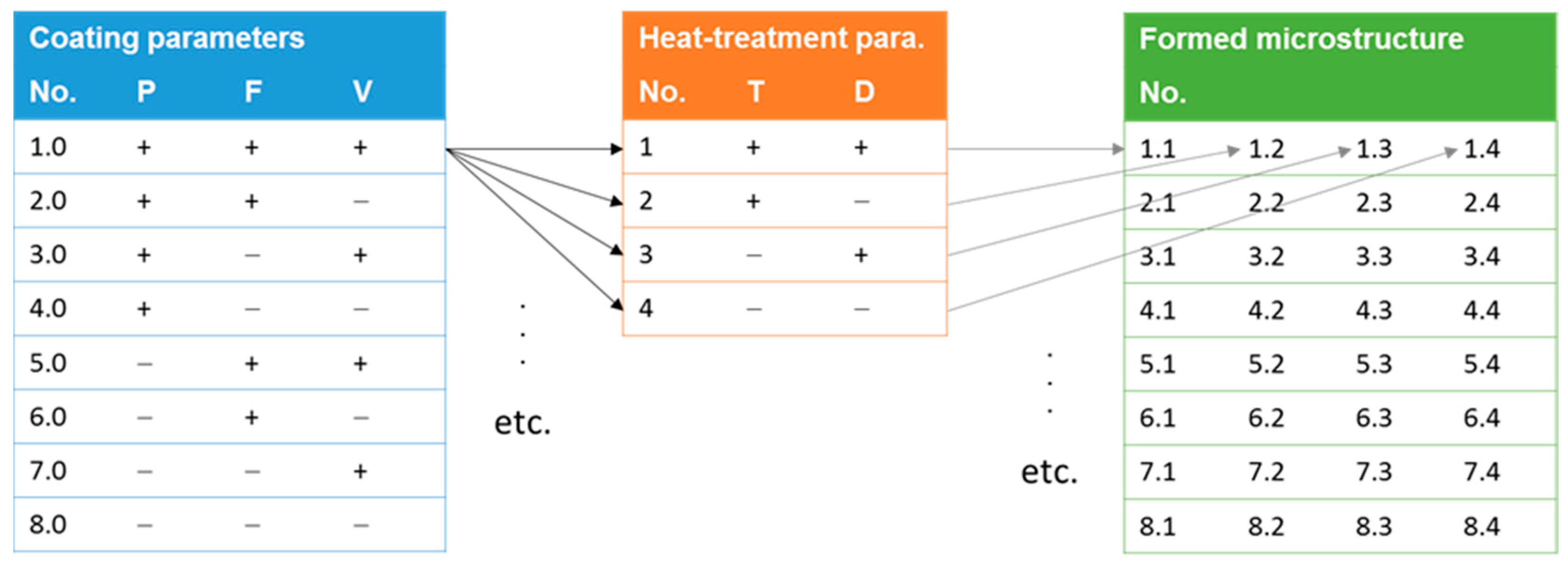
2.4. Design of Experiments

The main objective of the present study was to reduce the pores in the repair coating, especially in the filler metal layer. Given the various parameters that influence microstructural evolution, a design of experiments (DOE) approach was employed. Specifically, five parameters were selected: Powder particle size (P) of the filler metal, powder feed rate (F), traverse velocity (V), brazing temperature (T) and brazing dwell (D). Each of the parameters was assigned a high (+) and a low (−) level value, and this resulted in a 25 = 32 full factorial DOE. The parameters, their units and the highs and lows are shown in Table 3.
The process parameters can be divided into two groups. The first group with the parameters P, F and V can be assigned to the coating, while the parameters T and D refer to the heat-treatment, which is the second group. Due to these two groups of parameter sets, the full factorial DOE can be divided into two sub DOEs. For the coating part, there are 23 = 8 sets and 22 = 4 for the heat-treatment part. Regarding the as-sprayed samples, there is a total number of 40 samples to be investigated. Figure 3 illustrates the DOE.

2.5. Characterization of the Coatings

For the characterization of the samples, metallographic cross sections were prepared. The microstructures of the coated and heat-treated specimens were investigated by light optical and electron microscopy. An Axioplan 2 microscope (Zeiss, Oberkochen, Germany) was used for the light optical microscopic images and a field emitter scanning electron microscope (FE-REM SUPRA 40 VP, Zeiss, Oberkochen, Germany) with an energy dispersive X-ray spectrometer (EDX) was used for the determination of the element distribution within the specimens. The porosity was determined by digital analysis using the software ImageJ [22].

3. Results and Discussion

Figure 4 depicts the analysis of the amount of pores in the filler metal in the state as-sprayed (green columns) and after the combined brazing/aluminizing process (yellow columns). The average porosity in the as-sprayed-state samples is 5.3% ± 0.8%. In the brazed/aluminized samples, the porosity shows larger variation. The highest porosity is 17.6% (sample 1.2), and the lowest porosity is 2.2% (sample 4.3). Nevertheless, most of the porosity is within the range of 2.9% to 6.6%. It is obvious that there are large fluctuations in the porosity when the coarse powder is used (samples 1.1 to 4.4), where the average porosity is 6.0% ± 3.7%. In contrast, the average porosity of the fine powder (sample 5.1 to 8.4) is 4.2% ± 0.8%. The average surface roughness of the samples was Ra = 12.97 µm ± 2.44 µm and Rz = 65.86 µm ± 11.03 µm.
Figure 5 shows cross sections of two representative as-sprayed samples with coarse (Figure 5a) and fine (Figure 5b) filler metal powder along with a higher magnification detail (Figure 5c). Starting from the base material (Inconel 718), the thermally sprayed filler metal (B-Ni5), the hot gas corrosion protective layer and finally the aluminum are marked in the applied order. The boundary between the filler metal and the MCrAlY layer is difficult to recognize but can be observed in a SEM micrograph based on the distribution of the alloying elements (Figure 5d).
This section may be divided by subheadings. It should provide a concise and precise description of the experimental results, their interpretation, as well as the experimental conclusions that can be drawn.
The applied coating with the coarse filler metal powder (Figure 5a) shows a lamellar micro-structure, which is typical for an APS process and is slightly different to the microstructure obtained when using the fine powder. The fine powder particles easily oxidize, and the formed oxides are distributed in the coating, which can be seen in the enlarged section (Figure 5c, dark grey areas). For further discussion of the results, the two cases are considered separately.

3.1. Fine Powder

Figure 6 shows the cross sections of two brazed and aluminized samples, with two extreme sets of parameters where the fine powder was used. In the first set, all parameters have high values (sample 5.1, Figure 6a), whereas in the second set, all the parameters have low values (sample 8.4, Figure 6b).
Compared to Figure 5, on top of the coating a wide grey layer can be seen, which indicates that the β-phase (NiAl) is formed [15]. This is in accordance with the phase diagram Ni-Al [23]. Nevertheless, the filler metal microstructures of the as-sprayed and brazed/aluminized samples do not differ much. The key feature is the formed oxides in the filler metal layer. These oxides reduce the flowability of the filler metal, and thus, the coating parameters as well as the heat treatment parameters do not drastically influence the microstructure of the filler metal.

3.2. Coarse Powder

Figure 7 shows the cross sections of brazed and aluminized samples with identical coating parameters (high values) but with different heat treatment parameters (sample 1.1–1.4). It is obvious that the heat treatment now has an impact on the filler metal’s microstructure. In contrast to the as-sprayed samples and the brazed/aluminized samples using the fine powder, the boundary between the filler metal and the MCrAlY layer can clearly be recognized. On top of the coating, the formed β-Phase (NiAl) is visible. The most prominent feature is the large defects within the coating. Based on the appearance in the micrographs, these should be referred to as voids rather than as porosity. These voids can occur due to segregation effects and diffusion processes. The latter are caused by local differences in concentration. Another effect are volume contractions while the filler metal solidifies.
The filler metal layer contains brighter and darker regions. Depending on the heat treatment parameters these are differently distributed. Figure 8 shows an SEM micrograph of the filler metal layer of sample 1.1 along with the element distribution of nickel, chromium and silicon.
Composition 1 is a nickel phase enriched with silicon, while composition 2 can be identified as a chromium-rich nickel phase. Further, the EDX analysis shows that a minor amount of iron (<1 at%) is present. During the heat treatment, iron from the Inconel 718 base material dissolves into the filler metal and is distributed throughout the filler metal layer. In the ternary Ni-Cr-Si and the binary phase diagram of the system Ni-Si, several solid solutions can be formed [24,25,26]. The silicon rich phase (composition 1) is formed inside the filler metal and can be attributed to the eutectic composition in the binary system Ni-Si [26] and is typical for a conventional standard brazing process. Due to diffusion processes, composition 2 solidifies isothermally and is formed at the boundaries B-Ni5/Inconel 718 and B-Ni5/MCrAlY. This indicates that the remaining liquid part of the filler metal is enriched with silicon until the eutectic composition is reached [27]. A similar state can be observed at samples 1.2 and 1.3, but this is not as pronounced as in sample 1.1. and is attributed to slower diffusion. On the one hand, a shorter brazing dwell (sample 1.2) diminishes the time for diffusion, and on the other hand, a lower temperature reduces the diffusion coefficient (sample 1.3). A shorter brazing dwell and a lower diffusion coefficient led to the microstructure seen in sample 1.4. The boundary region of the isothermally solidified composition 2 is not pronounced very well, and within the boundary regions, the chromium rich and silicon rich phases are distributed equally. Although there are some bonding defects, which are caused by the Kirkendall effect [20], less diffusion activity leads to a microstructure with a reduced amount of pores or voids.
Figure 9 shows the cross sections of brazed and aluminized samples (samples 4.1–4.4). The coating parameters (feed rate and velocity) have low values and the heat treatment parameters vary. In this case, the microstructures of samples 4.1 and 4.2 appear nearly identical and are similar to samples 1.2 and 1.3 but without voids. Samples 4.3 and 4.4 are identical to sample 1.4.
Regarding the set of parameters used for samples 4.1 to 4.4, the heat treatment also influences the filler metal’s microstructure but with smaller impact. The data demonstrate that the temperature is the key parameter that governs the filler metal’s microstructure. Due to a lower temperature, pores or voids can be reduced. Additionally, a lower temperature of the filler metal causes a higher viscosity, so that the flowability of the material is reduced, and thus the segregation and diffusion processes are less pronounced than at higher temperatures. For a homogenous distribution of the different phases in the filler metal, additional to the heat treatment parameters, the coating parameters powder feed rate and traverse velocity must be considered and must be set to low level values. The reason for this phenomenon is not fully clear and has to be investigated in future works.
It should be noted at this point that this DOE is only used to obtain a microstructure with the lowest possible porosity in the brazed joint. Since the void fraction ranges from 2.2% to 17.6%, further evaluation of the DOE in terms of the main effects of the parameters on the average porosity and further interactions of the parameters with each other was not pursued. Figure 10 illustrates this relationship based on the main effects of the parameters F, V, T and t on porosity.
At first glance, changes in F, V and t have a large influence on the porosity, while the influence of T is rather small. However, if the standard deviations of the mean porosity are considered, no statement can be made about the influence of the parameters on the target value within the error limits. Furthermore, diffusion, segregation, dissolution and precipitation processes cannot be covered by this DOE, so that in principle the parameters must be adapted for each material system by setting up a DOE.
The present study has demonstrated that it is possible to carry out a combined brazing/aluminizing process using a dwell typical for standard brazing processes. This new approach has both technological and economic advantages. Especially the expensive and time-consuming conventional aluminizing process, which is usually carried out via pack cementation or in a special aluminizing furnace with a hazardous atmosphere, can be substituted. The developed hybrid technology has also the potential to carry out this repair process in a continuous gas shielding furnace.

4. Conclusions

A combined brazing and aluminizing process for a thermally sprayed repair coating for high pressure turbine blades was analyzed. The coating consisted of the filler metal, the hot gas corrosion protective layer and an aluminum top layer. The focus was on the effect of the spray process parameters and heat treatment on void formation within the coatings. The main results can be summarized as follows:
  • When using fine powder particles (<63 µm) of the filler metal, these oxidize easily, and thus, flowability of the filler metal is reduced.
  • The oxidation of the fine particles dominates the microstructural evolution. In turn, the effect of the heat treatment parameters on microstructure is only minor in this case.
  • For coarser grained powder particles, the effect of oxidation diminishes, and heat treatment starts to have a significant impact on the resulting microstructures.
  • In case of the coarser powder particles, the voids in the coating can be reduced via appropriate selection of heat treatment parameters. Specifically, the voids can be reduced by selecting a lowering brazing temperature and/or shorter dwell periods. This effect can be attributed to diminished diffusion and segregation processes along with the higher viscosity of the filler metal.
  • Powder feed rate and the traverse velocity should be set to low values for obtaining a homogeneous distribution of the formed phases within the brazed seam.

Author Contributions

Conceptualiziation, M.N.; methodology, M.N.; validation, M.N.; K.M.; H.J.M.; investigation, M.N.; writing—original draft preparation, M.N.; writing—review and editing, H.J.M.; visualization, M.N. All authors have read and agreed to the published version of the manuscript.

Funding

Funded by the Deutsche Forschungsgemeinschaft (DFG, German Research Foundation)—Project number 119193472.

Institutional Review Board Statement

Not applicable.

Informed Consent Statement

Not applicable.

Data Availability Statement

Not applicable.

Conflicts of Interest

The authors declare no conflict of interest.

References

  1. Vardelle, A.; Moreau, C.; Akedo, J.; Ashrafizadeh, H.; Berndt, C.C.; Berghaus, J.O.; Boulos, M.; Brogan, J.; Bourtsalas, A.C.; Dolatabadi, A.; et al. The 2016 Thermal Spray Roadmap. J. Therm. Spray Technol. 2016, 25, 1376–1440. [Google Scholar] [CrossRef]
  2. Gérad, B. Application of thermal spraying in the automobile industry. Surf. Coat. Technol. 2006, 201, 2028–2031. [Google Scholar] [CrossRef]
  3. Brand, O.; Möhwald, K.; Reimche, W.; Bruchwald, O. Practical experiences using HVOF sprayed tungsten carbide coatings in the plastic foil industry. In Proceedings of the ITSC 2017 Conference Proceedings, Düsseldorf, Germany, 7–9 June 2017; DVS Media GmbH: Düsseldorf, Germany, 2017; pp. 360–363. [Google Scholar]
  4. Stolle, R. Conventional and Advanced Coatings for Turbine Airfoils, MTU Aero Engines Munich. 2004. Available online: http://www.academia.edu/7789702/Conventional_and_advanced_coatings_for_turbine_airfoils (accessed on 14 January 2021).
  5. Fayomi, O.S.I.; Agboola, O.; Akande, I.G.; Emmanuel, A.O. Challenges of coatings in aerospace, automobile and marine industries. AIP Conf. Proc. 2020, 2307, 020038. [Google Scholar]
  6. Naraparaju, R.; Schulz, U.; Mechnich, P.; Döbber, P.; Seidel, F. Degradation study of 7 wt.% yttria stabilised zirconia (7YSZ) thermal barrier coatings on aero-engine combustion chamber parts due to infiltration by different CaO–MgO–Al2O3–SiO2 variants. Surf. Coat. Technol. 2014, 260, 73–81. [Google Scholar] [CrossRef]
  7. Bakan, E.; Mack, D.E.; Mauer, G.; Vaßen, R.; Lamon, J.; Padture, N.P. High-temperature materials for power generation in gas turbines. In Advanced Ceramics for Energy Conversion and Storage, 1st ed.; Guillon, O., Ed.; Elsevier: Amsterdam, The Netherlands, 2019; pp. 3–62. [Google Scholar]
  8. Huang, X.; Miglietti, W. Wide Gap Braze Repair of Gas Turbine Blades and Vanes—A Review. J. Eng. Gas Turbines Power 2011, 134, 010801. [Google Scholar] [CrossRef]
  9. Henderson, M.B.; Arrell, D.; Larsson, R.; Heobel, M.; Marchant, G. Nickel-based superalloy welding practices for industrial gas turbine applications. Sci. Technol. Weld. Join. 2004, 9, 13–21. [Google Scholar] [CrossRef]
  10. Migletti, W.; Summerside, I. Repair Process Technology Development & Experience For W501F Row 1 Hot Gas Path Blades. In Proceedings of the ASME Turbo Expo 2010: Power for Land, Sea and Air, Glasgow, UK, 14–18 June 2010. [Google Scholar]
  11. Bobzin, K.; Ernst, F.; Rösing, J.; Schlegel, A.; Rojas, Y. Hochtemperaturlöten als Reparaturverfahren zur Erweiterung der Lebensdauer einkristalliner Turbinenkomponenten. Schweißen und Schneiden 2007, 59, 249–252. [Google Scholar]
  12. Laux, B.; Piegert, S.; Rösler, J. Fast epitaxial high temperature brazing of single crystal-line nickel based superalloys. J. Eng. Gas Turbines Power 2009, 131, 032102. [Google Scholar] [CrossRef] [Green Version]
  13. Zhan, Z.; He, Y.; Li, L.; Liu, H.; Dai, Y. Low-temperature formation and oxidation resistance of ultrafine aluminide coatings on Ni-base superalloy. Surf. Coat. Technol. 2009, 203, 2337–2342. [Google Scholar] [CrossRef]
  14. Nicolaus, M.; Rottwinkel, B.; Alfred, I.; Möhwald, K.; Nölke, C.; Kaierle, S.; Maier, H.J.; Wesling, V. Future regeneration processes for high-pressure turbine blades. CEAS Aeronaut. J. 2018, 9, 85–92. [Google Scholar] [CrossRef]
  15. Nicolaus, M.; Möhwald, K.; Maier, H.J. A Combined Brazing and Aluminizing Process for Repairing Turbine Blades by Thermal Spraying Using the Coating System NiCrSi/NiCoCrAlY/Al. J. Therm. Spray Technol. 2017, 26, 1659–1668. [Google Scholar] [CrossRef]
  16. Brooks, J.W.; Bridges, P.J. Metallurgical Stability of Inconel Alloy 718. In Superalloys 1988; The Metallurgical Society, TMS: Pittsburgh, PA, USA, 1988; pp. 33–42. [Google Scholar]
  17. Schirra, J.J. Effect of Heat Treatment Variations on the Hardness and Mechanical Properties of Wrought Inconel 718. In Superalloys 718, 625, 706 and Various Derivatives; The Minerals, Metals & Materials Society, TMS: Pittsburgh, PA, USA, 1991; pp. 431–438. [Google Scholar]
  18. Rao, G.A.; Kumar, M.; Srinivas, M.; Sarma, D.S. Effect of Solution Treatment Temperature on the Microstructure and Tensile Properties of P/M (HIP) Processed Superalloy Inconel 718. In Superalloys 718, 625, 706 and Various Derivatives; The Minerals, Metals & Materials Society, TMS: Pittsburgh, PA, USA, 2001; pp. 605–616. [Google Scholar]
  19. Česnik, D.; Bratuš, V.; Kosec, B.; Rozman, J.; Bizjak, M. Heat treatment and fine-blankin Inconel 718. RMZ Mater. Geoenviron. 2008, 55, 163–172. [Google Scholar]
  20. Nakajima, H. The discovery and acceptance of the Kirkendall Effect: The result of a short research career. JOM 1997, 49, 15–19. [Google Scholar] [CrossRef]
  21. Babiak, Z.; Wenz, T. Grundlagen der thermischen Spritztechnik, Flamm- und Lichtbogenspritzen. In Moderne Beschichtungsverfahren; Bach, F.-W., Möhwald, K., Laarmann, A., Wenz, T., Eds.; Wiley-VCH: Weinheim, Germany, 2006; pp. 131–149. [Google Scholar]
  22. ImageJ. Image Processing and Analysis in Java. Available online: https://imagej.nih.gov/ij/ (accessed on 20 January 2021).
  23. Ansara, I.; Dupin, N.; Lukas, H.L.; Sundman, B. Thermodynamic assessment of the Al-Ni system. J. Alloys Compd. 1997, 247, 20–301. [Google Scholar] [CrossRef]
  24. Gupta, K.P. The Cr-Ni-Si (Chromium-Nickel-Silicon) System. J. Phase Equilibria Diffus. 2006, 27, 523–528. [Google Scholar] [CrossRef]
  25. Schuster, J.C.; Du, Y. Experimental Investigation and Thermodynamic Modeling of the Cr-Ni-Si System. Metall. Mater. Trans. A 2000, 31, 1795–1803. [Google Scholar] [CrossRef]
  26. Nash, P.; Nash, A. The Ni−Si (Nickel-Silicon) system. Bull. Alloy Phase Diagr. 1987, 8, 6–14. [Google Scholar] [CrossRef]
  27. Tung, S.K.; Lim, L.C.; Lai, M.O. Solidification phenomena in nickel base brazes containing boron and silicon. Scr. Mater. 1996, 34, 763–769. [Google Scholar] [CrossRef]
Figure 1. Conventional process chain for repairing turbine blades [10].
Coatings 11 00725 g001
Figure 2. Principle of the coating and joining hybrid technology, recompiled from [15].
Coatings 11 00725 g002
Figure 3. Schematic illustrating the DOE approach employed.
Coatings 11 00725 g003
Figure 4. Porosity in filler metal for different samples in the as-sprayed condition and after the heat-treatment process.
Coatings 11 00725 g004
Figure 5. Optical micrographs and EDX data from cross sections of as-sprayed samples: (a) coarse powder, (b) fine powder, (c) fine powder (enlargement), (d) element distribution (EDX).
Coatings 11 00725 g005
Figure 6. Optical micrographs from cross sections of brazed/aluminized samples (fine powder): (a) parameter set 1, (b) parameter set 2.
Coatings 11 00725 g006
Figure 7. Optical micrographs of cross sections of brazed/aluminized samples (coarse powder; different heat treatment but identical coating parameters).
Coatings 11 00725 g007
Figure 8. SEM micrographs (back-scattered electron detector mode) including element distribution of the filler metal layer.
Coatings 11 00725 g008
Figure 9. Optical micrographs of cross sections of brazed/aluminized samples (coarse powder; different heat treatment, but identical coating parameters).
Coatings 11 00725 g009
Figure 10. Main effects of the parameters F, V, T and t on the average porosity.
Coatings 11 00725 g010
Table 1. Chemical composition (in mass%) of the materials employed.
MaterialInconel 718Ni650 (B-Ni5)MCrAlY
Ni56.571.047.5
Co19.0 23.0
Cr 19.017.0
Si 10.0
Al0.5 12.0
Y 0.5
Fe18.0
Nb + Ta5.1
Ti1.0
Table 2. APS process parameters (Delta torch) used in the thermal spray process.
ParameterValue
Current/A390
Argon flowrate/L·min−140
Hydrogen flowrate/L·min−110
Nozzle distance/mm130
Traverse velocity/m·s−10.9–1.8
Spray angle/°90
Powder size Ni650/µm<106
Powder size MCrAlY/µm−75 + 38
Powder size Al/µm−90 + 45
Powder feed rate/g·min−125–50
Table 3. Process parameters used in the DOE.
ParameterUnitHigh (+)Low (−)
Powder particle sizePµm−106 + 63<63
Powder feed rateFg·min−15025
Traverse velocityVm·s−11.80.9
Brazing temperatureT°C11901090
Brazing dwellDmin155
Publisher’s Note: MDPI stays neutral with regard to jurisdictional claims in published maps and institutional affiliations.

