Article

MOCVD of Noble Metal Film Materials for Medical Implants: Microstructure and Biocompatibility of Ir and Au/Ir Coatings on TiNi

by
Evgeniia S. Vikulova
1,
Ksenya I. Karakovskaya
1,
Tatyana P. Koretskaya
1,
Ilya V. Korolkov
1,2,
Elena V. Chepeleva
3,
Igor P. Asanov
1,
Alphiya R. Tsygankova
1,
Eugene A. Maksimovskii
1,
Ekaterina S. Marchenko
4,
Yuriy A. Lantsukhay
3,
Aleksander A. Zheravin
3 and
Natalya B. Morozova
1,*
1
Nikolaev Institute of Inorganic Chemistry, Siberian Branch, Russian Academy of Sciences, Lavrentiev Ave. 3, 630090 Novosibirsk, Russia
2
Research and Development Department, Kemerovo State University, Krasnaya Str. 6, 650000 Kemerovo, Russia
3
Meshalkin National Medical Research Center, Ministry of Public Health of the Russian Federation, Rechkunovskaya Str. 15, 630055 Novosibirsk, Russia
4
Laboratory for Medical Alloys and Shape Memory Implants, Tomsk State University, 36 Lenin Ave., 634050 Tomsk, Russia
*
Author to whom correspondence should be addressed.
Coatings 2021, 11(6), 638; https://doi.org/10.3390/coatings11060638
Submission received: 11 May 2021 / Revised: 22 May 2021 / Accepted: 24 May 2021 / Published: 27 May 2021

Abstract

:
Noble metals such as Ir, Pt, Au are promising as coatings for metal medical implants to improve biocompatibility and corrosion resistance. Moreover, these coatings can be used as a basis for the further formation of bimetallic hetero-structures with enhanced antibacterial properties. In this work, we develop an approach to obtain such coatings by metal-organic chemical vapor deposition (MOCVD). We have been focused on the formation of Ir coating with developed morphology and subsequent discrete Au coating onto the titanium nickelide (TiNi) implant material. Iridium was deposited in an oxidizing atmosphere from the volatile precursor [Ir(cod)(acac)] (cod = cyclooctadiene-1,5, acac = acetylacetonate-anion). The effects of the deposition temperature (290–350 °C) and amount of introduced oxygen on the composition (Ir, Ir + IrO2) and microstructure of the samples were studied. Hetero-metallic Au/Ir coatings were obtained using [(CH3)2Au(thd)] precursor (thd = dpm = dipivaloylmethanate-anion) at a deposition temperature of 240 °C in the presence of oxygen. To assess the biocompatibility, the toxicity of Ir/TiNi, Au/Ir/TiNi, and uncoated TiNi in relation to human embryonic stem cell line Man-1 was examined after 1, 3, and 5 days of incubation. The results obtained were explained based on the coating microstructures.

1. Introduction

Nowadays titanium nickelide (TiNi) alloy is widely used for the manufacturing of implants and other devices for orthopedics and reconstructive surgery [1,2]. The main reasons for medical application of TiNi are its high biological compatibility and unique properties such as shape memory effect, superelasticity, and high damping capacity. Moreover, the Young’s modulus of TiNi is only three times the elastic modulus of human bone, which is the closest match among the non-biodegradable materials. Such biomechanical properties allow minimizing undesirable reactions caused by high rigidity of the inserted structure, for example necrosis under pressure and slow healing. Therefore, TiNi is recognized as an ideal material for a number of load-devices, for example, compression devices for osteosynthesis [3]. Recently, TiNi implants have shown efficacy in a unique one-step reconstruction of oncological patient postoperative chest defects [4]. The devices combined TiNi details with other metal materials used for implants, for example, Ti6Al4V alloy, or corresponding multi-material structures are also of increasing interest [5,6].
Nevertheless, a special processing or functionalization of the TiNi surface is required to eliminate the infectious complications during implantation, since the native material has no pronounced antibacterial effect [7,8]. In addition, when TiNi implant is operated in the corrosive-dynamic conditions of a biological environment, a gradual release of nickel cations can occur, causing toxic or allergic reactions [1,2,3,7,9]. This process can be prevented through the covering of TiNi surface by materials with high corrosion resistance, among which noble metals (Pt, Ir, Au) are of particular interest. A series of studies, including clinical ones, have shown that the deposition of platinum layers on TiNi wire mesh leads to preventing nickel release, improving biocompatibility and maintaining superelastic and shape memory properties [10,11,12]. Unlike other corrosion-resistant materials, noble metal coatings provide the basis for the creation of hetero-metallic structures with enhanced antibacterial properties [7,13,14]. Such compositions are more effective than silver coatings, which are traditionally used as metal antibacterial agents in the implant coatings [7,15]. Thus, the construction of these type of film materials is an attractive strategy to solve both the above-mention problems of TiNi implants. Since the antibacterial action of such hetero-structures is based on the introduction of Ag as a sacrificial anode, the most effective combinations are Ag/Ir and Ag/Au that are characterized by the maximum potential difference in the galvanic pair. However, in the literature only a few works have described the deposition of Au coatings on TiNi nets to improve their X-ray contrast [16], whereas no information is available toward the deposition of metallic iridium coatings on these substrates.
Herein, we develop the approaches to prepare noble metals coatings on TiNi medical implants. For this purpose, we choose metal-organic chemical vapor deposition (MOCVD) as a precision method that allows obtaining coatings on complex shapes objects. Despite the MOCVD approach typically includes substrate heating, which can cause the deformation, its wide applicability toward TiNi substrates was confirmed through numerous works on the deposition of various types of coatings [17,18,19,20]. In this pioneer work, we have obtained Ir coatings on titanium nickelide and test the possibility of layer-by-layer formation of hetero-metallic film materials (Au/Ir). Our goal was to form the coatings with a developed morphology as preferable for promoting osseointegration [7,21,22]. Therefore, we were interested in the realization of high growth rates when obtaining the bottom iridium layer, and then covered it with a discrete gold film. The primary testing of the biocompatibility of the obtained Ir/Ti and Au/Ir/TiNi samples was carried out in order to determine further directions of the research.

2. Materials and Methods

2.1. Noble Metal Coating Preparation

A volatile iridium precursor, [Ir(cod)(acac)] (cod = cyclooctadiene-1,5, acac = acetylacetonate-anion), was synthesized in the Schlenk apparatus by the interaction of [Ir(cod)Cl]2 (Sigma-Aldrich, Sigma-Aldrich Rus LLC, Moscow, Russia, 97%) with acetylacetone Hacac (Dalchem, Nizhny Novgorod, Russia, 99%) in an alkaline medium [23] according to Scheme 1:
The product was purified by zone sublimation (140 °C, 5 × 10⁻² Torr) with 80% yield. Elemental analysis (CARLO-ERBA-11008, wt.%): for C13H19O2Ir found C, 39.3; H, 4.9, calculated C, 39.1; H, 4.8. Melting point: 155 °C. Saturated vapor pressure is given by the equation ln(p, atm) = 23.03 − 12,817/T (K) in the temperature range 100–150 °C [24].
A volatile gold precursor, [(CH3)2Au(thd)] (thd = dpm = dipivaloylmethanate-anion), was synthesized in two stages according to Scheme 2:
Herein, K[AuCl4] obtained by the interaction between KCl and a solution of H[AuCl4] hydrate (Krastsvetmet, metal content ≥ 47.8%) was used as a metal source, and K(thd) obtained through neutralizing of Hthd (Dalchem, 97%) was used as a ligand source. The product was purified by recrystallization from hexane with 65% yield. Elemental analysis (CARLO-ERBA-11008, wt.%): for C13H25O2Au found C 38.6; H 5.8; calculated C 38.1; H 6.1; melting point: 74 °C. Saturated vapor pressure is given by the equation ln(p, atm) = 36.61 − 15231/T (K) in the temperature range 25–50 °C [25].
MOCVD experiments were carried out in an original vertical reactor with cold walls [26,27], at reduced pressure (1.7–2.1 Torr). About 10 × 10 mm2 wafers of monocrystalline silicon (Si(100), Alga-SW, Novosibirsk, Russia) and titanium nickelide (2 mm thick) were used as substrates. TiNi alloy was obtained in an induction furnace by remelting titanium sponge and nickel [28]. Chemical composition (at.%): Ti = 49.72 ± 0.18, Ni = 50.28 ± 0.18. Wire transformation temperatures: Ms = −60 °C, Mf = −132 °C, As = −22 °C, Af = 40 °C. The resulting ingots were rolled into strips and then were cut to produce the plate substrates.
Iridium coatings were deposited at fixed parameters of mass transfer: source temperature (110 °C, partial pressure of precursor vapor = 0.02 Torr) and carrier gas flow rate (argon, 17 mL/min). The deposition temperature and the flow rate of the reagent gas (oxygen) were varied in the ranges of 290–350 °C and 33–133 mL/min, respectively. Gold was deposited at an evaporator temperature of 70 °C (partial vapor pressure of the precursor = 0.3 Torr), a deposition temperature of 240 °C, argon and oxygen flow rates of 17 mL/min. Growth rates (nm/min) were calculated as the quotients of the coating thicknesses and the deposition times.

2.2. Coating Characterization

The phase composition of the coatings was determined by X-ray diffraction (XRD, Shimadzu XRD-7000 diffractometer, OneSight linear detector, Shimadzu, Kyoto, Japan). The diffraction patterns were recorded with a step of 2θ = 0.0143° and 5 s accumulation per a point on CuKα radiation (Ni filter, range 2θ = 10–65°) or on CoKα radiation (Fe filter, range 2θ = 10–80°). For ease of comparison, the results were converted to CuKα radiation. Diffraction patterns were indexed according to the PDF file [29]. The unit cell parameters of Ir and IrO2 were calculated using the PowderCell 2.4 program [30] with the internal (Si substrate) or external (polycrystalline silicon) standard. The unit cell parameter of Au was calculated from the position of the (111) peak. Coherent scattering regions (CSR) were calculated using the Scherrer formula taking into account the FWHM (full widths at half maximum) of the polycrystalline silicon standard.
The microstructural features of surface and cross-section of the samples were investigated using scanning electron microscopy (SEM, microscope JEOL-ISM 6700F, JEOL, Kyoto, Japan). The elemental composition was estimated by energy dispersive analysis (EDX, analyzer EX-2300BU, JEOL, Tokyo, Japan). EDX detector error was ±5%. The adhesive characteristics of the samples were evaluated using a tape test (adhesive force 2.97 N/10 mm).
Quantitative data on the composition were obtained using X-ray photoelectron spectroscopy (XPS, PHOIBOS-150 spectrometer, SPECS Surface Nano Analysis GmbH, Berlin, Germany, PHOIBOS-150-MCD-9 analyzer, FOCUS-500 monochromator, AlKα radiation, hν = 1486.74 eV, 200 W, analyzer transmission energy 20 eV). The binding energy (Eb) scale was calibrated using the positions of the energy level peaks of the Au 4f7/2 (Eb = 84.0 eV) and Cu 2p3/2 (Eb = 932.67 eV) atoms. To remove the surface layer, the samples were bombarded with Ar+ ions with energy of 2.5 keV for 10 min. The spectra were processed in the CASA program (Japan) using the Doniach-Sanjich asymmetric function. The background was taken into account according to the Shirley method. The Ir 4f spectra are 4f5/2,7/2 doublets with the spin orbit splitting 2.98 eV with the area ratio 4:3. These peaks were fitted into the components using the parameters proposed in [31].
Quantitative data on the amount of deposited gold were obtained by inductively coupled plasma atomic emission spectroscopy (ICP-AES) using the High-Resolution Spectrometer iCAP 6500 (Thermo Fisher Scientific, Waltham, MA, USA). The sample solution was injected into the plasma through a nebulizer of SeaSpray type using a peristaltic pump with the rate of 0.7 mL/min. Analysis conditions: cooling argon flow = 12 L/min, secondary = 0.5 L/min; registration time on the first slit = 15 s; on the second slit = 5 s. The power supplied to ICP inductor was 1150 W (recommended by the manufacturer of the spectrometer). The registration of emission spectra was carried out at the axial observation of plasma.
In the process of sample preparation, the following reagents were used: concentrated nitric and hydrochloric acids of extrapure grade 27-5 and 20-4 (GOST 11125-84, 14261-77), deionized water purified with the Direct-Q3 system (Millipore, Burlington, MA, USA) >18 MΩ/cm; high purity argon; standard solution Au (GSO aurum (1.0 mg/mL) ISO 8429-2003).
Sample dissolution was performed using mixt concentrated hydrochloric and nitric acids (3:1). Sample preparation was performed using disposable plastic tubes with volume of 15 and 50 mL, polypropylene container with volume of 20 mL, and automatic pipette with variable volume (1.00–5.00 mL, 100–1000 μL, 10–100 μL). For determining Au the most intense spectral lines were used (without the spectral influence of the matrix), namely, 208.209, 242.795, 267.595 nm. The validation of technique by spike experiment was provide.

2.3. Biological Investigation

Man-1 cells were provided from the cell culture collection of Laboratory of Developmental epigenetics of the Federal Research Center Institute of Cytology and Genetics SB RAS [32]. The cells were cultured in Dulbecco’s modified Eagle’s medium (DMEM) (Thermo Fisher Scientific, Waltham, MA, USA), supplemented with 10% fetal bovine serum (Thermo Fisher Scientific, Waltham, MA, USA), 100 U/mL penicillin (Gibco, Waltham, MA, USA), 100 U/mL streptomycin (Gibco, Waltham, MA, USA) and 2 mmol/L L-glutamine (Invitrogen, Carlsbad, CA, USA) at 37 °C in a humidified atmosphere of 5% CO2. The cytotoxicity tests were carried out by indirect contact. Extracts were prepared using DMEM medium as the extraction medium with the surface area to extraction medium ratio 1.25 mL/cm2 in a humidified atmosphere with 5% CO2 at 37 °C for 72 h [33]. The control groups involved the use of DMEM medium as negative controls. Cells were incubated in 96-well flat-bottomed cell culture plates at 1 × 10⁴ cells per 200 μL in each well and incubated for 24 h to allow attachment. The medium was then replaced with 200 μL of extracts. After incubating the cells in a humidified atmosphere with 5% CO2 at 37 °C for 1, 3, and 5 days, respectively, cell morphologies were observed by optical microscopy (Nikon Ti-E microscope, Nikon, Tokyo, Japan) and the cytotoxic effect was measured using the Cell Proliferation Kit XTT (Applichem, PanReac Applichem, Barcelona, Spain) according to the manufacturer’s instructions. The optical density of the well contents was measured at a wavelength of 450 nm and a reference wavelength of 655 nm using an iMark plate photometer (Bio-Rad Laboratories, Inc., Hercules, CA, USA) with DMEM medium as a reference solution. Cell viability was calculated using the equation:
Cell   viability   = ( A experimental   group / A control ) × 100 %
where A is the difference between the optical density of the samples and the corresponding reference solution.
The pH in the extracts was measured using pH-meter Anion 4102 with a combined glass electrode ESK-10601/7 (Infraspack-Analit, Novosibirsk, Russia). The electrode was calibrated against a standard buffer solutions with pH 6.86 and 9.18. The content of nickel and other metals in the extracts was determined by ICP-AES as described in par. 2.2 using multielement standard solutions MES 1,2,3,4 [34].

2.4. Statistical Analysis

Statistical processing of the results was carried out using the STATISTICA 8.0 software (StatSoft Inc., Tulsa, OK, USA). Normality of data distribution was assessed using the Shapiro–Wilk test. Mann–Whitney U-test was used to identify differences between groups. Differences between groups were considered significant at p < 0.05. Results are presented as median and interquartile range.

3. Results and Discussion

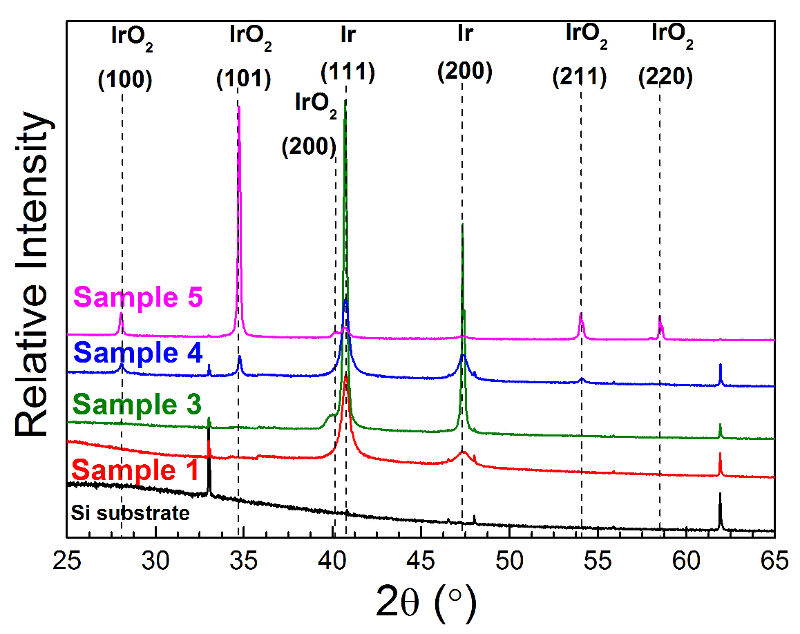
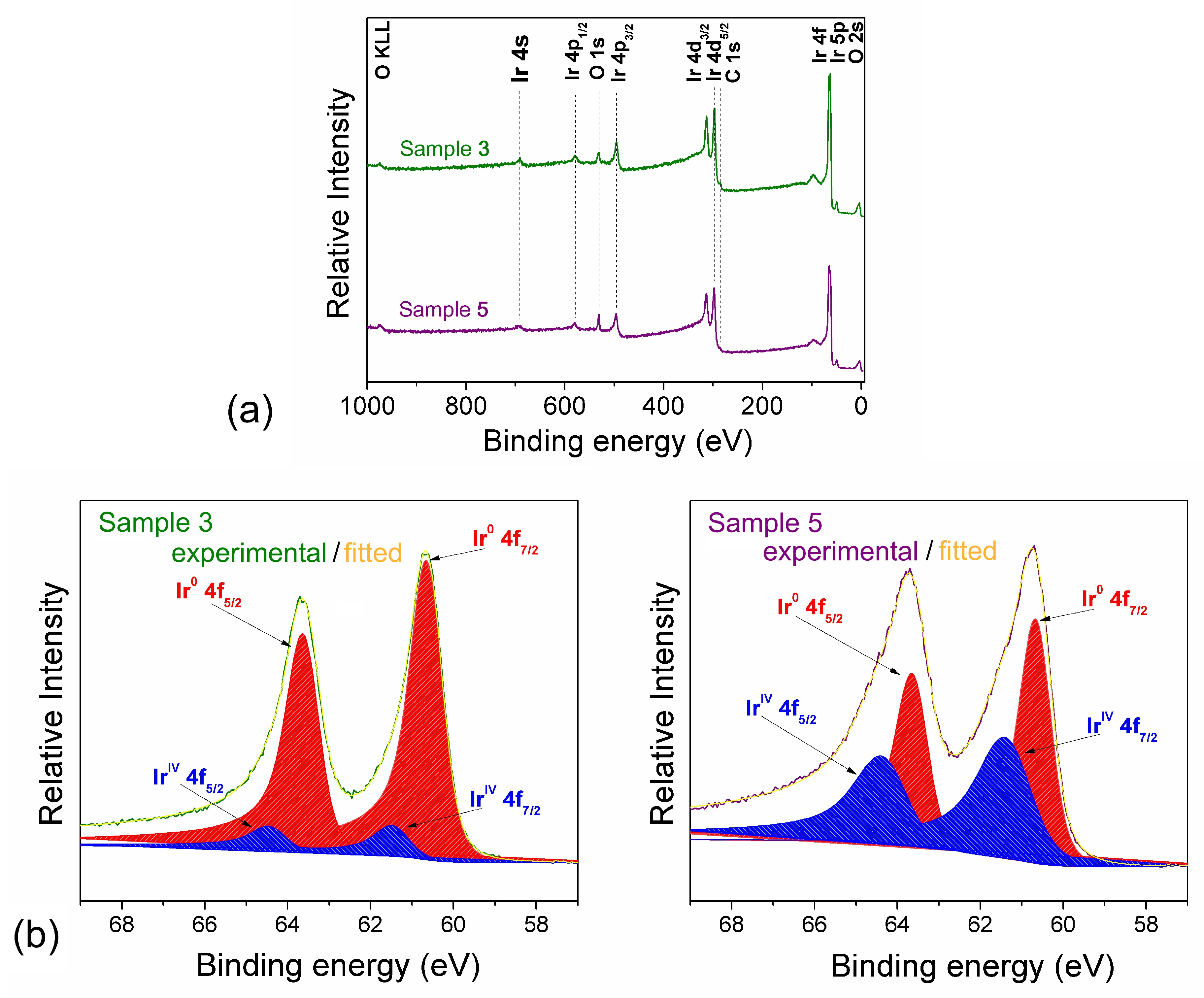
3.1. Composition and Microstructure of Coatings Obtained by MOCVD from [Ir(cod)(acac)] in Oxidizing Atmosphere

Traditionally, metallic iridium coatings have been obtained through the MOCVD in a reducing atmosphere [23,35,36,37]. These experiments should be carried out at relatively high temperatures (≥400 °C) to achieve effective vapor decomposition of most volatile precursors in hydrogen presence. However, lower temperatures (≤350 °C) are recommended to coat TiNi substrates via a MOCVD approach [17,18,19,20]. The use of oxygen as a reagent gas is an opportune way both to reduce the deposition temperature and ensure a high growth rate. However, the process is complicated by the possibility of oxidized iridium formation [35,36]. The studies of thermal decomposition of iridium complexes vapors [38] and MOCVD processes at various oxygen concentrations [39] have demonstrated that the presence of cyclooctadiene-1,5 (cod) as a part of the precursor leads to the formation of the metal phase.
In this work, a complex [Ir(cod)(acac)] characterized by availability and storage stability [40] was selected as the iridium precursor. Since this compound was used only in a reducing atmosphere [23,41], we started the work with a series of MOCVD experiments varying deposition temperature and oxygen flow rate using model Si substrates to study the composition and microstructural features of the coatings obtained. The deposition conditions for the studied samples are shown in Table 1.
The surface of the coatings obtained at a low oxygen flow rate (33 mL/min, samples 1–3) is formed by small particles of an irregular shape (Figure 1a,b). The deposition temperature increasing in the range of 290–350 °C leads to the changes in the size of these particles (from 10–20 nm in sample 1 and 2 to 40–90 nm in sample 3), and their shape converts to the X-shape (sample 3). The smallest particles (samples 1 and 2) are grouped into agglomerates (Figure 1a). The cross-section study has showed that the columnar-dendritic growth of coatings is realized under these MOCVD conditions (Figure 1a,b). At low deposition temperatures (samples 1 and 2), the columnar formations are very densely packed and formed by small pieces close in size to those observed on the surface (Figure 1a). With an increase in the deposition temperature (sample 3), the boundaries of the columnar formations appear more clearly and their width rise in accordance with the growth of their constituent particles (Figure 1b). The two-fold increase in the growth rate was observed when the deposition temperature changed from 290 to 350 °C. In general, the observed columnar-dendritic microstructure is typical for the metallic iridium coatings obtained by MOCVD at high growth rates and low ratios of the deposition temperature (Tdep.) to the melting temperature (Tm) of the metal [37]. In our experiments, this ratio was Tdep./Tm = 0.12–0.14 (Tm(Ir) = 2446 °C [42]).
According to XRD, the investigated coatings are formed by polycrystalline metallic iridium (Table 1). The diffraction patterns contain reflections (111) and (200) of fcc-Ir at 2θ = 40.7° and 47.3°, respectively (Figure 2). The intensity ratio of these reflections I(111)/I(200) is 3.0–6.0, which indicates a slight preferred orientation in the (111) direction (I(111)/I(200) = 2 for randomly oriented crystallites). The average crystallite sizes calculated from CSR correspond to the particle sizes estimated from the SEM data. The unit cell parameter (Table 1) is close to that for pure iridium (3.839 Å, PDF 010-87-0715 [29]). It should be noted that the presence of a small shoulder in the region 2θ = 39.2–40.2° in the diffraction pattern of sample 3 obtained at the highest deposition temperature (350 °C) may indicate the presence of an iridium oxide phase (Figure 2).
An increase in the oxygen flow rate strongly promotes the formation of the oxidized iridium. For example, its four-fold increase is sufficient for the formation of crystalline IrO2 even at a deposition temperature of 310 °C (sample 4, Figure 2). With a two-fold increase, the oxide phase becomes dominant already at 330 °C (sample 5, Figure 2). The strong preferred orientation of IrO2 crystallites along the (101) direction is observed for this sample. The unit cell parameters of iridium oxide calculated here (a = 4.497(2) Å, c = 3.155(3) Å) correspond to pure tetragonal IrO2 (a = 4.505 Å, c = 3.159 Å, PDF 010-88-0288 [29]). According to CSR, the average size of these (101)-oriented crystallites is 130(13) nm and the (110)-oriented crystallites is 85(9) nm.
The appearance of a crystalline oxide phase in the coatings causes corresponding changes in their microstructure. Specifically, three types of particles appear on the surface of the mixed samples: (1) square nanotubes, (2) incomplete/scrolled nanotubes, (3) wedge-shaped rods. The types (1) and (2) are observed in sample 4 with the diameters about 30–50 nm and up to 100 nm, respectively (Figure 1c). The surface of sample 5 is mainly formed by particles (2) with increased sizes (up to 400 nm); particles (3) are also present (Figure 1d). In general, the observed changes in the particle shapes depending on the deposition conditions are consistent with the findings described in the study of the morphology evolution of IrO2 crystals in MOCVD processes using [Ir(cod)(CpMe)] precursor and oxygen reagent gas (CpMe = methylcyclopentadienyl) [43]. An increase in particle size is associated with an increase in the deposition temperature and growth rate.
Samples 3 and 5 were selected for a more detailed investigation of the composition using XPS. The spectra after Ar+ etching are shown in Figure 3a. Both coatings contain only iridium, oxygen, and carbon (wt.%): Ir, 95.1; O, 3.2; C, 1.7 (sample 3); Ir, 93.6; O, 5.3; C, 1.1 (sample 5). The analysis of the Ir 4f peaks shows that in both samples iridium is observed in two states: Ir0 (Eb (Ir 4f7/2) = 60.7 eV) and IrIV belonging to IrO2 (Eb (Ir 4f7/2) = 61.4 eV). It should be noticed that the content of oxidized iridium in sample 5 is significantly higher in comparison with sample 3. Namely, IrO2 is the dominant component in sample 5 (Ir0/IrIV at.% ratio = 0.8). The broadening of the FWHM parameter is observed for the IrIV 4f7/2 component (1.50 compared to 0.90 for the Ir0 component). According to [31], this may indicate the presence of an amorphous oxide. In the case of sample 3, both components of the Ir 4f7/2 peak are close in the considered parameter and its values (FWHM = 0.90 for Ir0 and 0.96 for IrIV) correspond to crystalline phases [31]. The Ir0/IrIV at.% ratio in sample 3 is 6.1. Thus, the general trends in the formation of the sample compositions, determined from the XRD and XPS data, namely an increase in the oxygen content and the predominance of the IrO2 phase in sample 5 compared to 3, correlate with each other. However, to establish correlations of the XPS data with the bulk composition of the resulting coatings, additional studies of the local composition over the layer thickness are required (XPS data are collected in Ir samples from a depth of about 5 nm).

3.2. Iridium and Gold-Iridium Coatings on TiNi

The deposition conditions for sample 2 were selected to obtain metallic Ir coatings on titanium nickelide because here the crystalline oxide phase does not appear yet. However, the growth rate is high enough to provide the developed morphology formed by agglomerates of dendritic columnar structures.
According to SEM and XRD study of the samples obtained in a same experiment on Si and TiNi, the substrate does not affect the microstructure of the forming coating as well as the orientation and the size of the crystallites (Figure 4 and Figure 5a). In particular, the CSR estimated for Ir coatings on TiNi shows sizes of 21(2) nm and 11(1) nm for the crystallites oriented in (111) and (200) directions, respectively. Within the margin of error, this correlates with the data for Ir obtained on Si substrate (Table 1). The relative intensity of the I(111)/I(200) reflections in the coatings on TiNi also varies within 4–5. The unit cell parameter is insignificantly higher than on Si (3.847(2) Å). According to cross-section SEM, the coating thicknesses in this series of samples (Ir/Si) is 680–700 nm. Note that the previous studies of metal coatings on the same TiNi materials have shown that a layer thickness from 400 nm to 2 μm does not prevent superelastic deformation of the substrate [44,45]. Evaluation of the adhesion of the obtained Ir coatings to TiNi by the adhesive tape method (scotch test) showed the absence of peeling.
[(CH3)2Au(thd)] was chosen as a volatile precursor for subsequent deposition of discrete gold film [46]. In the same experiment, Si and TiNi wafers were used as substrates as well as Ir/Si and Ir/TiNi samples described above. The results of studying the obtained samples (Au/Si, Au/TiNi, Au/Ir/Si, and Au/Ir/TiNi) using XRD and SEM are shown in Figure 4 and Figure 5b,c.
According to XRD data, the Au/Si and Au/TiNi samples are characterized by a strong preferred orientation of the fcc-Au phase (Figure 4). In particular, the ratio of the intensities of the (111) (2θ = 38.2°) and (200) (2θ = 44.4°) reflections (I(111)/I(200) is about 400, whereas for a chaotically oriented sample I(111)/I(200) = 2. Moreover, the low intensity of the (200) reflection in comparison with the background in the diffraction pattern of the Au/TiNi sample makes it impossible to calculate CSR. The unit cell parameter of Au calculated from the (111) reflection is 4.076(3) Å, which corresponds to pure gold (4.080 Å, PDF 010-75-6560 [29]). The sizes of Au crystallites oriented in the [111] direction in the samples on Si are larger than in the samples on TiNi, namely 50(5) nm and 35(4) nm, correspondently. Crystallites oriented in the minor direction [100] are characterized by a smaller size (32(3) nm, Au/Si sample).
SEM analysis of the sample surface confirms the similarity of the Au coatings formed on the Si and TiNi surfaces (Figure 5b). In particular, the coating on Si is formed by two types of particles namely nanoparticles with the size of 8–40 nm and irregularly shaped agglomerates up to 400 nm in length. The latter type of particles is preferred. Apparently, these agglomerates are formed by several crystallites. In the case of TiNi, according to the XRD data, a decline in the size of the particles forming the coating surface is observed. The length of the agglomerates does not exceed 200 nm.
The larger type of Au particles is also clearly observed on the surface of the pre-deposited Ir layers on Si and TiNi substrates (Figure 5c). Thus, the formed gold coatings retain the discrete character. XRD analysis allows identifying the fcc-Au (111) and (200) reflexes (Figure 4). The Au texture in the (111) direction noted above is retained, however, it becomes less pronounced: I(111)/I(200) = 4–10. This make it possible to estimate by CSR calculations the sizes of Au crystallites oriented in the (200) direction: 22(2)–28(3) nm. The sizes of Au crystallites oriented in (111) direction are comparable or smaller than those that were formed on TiNi substrate: 28(3)–40(4) nm. The unit cell parameters of Au for Au/Ir/Si and Au/Ir/TiNi samples also corresponds to pure metal indicating the absence of the carbon inclusion in the gold lattice [47,48]. Note that the unit cell parameter and CSR of the Ir phase do not change after Au deposition.
EDX data also confirm the presence of Au in the obtained samples. In particular, the amounts of gold have been evaluated to be 10 at.% and 18 at.% for the samples Au/Ir/Si and Au/Ir/TiNi, respectively. However, the calculation of the elemental composition from the EDX spectra is complicated by the superposition of the CKα (0.277 keV) and AuMα (2.123 keV) bands with iridium bands (N45N67 and Mα, respectively). This can lead to an overestimation of the calculated gold and carbon content. The latter was confirmed by comparing XPS and EDX data for Ir/Si samples. To quantify the deposited gold, we dissolved the obtained coatings in aqua regia and analyzed the resulting solutions by ICP-AES method. The average total gold concentrations were estimated to be 42 and 96 mcg/cm2 for Au/Si and Au/Ir/Si samples, respectively and 56 and 144 mcg/cm2 for Au/TiNi and Au/Ir/TiNi samples, respectively. Thus, the pre-deposited iridium layer favors the deposition of gold in the subsequent MOCVD experiment. Similar effect was observed during electrodeposition of Au nanoparticles on Ir coatings obtained by atomic layer deposition [49]. Is was explained in terms of the additional nucleation centers that formed on the Ir substrate and increase the density of Au islands.

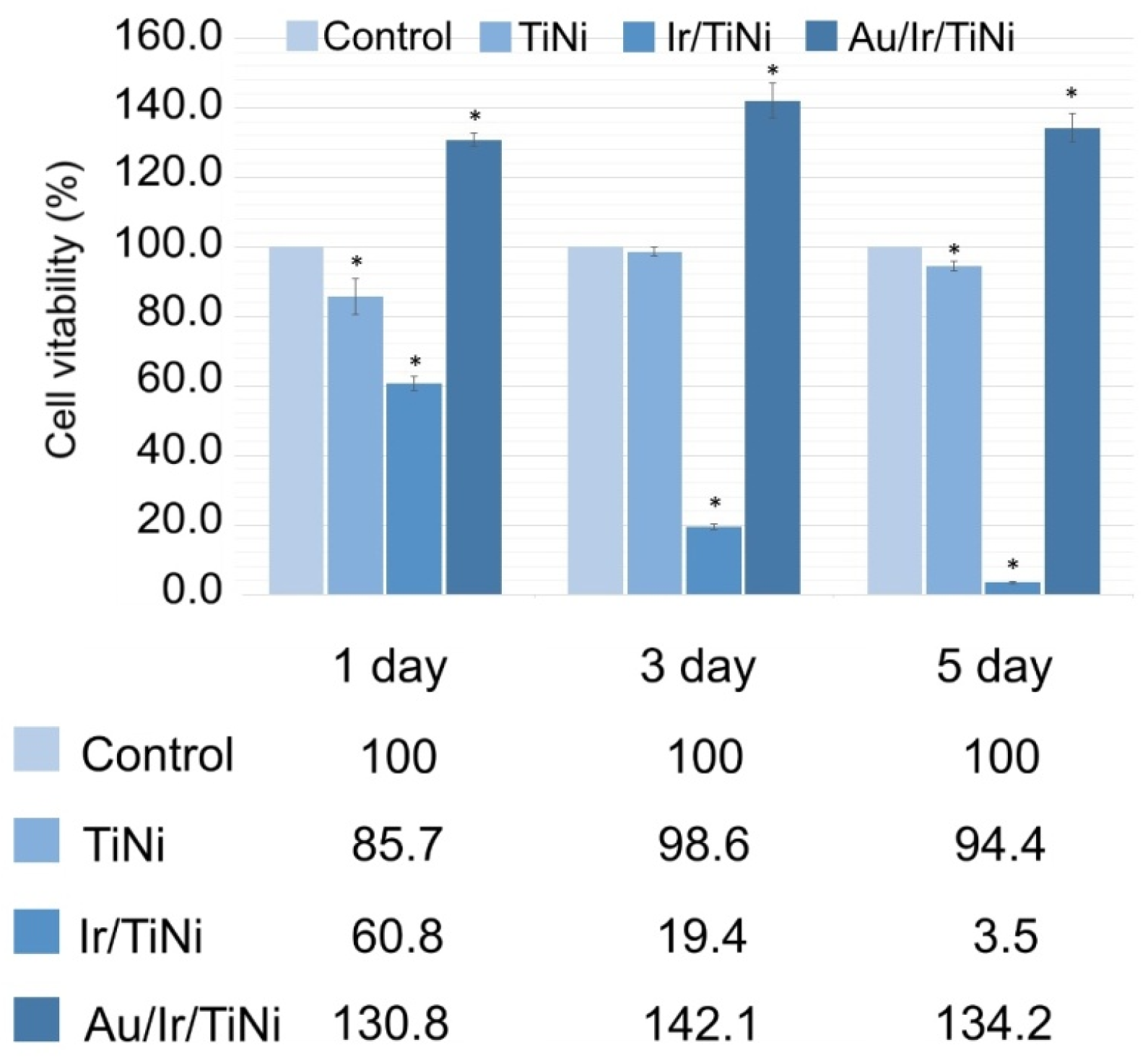
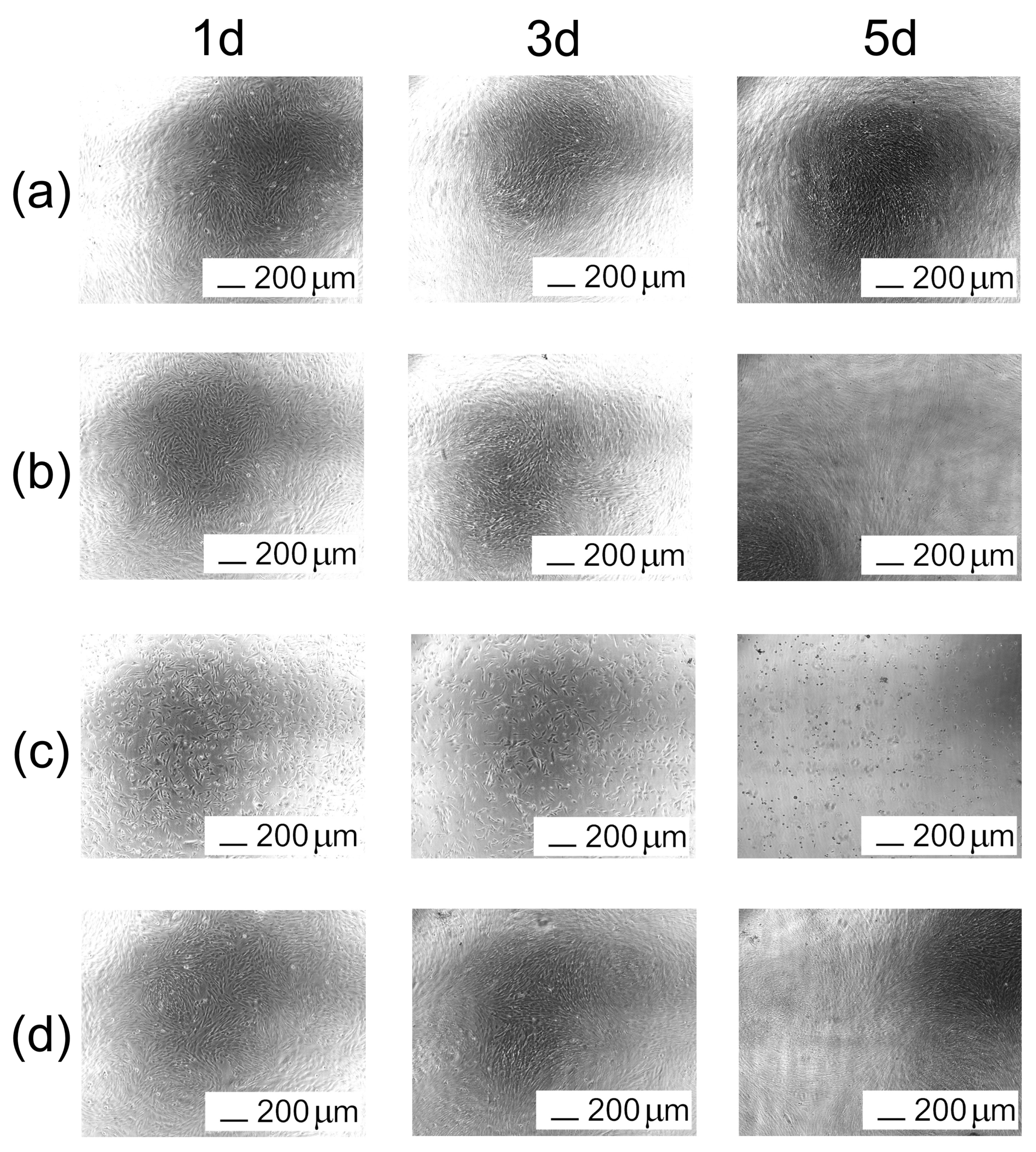
3.3. Biological Characteristics of Noble Metal Coatings on TiNi

To assess the biocompatibility, a series of all-side-coated Ir/TiNi and Au/Ir/TiNi samples were obtained at the conditions discussed in par. 3.2. Human embryonic stem cell line Man-1 [50] were used for primary biological tests. We studied the dynamics of their survival for five days in extracts obtained by keeping the TiNi, Ir/TiNi and Au/Ir/TiNi samples in a culture medium (Figure 6). In the case of uncoated TiNi, in the first 24 h, cell viability was comparable to that observed for control group (86%) and further a trend to a moderate cell proliferation was observed. The extracts obtained using Ir/TiNi samples clearly showed a dynamic cytotoxic effect leading to the death of almost all cells within 5 days. In the case of Au/Ir/TiNi samples, the initial increase in proliferation was observed (up to 130%) and then it was near constant in time.
Figure 7 showed the morphologies of Man-1 cells cultured in extraction media for 1, 3, and 5 days. The cell morphologies in TiNi and Au/Ir/TiNi extracts were normal and healthy, which is similar to that of the control group, and exhibited a healthy morphology of cells with spindle shape. In the Ir/TiNi group, by the end of the first day of observation, the number of living cells decreased markedly, and by the end of the experiment, only a single number remained.
To explain these observations, we performed the analysis of extracts. Measurement of pH showed that all the extracts obtained by keeping the metal samples are close to each other and differ from the control insignificantly. In particular, pH = 7.22 was obtained for control, while in the case of TiNi, Ir/Ti, and Au/Ir/TiNi it was 7.71, 7.58, 7.64, respectively. Thus, there were no negative effect of the medium basicity on cell growth. AES analysis showed that the extracts obtained using the Ir/TiNi samples have a higher nickel content (0.86 mcg/mL). In the case of Au/Ir/TiNi samples, the nickel concentration was an order of magnitude lower (0.096 mcg/mL), while for TiNi samples as well as control extract, no nickel was found. These results correlate with the pronounced cytotoxic effect observed for the Ir/TiNi sample extracts.
The appearance of nickel in the extracts is caused by the electrochemical effect in the Ni-Ir galvanic pair, where Ni becomes a sacrificed anode. The contact of this galvanic pair with the solution that leads to Ni2+ release becomes possible due to the microstructure of the obtained coatings. In fact, the high rate of coating growth in the vertical direction and the defects on the intrinsic TiNi surface relief (Figure 8) lead to the formation of the clearances or cracks between dendrite agglomerates (Figure 8b). Subsequent Au deposition appears to cover these clearances partially (Figure 8c). This prevents Ni release and therefore improves the biocompatibility of the material. The increased proliferation in this case could be associated with the formation of reactive oxidized species (ROSs) promoted by the gold surface. In fact, ROS can stimulate cellular proliferation and act as a second messenger in cellular signaling [51,52]. This issue will be investigated in detail in future work.

4. Conclusions

This work focused on the formation of Ir and Au/Ir coatings with developed morphology onto the TiNi substrates by MOCVD method and the assessment of their biocompatibility.
To obtain target Ir coatings, the [Ir(cod)(acac)] precursor was tested at deposition temperatures 290–350 °C and oxygen flow rates 33–133 mL/min. At lowest oxygen amount, the crystalline metal coatings are mainly formed while the iridium oxide phase appears at higher temperatures (350 °C). The higher oxygen flow (67, 133 mL/min) promotes the formation of a crystalline IrO2 even at lower temperatures. Ir coatings with a well-developed surface morphology formed by dendritic columns of 10–20 nm particles were obtained on TiNi substrates at 310 °C. The surface of these samples was decorated with discrete Au coatings using [(CH3)2Au(thd)] precursor at deposition temperature 240 °C and oxygen flow rate 17 mL/min.
The Ir/TiNi samples exhibited a pronounced cytotoxic effect on Man-1 fibroblasts, which is associated with the nickel release due to the clearances between dendrite agglomerates. The subsequent discrete Au layer reduces nickel leaching and promotes cell proliferation. Therefore, it is of interest to further develop such bimetallic coatings and study their mechanical characteristics.
Alternatively, the development of a sub-layer layer with a compact microstructure could be a further research direction to permit the deposition of noble metal coatings with developed morphologies onto TiNi by MOCVD. It should be also noted that the materials obtained here could be applied directly to other implant materials such as carbon and polymer ones.

Author Contributions

E.S.V.—conceptualization, writing—original draft preparation, validation; K.I.K.—investigation (precursor synthesis and identification, coating characterization), writing—original draft preparation, visualization; T.P.K.—investigation (MOCVD experiments); I.V.K.—investigation (powder XRD); I.P.A.—investigation (XPS); E.V.C.—investigation (biological properties); A.R.T.—investigation (ICP-AES analysis); E.A.M.—investigation (SEM, EDX); E.S.M.—resources, writing—review and editing; Y.A.L.—writing—review and editing; A.A.Z.—writing—review and editing, funding acquisition, project administration; N.B.M.—conceptualization, writing—review and editing, supervision. All authors have read and agreed to the published version of the manuscript.

Funding

This work was financially supported by RFBR (Grant No. 19-415-540012 r_a).

Institutional Review Board Statement

The study was conducted according to the guidelines of the Declaration of Helsinki, and approved by the by the Scientific Ethics Committee of Research Institute of Medical Genetics, Tomsk NRMC (protocol number 106; 27 June 2017).

Informed Consent Statement

Not applicable.

Data Availability Statement

The data presented in this study are available herein.

Conflicts of Interest

The authors declare no conflict of interest.

References

  1. Shabalovskaya, S.; Anderegg, J.; Van Humbeeck, J. Critical overview of nitinol surfaces and their modifications for medical applications. Acta Biomater. 2008, 4, 447–467. [Google Scholar] [CrossRef] [PubMed]
  2. Wadood, A. Brief overview on nitinol as biomaterial. Adv. Mater. Sci. Eng. 2016, 4, 1–9. [Google Scholar] [CrossRef] [Green Version]
  3. Vasudevan, H.; Kottur, V.K.N.; Raina, A.A. Proceedings of International Conference on Intelligent Manufacturing and Automation; Springer Nature: Basingstoke, UK, 2020. [Google Scholar]
  4. Ivanov, V.E.; Kurilchik, A.A.; Ragulin, Y.A.; Zheravin, A.A.; Starodubtsev, A.L.; Zubarev, A.L. Multimodality therapy for osteosarcoma of the sternum with reconstruction of complex chest wal defects. Sib. J. Oncol. 2017, 16, 96–102. [Google Scholar] [CrossRef] [Green Version]
  5. Rehman, A.U.; Babu, N.K.; Talari, M.K.; Usmani, Y.S.; Al-Khalefah, H. Microstructure and mechanical properties of dissimilar friction welding Ti-6Al-4V alloy to nitinol. Metals 2021, 11, 109. [Google Scholar] [CrossRef]
  6. Bartolomeu, F.; Costa, M.M.; Alves, N.; Miranda, G.; Silva, F.S. Additive manufacturing of NiTi-Ti6Al4V multi-material cellular structures targeting orthopedic implants. Opt. Lasers Eng. 2020, 134, 106208. [Google Scholar] [CrossRef]
  7. Basova, T.V.; Vikulova, E.S.; Dorovskikh, S.I.; Hassan, A.; Morozova, N.B. The use of noble metal coatings and nanoparticles for the modification of medical implant materials. Mater. Des. 2021, 204, 109672. [Google Scholar] [CrossRef]
  8. Kaur, M.; Singh, K. Review on titanium and titanium based alloys as biomaterials for orthopaedic applications. Mater. Sci. Eng. C 2019, 102, 844–862. [Google Scholar] [CrossRef] [PubMed]
  9. Kwok, D.T.; Schulz, M.; Hu, T.; Chu, C.; Chu, P. Surface treatments of nearly equiatomic NiTi Alloy (nitinol) for surgical implants. Biomed. Eng. Trends Mater. Sci. 2011, 269, 282. [Google Scholar] [CrossRef] [Green Version]
  10. Lertsapcharoen, P.; Apichai, K.; Vidhavas, L.; Pentip, S.; Phingphol, C. Self-expanding nanoplatinum-coated nitinol devices for atrial septal defect and patent ductus arteriosus closure: A swine model. Indian Heart J. 2006, 58, 315–320. [Google Scholar] [PubMed]
  11. Lertsapcharoen, P.; Khongphatthanayothin, A.; Srimahachota, S.; Leelanukrom, R. Self-expanding platinum-coated nitinol devices for transcatheter closure of atrial septal defect: Prevention of nickel release. J. Invasive Cardiol. 2008, 20, 279–283. [Google Scholar] [PubMed]
  12. Lertsapcharoen, P.; Khongphatthanayothin, A.; La-Orkhun, V.; Vithessonthi, K.; Srimahachota, S. Transcatheter closure of patent ductus arteriosus with a self-expanding platinum-coated nitinol device. J. Invasive Cardiol. 2009, 21, 286–289. [Google Scholar]
  13. Köller, M.; Sengstock, C.; Motemani, Y.; Khare, C.; Buenconsejo, P.J.S.; Geukes, J.; Schildhauer, T.A.; Ludwig, A. Antibacterial activity of microstructured Ag/Au sacrificial anode thin films. Mater. Sci. Eng. C 2015, 46, 276–280. [Google Scholar] [CrossRef]
  14. Abuayyash, A.; Ziegler, N.; Gessmann, J.; Sengstock, C.; Schildhauer, T.A.; Ludwig, A.; Köller, M. Antibacterial efficacy of sacrifical anode thin films combining silver with platinum group elements within a bacteria-containing human plasma clot. Adv. Eng. Mater. 2017, 20, 1–5. [Google Scholar] [CrossRef]
  15. Schmidt-Braekling, T.; Streitbuerger, A.; Gosheger, G.; Boettner, F.; Nottrott, M.; Ahrens, H.; Dieckmann, R.; Guder, W.; Andreou, D.; Hauschild, G.; et al. Silver-coated megaprostheses: Review of the literature. Eur. J. Orthop. Surg. Traumatol. 2017, 27, 483–489. [Google Scholar] [CrossRef] [PubMed]
  16. Steegmueller, R.; Wagner, C.; Fleckenstein, T.; Schuessler, A. Gold coating of nitinol devices for medical applications. Mater. Sci. Forum 2002, 394, 161–164. [Google Scholar] [CrossRef]
  17. Tripi, T.R.; Bonaccorso, A.; Condorelli, G.G. Fabrication of hard coatings on NiTi instruments. J. Endod. 2003, 29, 132–134. [Google Scholar] [CrossRef]
  18. Li, J.; Wang, G.; Geng, H.; Zhu, H.; Zhang, M.; Di, Z.; Liu, X.; Chu, P.K.; Wang, X. CVD growth of graphene on NiTi alloy for enhanced biological activity. ACS Appl. Mater. Interfaces 2015, 7, 19876–19881. [Google Scholar] [CrossRef]
  19. Wang, F.; Zhang, Y.; Chen, X.; Leng, B.; Guo, X.; Zhang, T. ALD mediated heparin grafting on nitinol for self-expanded carotid stents. Colloids Surf. B Biointerfaces 2016, 143, 390–398. [Google Scholar] [CrossRef] [PubMed]
  20. Vokoun, D.; Klimša, L.; Vetushka, A.; Duchoň, J.; Racek, J.; Drahokoupil, J.; Kopeček, J.; Yu, Y.S.; Koothan, N.; Kei, C.C. Al2O3 and Pt atomic layer deposition for surface modification of NiTi shape memory films. Coatings 2020, 10, 746. [Google Scholar] [CrossRef]
  21. Liu, Y.; Rath, B.; Tingart, M.; Eschweiler, J. Role of implants surface modification in osseointegration: A systematic review. J. Biomed. Mater. Res. Part A 2020, 108, 470–484. [Google Scholar] [CrossRef] [PubMed] [Green Version]
  22. Novaes, A.B.; de Souza, S.L.S.; de Barros, R.R.M.; Pereira, K.K.Y.; Iezzi, G.; Piattelli, A. Influence of implant surfaces on osseointegration. Braz. Dent. J. 2010, 21, 471–481. [Google Scholar] [CrossRef]
  23. Lozanov, V.V.; Il’in, I.Y.; Morozova, N.B.; Trubin, S.V.; Baklanova, N.I. Chemical vapor deposition of an iridium phase on hafnium carbide and tantalum carbide. Russ. J. Inorg. Chem. 2020, 65, 1781–1788. [Google Scholar] [CrossRef]
  24. Vikulova, E.S.; Karakovskaya, K.I.; Ilyin, I.Y.; Zelenina, L.N.; Sysoev, S.V.; Morozova, N.B. Thermodynamic study of volatile iridium (I) complexes with 1,5-cyclooctadiene and acetylacetonato derivatives: Effect of (O,O) and (O,N) coordination sites. J. Chem. Thermodyn. 2019, 133, 194–201. [Google Scholar] [CrossRef]
  25. Basova, T.V.; Hassan, A.; Morozova, N.B. Chemistry of gold(I, III) complexes with organic ligands as potential MOCVD precursors for fabrication of thin metallic films and nanoparticles. Coord. Chem. Rev. 2019, 380, 58–82. [Google Scholar] [CrossRef] [Green Version]
  26. Dorovskikh, S.I.; Klyamer, D.D.; Koretskaya, T.P.; Kal′nyi, D.B.; Morozova, N.B. Studying the microstructure of pt layers prepared by chemical vapor deposition in the presence of hydrogen. J. Struct. Chem. 2020, 61, 1211–1218. [Google Scholar] [CrossRef]
  27. Krisyuk, V.V.; kyzy, S.U.; Rybalova, T.V.; Korolkov, I.V.; Sysoev, S.V.; Koretskaya, T.P.; Kuchumov, B.M.; Turgambaeva, A.E. Volatile trinuclear heterometallic beta-diketonates: Structure and thermal properties related to the chemical vapor deposition of composite thin films. Polyhedron 2020, 191, 114806. [Google Scholar] [CrossRef]
  28. Gunther, V.; Marchenko, E.; Chekalkin, T.; Baigonakova, G.; Kang, J.H.; Kim, J.S.; Klopotov, A. Study of structural phase transitions in quinary TiNi(MoFeAg)-based alloys. Mater. Res. Express 2017, 4, 105702. [Google Scholar] [CrossRef]
  29. Powder Diffraction File; release 2010; International Centre for Diffraction Data: Newtown Square, PA, USA, 2010.
  30. Kraus, W.; Nolze, G. PowderCell—A program for the representation and manipulation of crystal structures and calculation of the resulting X-ray powder patterns. J. Appl. Crystallogr. 1996, 29, 301–303. [Google Scholar] [CrossRef]
  31. Pfeifer, V.; Jones, T.E.; Velasco Vélez, J.J.; Massué, C.; Arrigo, R.; Teschner, D.; Girgsdies, F.; Scherzer, M.; Greiner, M.T.; Allan, J.; et al. The electronic structure of iridium and its oxides. Surf. Interface Anal. 2016, 48, 261–273. [Google Scholar] [CrossRef] [Green Version]
  32. Grigor'eva, E.V.; Malankhanova, T.B.; Surumbayeva, A.; Pavlova, S.V.; Minina, J.M.; Kizilova, E.A.; Suldina, L.A.; Morozova, K.N.; Kiseleva, E.; Sorokoumov, E.D.; et al. Generation of GABAergic striatal neurons by a novel iPSC differentiation protocol enabling scalability and cryopreservation of progenitor cells. Cytotechnology 2020, 72, 649–663. [Google Scholar] [CrossRef]
  33. Zhang, B.; Hou, Y.; Wang, X.; Wang, Y.; Geng, L. Mechanical properties, degradation performance and cytotoxicity of Mg-Zn-Ca biomedical alloys with different compositions. Mater. Sci. Eng. C 2011, 31, 1667–1673. [Google Scholar] [CrossRef]
  34. Medvedev, N.S.; Shaverina, A.V.; Tsygankova, A.R.; Saprykin, A.I. Analysis of high-purity germanium dioxide by ETV-ICP-AES with preliminary concentration of trace elements. Talanta 2016, 155, 358–362. [Google Scholar] [CrossRef] [PubMed]
  35. Garcia, J.R.V.; Goto, T. Chemical vapor deposition of iridium, platinum, rhodium and palladium. Mater. Trans. 2003, 44, 1717–1728. [Google Scholar] [CrossRef] [Green Version]
  36. Vasilyev, V.Y.; Morozova, N.B.; Basova, T.V.; Igumenov, I.K.; Hassan, A. Chemical vapour deposition of Ir-based coatings: Chemistry, processes and applications. RSC Adv. 2015, 5, 32034–32063. [Google Scholar] [CrossRef]
  37. Yang, S.; Yu, X.; Tan, C.; Wang, Y.; Ma, H.; Liu, K.; Cai, H. Growth kinetics and microstructure of MOCVD iridium coating from iridium(III) acetylacetonate with hydrogen. Appl. Surf. Sci. 2015, 329, 248–255. [Google Scholar] [CrossRef]
  38. Morozova, N.B.; Gelfond, N.V.; Semyannikov, P.P.; Trubin, S.V.; Igumenov, I.K.; Gimeno-Fabra, L. Thermal properties of Ir(I) precupsors: Acetylacetonato(1,5-cyclooctadiene)iridium(I) and (methylcyclopentadienyl)(1,5-cyclooctadiene)itidium (I). Electrochem. Soc. Proc. 2003, 8, 120–125. [Google Scholar]
  39. Kawano, K.; Takamori, M.; Yamakawa, T.; Watari, S.; Fujisawa, H.; Shimizu, M.; Niu, H.; Oshima, N. A novel iridium precursor for MOCVD. Mater. Res. Soc. Symp. Proc. 2003, 784, 145–150. [Google Scholar] [CrossRef] [Green Version]
  40. Karakovskaya, K.I.; Dorovskikh, S.I.; Vikulova, E.S.; Ilyin, I.Y.; Zherikova, K.V.; Basova, T.V.; Morozova, N.B. Volatile iridium and platinum MOCVD precursors: Chemistry, thermal properties, materials and prospects for their application in medicine. Coatings 2021, 11, 78. [Google Scholar] [CrossRef]
  41. Papke, J.A.; Stevenson, R.D. Evaluation of metal-organic compounds as materials for chemical vapor deposition. In Proceedings of the Conference on Chemical Vapor Deposition of Refractory Metals, Alloys, and Compounds, Gatlinburg, TN, USA, 12–14 September 1967. [Google Scholar]
  42. Vanýsek, P. Handbook of Chemistry and Physics, 81th ed.; Electrochemical Series; CRC Press LLC: Boston, MA, USA, 2000. [Google Scholar]
  43. Chen, R.S.; Chang, H.M.; Huang, Y.S.; Tsai, D.S.; Chiu, K.C. Morphological evolution of the self-assembled IrO2 one-dimensional nanocrystals. Nanotechnology 2005, 16, 93–97. [Google Scholar] [CrossRef]
  44. Marchenko, E.; Baigonakova, G.; Yasenchuk, Y. Gradient crystalline coating on a biomedical TiNi alloy prepared by magnetron sputtering and annealing. Vacuum 2020, 181, 109652. [Google Scholar] [CrossRef]
  45. Marchenko, E.S.; Baigonakova, G.A.; Dubovikov, K.M.; Yasenchuk, Y.F.; Gunther, S.V. Reaction synthesis of gradient coatings by annealing of three-layer Ti–Ni–Ti nanolaminate magnetron sputtered on the TiNi substrate. Surf. Interfaces 2021, 24, 101111. [Google Scholar] [CrossRef]
  46. Parkhomenko, R.G.; Morozova, N.B.; Zharkova, G.I.; Shubin, Y.V.; Trubin, S.V.; Kriventsov, V.V.; Kuchumov, B.M.; Koretskaya, T.P.; Igumenov, I.K. Deposition of au thin films and nanoparticles by MOCVD. Chem. Vap. Depos. 2012, 18, 336–342. [Google Scholar] [CrossRef]
  47. Holt, L.; Stanyer, J. Carbon inclusion in gold electroplate. Trans. IMF 1972, 50, 24–27. [Google Scholar] [CrossRef]
  48. Okinaka, Y. Significance of inclusions in electroplated gold films for electronics applications. Gold Bull. 2000, 33, 117–127. [Google Scholar] [CrossRef] [Green Version]
  49. Lim, Y.H.; Yoo, H.; Choi, B.H.; Lee, J.H.; Lee, H.-N.; Lee, H.K. Atomic-layer-deposited Ir thin film as a novel diffusion barrier layer in Cu interconnection. Phys. Status Solidi C 2011, 8, 891–894. [Google Scholar] [CrossRef]
  50. Camarasa, M.V.; Kerr, R.W.; Sneddon, S.F.; Bates, N.; Shaw, L.; Oldershaw, R.A.; Small, F.; Baxter, M.A.; McKay, T.R.; Brison, D.R.; et al. Derivation of Man-1 and Man-2 research grade human embryonic stem cell lines. Vitr. Cell. Dev. Biol. Anim. 2010, 46, 386–394. [Google Scholar] [CrossRef] [PubMed]
  51. Han, M.J.; Kim, B.Y.; Yoon, S.O.; Chung, A.S. Cell proliferation induced by reactive oxygen species is mediated via mitogen-activated protein kinase in Chinese hamster lung fibroblast (V79) cells. Mol. Cells 2003, 15, 94–101. [Google Scholar] [PubMed]
  52. Saxena, S.; Vekaria, H.; Sullivan, P.G.; Seifert, A.W. Connective tissue fibroblasts from highly regenerative mammals are refractory to ROS-induced cellular senescence. Nat. Commun. 2019, 10, 4400. [Google Scholar] [CrossRef] [PubMed] [Green Version]
Scheme 1. Chemical reaction formula for synthesis of [Ir(cod)(acac)].
Coatings 11 00638 sch001
Scheme 2. Chemical reaction formula for synthesis of [(CH3)2Au(thd)].
Coatings 11 00638 sch002
Figure 1. SEM micrographs of the surface (on left) and cross-section (on right) of iridium coatings on Si(100), samples 1 (a), 3 (b), 4 (c), 5 (d); magnification 50,000 times.
Coatings 11 00638 g001
Figure 2. Diffraction patterns of iridium coatings on Si (100).
Coatings 11 00638 g002
Figure 3. XPS spectra of the iridium coatings on Si(100) after etching with Ar+ (a); fitting of Ir 4f spectra into the Ir0 and IrIV components (b).
Coatings 11 00638 g003
Figure 4. Diffraction patterns of Ir, Au, and Au/Ir samples deposited in the same MOCVD experiments on (a) Si; (b) TiNi.
Coatings 11 00638 g004
Figure 5. SEM micrographs of the surface of (a) Ir, (b) Au, and (c) Au/Ir samples deposited on Si and TiNi in the same MOCVD experiments (a—Ir deposition and b,c—Au deposition); magnification 50,000 times.
Coatings 11 00638 g005
Figure 6. Viability of Man-1 cells cultured for 1, 3 and 5 days in 100% extraction medium obtained using TiNi, Ir/TiNi, and Au/Ir/TiNi samples. * p < 0.05.
Coatings 11 00638 g006
Figure 7. Morphologies of Man-1 cells cultured in the extraction media for 1, 3 and 5 days: (a) control, (b) TiNi, (c) Ir/TiNi, (d) Au/Ir/TiNi.
Coatings 11 00638 g007
Figure 8. SEM micrographs of the surface defects of TiNi (a), Ir/TiNi (b), and Au/Ir/TiNi (c) samples.
Coatings 11 00638 g008
Table 1. Deposition conditions, growth rate, and results of XRD study of samples of iridium coatings on Si (100).
No.Tdep., (°C)v(O2), (mL/min)Growth Rate, (nm/min)CompositionIr Unit Cell Parameter, (nm)Ir Average
Crystallite Size (CSR), (nm)
(111)(200)
1290336.0Ir3.849(2)20(2)9(1)
2310338.5Ir3.837(2)23(2)10(1)
33503312.7Ir 13.839(2)73(7)84(9)
431013311.7Ir + IrO23.840(2)22(2)11(1)
53306720.4IrO2 + Ir3.841(2)26(3)19(2)
1 The shoulder in the region 2θ = 39.2–40.2° was observed, which can be attributed to the (200) reflection of tetragonal IrO2.
Publisher’s Note: MDPI stays neutral with regard to jurisdictional claims in published maps and institutional affiliations.

