Article

Effect of Current Density on the Wear Resistance of Ni–P Alloy Coating Prepared through Immersion-Assisted Jet-Electrodeposition

College of Engineering, Nanjing Agricultural University, Nanjing 210031, China
*
Author to whom correspondence should be addressed.
Coatings 2021, 11(5), 527; https://doi.org/10.3390/coatings11050527
Submission received: 14 April 2021 / Revised: 27 April 2021 / Accepted: 27 April 2021 / Published: 29 April 2021
(This article belongs to the Section Corrosion, Wear and Erosion)

Abstract

:
To improve the wear resistance of 45 steel surfaces, a Ni−P alloy coating was prepared on the surface of 45 steel with an immersion-assisted jet-electrodeposition technology. Scanning electron microscopy, energy dispersive spectrometry, X-ray diffraction and confocal microscopy were used in testing the surface morphology, composition, structure, grain size, and wear scar parameters of the coating. The effect of immersion-assisted jet-electrodeposition on the wear resistance of Ni−P alloy coating at current densities of 20–60 A·cm−2 were explored and analyzed. Results showed that the surface quality, microhardness, and wear resistance of Ni−P alloy coatings prepared through immersion-assisted jet-electrodeposition were improved compared with those of the coatings prepared through traditional jet-electrodeposition. With the increase in the current density, the surface cell structure of the alloy coating was refined, the flatness was improved, the surface Ni content was increased, the grain size was refined, and the coating thickness, the microhardness, and wear resistance showed a trend of first increasing and then decreasing. The best surface quality of the coating was observed at a current density of 50 A·cm−2. Moreover, the unit cell structure was obvious, the surface was flat and dense, the coating thickness was the largest, reaching 21.42 μm, the highest Ni content was obtained (98.25 wt.%), the smallest grain size (6.6 nm) was obtained, the microhardness of the coating reached a maximum value (725.58 HV0.1), and the best wear resistance was observed.

1. Introduction

Owing to the rapid development of modern industry, various industries have proposed high requirements for the performance and service lives of mechanical parts. Preparing a coating on the surface of a metal workpiece is one of the important methods used to improve the physical and chemical performance of a substrate and extend its service life. Electrodeposited coatings are currently used in preparing coatings and improving substrate performance, having the advantages of high limiting current density and fast deposition rates. The conditions for electrochemical deposition are the main factors that determine the performance of coatings, such as the current density and electrodeposition methods [1,2,3,4]. Jiang et al. [5] found that the surface defects of Ni−SiC coatings prepared through magnetic field-assisted jet-electrodeposition were reduced relative to those in Ni−SiC coatings prepared through ordinary jet-electrodeposition, and flatness was improved. Xue et al. [6] studied the effect of different electrodeposition methods on the tribological properties of Ni−CeO2 nanocomposite coatings. Hessam et al. [7] found that thin hematite films with good morphology, small grain size, and high bandgaps could be deposited by increasing the current density during electrodeposition. Shourije et al. [8] observed the excellent surface properties of a co-deposited nano-Ni-MoS2 composite coating at a current density of 5 A·dm−2.
Jet-electrodeposition is a local high-speed electrodeposition technique. It creates voltage between the anode and cathode by connecting to a power source. A plating solution is sprayed onto the surface of the cathode workpiece at a high flow rate through the anode nozzle to form a closed loop. The ion deposition process is realized under the action of a strong electric field. Compared with traditional electrodeposition, jet-electrodeposition accelerates the transport of electrodeposition materials and increases the limit current density, thereby accelerating the speed of ion deposition. Under the impact of the plating solution, the thickness of the surface diffusion layer is effectively reduced, and the excessive growth of the crystal grains in the vertical direction is suppressed; thus, a dense plating layer structure and refined crystal grains are obtained [9,10,11,12,13,14]. Compared with a pure Ni coating, a Ni−P alloy coating has excellent physical, chemical, and mechanical properties, and is an alternative to pure Ni coating as an ideal metal substrate protection layer. The wear resistance, corrosion resistance, superhydrophobicity, oxidation resistance, and heat resistance of coatings are often explored by characterization of the surface morphology, cross-section morphology, phase structure, and element distribution of the coatings. In our previous research, we prepared a Ni−P−SiC coating through scanning jet-electrodeposition after sandblasting pretreatment on the 45 steel substrate. The results showed that the sandblasting pretreatment of the substrate and the addition of SiC nanoparticles can improve adhesion property and corrosion resistance [15]. To improve the surface hardness and wear resistance of 45 steel, Song [10] prepared a Ni−P−ZrO2−CeO2 composite coating on the surface of 45 steel with jet-electrodeposition technology. The results showed the best wear and corrosion resistance at a current density of 40 A·dm−2. These studies laid a theoretical foundation for the surface protection of 45 steel substrates and improvements in jet-electrodeposition technology.
In the jet-electrodeposition process, the surface of a workpiece is exposed to the air above a plating solution, which is in an unstable environment. When the current density is extremely large, concentration polarization is caused by increases in the deposition speed of ions and subsequent decreases in coating performance [10]. To alleviate the above problems, we proposed an ameliorative direction for the jet-electrodeposition process: a method combining traditional and spray electrodeposition was used in preparing a workpiece and a nozzle that would be submerged in the plating solution for immersion-assisted jet-electrodeposition. The influence of jet-electrodeposition on the deposition of the workpiece immersed in the plating solution has not been explored. Immersion-assisted jet-electrodeposition is a new coating surface modification deposition process based on jet-electrodeposition. Using the current electrodeposition Ni–P alloy process, we compared the immersion-assisted jet-electrodeposition with traditional jet-electrodeposition to explore the effects of different current densities on the wear resistance of Ni–P coatings prepared by immersion-assisted jet-electrodeposition, thus promoting the development of the jet-electrodeposition process.

2. Experimental Materials and Method

2.1. Equipment and Principle of Immersion-Assisted Jet-Electrodeposition

The electrodeposition process is shown in Figure 1. Figure 1a shows the experimental device. A nozzle with a nickel rod connected to the positive pole of a direct current (DC) power supply was installed on the spindle of the machine tool, and the machine tool was controlled by a computer, which ensured the reciprocating movement of the nozzle above the surface of the workpiece. The workpiece was fixed on a special fixture and connected to the negative pole of the DC power supply. During the electrospray plating process, the workpiece was immersed in a plating solution. The water pump drew the plating solution from the constant temperature storage tank into the anode nozzle and sprayed it onto the surface of the workpiece. Then, the plating solution returned to the constant temperature storage tank through the return pipe for the circulation of the plating solution. After the power was turned on, the anode nickel rod, plating solution, and cathode workpiece formed a closed loop. Under the action of a strong electric field, metal ions were deposited.
The principle of immersion-assisted jet-electrodeposition is shown in Figure 1b. The workpieces in immersion-assisted jet-electrodeposition are immersed in the plating solution. This procedure provides the workpiece with a stable environment during processing. When the workpiece is immersed in the plating solution, the gap between the anode nozzle and cathode workpiece and other surrounding areas are filled with the plating solution; thus, the medium between the cathode and anode becomes uniform, and the electric field between the anode and cathode becomes stable. In addition, the temperature of the plating solution around the workpiece is uniform and high, which accelerates the diffusion of ions [16]. Therefore, when the limiting current density of the deposition continues to increase, Ni2+ in the reaction zone can be replenished quickly by the surrounding plating solution, which alleviates the concentration polarization phenomenon caused by excessively rapid deposition during traditional jet-electrodeposition.

2.2. Preparation of the Workpiece and Coatings

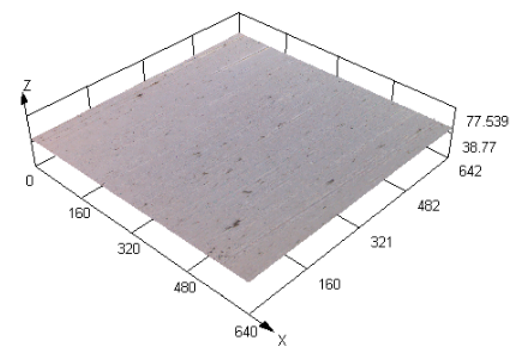
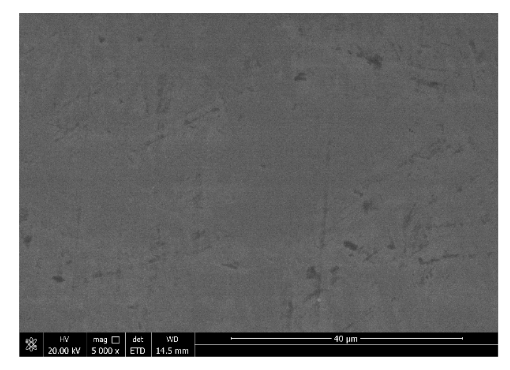
The composition of the plating solution is provided in Table 1. A NiSO4 solution served as the main source of Ni2+ in the solution; a NiCl2 solution was used as an anodic activator to prevent anodic passivation; a H3PO3 solution provided P atoms for the coating; a H3BO3 solution was used as the buffer reagent to adjust the pH value in the bath; C6H8O7 (citric acid) was used as a complexing agent to prevent precipitation in the electrochemical reaction, increase the deposition rate and stability, and improve the coating quality; and CH4N2S (thiocarbamide) was used as a whitener to refine the grain size. C12H25SO4Na (sodium dodecyl sulfonate) was used as a surfactant. A 45 steel workpiece (25 mm × 10 mm × 8 mm) was used as the base material. The main component of 45 steel is Fe, and the compositions of the remaining elements are shown in Table 2. It was polished with sandpaper with 320, 800 and 1500 grits. The 3D morphology of the 45 steel after polishing pretreatment is shown in Figure 2. The surface morphology of the 45 steel surface is shown in Figure 3. The surface square root roughness of 45 steel substrate with polishing pretreatment was 0.006, and the root mean square roughness was 0.008. The activation steps are as follows: oil removal → ultrasonic cleaning → weak activation → ultrasonic cleaning → strong activation → ultrasonic cleaning → blow dry → seal. The function of drying and sealing the workpiece is to prevent oxidation.
The depth of the workpiece immersed in the plating solution was 20 mm. The current densities during deposition were 20, 30, 40, 50 and 60 A·cm−2. According to the preliminary tests, the flow velocity was 4.5 m·s−1, and a temperature of 65 °C had the better effect on the processing area and had good surface quality and wear resistance. According to the previous test, the flow rate was set at 4.5 m·s−1, and the bath temperature was set at 65 °C.

2.3. Testing Equipment

A scanning electron microscope (FEI–SEM, Quanta FEG250; FEI Instruments, Hillsboro, OR, USA) was used in observing and analysing the surface morphology of the coating and the surface morphology of the coating wear scar. The image type of the secondary electron image was selected for observation. The acceleration voltage was set at 3–15 kV, the scanning speed was 20 μs and 100–30,000× magnification was used.
An energy dispersive spectrometer (EDS; XFlash 5030 BrukerAXS, Inc., Berlin, Germany) was used in determining the chemical composition of the coating. The energy spectrometer is often used in conjunction with scanning electron microscopy, which is used in quantitatively and qualitatively analysing related elements in the related regions of a microscopic surface topography in a short time. It is an important supporting instrument.
Microstructure, grain size and phase composition were analyzed with an X-ray diffraction system (XRD; PANalytical X’pert; PANalytical Inc., Malvern, UK). The equipment parameters were as follows: working voltage, 40 kV, the scanning range (2θ), 20°–90° and scanning rate, 5°·min−1.
A micro-hardness tester (Duramin-40; Strous, Ballerup, Denmark) was used to measure the micro-hardness of the coating. The measurement method of microhardness was held for 15 s under a load of 100 g, and the average of five measurements was obtained.
A CFT-I type material surface performance comprehensive tester was used in the friction and wear test. A grinding ball with a diameter of 5 mm was used for reciprocating grinding on the surface of the coating for 20 min. The reciprocating speed was set at 500 T·min−1, the wear scar length was 4 mm and the load was 320 g. The selected parameters used in characterising the wear marks on the coating surface were width, depth and cross-sectional area.
We measured wear morphology with an OLYMPUS LEXT OLS4100 laser confocal microscope. Images were collected through laser scanning in a non-contact way and used in observing the three-dimensional morphology and measuring the roughness of the sample surface. The maximum magnification was 17 m 280×, and the maximum resolution was 10 nm.

3. Result and Discussion

3.1. Analysis of the Surface Morphology of the Coating

The surface micro-morphology of the Ni–P alloy coatings prepared through immersion-assisted jet-electrodeposition and jet- electrodeposition at different current densities is shown in Figure 4. Here, 30 A·dm−2 (J) represents traditional jet-electrodeposition at a current density of 30 A·dm−2; 30 A·dm−2 represents immersion-assisted jet-electrodeposition at a current density of 30 A·dm−2. The surface of the coatings had a typical cell structure, and the flatness and density of the coatings changed to a certain extent after the process and current density were changed. The Ni–P alloy coating prepared by jet-electrodeposition is shown in Figure 4a. The surface had a clear cell structure with clear boundaries, and agglomeration between the cells led to the formation of nodules (region A), but many pits and protrusions appeared on the surface, and the surface density was low. Figure 4b−f show Ni–P alloy coatings prepared through immersion-assisted jet-electrodeposition. The surface morphology of the coatings improved to a certain extent (regions B, C, D, E and F). With increasing current density, the surface quality of the coating surface tended to increase first and then decrease. Figure 4d shows that the cell structures on the surface of the coating electrodeposited at 40 A·dm−2 were refined, the boundaries became blurred, and the number of pits and protrusions decreased (region D). The main reason was that immersion-assisted jet-electrodeposition improves the limiting current density, greatly accelerating the deposition rate of Ni2+ [17]. In addition, the workpiece area immersed in the plating solution increased the deposition area per unit time, which provided additional cellular structures nucleation attachment points. It alleviated the unstable state of the deposition process of Ni2 + on the cathode surface as the nozzle reciprocated. When the current density increased from 40 to 50 A·dm−2 (Figure 4e), no obvious cell structure appeared on the surface of the coating. When the current density was 50 A·dm−2, the coating surface was very flat, and the density increased (region E). Cathode overpotential increased with current density. Although such increase is known to promote the nucleation of a cathode workpiece surface [17,18], when the current density continued to increase to 60 A·dm−2, the surface quality of the coating deteriorated (Figure 4f; region F). When the current density continued to increase, it caused concentration polarization near the cathode workpiece [17,18,19]. The rapid deposition of Ni2+ ions reduced the ion concentration around the cathode and coarsened the grains.
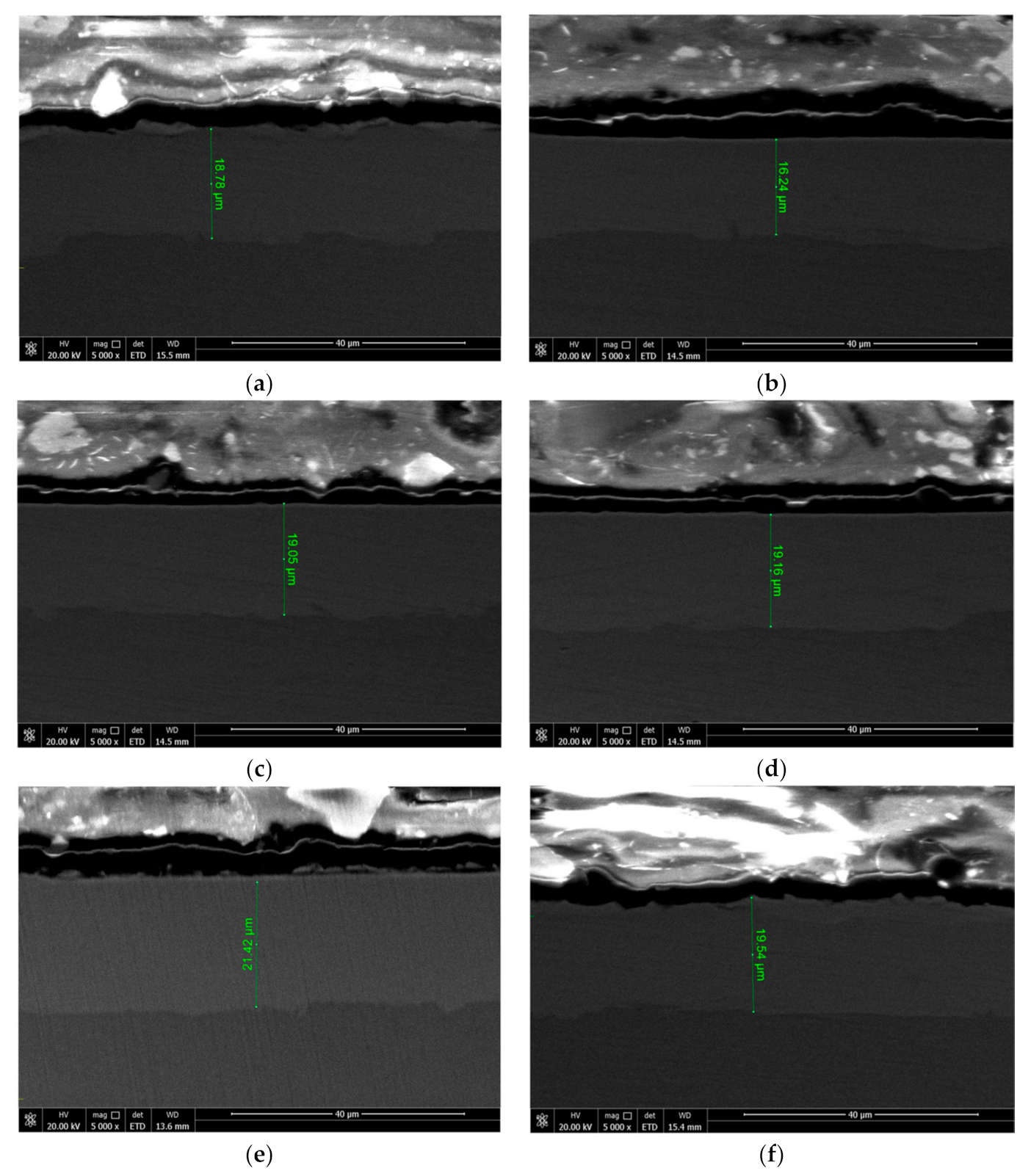
The section micro-morphology of Ni–P alloy coatings prepared by immersion-assisted jet-electrodeposition and jet-electrodeposition at different current densities are shown in Figure 5. Figure 5a shows the section micro-morphology of a Ni–P alloy coating prepared by traditional jet-electrodeposition with a thickness of 18.78 μm. The section micro-morphology of the Ni–P alloy coating prepared by immersion-assisted jet-electrodeposition is shown in Figure 5b−f. It could be seen that with increasing current density, the thickness of the coating tended to increase first and then decrease. When the current density was 30 A·dm−2, the thickness of the Ni–P coating was 19.05 μm, which indicates that, compared with traditional jet-electrodeposition, immersion jet-electrodeposition increased the surface growth area of the coating, increased the nucleation point of the cell, and accelerated the deposition rate. When the current density was 50 A·dm−2, the thickness of the Ni–P coating reached the maximum, which was 21.42 μm, indicating that the immersion jet-electrodeposition increased the limiting current density of the coating. At this time, the current density of the deposited coating was the best and the deposition growth rate was the fastest.

3.2. Analysis of Elemental Composition and Microstructure of the Coating

The Ni−P alloy coatings prepared through immersion-assisted jet-electrodeposition and spray electrodeposition were tested by EDS. The analysis results of the element content are shown in Table 3, where 30 (J) represents the Ni−P alloy coating prepared through traditional jet-electrodeposition at a current density of 30 A·dm−2. The Ni content in the Ni−P coating prepared through immersion-assisted jet-electrodeposition was higher than that of the Ni−P coating prepared through jet-electrodeposition. At the same or lower current density, the immersion-assisted jet-electrodeposition of the workpiece immersed in the plating solution reduced the unevenness of the plating layer because of the uneven jet of the plating solution, and thus Ni2+ deposition was more stable. The workpiece immersed in the plating solution absorbed the temperature of the plating solution, and the process eliminated the influence of the temperature gradient generated in the impingement jet and free jet areas because of the difference between the temperatures of the workpiece surface and plating solution during jet-electrodeposition. It accelerated the free movement and deposition rate of Ni2+ [16]. Moreover, when the current density was increased from 20 to 50 A·dm−2, the Ni content increased with current density. The increase in current density accelerated the Ni2+ deposition rate, resulting in an increase in the Ni content in the coating. When the current density was 60 A·dm−2, the Ni content in the coating decreased. As the current density increased, the increase in cathode polarization accelerated the depletion of Ni2+ in the diffusion layer near the cathode, resulting in a decrease in the concentration of Ni2+ in the plating solution near the cathode. This decrease is a characteristic of the concentration polarization phenomenon, which reduced the Ni content in the coating. However, under different current densities, the P content in the coating tended to be stable mainly because Ni−P deposition is an indirect induced co-deposition [20].
Figure 6 is the XRD diffraction pattern of the Ni−P alloy coating under different parameters and different manufacturing processes. A high-intensity diffraction peak appeared in the patterns of all the coatings near a 2-theta angle of 45°, which represented the (111) plane of a face-centered cubic Ni. The (111) plane was the dominant plane, which may be related to the lower surface energy of this plane during deposition [21]. The XRD diffraction peak of P in the line graph is not obvious. The EDS analysis results showed that the content of P in the coating was much lower than that of Ni, and thus the diffraction peak of P was extremely weak. Moreover, Ni and P ions formed a supersaturated solid solution of Ni during deposition [22], and finally caused the diffraction peaks of Ni and P to coincide. Table 4 shows the grain sizes of Ni (111) in the Ni−P coatings prepared at different current densities, where 30 (J) represents Ni−P coatings prepared by jet-electrodeposition. When the current density was 50 A·dm−2, the grain size of Ni (111) element in the Ni−P coating prepared through immersion-assisted jet-electrodeposition was the smallest (6.6 nm). When the current density was 20 or 60 A·dm−2, the grain size increased to 8.8 or 7.2 nm, respectively. Owing to an increase in current density, the deposition rate of the ions and the nucleation rate increased, and thus the grains were refined. However, when the current density continued to increase, the grains became coarse with the occurrence of concentration polarization. As shown in Table 4, the grain size of Ni (111) element in the Ni−P coating prepared through traditional jet-electrodeposition was smaller than that of the coating prepared through immersion-assisted jet-electrodeposition. The reasons may be that the impact energy of the plating solution on the coating was strong and the coating was mechanically activated during tradition jet-electrodeposition; these effects may have resulted in fine plating particles [13].

3.3. Analysis of Microhardness of Coating

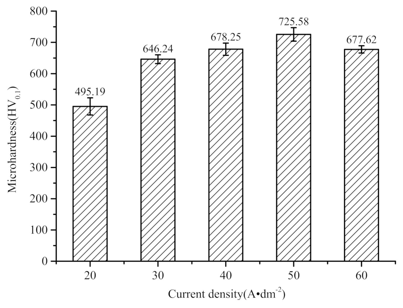
The microhardness of the coating prepared through jet-electrodeposition was 612.31 ± 15.71 HV0.1. Figure 7 reflects the microhardness of the coatings prepared through immersion-assisted jet-electrodeposition at different current densities. To test the microhardness, we measured five values on the surface of the coating, obtained the average value as the measurement result, and calculated the error range as the uncertainty. The microhardness of the coatings prepared through immersion-assisted jet-electrodeposition improved compared with that of the coatings prepared through jet-electrodeposition. The average microhardness of the Ni−P alloy coating prepared through immersion-assisted jet-electrodeposition reached a maximum value of 725.58 ± 21.56 HV0.1 at a current density of 50 A·dm−2. Microhardness increased by 18.50% compared with that of the coating prepared through jet-electrodeposition. The reason was that the immersion of the workpiece in the plating solution greatly accelerated the deposition rate, resulting in the higher density of the coating. However, when the current density increased to 60 A·dm−2, the microhardness of the coating decreased, and surface quality deteriorated. The reason was that when the current density continued to increase, the cathodic hydrogen evolution reaction intensified, increasing the concentration difference polarization of the plating solution during deposition, the grain size, and the degree of hydrogen permeation of the coating; these effects led to the appearance of surface defects and reduced the hardness of the coatings [10]. In addition, the edge effect became obvious with increasing current density and reduced the surface quality and the microhardness of the coating.

3.4. Analysis of the Wear Resistance of the Coating

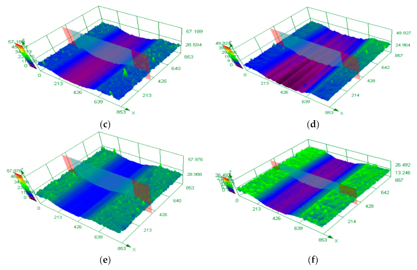
Under the conditions of room temperature (25 °C) and no lubrication, a CFT-I material surface performance comprehensive tester was used in conducting friction and wear tests on the coating. The three-dimensional morphology and parameters of the wear scars of the coatings prepared under different current densities detected by the confocal microscope are shown in Figure 8 and Table 5, respectively. In this test, the wear resistance of the coating was determined from the width, depth, cross-sectional area, and friction mechanism of the wear scar. Figure 8 and Table 5 show that the width, depth, and cross-sectional area of the Ni–P coating prepared through immersion-assisted jet-electrodeposition were smaller than those of the coating prepared through jet-electrodeposition. After immersion-assisted jet-electrodeposition, the wear scar parameters of the coating first decreased and then increased with increasing current density. Under the same wear scar length, the amount of wear on the coating decreased with depth, cross-sectional area size, and wear scar width, indicating enhanced wear resistance [23]. The best wear resistance and the smallest width, depth, and cross-sectional area of the wear scar were observed at a current density of 50 A·dm−2. Under this current density, the coating grains were uniform, the surface was flat, the density was high, and the ability to resist plastic deformation was strong, consistent with the microhardness analysis above. As the current density increased to 60 A·dm−2, the width, depth, and cross-sectional area of the coating’s wear scar increased. The main reason is that when the current density is large, the uneven grain growth of the plating layer causes the density to decrease, and the ability to resist plastic deformation decreases.
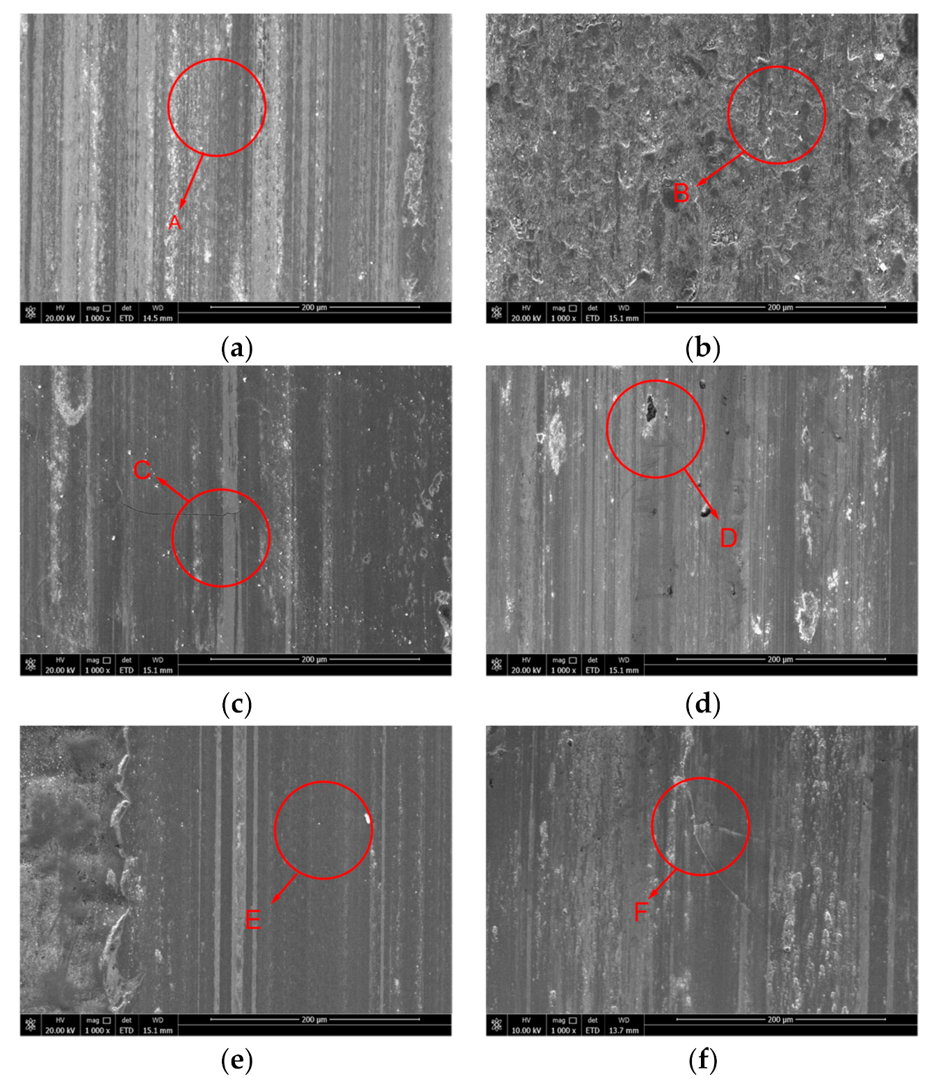
After the friction and wear test, the morphology of the coating wear scar was analyzed through SEM. The morphology is shown in Figure 9. As shown in Figure 9a, a large number of furrows appeared on the wear surface of the Ni−P coating prepared through spray electrodeposition, and many pits and protrusions appeared because the coating fell off (region A). The friction mechanism was adhesive wear and surface fatigue wear. The main reason was that the heat generated by friction softened the Ni−P alloy coating. In addition, plastic deformation occurred at the contact point. As the grinding ball slid back and forth on the coating surface, the adhesion point was cut off under the action of shear stress, which resulted in the migration of materials on the surface to form furrows. After the ‘sinusoid-like signal’ change of the shear stress on the coating surface had occurred, the coating surface hardened because of fatigue wear and falling off. The furrows, bumps, and pits on the wear scar surface of the Ni−P coating prepared through immersion-assisted jet-electrodeposition were significantly reduced, and the friction mechanism was mainly abrasive wear. The main reason was that in immersion-assisted jet-electrodeposition, the ion deposition rate is faster, and the electric field is more stable. Thus, the Ni−P coating prepared was denser and had a higher degree of microhardness [10]. According to Archard’s law [24], under the same test conditions, the wear resistance of a coating is proportional to its microhardness. In Figure 9b−d, slight cracks appeared on the surface of the wear scar, but the surface quality of the wear scar greatly improved (regions B, C and D), suggesting that the bonding of the coating to the substrate was not particularly tight and cracks were generated during the wear process because the current density was slightly smaller [7]. When the current density increased to 50 A·dm−2, as shown in Figure 9e, no obvious furrow or shedding phenomenon occurred on the surface of the coating wear scar, and no cracks appeared (region E). The friction mechanism was mainly based on abrasive wear. However, as the current density continued to increase to 60 A·dm−2, obvious cracks appeared on the surface of the wear scar of the coating, as shown in Figure 9f (region F). Current density increased during the deposition process, and thus the P content and the amount of supersaturated solid solution of Ni in the coating increased [22]. A strong internal stress was generated, and a crack was generated during the wear process.

4. Conclusions

  • In immersion-assisted jet-electrodeposition, the workpiece is in a stable plating bath environment, the temperature is stable, and the cathode can be effectively replenished. Moreover, the limiting current density is improved, and thus the Ni−P alloy coating prepared through this process is better than that prepared through jet-electrodeposition. The surface of the coating is smoother, defects such as pits and protrusions are reduced, and hardness and wear resistance are improved;
  • The surface of the Ni−P alloy coating prepared by immersion-assisted jet-electrodeposition exhibits a typical cell structure. With increasing current density, the overpotential of cathode increases and the nucleation rate of surface cells of the subsequently increases. In addition, the surface quality and thickness of the Ni−P alloy coating increases first and then decreases. When the current density is 50 A·dm−2, the cell structure of the coating is uniform, the thickness of the Ni−P coating reaches the maximum, which is 21.42 μm, the boundary is blurred, and the smallest grain size is observed, i.e., the surface quality is the best;
  • The grain size of the Ni−P alloy coating prepared through immersion-assisted jet-electrodeposition decreases first and then increases as current density increases. The reason is that the nucleation rate increases with current density, and this increase contributes to grain refinement. When the current density is 50 A·dm−2, the grain size reaches a minimum value of 6.6 nm, and the Ni element content reaches a maximum of 98.25%. When the current density continues to increase to 60 A·dm−2, the P content reaches a maximum of 3.45%;
  • The microhardness of Ni−P alloy coatings prepared through immersion-assisted jet-electrodeposition presents a trend of increasing first and then decreasing as current density increases. The reasons are the increase in deposition rate and a dense coating surface without defects after the increase in current density. When the current density reaches the highest average microhardness (725.58 HV0.1), it is approximately 46.5% higher than that when the current density is 20 A·dm−2, and the effect is remarkable. The increase in hardness is beneficial to the improvement of wear resistance;
  • With increasing current density, the improvement of microhardness of the coating can significantly improves the wear resistance of the coating, and the two are directly proportional. The Ni−P alloy coating prepared by immersion-assisted jet-electrodeposition has the best wear resistance when the current density is 50 A·dm−2, and the width, depth, and cross-sectional area of the wear scar of the coating are the smallest, which are 425.494 μm, 7.782 μm and 2266.533 μm2, respectively. No obvious furrow and shedding phenomenon or cracks are observed on the surface of the coating wear scar. The friction mechanism is mainly based on abrasive wear.

Author Contributions

Conceptualization, Z.S. and J.X.; methodology, J.X., Z.Z., and Z.S.; software, Z.S. and M.J. (Minjie Jiang); validation, Z.Z. and M.J. (Minjie Jiang); formal analysis, J.X. and Z.S.; investigation, H.W. and M.J. (Meifu Jin); resources, J.X.; data curation, Z.S. and H.W.; writing—original draft preparation, J.X. and Z.S.; writing—review and editing, M.J. (Meifu Jin) and H.W.; visualization, Z.S. and Z.Z.; supervision, J.X., M.J. (Minjie Jiang), and Z.Z.; project administration, H.W. and J.X.; funding acquisition, J.X. and M.J. (Meifu Jin). All authors have read and agreed to the published version of the manuscript.

Funding

Financial support for this work was provided by Jiangsu Agricultural Science and Technology Innovation Fund (Grant number CX (20) 3085); Fundamental Research Funds for the Central Universities (Grant number KYXJ202002).

Institutional Review Board Statement

Not applicable.

Informed Consent Statement

Not applicable.

Data Availability Statement

Not applicable.

Conflicts of Interest

The authors declare no conflict of interest.

References

  1. Li, W.S.; Cui, S.; He, L.; Li, Q.K. Electrochemically deposited Ni-based MoS2 composite coating and its wide temperature range friction properties. China Surf. Eng. 2017, 30, 97–103. [Google Scholar]
  2. Ahmadkhaniha, D.; Zanella, C. The Effects of Additives, Particles Load and Current Density on Codeposition of SiC Particles in NiP Nanocomposite Coatings. Coatings 2019, 9, 554. [Google Scholar] [CrossRef] [Green Version]
  3. Benea, L.; Celis, J.P. Effect of Nano-TiC Dispersed Particles and Electro-Codeposition Parameters on Morphology and Structure of Hybrid Ni/TiC Nanocomposite Layers. Materials 2016, 9, 269. [Google Scholar] [CrossRef] [PubMed] [Green Version]
  4. Rosolymou, E.; Spanou, S.; Zanella, C.; Tsoukleris, D.S.; Köhler, S.; Leisner, P.; Pavlatou, E.A. Electrodeposition of Photocatalytic Sn-Ni Matrix Composite Coatings Embedded with Doped TiO2 Particles. Coatings 2020, 10, 775. [Google Scholar] [CrossRef]
  5. Jiang, W.; Shen, L.; Qiu, M.; Wang, X.; Fan, M.; Tian, Z. Preparation of Ni-SiC composite coatings by magnetic field-enhanced jet electrodeposition. J. Alloys Compd. 2018, 762, 115–124. [Google Scholar] [CrossRef]
  6. Xue, Y.J.; Si, D.H.; Liu, H.B. The influence of electrodeposition methods on the friction and wear properties of Ni-CeO2 nanocomposite coatings. Chin. J. Nonferrous Met. 2011, 21, 2157–2162. [Google Scholar]
  7. Hessam, R.; Najafisayar, P. The effects of applied current density and bath concentration on the morphology, crystal structure and optical properties of electrodeposited hematite thin films. Thin Solid Films 2019, 692, 137633. [Google Scholar] [CrossRef]
  8. Shourije, S.J.; Bahrololoom, M.E. Effect of current density, MoS2 content and bath agitation on tribological properties of electrodeposited nanostructured Ni-MoS2 composite coatings. Tribol. Mater. Surf. Interfaces 2019, 13, 76–87. [Google Scholar] [CrossRef]
  9. Fan, H.; Zhao, Y.P.; Jiang, J.; Wang, S.; Shan, W.; Ma, R. Pulse jet electrodeposition of nanocrystal line copper and its application as an electrical discharge machining electrode. Int. J. Electrochem. Sci. 2020, 15, 2648–2658. [Google Scholar] [CrossRef]
  10. Song, Z.Y.; Zhang, H.W.; Fu, X.Q. Effect of Current Density on the Performance of Ni-P-ZrO2-CeO2 Composite Coatings Prepared by Jet-Electrodeposition. Coatings 2020, 10, 616. [Google Scholar] [CrossRef]
  11. Qiao, G.Y.; Jing, T.F.; Wang, N.; Gao, Y.; Zhao, X.; Zhou, J.; Wang, W. High-speed jet electrodeposition and microstructure of nanocrystalline Ni–Co alloys. Electrochim. Acta 2005, 51, 85–92. [Google Scholar] [CrossRef]
  12. Rajput, M.S.; Pandey, P.M.; Jha, S. Modelling of high speed selective jet electrodeposition process. J. Manuf. Process. 2015, 17, 98–107. [Google Scholar] [CrossRef]
  13. Tian, J.; Song, H.; Zheng, X.H.; Zhang, Q.; Wang, M. High performance Co–Cr3C2 composite coating by jet electrodeposition. Surf. Eng. 2017, 34, 861–869. [Google Scholar]
  14. Ning, D.D.; Zhang, A. Enhanced Wear Performance of Cu-Carbon Nanotubes Composite Coatings Prepared by Jet Electrodeposition. Materials 2019, 12, 392. [Google Scholar] [CrossRef] [Green Version]
  15. Fu, X.Q.; Shen, Z.Y.; Chen, X.X. Influence of Element Penetration Region on Adhesion and Corrosion Performance of Ni-Base Coatings. Coatings 2020, 10, 895. [Google Scholar] [CrossRef]
  16. Singh, C.; Tiwari, S.K.; Singh, R. Exploring environment friendly nickel electrodeposition on AZ91 magnesium alloy: Effect of prior surface treatments and temperature of the bath on corrosion behaviour. Corros. Sci. 2019, 151, 1–19. [Google Scholar] [CrossRef]
  17. Li, T.T.; Ling, L.; Lin, M.C.; Jiang, Q.; Lin, Q.; Lou, C.W.; Lin, J.H. Effects of ultrasonic treatment and current density on the properties of hydroxyapatite coating via electrodeposition and its in vitro biomineralization behavior. Mater. Sci. Eng. C Mater. Biol. Appl. 2019, 105, 110062. [Google Scholar] [CrossRef]
  18. Li, N.B.; Xu, W.H.; Zhao, J.H.; Xiao, G.Y.; Lu, Y.P. The significant influence of ionic concentrations and immersion temperatures on deposition behaviors of hydroxyapatite on alkali- and heat-treated titanium in simulated body fluid. Thin Solid Films 2018, 646, 163–172. [Google Scholar] [CrossRef]
  19. Li, Y.D.; Jiang, H.; Huang, W.H.; Tian, H. Effects of peak current density on the mechanical properties of nanocrystalline Ni–Co alloys produced by pulse electrodeposition. Appl. Surf. Sci. 2008, 254, 6865–6869. [Google Scholar] [CrossRef]
  20. Lelevic, A.; Walsh, F.C. Electrodeposition of Ni P composite coatings: A review. Surf. Coat. 2019, 378, 124803. [Google Scholar] [CrossRef] [Green Version]
  21. He, Y.; Wang, S.C.; Walsh, F.C.; Chiu, Y.L.; Reed, P.A.S. Self-lubricating Ni-P-MoS2 composite coatings. Surf. Coat. Technol. 2016, 307, 926–934. [Google Scholar] [CrossRef] [Green Version]
  22. Shui, Y. The research status and development trend of Ni-P coating. Surf. Technol. 2002, 1, 1–4. [Google Scholar]
  23. Li, L.; Lu, Z.X.; Pu, J.B.; Wang, H.; Li, Q.; Chen, S.; Zhang, Z.; Wang, L. The superlattice structure and self-adaptive performance of C–Ti/MoS2 composite coatings. Ceram. Int. 2020, 46, 5733–5744. [Google Scholar] [CrossRef]
  24. Anas, N.S.; Krishna, L.R.; Dash, R.K.; Vijay, R. Tribological Performance of Al Alloys Dispersed with Carbon Nanotubes or Ni-Coated Carbon Nanotubes Produced by Mechanical Milling and Extrusion. J. Mater. Eng. Perform. 2020, 29, 1630–1639. [Google Scholar] [CrossRef]
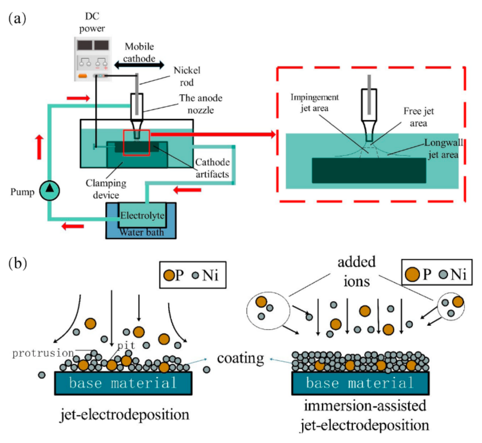
Figure 1. Schematic diagram of electrodeposition process. (a) Experimental device; (b) electrodeposition principle.
Coatings 11 00527 g001
Figure 2. Three-dimensional morphology of the 45 steel.
Coatings 11 00527 g002
Figure 3. Surface morphology of the 45 steel.
Coatings 11 00527 g003
Figure 4. Surface micro-morphology of the coating. (a) 30 A·dm−2(J) (b) 20 A·dm−2 (c) 30 A·dm−2 (d) 40 A·dm−2 (e) 50 A·dm−2 (f) 60 A·dm−2.
Coatings 11 00527 g004
Figure 5. Section micro-morphology of the coating. (a) 30 A·dm−2 (b) 20 A·dm−2 (c) 30 A·dm−2 (d) 40 A·dm−2 (e) 50 A·dm−2 (f) 60 A·dm−2.
Coatings 11 00527 g005
Figure 6. XRD pattern of Ni–P alloy coatings.
Coatings 11 00527 g006
Figure 7. Microhardness of Ni–P alloy coatings prepared by immersion-assisted jet-electrodeposition at different current densities.
Coatings 11 00527 g007
Figure 8. Three-dimensional morphology of wear marks. (a) 30 A·dm−2 (J), (b) 20 A·dm−2 (c) 30 A·dm−2 (d) 40 A·dm−2 (e) 50 A·dm−2 (f) 60 A·dm−2.
Coatings 11 00527 g008aCoatings 11 00527 g008b
Figure 9. Surface morphology of wear marks. (a) 30 A·dm−2(J) (b) 20 A·dm−2 (c) 30 A·dm−2 (d) 40 A·dm−2 (e) 50 A·dm−2 (f) 60 A·dm−2.
Coatings 11 00527 g009
Table 1. Composition of the plating solution.
CompositionContent/(g·L−1)
NiSO4·6H2O200
NiCl2·6H2O30
H3PO320
H3BO330
C6H8O760
CH4N2S0.01
C12H25SO4Na0.08
Table 2. Chemical element composition of 45 steel (wt.%).
ElementCSiMnCrNiCu
Content0.42−0.500.17–0.370.50–0.80≤0.25≤0.30≤0.25
Table 3. The quality fraction of the surface elements of the coating.
Current Density/(A·dm−2)Ni/(wt.%)P/(wt.%)
30 (J)70.781.94
2079.260.77
3084.321.98
4089.841.38
5098.251.73
6082.283.45
Table 4. Grain size of Ni(111) element in Ni–P coatings.
Current Density/(A·dm−2)2θ/(o)D/(nm)
30 (J)44.7596.6
2044.8368.8
3044.9737.0
4044.8076.7
5044.9006.6
6044.7947.2
Table 5. Coating wear mark parameters.
Current Density/(A·dm−2)Width/
(μm)
Height/
(μm)
Scratch/
Area (μm2)
30 (J)603.140 ± 15.37213.620 ± 1.2325039.194 ± 105.577
20592.257 ± 18.26611.623 ± 1.8393922.100 ± 152.228
30516.905 ± 18.95211.191 ± 1.3253623.217 ± 131.174
40510.434 ± 14.27510.607 ± 0.9233204.018 ± 138.380
50425.494 ± 10.3387.782 ± 0.5742266.533 ± 101.909
60465.117 ± 16.1598.441 ± 1.3912593.077 ± 146.263
Publisher’s Note: MDPI stays neutral with regard to jurisdictional claims in published maps and institutional affiliations.