Article

Effect of Riveting Angle and Direction on Fatigue Performance of Riveted Lap Joints

1
School of Mechanical Engineering, Northwestern Polytechnical University, Xi’an 710072, China
2
AVIC Xi’an Aircraft Industry Group Company LTD, Xi’an 710089, China
3
Key Laboratory of Advanced Manufacturing Technology of Zhejiang Province, College of Mechanical Engineering, Zhejiang University, Hangzhou 310027, China
*
Author to whom correspondence should be addressed.
Coatings 2021, 11(2), 236; https://doi.org/10.3390/coatings11020236
Submission received: 24 January 2021 / Revised: 7 February 2021 / Accepted: 9 February 2021 / Published: 16 February 2021

Abstract

:
Riveting is the most commonly used connection method in aircraft assembly, and its quality has a crucial effect on the fatigue performance of aircraft. Many factors affect the riveting quality, among which the influence of the riveting angle and direction is not clear. In this paper, a three-dimensional finite element model of single-rivet lap joints is established and verified by the driven head geometry and the riveting force data obtained from the riveting experiments. Then, by adjusting the angle and direction of the punch in the finite element model, the riveting process is simulated at the angles of 0°, 1°, 2°, and 3° and the directions of 0° and 180° to investigate the deformation of the lap joints, the stress distribution around the hole, and the stress distribution of the rivet. Finally, the fatigue tests of the single-rivet lap joints are performed and the influence of the riveting angle and direction on the connection quality and fatigue performance of the riveting joints is analyzed.

1. Introduction

Airplanes have become an indispensable means of transportation in modern society. However, the survival rate of aviation accidents caused by airplane failures is extremely low, and airplane safety has always been a key issue of people’s attention. Among the various failures of aircraft, most of them occur at the joints of the aircraft components. According to statistics, 60–90% of the damage of mechanical parts belongs to fatigue damage [1], and fatigue fractures mostly occur at the connection joints. Mechanical connections include threaded connection, rivet connection, keyway connection, and wedge connection, while riveting is a widely used connection technique in aircraft assembly due to its reliable quality, light weight, and low cost. Therefore, the riveting quality in aircraft assembly is very important and should be guaranteed.
In the traditional design of aircraft, only static strength is generally considered. However, as the service life of aircraft continues to extend, the problem of body fatigue damage gradually appears. Nowadays, aircraft have a life span of about 40,000 to 60,000 flight hours, and fatigue damage has become the main form of structural damage. Therefore, the fatigue failure of the connecting parts of aircraft structural parts has become the focus of attention of researchers from all over the world. Li et al. [2,3] used a combination of finite element analysis and experiments to study the residual stress and strain of single-rivet and three-rivet countersunk head riveting parts and analyzed the influence of the maximum principal stress distribution and the residual stress on a riveted joint during the tensile load stage; Bedair et al. [4] studied the circumferential stress, axial stress, and radial stress distribution close to the connecting hole of a multi-nail riveted part through the finite element method and found that the maximum tensile and compressive stress on the parts is greatly affected by the secondary bending; Skorupa et al. [5] studied the influence of factors such as the type and material of rivets, the material and thickness of connecting parts, the pressure riveting force, and secondary bending on the fatigue performance of a riveted joint through experimental methods. They found that the secondary bending has the most prominent effect on the fatigue performance of the riveted joint. Sathiya et al. [6] studied the influence of the uneven distribution of the rivet load on the fatigue life, failure, and damage tolerance design of riveted parts; Wei et al. [7] studied a method called MDFR that can evaluate multiple riveted structures quickly and analyze different design solutions more effectively.
Different riveting process parameters have a great influence on the residual stress distribution of riveting and the fatigue life of the connecting structure. Liao et al. [8] proposed a fatigue life prediction method: the local stress distribution around the connecting hole is obtained by the finite element method. The fatigue life of the structure is calculated based on the local stress–strain method. Manes et al. [9,10,11,12,13,14] analyzed and optimized the assembly and riveting process parameters of single-rivet joints and multi-rivet joints, which effectively reduced the structural deformation caused by the riveting process and improved the design accuracy. The subsequent riveting process parameters can improve the fatigue life of the riveted structure and effectively suppress riveting deformation. Nowell et al. [15] and Yuan et al. [16] used an optical microscope to analyze the influence of structural parameters on the fatigue life and fracture behavior of riveted structures with the aid of nail load transfer tests and fatigue tests. Combined with finite element software to assist in the analysis, they found that they can effectively improve the fatigue resistance of the joint structure with the best structural parameters for performance.
The connection quality of riveting parts is affected by many factors, such as hole-making accuracy, pressure riveting method, pressure riveting sequence, interference level, pre-tightening force, and rivet distribution form. However, whether through finite element simulation or pressure riveting experiments, most of the research is under the ideal pressure riveting angle, that is, the angle between the axis of the rivet rod and the axis of the punch is 0°. In other words, the influence of different riveting angles and directions on the connection quality is still unclear. Aviation standards stipulate that the angle between the axis of the rivet rod and the axis of the punch should not exceed 2° during riveting [17]. However, in the actual aircraft riveting process, the ideal pressure riveting angle (0°) is rarely achieved due to the limited riveting position, the worker’s riveting stability, etc. Therefore, it is of great significance to study the fatigue performance of joints under different riveting angles and directions to achieve long-life assembly of aircraft.
The paper takes the riveting angle and direction as the controlling factors, focuses on the influence of the pressing angle and direction of the punch on the stress distribution, load transfer, fatigue life, and strain of the dangerous area of the riveted lap joints, and summarizes the rules to improve the fatigue life of lap joints. The ABAQUS6.14-4 software is used to establish a three-dimensional finite element model of the single-riveted lap joints, and then the pressure riveting process is dynamically simulated. After the simulation is completed, the simulation data are used to analyze the riveting deformation and stress distribution. An automatic riveting machine is used to perform pressure riveting tests. The driven head size and pressure riveting force data obtained from the test are compared with the finite element data to verify the correctness of the finite element model. Then, the riveting process is simulated at angles of 1°, 2°, and 3° and directions of 0° and 180° by adjusting the angle and direction of the punch in the finite element model, and on this basis, a static stretching analysis step is added. By analyzing the deformation of the riveted joints, the stress distribution around the hole, and the stress distribution of the rivet, the influence of the riveting angle and direction on the connection quality and fatigue performance of the riveted lap joints is studied. The riveting test of the single-rivet lap joints is designed and the INSTRON-8872 (Instron Corporation, Canton, OH, USA) fatigue testing machine is used to perform the fatigue tests. The fatigue test result is analyzed and explained in combination with the finite element simulation data. The effects of the riveting angle and direction on the fatigue of the riveted lap joints are discussed.

2. Basic Pressure Riveting Model Simulation and Verification

This paper mainly studied the riveting of countersunk head rivets. The finite element simulation and the production of test pieces are based on pressure riveting. As shown in Figure 1, the complete pressure riveting process can be divided into four stages from the beginning of riveting to the formation of the rivet head.
  • Stage 1: This stage starts from the contact between the punch and the rivet. As the displacement of the punch increases, the pressure riveting force gradually increases, the rivet begins to deform, and the shank is upset as a whole. When the nail bar touches the connecting hole, this stage ends. The first stage only involves the deformation of the rivet, as the pressure riveting force has not been transmitted to the riveting part and the riveting joint will naturally not be deformed by force.
  • Stage 2: This stage starts from the contact between the rivet rod and the connecting hole. As the displacement of the punch increases, the contact area between the rivet rod and the inner wall of the connecting hole begins to increase. When the rivet rod is in full contact with the inner wall of the connecting hole, this stage ends. In the second stage, there is both the deformation of the rivet and the deformation of the connecting hole.
  • Stage 3: The displacement of the punch continues to increase, and the tail of the rivet rod begins to be partially upset form the driven head and in contact with the surface of the connecting piece. Due to the friction in the contact area between the driven head and the connecting piece, the material flow changes. At the same time, the pressure transmits from the driven head to the connecting piece and causes the joint to begin to deform. When the punch moves to the specified position, the stage ends. In the third stage, the deformation and force of the riveting parts are the most complicated in the whole process. There is not only the pressure transmitted to the riveted joint through the hole circumference due to the expansion of the rivet in the connecting hole, but also the pressure generated by the driven head contacting the surface of the plate and the friction caused by extension of the driven head.
  • Stage 4: The displacement of the punch begins to decrease and moves away from the riveted joint. During this process, the punch is still in contact with the rivet head, the rivet recovers elastically, and the pressure riveting force begins to gradually decrease. Finally, the punch and the rivet head are separated, and the pressure riveting process ends.

2.1. Finite Element Model of Basic Pressure Riveting

Since riveting is a highly nonlinear problem between multiple objects with complex contact, the ABAQUS/Explicit algorithm was used to simulate the riveting process at a standard angle (0°) and observe the deformation and stress distribution of the riveted joint. Further, because the model is relatively complicated, the three-dimensional model of the lap joint was established by CATIAV5R20 and imported into ABAQUS for pre-processing of the model.
The structure of the riveted lap joint FE model is shown in Figure 2. The connecting piece is composed of two 7050 aluminum alloy plates with a length of 200 mm, a width of 40 mm, and a thickness of 2 mm. The rivet uses a 100° small countersunk head 2A01 rivet, the rivet material is 2117-T4 aluminum alloy, the selected size is 5 mm in diameter and 12 mm in height, and the margin is set as 20 mm. The overall size of the connector is 360 × 40 × 2 mm.
Finite element simulation is still an ideal situation relative to reality. Therefore, the assumptions are about the following situations:
  • During the riveting process, the application of the force load and displacement load are completely continuous without interruption.
  • The rivet and plates in the connector are isotropic homogeneous materials.
  • The initial stress and volume force before riveting are both zero.
  • The temperature during riveting is normal and constant.
The material of the rivet is 2117-T4 aluminum alloy, and the riveting plates are 7050 aluminum alloy. The punch is regarded as an ideal rigid body. The specific material parameters are shown in Table 1 and Table 2. According to the test data, the relationship of the stress (σtrue) and strain (εtrue) of the aluminum alloy in the plastic deformation stage satisfies
σ t r u e = C ( ε t r u e ) m
For serious distortion problems, linear and reduced integral elements with fine meshes should be used. Considering the accuracy of shear strain under contact conditions, C3D8R hexahedral elements are used for the three-dimensional pressure riveting model. The C3D8R element is an 8-node hexahedral linear reduction integration element in Abaqus. When calculating large deformation problems, the C3D8R element is easier to converge, which is convenient to observe the failure trend of the structure. Further, when the grid is deformed, the accuracy of the analysis will not be greatly affected. Due to the huge elastic and plastic deformation of the rivet during the pressure riveting process, the connecting hole that matches the rivet will also undergo obvious elastic–plastic deformation due to the extrusion of the rivet rod. The resulting stress and strain will be very important for the evaluation of the riveting quality and the study of fatigue life later, so the area around the rivet and the connecting hole is set with a denser grid, and other areas are divided into a sparse grid. The model with a divided mesh is shown in Figure 3, and the total number of elements is 81,321.
According to the above pressure riveting process, two analysis steps are set up in the model to simulate the pressing process of the punch (stages 1, 2, and 3 in Figure 1) and the rising process (stage 4). Both analysis steps use dynamic explicit analysis, and the time of each analysis step is set to 0.001 s.
The surface-to-surface contact of the model includes the contact between the punch and the rivet, the contact between the rivet rod and the inner wall of the inner plate hole, the contact between the rivet head, the rod, and the inner wall of the outer plate hole, and the contact between the inner plate and the outer plate. Considering that the contact between the rivet head and the inner plate hole is complicated, it is set as general contact. At the same time, considering that there may be other unknown contacts during the entire riveting process, the surface it contains is selected as “All* with self” when setting the general contact. “All with self” in general contact refers to the mutual contact of the outer surfaces of all parts, including the contact of the outer surfaces of different parts and the self-contact of the outer surface of the same part. It can be applied to the situation where two or more of its own surfaces may come into contact when a large deformation of the component occurs. The contact of multiple surfaces can make the calculation of the riveting deformation process easier to converge.
Considering the accuracy of drilling and countersinking, and the roughness between rivets and plates, a fixed friction coefficient of 0.2 is set for each contact surface [17].
The boundary conditions are shown in Figure 3. In riveting steps, all degrees of freedom for rivet heads are constrained. The X-direction, Y-direction, and Z-direction are constrained on the clamping areas of the upper and lower plates. The clamping area on both sides of the upper and lower boards is fixed in the Y-direction and Z-direction. The degree of freedom in the Z-direction of punches is free so the riveting displacement load can be applied. The displacement (load) of the rigid body reference point corresponding to the punch is set to the pressing amount of the punch, which in this article is 4.2 mm, that is, there is a driven height of about 2.8 mm after the pressure riveting is completed.

2.2. Riveting Deformation and Stress Analysis of Basic Pressure Riveting Model

During the riveting process of the lap joint, both the rivet and the connecting plate undergo a certain degree of elastoplastic deformation. After the punch is removed, these deformations cannot be fully recovered, so there is a certain residual stress. The Mises stress field distribution after riveting is shown in Figure 4. It can be seen that the residual stress mainly exists near the rivet and the hole circumference and gradually decreases along the radial direction from the simulation results. When it is away from the center of the connecting hole by twice the diameter, the residual stress basically becomes zero.
The stress distribution of the rivet and the hole area is shown in Figure 5 and their stress map is consistent. It can be seen from the figure that the residual stress changes not only in the radial direction, but also in the axial direction. The stress concentration is mainly in the contact area between the rivet and the edge of the hole. Compared with the rivet head, the stress concentration on the side of the driven head is greater, up to 595.5 MPa, which exceeds the yield limit of the rivet material. The reason for this result is that the elastoplastic deformation on the side of the driven head is the most severe, and the force is the most complicated. When the rivet is upsetting and deformed, the amount of interference on the side of the driven head and the connecting hole is greater.
After the riveting is completed, the residual circumferential stress on the joint is shown in Figure 6. It can be seen that the residual circumferential stress changes both in the radial direction and in the axial direction. The residual circumferential stress near the hole circumference presents a compressive stress state, which helps to prevent fatigue cracks from nucleating and prolongs the fatigue life of the joint. When away from the hole in the radial direction, the circumferential compressive stress gradually decreases and finally presents a state of tensile stress, and the stress in the tensile stress zone first increases and then decreases. The larger circumferential compressive stress is mainly distributed around the contact area between the driven head and the connecting hole. When the driven head and the rivet head are axially away, the compressive stress gradually decreases. The reason for this result is that the rivet rods at the driven head and nail heads are deformed severely and the amount of interference is large. From the overall observation, it can be seen that the compressive stress area on the driven head side is larger, while the compressive stress area on the rivet head side is smaller. This is due to the larger amount of interference on the driven head side and smaller interference on the rivet head side. Since the compressive stress area of the rivet head side is small, it is easier to become the origin of fatigue cracks than the driven head side.

2.3. Riveting Test Verification of Basic Pressure Riveting Model

On the basis of finite element simulation, the riveting test of the single-riveted lap joint was carried out. The designed and manufactured riveted test piece is shown in Figure 7. The connecting piece is composed of two 7050 aluminum alloy plates and a 100° small countersunk head 2A01 rivet. The dimension and structure are consistent with the finite element model.
The pressure riveting process was completed by the automatic drilling and riveting machine. The automatic drilling and riveting machine was controlled to complete the hole making, countersinking and pressure riveting, and finally the test piece after the riveting was taken off. Figure 8 shows the test process of the automatic drilling and riveting machine for riveting the riveted joints. During the pressure riveting process, the automatic drilling and riveting machine automatically recorded the pressure riveting force data during the process. After the pressure riveting was completed, the driven head diameter data were obtained by measurement.
• Analysis of the driven head size
In the riveting process of aircraft structural parts, the quality inspection of riveting is mainly completed by detecting the size of the driven head after riveting (diameter, height, etc.). Since the driven head is formed through complex elastic–plastic deformation, there are both the interaction between the rivet and the punch and the interaction between the rivet and the plates in this process, and thus the size of the driven head can be used to verify the correctness of the finite element model.
As shown in Table 3, the deviation between the diameter of the driven head obtained by the finite element results and the experiment is within 5%. The experimental results are basically consistent with the finite element simulation results. This shows that the finite element model is correct.
• Analysis of pressure riveting force
In the riveting process of the joint, the pressure riveting force is composed of three parts: the force generated by the elastic–plastic deformation of the rivet, the force generated by the rivet deforming the joint (the squeezing deformation of the hole wall by the rivet rod and the squeezing deformation on the circumference of the hole by the driven head), and the friction force between the rivet and connecting parts. As a result, the pressure riveting force reflects the deformation and stress distribution of the riveting parts (especially around the hole) to a certain extent, and the pressure riveting force can be used to verify the correctness of the finite element model.
It can be seen from the pressure riveting force–displacement data obtained from the experiment and finite element model in Figure 9 that since the finite element model is simplified based on the analysis of the actual riveting condition, the test data are slightly larger than the finite element results, but the trends of the two are similar, and the error is small, which is within an acceptable range. Therefore, the correctness of the finite element model is verified.

3. Influence of Riveting Angle and Direction on Fatigue Performance

When the lap joint is riveted, different riveting angles and riveting directions will affect the deformation of the riveted lap joint, and the residual stress distribution after the pressure riveting will be different, which will affect the fatigue performance of the riveted lap joint. In the study of fatigue performance, researchers are most concerned about fatigue life. Fatigue life refers to the number of cycles or time experienced when a material or part undergoes fatigue failure under alternating stress.
This chapter uses a combination of finite element simulation and fatigue tests to deeply study the influence of the riveting angle and direction on the fatigue performance of the riveted lap joint. Using finite element technology to simulate the riveting and load-bearing process continuously can reflect the effect of residual stress on the fatigue performance of riveted joints, explain the results of the fatigue test, and analyze the pros and cons of the parameters more accurately. The fatigue test can be the most intuitive and true reflection of the influence of the riveting angle and direction on the fatigue performance of the riveted lap joint. Combining simulation with testing and complementing each other’s advantages can help to obtain the influence law of process parameters on the fatigue performance of joints.
During the fatigue test, the riveted lap joint can be loaded with constant amplitude loading, random loading, program loading, and other methods. Among them, constant amplitude loading is a simple and rapid loading method, which is very suitable for the selection of structural component test schemes, comparison of material fatigue characteristics, and determination of process parameters. Relevant tests show that the fatigue failure location during constant amplitude loading is generally the location where fatigue failure occurs during real load loading when the life is in the range of 104–105 [18]. The fatigue test in this paper is mainly to compare the fatigue performance of the riveted lap joint when the riveting parameters are different, and the structure of the joint is relatively simple, so the constant amplitude loading method was used.
When using constant amplitude loading, the alternating stress that changes in the form of a sine curve is generally selected. According to the working and loading conditions of different structural parts, alternating stress loading with different stress ratios is adopted. The structural parts on the aircraft such as the wings and skins are usually subjected to “wave cycle” loads. Therefore, fatigue experiments on their structural parts usually adopt the “wave cycle” loading method with a stress ratio of 0 < R < 1, as shown in Figure 10, take R = 0.2.
According to the basic model of pressure riveting of riveted lap joints in the second section, we adjusted the pressure riveting angle and direction of the punch in the model. The riveting angle is divided into 1°, 2°, and 3°, and the pressure riveting direction is divided into 0° and 180°. Figure 11 is a finite element model with a riveting angle of 3° in the directions of 0° and 180°. Figure 11a is the model when the pressure riveting angle is 3° in the 0° riveting direction; Figure 11b is the model when the pressure riveting angle is 3° in the 180° riveting direction. For the convenience of the following description, the specified symbol x-y is the abbreviation of the model with the pressure riveting angle of y° in the direction of x°, where x takes values of 0 and 180, and y takes values of 0, 1, 2, and 3. For example, 0-3 represents pressure riveting with the punch deflected by 3° under the direction of 0°; 180-3 represents pressure riveting with the punch deflected by 3° under the direction of 180°.

3.1. Riveting Deformation and Stress Analysis of Different Riveting Angles and Directions

By changing the angle and direction of the punch in the basic model, and taking the contrast between the finite element simulation results of 0° and 3° as an example, the influence of the riveting angle and direction on the deformation of the riveted lap joint is explained.
Figure 12 shows the finite element results of the connector with the riveting angle of 3°. When the angle and direction of the punch downward change, the shape of the driven head changes accordingly. At the same time, the contacted part of the driven head and the connecting plate is not a symmetrical distribution along the connecting hole (or rivet rod) axis anymore. The higher side of the punch has a larger contact area and vice versa. The reason can be explained by the theory of plastic flow of metal: Taking the pressing down with a riveting angle of 3° in the direction of 0° (Figure 12b) as an example, when the punch is pressed down, the left side of the punch is high and the right side is low. A wedge-shaped area is formed between the surface of the connecting piece and the opening on the left side is relatively large. When the nail rod undergoes plastic deformation and the metal flows to both sides of the nail hole, the right side will have a large flow resistance due to the narrow space and flow difficultly; the left side has a large space and low flow resistance and flows easily. Therefore, a large amount of metal flows to the left, and the left contact area is larger than the right area. The punch presses down at an angle of 3° in the direction of 0°; c is for the punch to press down at an angle of 3° in the direction of 180°.
When the punch is pressed down to a certain angle, a certain degree of stress concentration occurs at the contact between the rivet head and the connecting hole, and the maximum residual stress of the entire connecting piece also rises. This is because when the punch is pressed down at a certain angle, the rivet rod will tilt to a certain extent, which causes the rivet head to face the connecting hole in the opposite direction, causing a stress concentration. The place where the stress concentration exists is often the initiation source of fatigue cracks, and the fatigue life will be reduced accordingly.
In the fatigue test, the fatigue testing machine performs tensile cyclic loading on the test piece after the riveting is completed. Therefore, it is necessary to apply a tensile force to the riveted lap joint after the pressure riveting is completed to clarify its maximum principal stress distribution and deformation. Figure 13 shows the simulation results of the riveted connection piece after applying the transverse static tension. After being subjected to the transverse static tension, both the plate and the rivet are deformed greatly, and the connecting piece appears with secondary bending. The phenomenon is caused by the fixed transmission path of the load when the two ends of the single-shear structure bear the tensile load.

3.2. Experiment Design and Preparation

For the fatigue performance test of the single-riveted lap joint, the INSTRON 8872 fatigue test system as shown in Figure 14 was used, and the waveform generation, calibration, setting limits, and status monitoring were controlled by a computer. Two sets of fatigue tests were designed for a high-cycle fatigue test and a low-cycle fatigue test. Each group of tests had 5 test pieces (0° standard riveted lap joint, 1° riveted joint under 0° direction (0-1), 1° riveted joint under 180° direction (180-1), 2° riveted joint under 0° direction (0-2), 2° riveted joint under 180° direction (180-2).
According to the number of stress cycles during fatigue failure, fatigue can be divided into high-cycle fatigue and low-cycle fatigue. High-cycle fatigue refers to fatigue with stress cycles higher than 105 during fatigue failure. The stress level on the structural parts that undergo high-cycle fatigue failure is generally lower than the yield limit of the material, and some stress levels are even only about one third of its tensile strength. Low-cycle fatigue refers to fatigue in which the number of stress cycles is less than 104 to 105 during fatigue failure. The stress levels on the structural parts that undergo low-cycle fatigue failure are generally relatively high, usually close to or exceeding the yield limit of their materials.
In this paper, both high-cycle fatigue and low-cycle fatigue are studied. The sine waveform and stress ratio R = 0.2 were selected for fatigue loading. The maximum force in the high-cycle fatigue test was set to 4.2 KN, and the maximum force in the low-cycle fatigue test was set to 5.2 KN; the loading frequency was set to 10 Hz.
Due to the relatively limited sample size of the experiment, the influence law between riveting angles and directions and the fatigue performance of riveted lap joints has a certain relevance. Some relevant trends are not described to a significant extent. The statistical law of them needs further discussion and research in the future.
As shown in Figure 7, the joint was riveted using an automatic drilling and riveting machine. During the riveting process, the riveting angle was changed by adjusting the angle of the punch, and the riveting direction was changed by adjusting the position of the riveted lap joint. The pressing displacement of the punch was set to be 4.2 mm. After the pressure riveting was completed, the test piece was clamped on the fatigue testing machine. In order to ensure uniform loading, gaskets of the same thickness as the test piece should be installed on both sides of the connecting plate.
After the test piece was clamped, we selected the sinusoidal waveform and the loading force with a stress ratio of R = 0.2, and the maximum force during the high-cycle fatigue test was set to 4.2 KN, while the maximum force during the low-cycle fatigue test was set to 5.2 KN. We started the fatigue test after the rest of the system equipment parameters were configured, and the system software recorded the data in real time during the experiment. When the test piece broke and failed, the fatigue testing machine stopped working and displayed the maximum number of cycles. After the end of the fatigue test, the test piece showed the typical results of a connection fatigue failure, as shown in Figure 15: a is a high-cycle fatigue failure due to plate fractures; b is a low-cycle fatigue failure due to a rivet fracture of the joint.

3.3. Fatigue Analysis of Riveted Joints

This section focuses on high-cycle fatigue, so the first three sections are mainly for high-cycle fatigue, and the fourth section analyzes low-cycle fatigue. Relevant studies have shown that the initiation of fatigue cracks is directly related to the distribution of the maximum principal stress [19], so this section also focuses on the distribution of the maximum principal stress after the riveted lap joint was loaded with tensile force.

3.3.1. Analysis of Fatigue Crack Initiation Location

Take the 0° standard part and the riveted part with a riveting angle of 1° as examples to compare and analyze the occurrence of fatigue cracks. Figure 16 shows the cross-sectional morphology of the fatigue failure of the riveted joints.
The crack nucleation place is generally on the surface or inside of the structure [10]. It can be found by observing the fatigue fracture section of the test that the fatigue cracks of the riveted joints in this article occur on the surface of the plate on the side of the rivet head of the riveted joints. The circled part in the figure is the initiation and expansion area of fatigue cracks. It can be found that it is smooth here, which is caused by contact and wear on both sides of the crack when the fatigue crack propagates. The area outside the circled part is relatively rough and coarse-grained in cross-section. These areas are instantaneous fracture areas, which are caused by fatigue cracks propagating to a certain stage and the remaining part of the riveted lap joint is not enough to withstand the applied load. The section of the obvious area shown in Figure 16 is also a typical fracture morphology of fatigue failure, which also shows that the riveted lap joint is indeed damaged by fatigue.
Fatigue cracks are mainly caused by a stress concentration. Figure 17 is the distribution diagram of the maximum principal stress near the connecting hole of the joint in the cross-sectional profile.
The residual stress in the connecting hole and its adjacent area shown in the figure, which has both tensile stress and compressive stress. The residual compressive stress can effectively inhibit the generation and development of fatigue cracks [20], while the residual tensile stress is just the opposite and even induces the occurrence of fatigue cracks. The residual tensile stress is mainly concentrated on the surface area on the side of the rivet head, and there is a certain degree of stress concentration, which also explains the initiation and propagation of fatigue cracks in the experiment.

3.3.2. Analysis of the Influence of Riveting Angles on Fatigue Performance of Riveted Joints

To analyze the influence of the riveting angle on the fatigue performance of the riveted lap joints, the fatigue test was carried out on the joints at different angles (0°, 1°, 2°) in the same direction (0° direction), and the failure results are as shown in Figure 18. Among them, the lap joints with a riveting angle of 0° and 1° are the fatigue failure of the plate, and 2° is the fatigue failure of the rivet, but there are also fatigue cracks on the plate. As the riveting angle increases, the location of the fatigue cracks moves from the middle of the connecting hole to the left. The black area near the hole in the picture is the result of oxidation caused by the friction and heat of the upper and lower plates when the fatigue load was applied.
When the riveting angle changes, not only the location of the fatigue crack will change, but also its fatigue life. Table 4 shows the comparison results of the high-cycle and low-cycle fatigue life tests. As the riveting angle increases, the high-cycle fatigue life increases to a certain extent.
As shown in Figure 19, by combining the stress distribution around the hole and analyzing the fatigue failure form of the riveted joints of different riveting angles, it can be seen that as the riveting angle increases, the stress concentration area gradually moves to the left from the state evenly distributed along the hole circumference. As a result, the location of the crack also moves from the middle of the connecting hole to the left. At the same time, the maximum tensile stress tends to gradually increase, and the maximum compressive stress gradually decreases. According to the knowledge of material mechanics, as the average stress increases, the fatigue life shortens under a given stress amplitude, so as the riveting angle increases, the fatigue life should decrease, theoretically. However, the crack position moves to the left, the cross-sectional area of the position where cracks generate becomes larger, and the average stress is reduced when the joint is subjected to the same transverse cyclic tensile force. Therefore, the crack is not easy to expand, and the plate is also difficult to fracture due to the decreased average stress, and thus the fatigue life is improved.

3.3.3. Analysis of the Influence of Riveting Direction on Fatigue Performance of Riveted Joints

In order to analyze the influence of the riveting direction on the fatigue performance of the riveted joints, the fatigue tests were carried out on the joints when riveting in different directions (0° direction, 180° direction) under three sets of angles (0°, 1°, 2°). The destruction results are shown in Figure 20. Among them, the riveted lap joint of 1° is the fatigue failure of the plate, and 2° is the fatigue failure of the rivet, but there are also fatigue cracks on the plate. The crack occurrence position of the pressure riveted joints in the 180° direction is shifted to the right compared to that of the joint riveted in the 0° direction; when the riveting direction is changed, the fatigue life changes at the same time. It is mainly reflected in the fatigue life that the riveted joint in the 0° direction is longer than that in the 180° direction.
Figure 21 shows the distribution diagram of the maximum principal stress of joints when the three groups of angles (1°, 2°) were riveted in different directions (0° direction, 180° direction). As the pressure riveting angle increases, the stress distribution around the hole changes. In each set of finite element simulation results, compared with the tensile stress concentration area in the 0° direction, the tensile stress concentration area in the 180° direction is more to the right, so the crack generation position will also move to the right. At the same time, because the position of cracks moves to the right, when the riveted joint is subjected to the same transverse cyclic tensile force, compared with the 0° direction, the cross-sectional area of the crack in the 180° direction is smaller and the average stress increases, cracks are easy to propagate, and plates are also prone to fracture due to the increase in average stress, so the fatigue life is reduced, as shown in Table 5.

3.3.4. Analysis of High-Cycle Fatigue and Low-Cycle Fatigue of Riveted Joints

We performed high-cycle fatigue and low-cycle fatigue tests on four sets of pressure riveting angles (0°, 1°, 2°) in the same pressure riveting direction (0° direction). Figure 22 shows the comparison of the four groups. For the fatigue failure form obtained in the test, the left picture of each group is high-cycle fatigue, and the right picture is low-cycle fatigue. In the case of high-cycle fatigue, the riveted joint fails mainly due to the fatigue fracture of the plate; however, in the case of low-cycle fatigue, the riveted joint fails mainly due to the fatigue fracture of the rivet. This also shows that the fatigue performance of each component of the riveted joint is different. The high-cycle fatigue performance of the plate is poor, but its low-cycle fatigue performance is better, and the low-cycle fatigue performance of the rivet is poor, but its high-cycle fatigue performance is better.
Through the analysis of the low-cycle fatigue failure morphology, it can be seen that the rivet section is a typical fatigue failure fracture morphology. There are two obvious areas at the fracture, and the left circle part is relatively smooth. This is due to the contact and wear of the two sides of the crack when the fatigue crack grows. It is also the initiation and propagation area of fatigue cracks; the cross-section on the right is rough and coarse-grained, which is caused by the fatigue crack propagation to a certain stage and the remaining part of the nail rod is not enough to withstand the applied load. This is also the instantaneous rod fracture zone of the rivet rod. During low-cycle fatigue, the external force on the riveted joint is relatively large, and the stress level is high, usually close to or exceeding the yield limit of its material. Therefore, each time the load is cycled, the structural part will undergo plastic deformation and the connecting hole will also be deformed. The gap on the side is the result of plastic deformation of the connecting hole.
When the riveting angle and direction change, the low-cycle fatigue performance will also change. Table 6 shows the results of the low-cycle fatigue life of the joints.
In the 0° riveting direction, the low-cycle fatigue life of the riveted joint increases with the increase in the pressure riveting angle; in the 180° riveting direction, the low-cycle fatigue life of the riveted joint increases with the pressure riveting angle basically. At the same riveting angle, the low-cycle fatigue life in the 0° riveting direction is greater than that in the 180° riveting direction.
The fatigue failure of the riveted joint during low-cycle fatigue is the failure of the rivet under shearing force. As shown in Figure 23, the stress analysis of the rivet under shearing shows that there are two stress concentration areas on the rivet rod, and the stress concentration area in the left side is relatively large, so it is the easiest point to cause fatigue cracks, which basically corresponds to the location of the cracks in the fatigue test results.
The maximum shear stress of rivets under different directions and angle parameters can be compared in Table 7. When the riveting direction is 0°, the maximum stress of the rivet of each riveting angle decreases first and then increases; when the riveting direction is 180°, the maximum stress of the rivet of each pressure riveting angle shows a decreasing trend. At the same riveting angle, the maximum stress in the 0° riveting direction is less than that in the 180° riveting direction, which is consistent with the fatigue test results.

4. Discussion and Conclusions

This paper established a standard pressure riveting model by finite element simulation of the countersunk rivets and verified the model by pressure riveting experiments. On the basis of the standard riveting model, the deformation and stress distribution of the riveted joint were simulated and analyzed by changing the riveting angle and direction of the punch and applying a lateral tension. Considering the process parameters of different riveting directions and angles, two sets of fatigue tests of riveted lap joints of high-cycle fatigue and low-cycle fatigue tests were designed. The fatigue test results and the finite element simulation data were compared and analyzed. The occurrence of fatigue cracks of riveting lap joints under cyclic fatigue, the influence of the pressure riveting angle on fatigue performance, the influence of the pressure riveting direction on fatigue performance, and the difference between high-cycle fatigue and low-cycle fatigue were analyzed, and the following conclusions can be drawn:
  • The change in the angle and direction of the punch downward affects the shape of the driven head directly. The contact area of the driven head and the connecting plates is no longer symmetrically distributed along the connecting hole (or rivet rod) axis, which also causes a stress concentration. The maximum residual stress of the riveted joint also increases, which reduces the fatigue life of the riveted joint.
  • The residual tensile stress formed by the tensile load of joints is mainly concentrated on the surface area of the rivet head, and there is a certain degree of stress concentration, causing the fatigue cracks of the riveted part to occur on the surface of the side of the plate with the rivet head mainly.
  • The riveting angle will have a great impact on the location of the fatigue crack and fatigue life of the riveted joint. As the riveting angle increases, the position of the fatigue crack on the riveted part moves from the middle of the connecting hole to the left, and the high-cycle fatigue life increases to a certain extent; in the riveting direction of 0°, the low-cycle fatigue life of the riveted joint first increases and then decreases as the riveting angle increases. In the riveting direction of 180°, the low-cycle fatigue life of the riveted joint increases with the increase in the riveting angle.
  • The location of fatigue cracks and fatigue life of the riveted joint are closely related to the riveting direction. The crack occurrence position of the riveted connector in the 180° direction is shifted to the right from that of the riveted joint in the 0° direction. The high-cycle fatigue life and low-cycle fatigue life of the riveted joint in the 0° direction are both longer than those in the 180° direction.
  • The fatigue performance of each component of the riveted joint is different. The low-cycle fatigue performance of the plate is better than the rivet but the high-cycle fatigue performance of the plate is not as good as the rivet.

Author Contributions

Conceptualization, C.Z.; methodology, Q.L.; validation, T.Z.; formal analysis, T.Z.; investigation, C.Z.; resources, Y.B.; data curation, Q.L.; writing—original draft preparation, C.Z.; writing—review and editing, Y.B.; visualization, T.Z.; supervision, Y.B.; project administration, Y.B.; funding acquisition, Y.B. All authors have read and agreed to the published version of the manuscript.
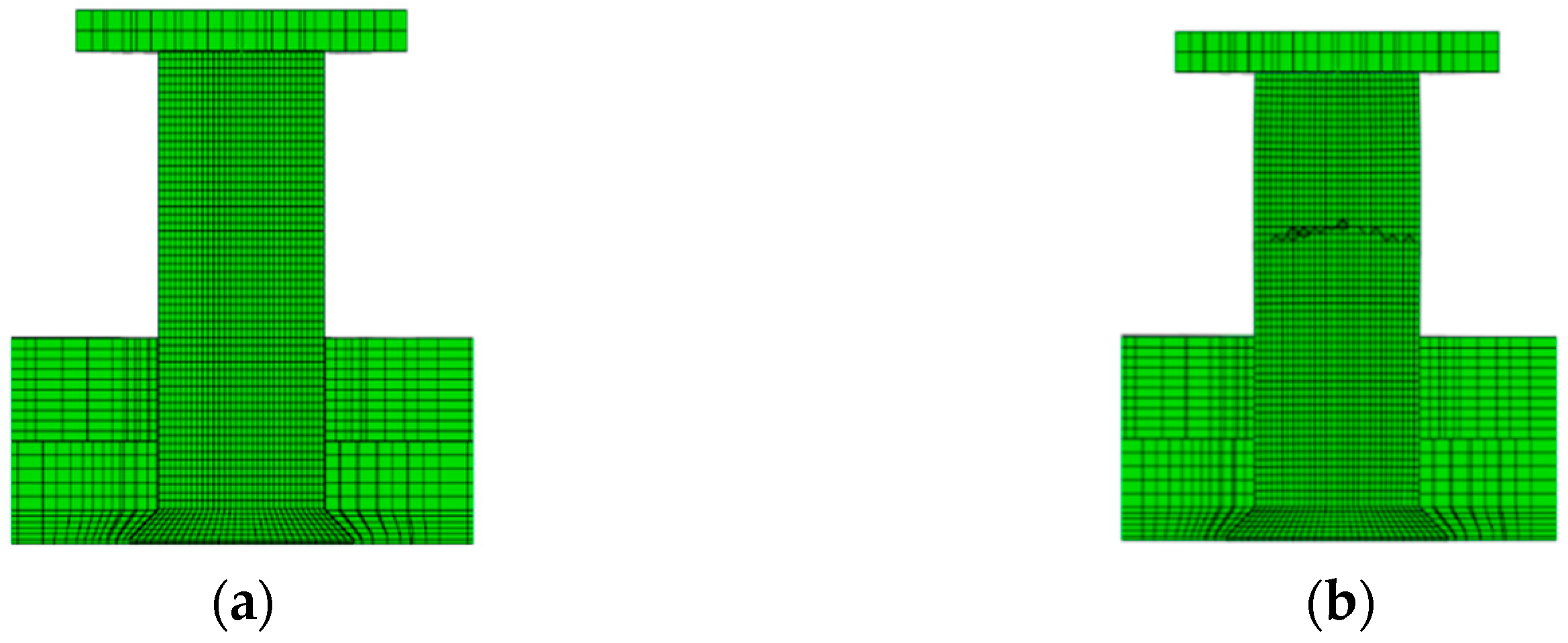
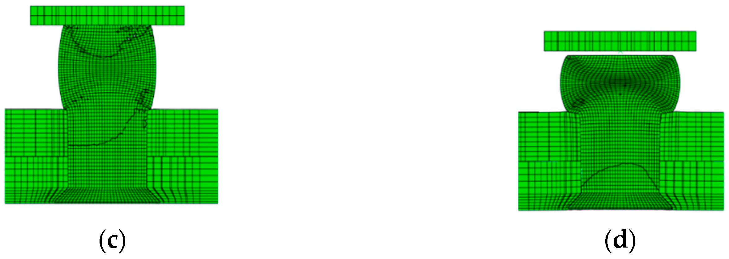
Funding

This research was funded by National Natural Science Foundation of China (No. 51775495), key projects of the National Natural Science Foundation of China (No. 91748204), and Youth Funds of the State Key Laboratory of Fluid Power and Mechatronic Systems (Zhejiang University) (No. SKLoFP_QN_1802).

Data Availability Statement

No new data were created or analyzed in this study. Data sharing is not applicable to this article.

Conflicts of Interest

The authors declare no conflict of interest.

References

  1. Gagg, C.R.; Lewis, P.R. In-Service Fatigue Failure of Engineered Products and Structures—Case Study Review. Eng. Fail. Anal. 2009, 16, 1775–1793. [Google Scholar] [CrossRef]
  2. Li, G.; Shi, G.; Bellinger, N.C. Residual Stress/Strain in Three-Row, Countersunk, Riveted Lap Joints. J. Aircr. 2007, 44, 1275–1285. [Google Scholar] [CrossRef]
  3. Li, G.; Shi, G.; Bellinger, N.C. Studies of Residual Stress in Single-Row Countersunk Riveted Lap Joints. J. Aircr. 2006, 43, 592–599. [Google Scholar] [CrossRef]
  4. Bedair, O. Stress Field Characteristics of Eccentrically Loaded Aircraft Spliced Joints. Appl. Math. Model. 2012, 36, 4543–4556. [Google Scholar] [CrossRef]
  5. Skorupa, M.; Skorupa, A.; Machniewicz, T.; Korbel, A. Effect of Production Variables On the Fatigue Behaviour of Riveted Lap Joints. Int. J. Fatigue 2010, 32, 996–1003. [Google Scholar] [CrossRef]
  6. Naarayan, S.S.; Kumar, D.M.G.P.; Chandra, S. Implication of Unequal Rivet Load Distribution in the Failures and Damage Tolerant Design of Metal and Composite Civil Aircraft Riveted Lap Joints. Eng. Fail. Anal. 2009, 16, 2255–2273. [Google Scholar] [CrossRef]
  7. Huang, W.; Wang, T.; Garbatov, Y.; Guedes Soares, C. Fatigue Reliability Assessment of Riveted Lap Joint of Aircraft Structures. Int. J. Fatigue 2012, 43, 54–61. [Google Scholar] [CrossRef]
  8. Liao, M.; Shi, G.; Xiong, Y. Analytical Methodology for Predicting Fatigue Life Distribution of Fuselage Splices. Int. J. Fatigue 2001, 23S, S177–S185. [Google Scholar] [CrossRef]
  9. Aman, F.; Cheraghi, S.H.; Krishnan, K.K.; Lankarani, H. Study of the Impact of Riveting Sequence, Rivet Pitch, and Gap Between Sheets On the Quality of Riveted Lap Joints Using Finite Element Method. Int. J. Adv. Manuf. Tech. 2013, 67, 545–562. [Google Scholar] [CrossRef]
  10. Atre, A.; Johnson, W.S. Effect of Interference On the Mechanics of Load Transfer in Aircraft Fuselage Lap Joints. J. Eng. Mater.-T. Asme 2007, 129, 356–366. [Google Scholar] [CrossRef]
  11. Cheraghi, S.H. Effect of Variations in the Riveting Process On the Quality of Riveted Joints. Int. J. Adv. Manuf. Tech. 2008, 39, 1144–1155. [Google Scholar] [CrossRef]
  12. Manes, A.; Giglio, M.; Vigano, F. Effect of Riveting Process Parameters On the Local Stress Field of a T-Joint. Int. J. Mech. Sci. 2011, 53, 1039–1049. [Google Scholar] [CrossRef]
  13. Liu, J.; Li, H.; Bi, Y.; Dong, H.; Ke, Y. Influence of the Deformation of Riveting-Side Working Head On Riveting Quality. Int. J. Adv. Manuf. Tech. 2019, 102, 4137–4151. [Google Scholar] [CrossRef]
  14. Liu, J.; Zhao, A.; Ke, Z.; Zhu, Z.; Bi, Y. Influence of Rivet Diameter and Pitch On the Fatigue Performance of Riveted Lap Joints Based On Stress Distribution Analysis. Materials 2020, 13, 3625. [Google Scholar] [CrossRef] [PubMed]
  15. Nowell, D.; Hills, D.A. Crack Initiation Criteria in Fretting Fatigue. Wear 1990, 136, 329–343. [Google Scholar] [CrossRef]
  16. Yuan, X.; Yue, Z.F.; Yan, W.Z.; Wen, S.F.; Li, L. Experimental and Analytical Investigation of Fatigue and Fracture Behaviors for Scarfed Lap Riveted Joints with Different Lap Angle. Eng. Fail. Anal. 2013, 33, 505–516. [Google Scholar] [CrossRef]
  17. Szolwinski, M.P.; Farris, T.N. Linking Riveting Process Parameters to the Fatigue Performance of Riveted Aircraft Structures. J. Aircraft 2000, 37, 130–137. [Google Scholar] [CrossRef]
  18. Urban, M.R. Analysis of the Fatigue Life of Riveted Sheet Metal Helicopter Airframe Joints. Int. J. Fatigue 2003, 25, 1013–1026. [Google Scholar] [CrossRef]
  19. Szymczyk, E.; Jachimowicz, J.; Slawinski, G.; Derewonko, A. Influence of Technological Imperfections on Residual Stress Fields in Riveted Joints. In Procedia Engineering; Chapter’ MESOMECHANICS; Korsunsky, A.M., Dini, D., Sih, G.C., Eds.; Elsevier: Amsterdam, The Netherlands, 2009; pp. 59–62. [Google Scholar]
  20. Lei, C.; Bi, Y.; Li, J.; Ke, Y. Effect of Riveting Parameters On the Quality of Riveted Aircraft Structures with Slug Rivet. Adv. Mech. Eng. 2017, 9, 168781401773471. [Google Scholar] [CrossRef]
Figure 1. Riveting deformation process: (a) stage 1 of riveting process; (b) stage 2 of riveting process; (c) stage 3 of riveting process; (d) stage 4 of riveting process.
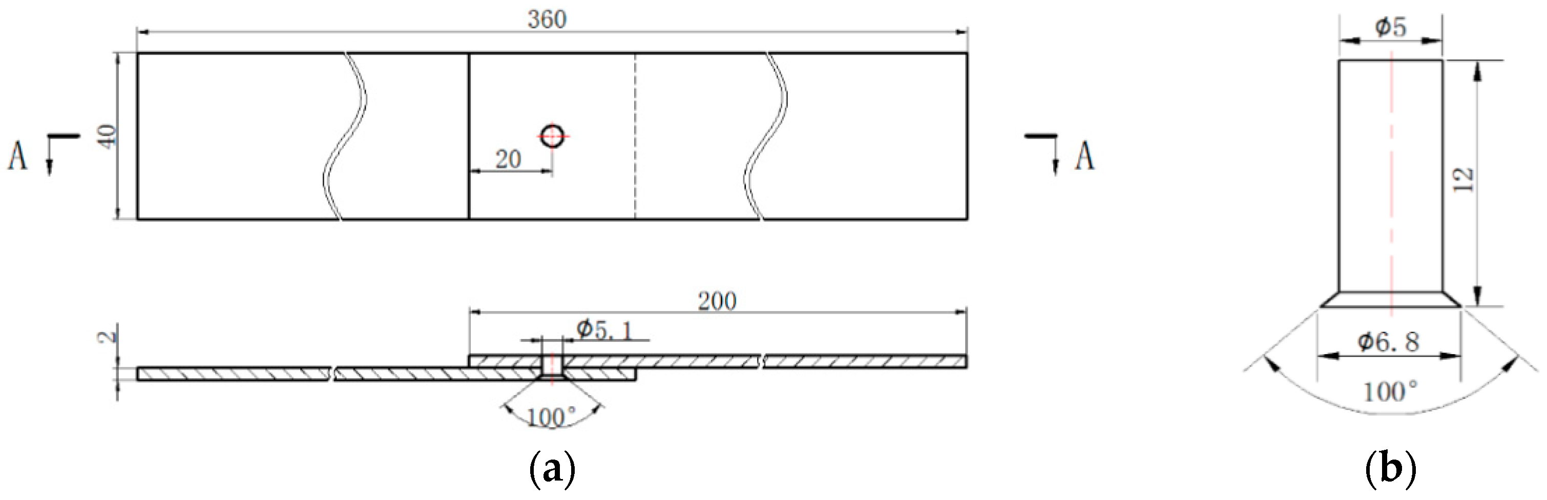
Coatings 11 00236 g001aCoatings 11 00236 g001b
Figure 2. Schematic diagram of riveted lap joint structure and size: (a) the structure and size of the joint plate; (b) the structure and size of the countersunk rivet.
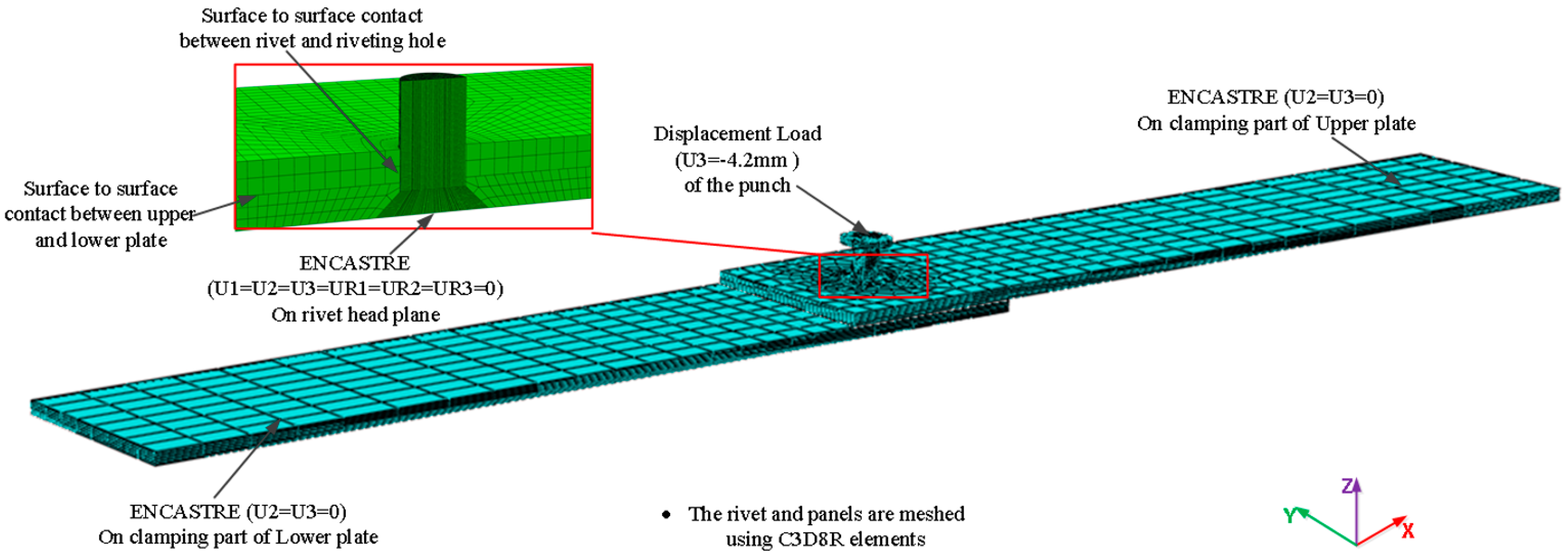
Coatings 11 00236 g002
Figure 3. Riveting model after finite element meshing.
Coatings 11 00236 g003
Figure 4. Mises stress distribution of riveted parts (unit: MPa) (global).
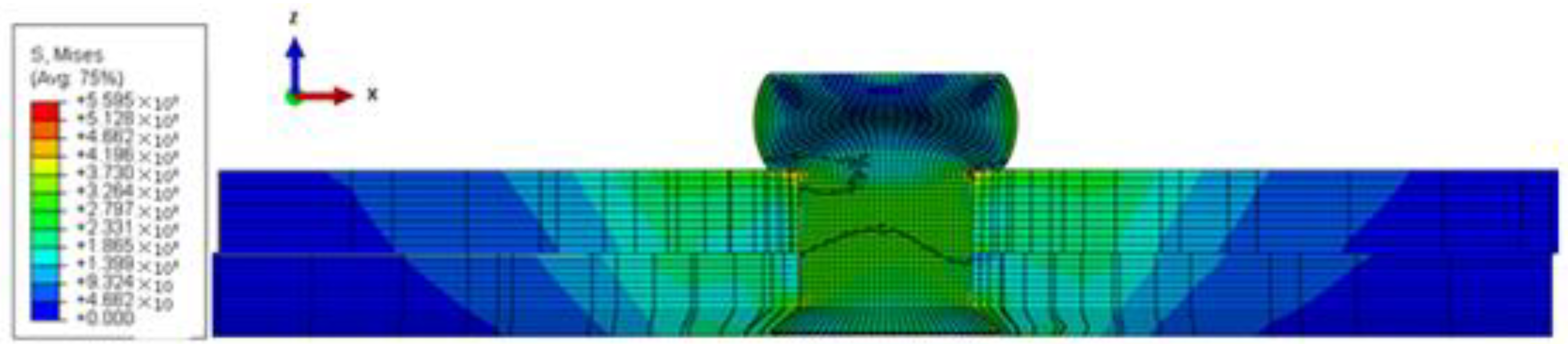
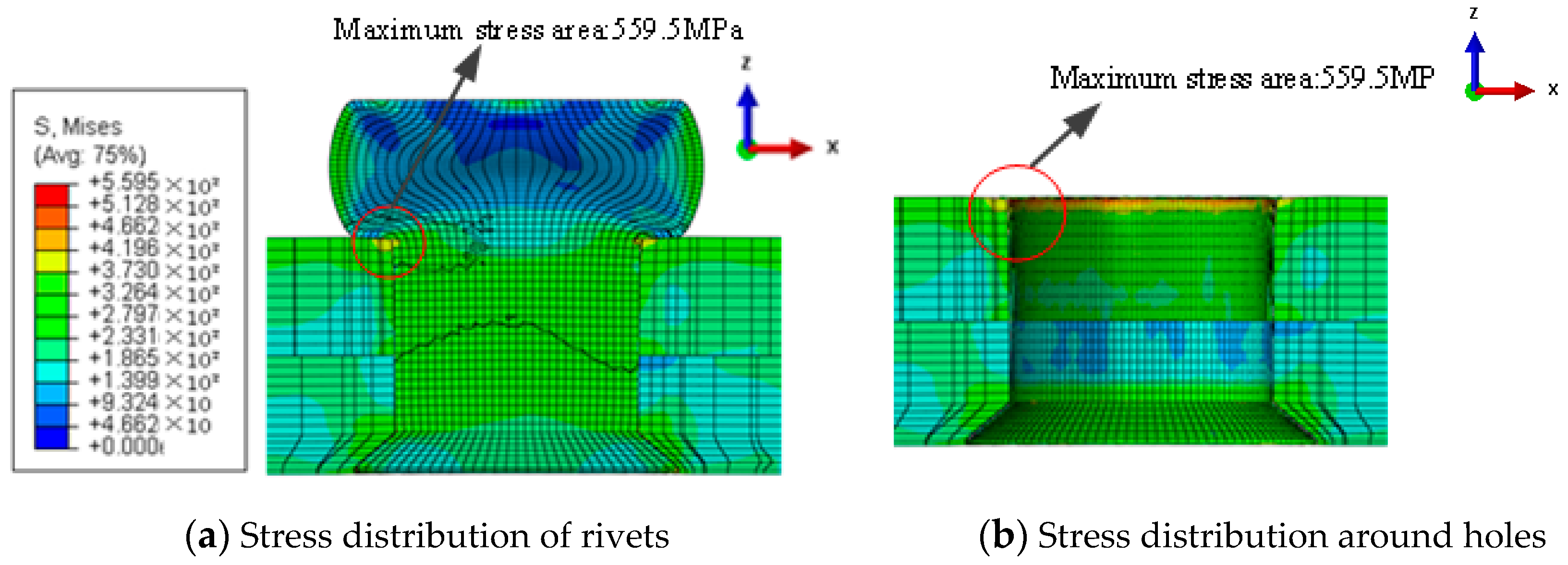
Coatings 11 00236 g004
Figure 5. Mises stress distribution of riveted parts (unit: MPa) (local).
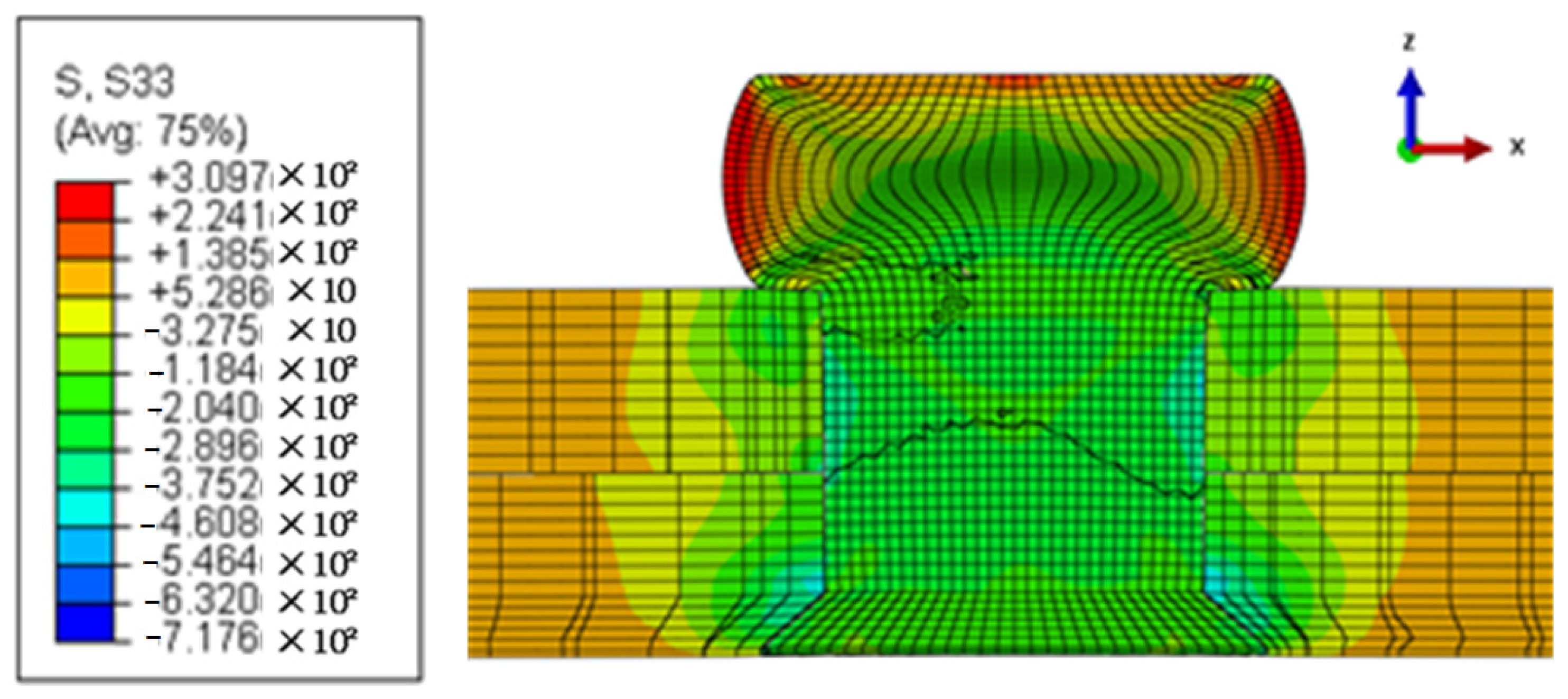
Coatings 11 00236 g005
Figure 6. Residual circumferential stress around rivet and hole (unit: MPa).
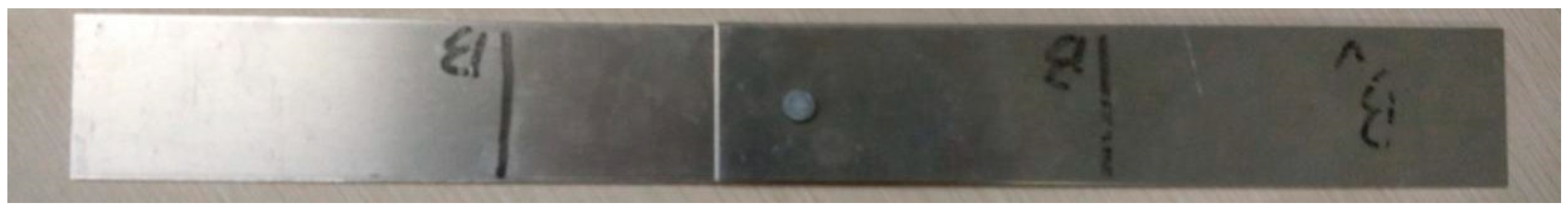
Coatings 11 00236 g006
Figure 7. Riveting test piece.
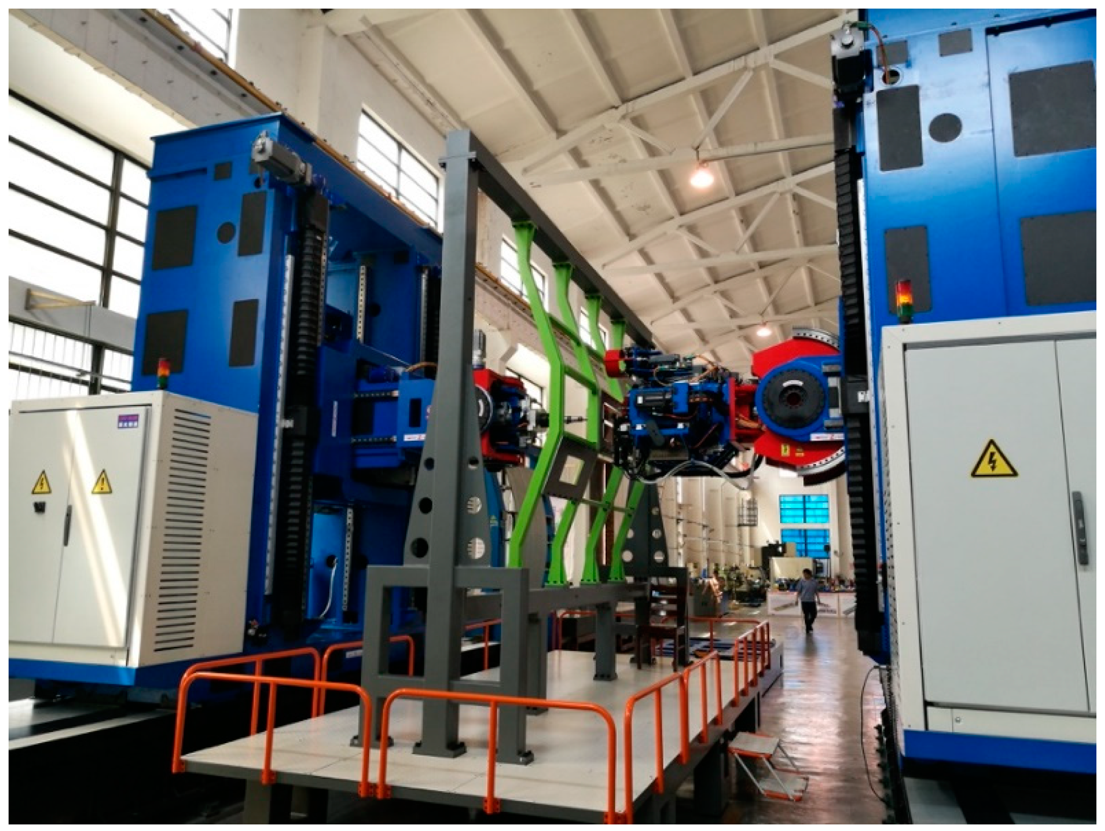
Coatings 11 00236 g007
Figure 8. Automatic drilling and riveting machine pressure riveting test.
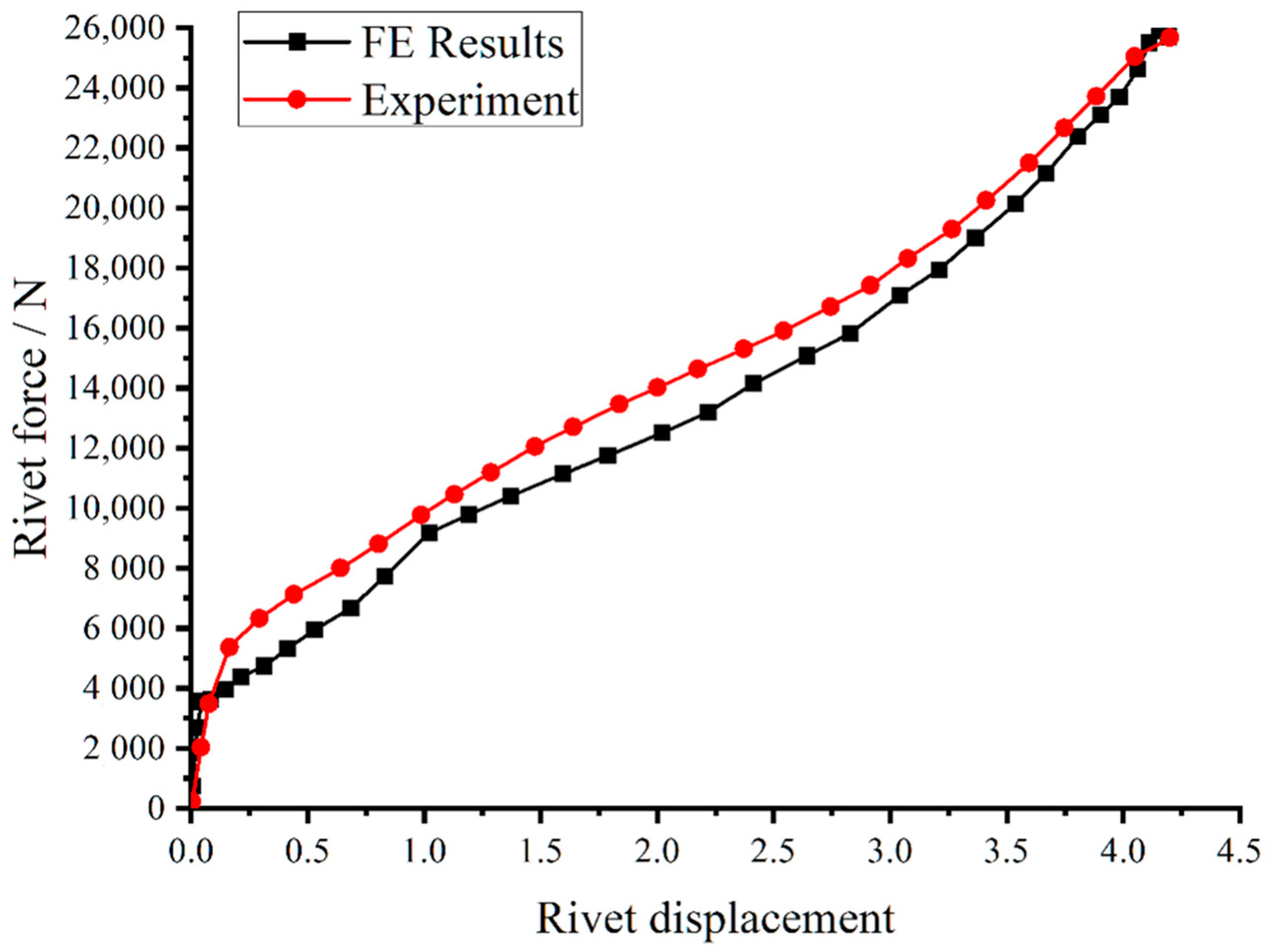
Coatings 11 00236 g008
Figure 9. Riveting force–displacement comparison curve obtained by finite element simulation and experiment.
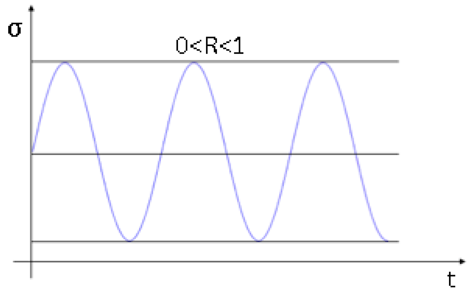
Coatings 11 00236 g009
Figure 10. Stress cycle diagram under fluctuation cycle.
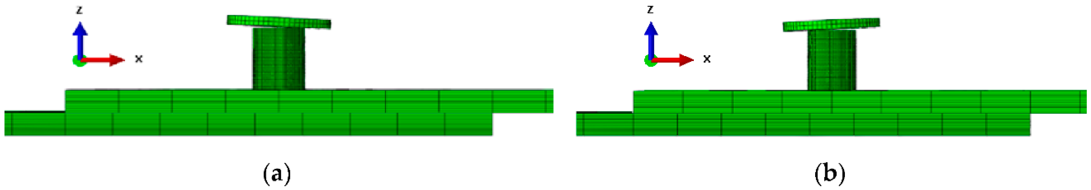
Coatings 11 00236 g010
Figure 11. Schematic diagram of the finite element model of different riveting angles and directions: (a) 0-3: a pressure riveting model with the punch deflected by 3° under the direction of 0°; (b) 180-3: a pressure riveting model with the punch deflected by 3° under the direction of 180°.
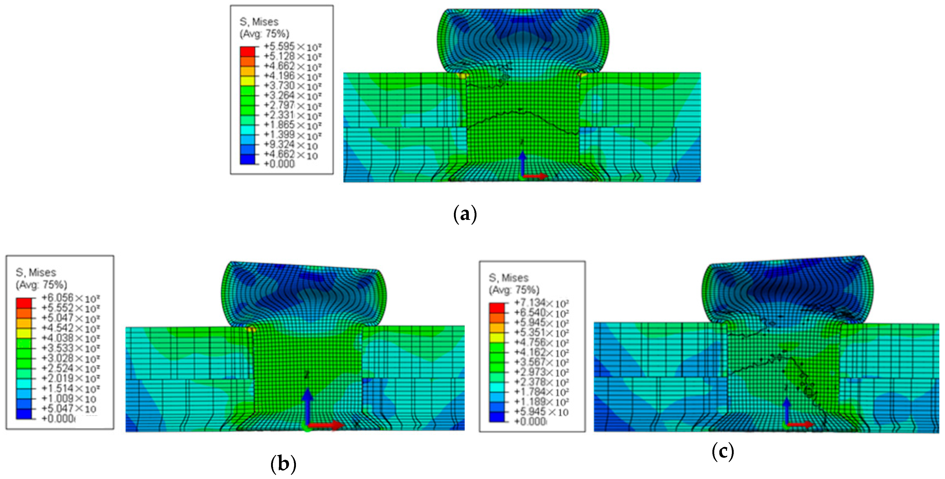
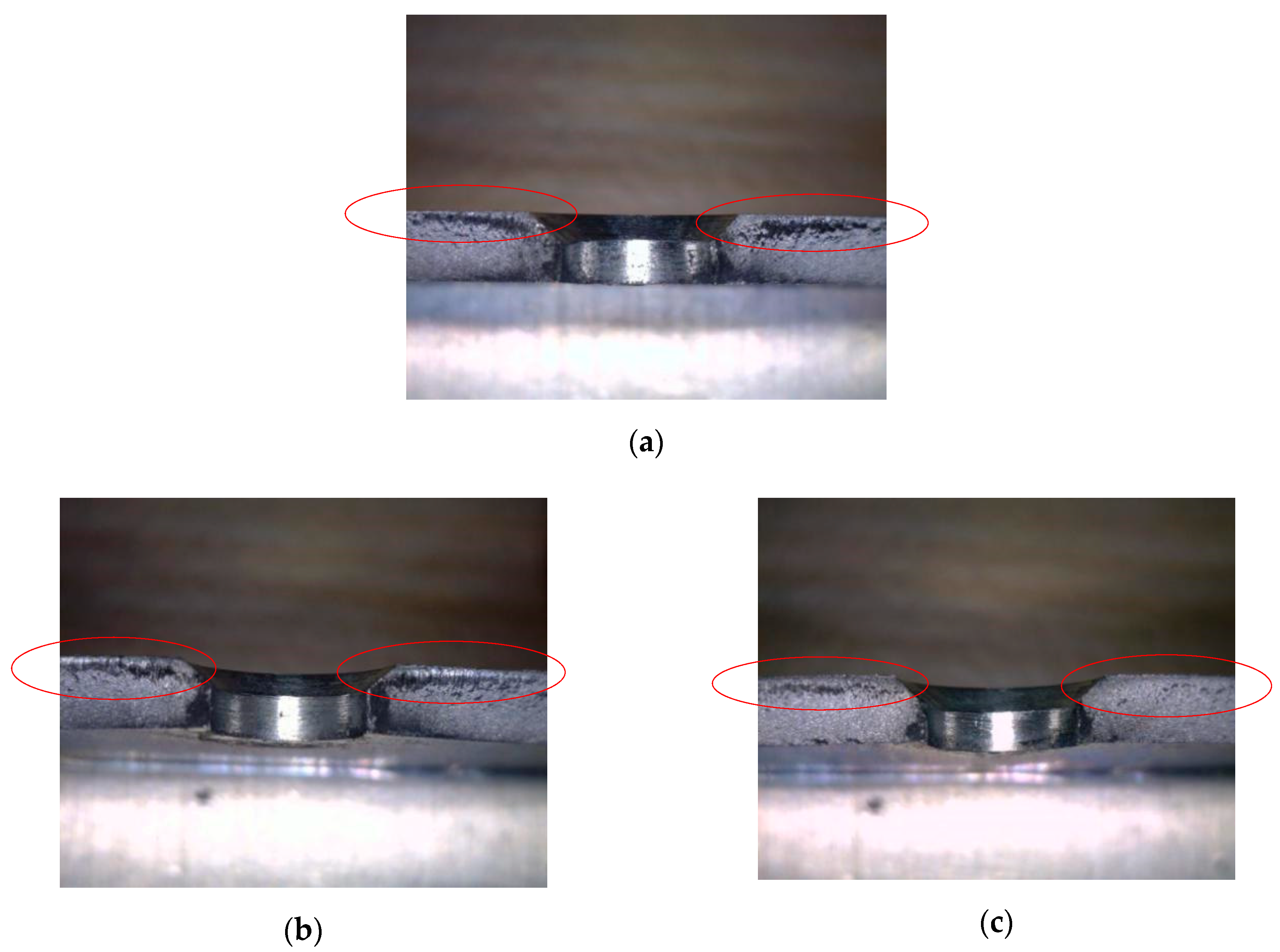
Coatings 11 00236 g011
Figure 12. Simulation results of riveted parts after pressing riveting at different angles in the same direction (0°) (unit: MPa): (a) the reference deformation and stress result of the punch at 0° when the punch is not deflected; (b) the deformation and stress result of the punch pressing down at an angle of 3° in the direction of 0°; (c) the deformation and stress result of the punch pressing down at an angle of 3° in the direction of 180°.
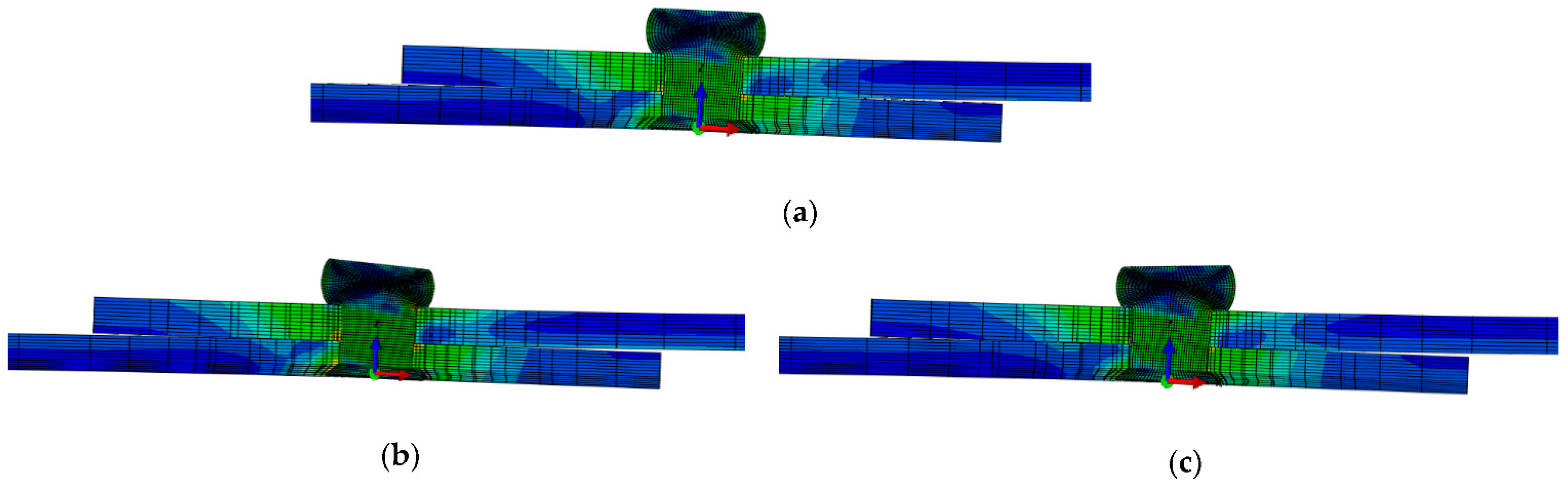
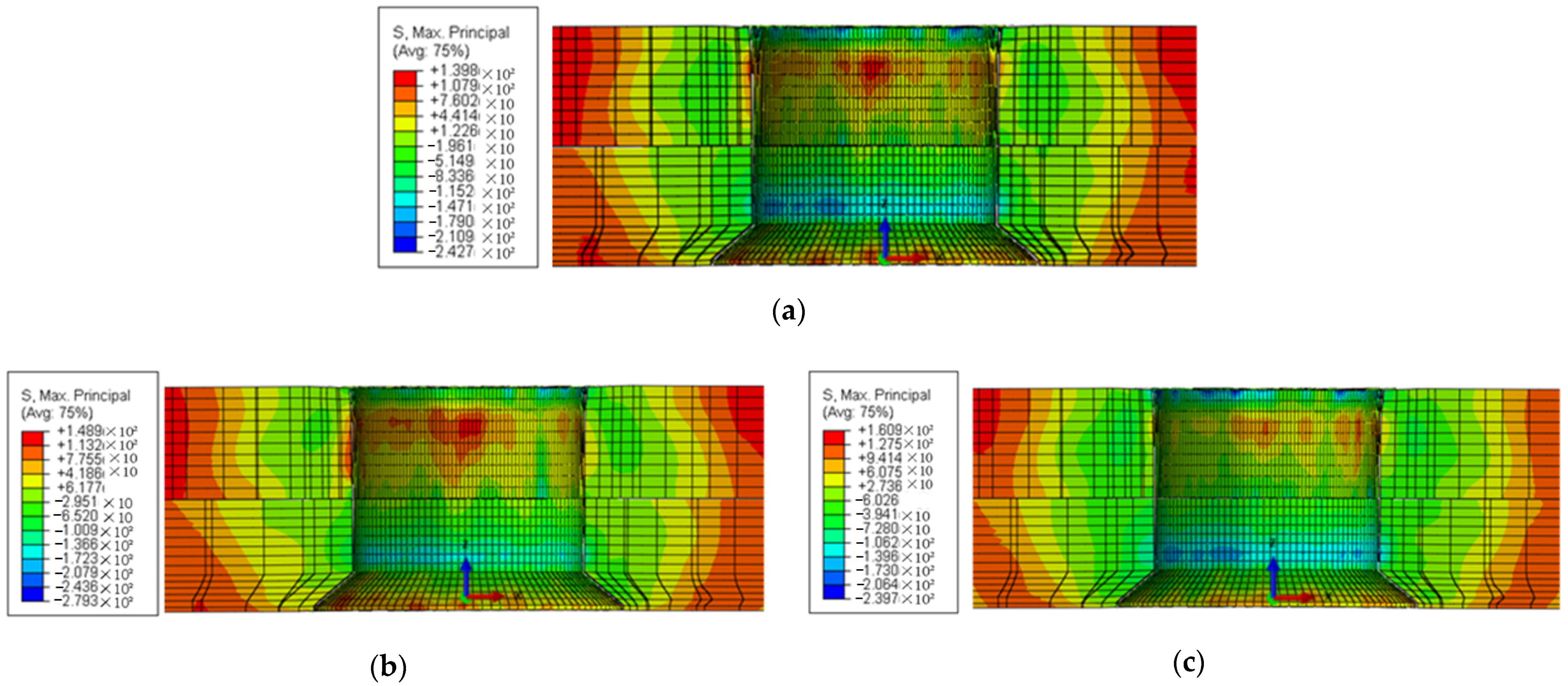
Coatings 11 00236 g012
Figure 13. Simulation results of riveted piece after transverse stretching: (a) the reference deformation and stress result of the punch at 0° when the punch is not deflected (0-0); (b) the deformation and stress result of the punch pressing down at an angle of 3° in the direction of 0° (0-3); (c) the deformation and stress result of the punch pressing down at an angle of 3° in the direction of 180° (180-3).
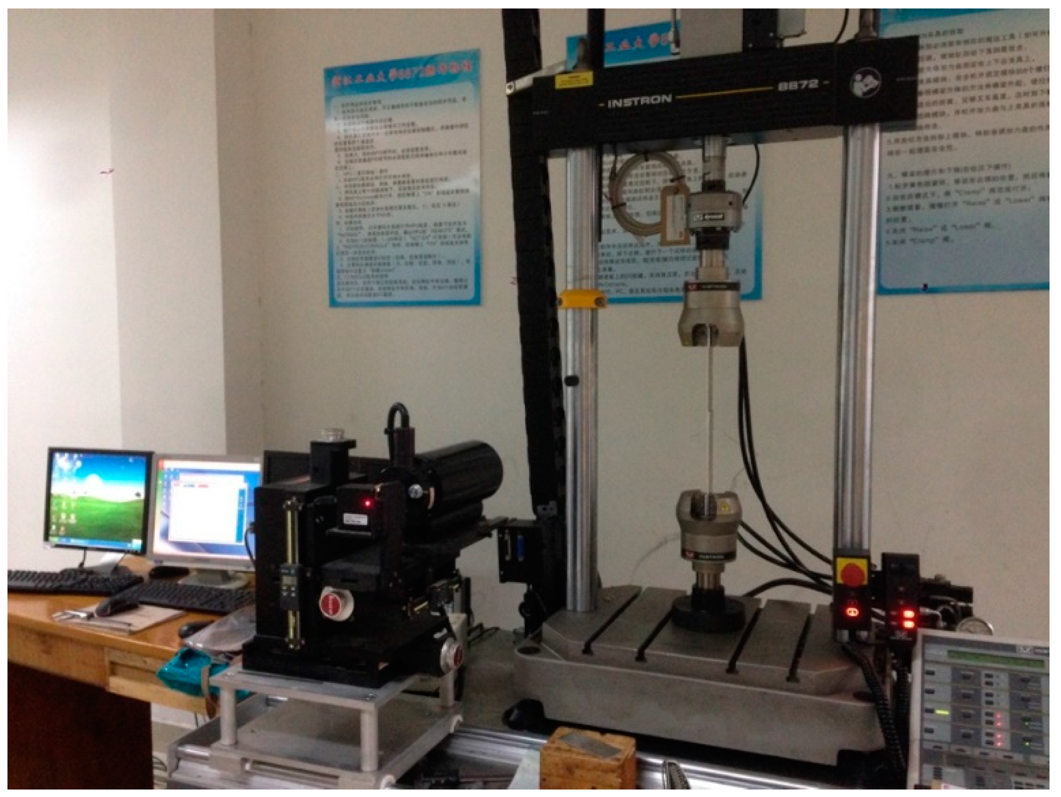
Coatings 11 00236 g013
Figure 14. Schematic diagram of fatigue test system: Instron 8872 Fatigue Test System.
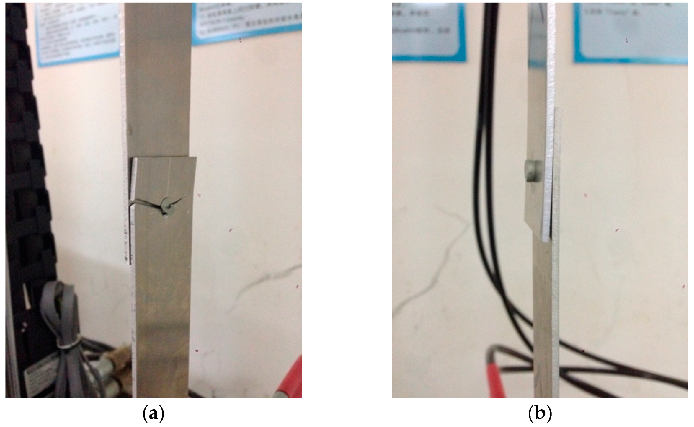
Coatings 11 00236 g014
Figure 15. High-cycle and low-cycle fatigue test results of riveted lap joints: (a) plate fractures with high-cycle fatigue failure; (b) rivet fracture with low-cycle fatigue failure.
Coatings 11 00236 g015
Figure 16. Fatigue fracture section of riveted lap joint: (a) fatigue fracture section of 0° standard part (0-0); (b) fatigue fracture section of riveted lap joint with 1° in the 0° direction (0-1); (c) fatigue fracture section of riveted lap joint with 1° in the 180° direction (180-1).
Coatings 11 00236 g016
Figure 17. Distribution diagram of maximum principal stress around the hole of riveted parts (unit: MPa): (a) distribution of maximum principal stress of 0° standard part (0-0); (b) distribution of maximum principal stress of riveted parts of 1° in the 0° direction (0-1); (c) distribution of maximum principal stress of riveted parts of 1° in the 180° direction (180-1).
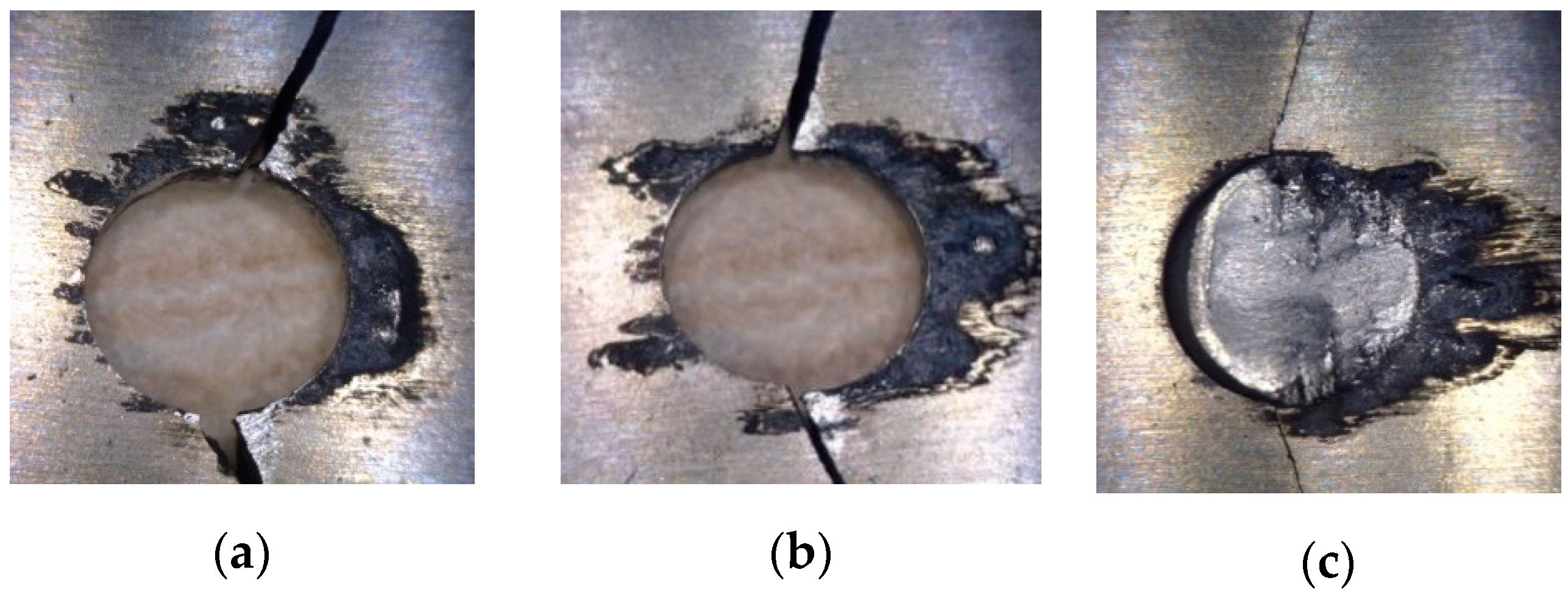
Coatings 11 00236 g017
Figure 18. Fatigue failure morphology of riveted lap joints at different riveting angles: (a) fatigue failure morphology of 0° standard part (0-0); (b) fatigue failure morphology of riveted joints of 1° in the 0° direction (0-1); (c) fatigue failure morphology of riveted joints of 2° in the 0° direction (0-2).
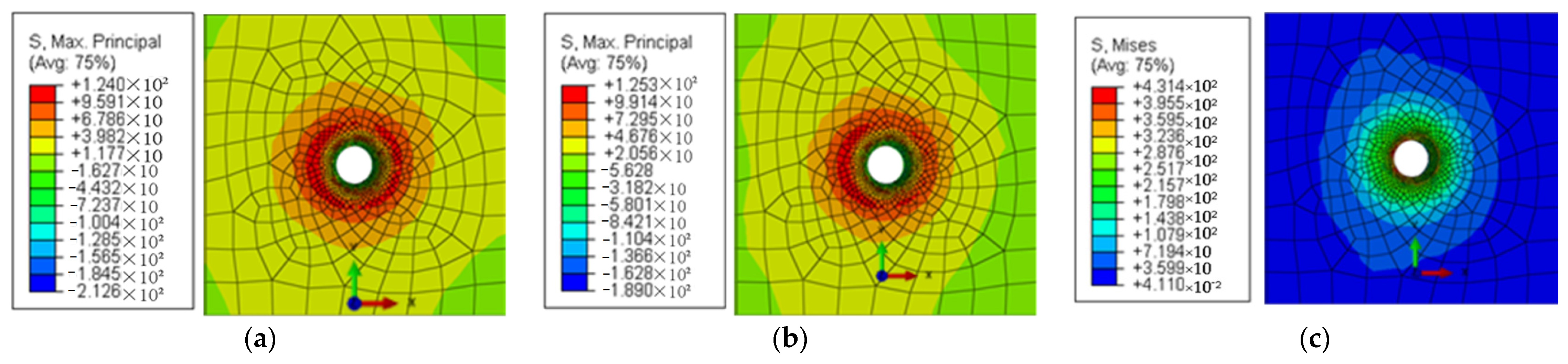
Coatings 11 00236 g018
Figure 19. Distribution diagram of maximum principal stress of riveted joints of different riveting angles (unit: MPa): (a) distribution of maximum principal stress of 0° standard part (0-0); (b) distribution of maximum principal stress of riveted parts of 1° in the 0° direction (0-1); (c) distribution of maximum principal stress of 2° in the 0° direction (0-2).
Coatings 11 00236 g019
Figure 20. Fatigue failure morphology of riveted lap joints in different riveting directions: (a) fatigue failure morphology of riveted joints of 1° in the 0° direction (0-1); (b) fatigue failure morphology of riveted joints of 1° in the 180° direction (180-1); (c) fatigue failure morphology of riveted joints of 2° in the 0° direction (0-2); (d) fatigue failure morphology of riveted joints of 2° in the 180° direction (180-2).
Coatings 11 00236 g020
Figure 21. Distribution diagram of maximum principal stress of riveted joints in different riveting directions (unit: MPa): (a) distribution of maximum principal stress of riveted joints of 1° in the 0° direction (0-1); (b) distribution of maximum principal stress of riveted joints of 1° in the 180° direction (180-1); (c) distribution of maximum principal stress of 2° in the 0° direction (0-2); (d) distribution of maximum principal stress of 2° in the 180° direction (180-2).
Coatings 11 00236 g021
Figure 22. High-cycle fatigue failure and low-cycle fatigue failure of riveted joints of different riveting angles: (a) comparison of high-cycle fatigue and low-cycle fatigue failures of 0° standard part (0-0); (b) comparison of high-cycle fatigue and low-cycle fatigue failures of riveted parts of 1° in the 0° direction (0-1); (c) comparison of high-cycle fatigue and low-cycle fatigue failures of riveted parts of 2° in the 0° direction (0-2).
Coatings 11 00236 g022
Figure 23. Stress distribution diagram of rivet under shearing force (unit: MPa): (a) stress distribution of rivet of 0° standard part (0-0); (b) stress distribution of rivet of joints of 1° in the 0° direction (0-1); (c) stress distribution of rivet of joints of 2° in the 0° direction (0-2); (d) stress distribution of rivet of joints of 1° in the 180° direction (180-1); (e) stress distribution of rivet of joints of 2° in the 180° direction (180-2).
Coatings 11 00236 g023
Table 1. Material parameters of 2117-T4 aluminum alloy rivets.
Material Parameter2117-T4 Aluminum Alloy Rivets
Density, ρ2830 Kg/m3
Young’s modulus, E74 GPa
Poisson’s ratio, ν0.33
Yield stress, σS172 MPa
Strength coefficient, C 1(0.02 ≤ εtrue ≤ 0.10)544 MPa
Strength coefficient, C 1(0.10 ≤ εtrue ≤ 1.0)551 MPa
Hardening exponent, m 1(0.02 ≤ εtrue ≤ 0.10)0.23
Hardening exponent, m 1(0.10 ≤ εtrue ≤ 1.0)0.15
1 The parameters C and m satisfy the above Formula (1).
Table 2. Material parameters of 7050 aluminum alloy plates.
Material Parameter7050 Aluminum Alloy Rivets
Density, ρ2690 Kg/m3
Young’s modulus, E71.7 GPa
Poisson’s ratio, ν0.33
Yield stress, σS310 MPa
Strength coefficient, C 1y ≤ εtrue ≤ 0.02)676 MPa
Strength coefficient, C 1(0.02 ≤ εtrue ≤ 0.1)745 MPa
Hardening exponent, m 1y ≤ εtrue ≤ 0.02)0.14
Hardening exponent, m 1(0.02 ≤ εtrue ≤ 0.1)0.164
1 The parameters C and m satisfy the above Formula (1).
Table 3. Driven head size data comparison between simulation and riveting test.
ParametersData
Diameter of driven head from simulation 7.843 mm
Diameter of driven head from test8.021 mm
Driven head diameter difference0.178 mm
Deviation2.2%
Table 4. Fatigue life of riveted lap joints at different riveting angles.
Riveting Angle
High-cycle fatigue life (cycle)163,793212,862144,572
Low-cycle fatigue life (cycle)11,21213,03914,161
Table 5. High-cycle fatigue life of riveted joints at different riveting angles and directions.
Riveting Directions
High-cycle fatigue life of 0° direction (cycle)163,793212,862144,572
High-cycle fatigue life of 180° direction (cycle)131,87887,141
Table 6. Low-cycle fatigue life of riveted joints at different riveting angles and directions.
Riveting Angles
Low-cycle fatigue life of 0° direction (cycle)11,21213,03914,161
Low-cycle fatigue life of 180° direction (cycle)10,46913,453
Table 7. Maximum shear stress of rivet at different riveting angles and directions.
Riveting Angles
Maximum shear stress of 0° direction (MPa)616.4602.4588.1
Maximum shear stress of 180° direction (MPa)625.3631.4
Publisher’s Note: MDPI stays neutral with regard to jurisdictional claims in published maps and institutional affiliations.

