Article

Structure and Tribological Properties of Ni–Cr–Al-Based Gradient Coating Prepared by Detonation Spraying

1
Research Center «Surface Engineering and Tribology», Sarsen Amanzholov East Kazakhstan University, Ust-Kamenogorsk 070000, Kazakhstan
2
PlasmaScience LLP, Ust-Kamenogorsk 070000, Kazakhstan
*
Author to whom correspondence should be addressed.
Coatings 2021, 11(2), 218; https://doi.org/10.3390/coatings11020218
Submission received: 27 December 2020 / Revised: 9 February 2021 / Accepted: 11 February 2021 / Published: 12 February 2021
(This article belongs to the Special Issue Corrosion Science and Surface Engineering)

Abstract

:
In this paper, Ni–Cr–Al coatings were deposited using the detonation spraying method. The aim was to investigate how technological parameters influence coating structure formation, phase composition and tribological performances. We observed that the degree to which the barrel is filled with an O2/C2H2 gas mixture strongly influences the chemical composition of manufactured coatings. High degrees of barrel filling led to a decrease in aluminum content in the coating. Filling degrees of 40% and 50% produced sprayed coatings in which only Ni–Cr phases could be found. When the filling degree was reduced up to 25%, Ni–Al phases began to form in the sprayed coatings. Gradient Ni–Cr–Al coatings were produced by gradually reducing the filling degree from 50% to 25%. These coatings are characterized by Ni–Cr near the substrate level with Ni–Cr and Ni–Al phases at higher levels. The results obtained confirm that gradient Ni–Cr–Al coatings exhibit high hardness as well as good wear resistance.

1. Introduction

High-velocity spraying technologies have been intensively investigated of late because of their high-efficiency and properties that allow the development of processes that are easy to automate and apply to practically unlimited sizes of coated surfaces [1,2,3]. These methods can significantly expand the possibilities of conventional flame powder spraying in the field of wear and corrosion protection coatings.
In the area of thermal spray technologies, high-velocity spraying can be realized through detonation, plasma and high-velocity oxygen–fuel (HVOF) spraying, high-velocity air–fuel (HVAF) and warm spraying [3,4,5,6,7]. Detonation spraying, in particular, offers great promise. In this method, a spark plug ignites an explosive reaction and detonates a gas mixture (mainly oxygen and acetylene) that melts and accelerates powder particles. Maximum powder particle velocity can reach as high as 1000 m/s [8,9]. Special attention has been paid to the deposition of composite ceramic, metal–ceramic, and bio-ceramic coatings [10,11,12]. MCrAl coatings (where M = Ni, Co or both) are of particular interest from the point of view of wear and corrosion resistance, but the strength and plasticity of such coatings must be assured as a function of the substrate material [13,14,15,16]. MCrAl-based coatings are widely used as heat-protective coatings that form a protective oxide layer during high-temperature exploitation. Resistance to high-temperature oxidation is one of their most important properties. Al and Cr are important components in MCrAl coatings that protect critical turbine components under oxidation and hot corrosion conditions. Undue additions of Al and Cr can lead to the formation of higher amounts of Ni3Al (γ′) and rich Ni γ-phases, which degrade fatigue life [17].
Detonation coatings properties can be improved by depositing various materials in several layers, thereby producing coatings with unique properties [18]. It is also possible to produce a feedstock gradient coating whose structure and consequently properties change with thickness. Graded coatings exhibit lower stresses at the substrate-coating interface and can be designed for specific work conditions [19]. In recent decades, research for improving the oxidation resistance of MCrAl coatings has mainly focused on modifying the MCrAl coatings. A principal research direction has been the production of gradient coatings that have high adhesive strength, hardness, corrosion resistance, and wear resistance [17,20]
The present study investigates the influence of the technological parameters on the coatings’ structure formation, phase composition and tribological performances. We also examine the feasibility of producing Ni–Cr–Al gradient coatings using the detonation spraying method.

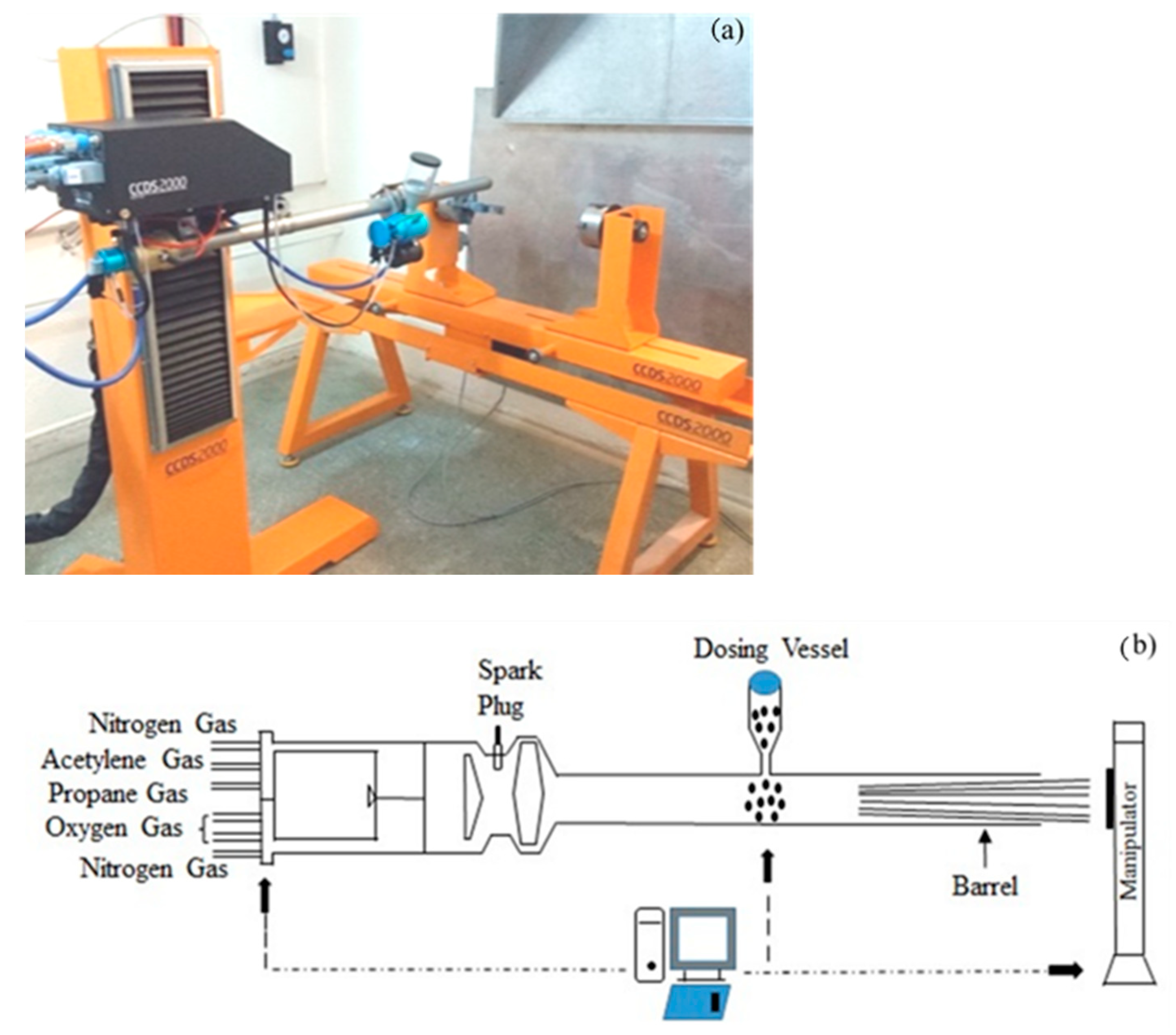
2. Materials and Methods

We carried out detonation spraying using the CCDS2000 (LIH SB RAS, Novosibirsk, Russia ) setup that is described in [21,22]. Figure 1 presents a general view of the setup and a schematic illustrating the detonation spraying principle. The gun barrel is filled with gases using a high-precision computer-controlled gas distribution system. The process begins by filling the barrel with a carrier gas.
We sandblasted the substrates before spraying in order to increase surface roughness (Ra = 1.25 µm). The feedstock was a mixture of 80 wt % NiCr powder (Ni20Cr80) and 20 wt % of Al (99.99% purity) [23]. Nominal powder particle size ranged between 30 and 45 µm. A PULVERISETTE 23 planetary ball mill was used for preliminary powder mixture activation. The mechanical activation time was 2 h with a frequency of 30 Hz.
The coatings were sprayed onto 12Kh1MF (DIN 14MoV63) ferrite-perlite steel substrates with 50 mm diameter and 3 mm thickness. Table 1 gives the chemical composition of the 12Kh1MF steel.
We produced coatings based on Ni–Cr–Al for a range of barrel filling volumes using an acetylene–oxygen mixture as the fuel gas. As the proportion of explosive mixture increases (from 25% to 60% of the barrel volume), the temperature to which the particles are heated inside the barrel increases. In addition, for lower particle velocities, a change in the oxygen/fuel ratio from O2/C2H2 = 1.1 to O2/C2H2 can lead to an increased temperature for a given explosive mixture volume.
We chose O2/C2H2 = 1.856 as the optimal ratio that minimizes intermetalide formation resulting from incomplete combustion during spraying. Ni–Cr–Al coatings were obtained for barrel filling volumes varying from 25% to 50%. Table 2 presents the process parameters used.
We determined the phase composition of the sprayed coatings via the X-ray diffraction technique (XRD) using an X’PertPRO (Philips Corporation, Amsterdam, Netherlands) diffractometer with Cu-Kα radiation (λ = 2.2897 Å ) at a voltage of 40 kV and a current of 30 mA. The diffractograms were decoded using the HighScore program with measurements were performed in the range of 2ϴ equal to 200–900 with 0.02 step size and 0.5 s/step counting time. The surface roughness of the coatings was estimated according to GOST 2789-73 (ASTM D7127-05) using the Ra parameter by profilometer model 130 (JSC Plant PROTON, Moscow, Russia) [24]. We photographed the surface of the coatings at 5× optical magnification using a metallographic microscope (Altami MET 5S model; Altami LLC, Saint Petersburg, Russia). We studied the mechanical properties of the coatings (microhardness, nanohardness and Young’s modulus) using a PMT-3 M (LOMO, Saint Petersburg, Russia) microhardness tester and NanoScan-4D compact (FSBI TISNCM, Moscow, Russia) nanohardness tester. Microhardness was measured according to GOST 9450-76 (ASTM E384-11) [25] with a maximum load value equal to 1 N and dwell time of 10 s. Instrumental indentation, as well as elastic modulus, were measured according to the Oliver–Pharr methodology [26] using a Berkovich indenter with a maximum load equal to 100 mN (ASTM E2546-07) [27].
Tribological performances were evaluated in dry sliding tests performed on a high-temperature TRB3 (Anton Paar Srl, Peseux, Switzerland) using the standard ball-on-disc technique according to the ASTM G 133-95 and ASTM G99 standards [28,29]. A SiC coated steel ball of 3 mm diameter served as a counterpart. The tests were performed under ambient conditions, with a normal load of 10 N, the linear velocity of 3 cm/s and wear track radius of 4 mm. The friction distance was equal to 81 m. The tribological performance of the coatings were characterized by wear intensity and friction coefficient. To obtain reliable results, we carried out the test on three samples from each variant. We employed scanning electron microscopy (SEM) using backscattered electrons (BSE) at accelerated voltages of a JSM-6390LV (Jeol, Tokyo, Japan) scanning electron microscope to study the morphology of sample cross-section.

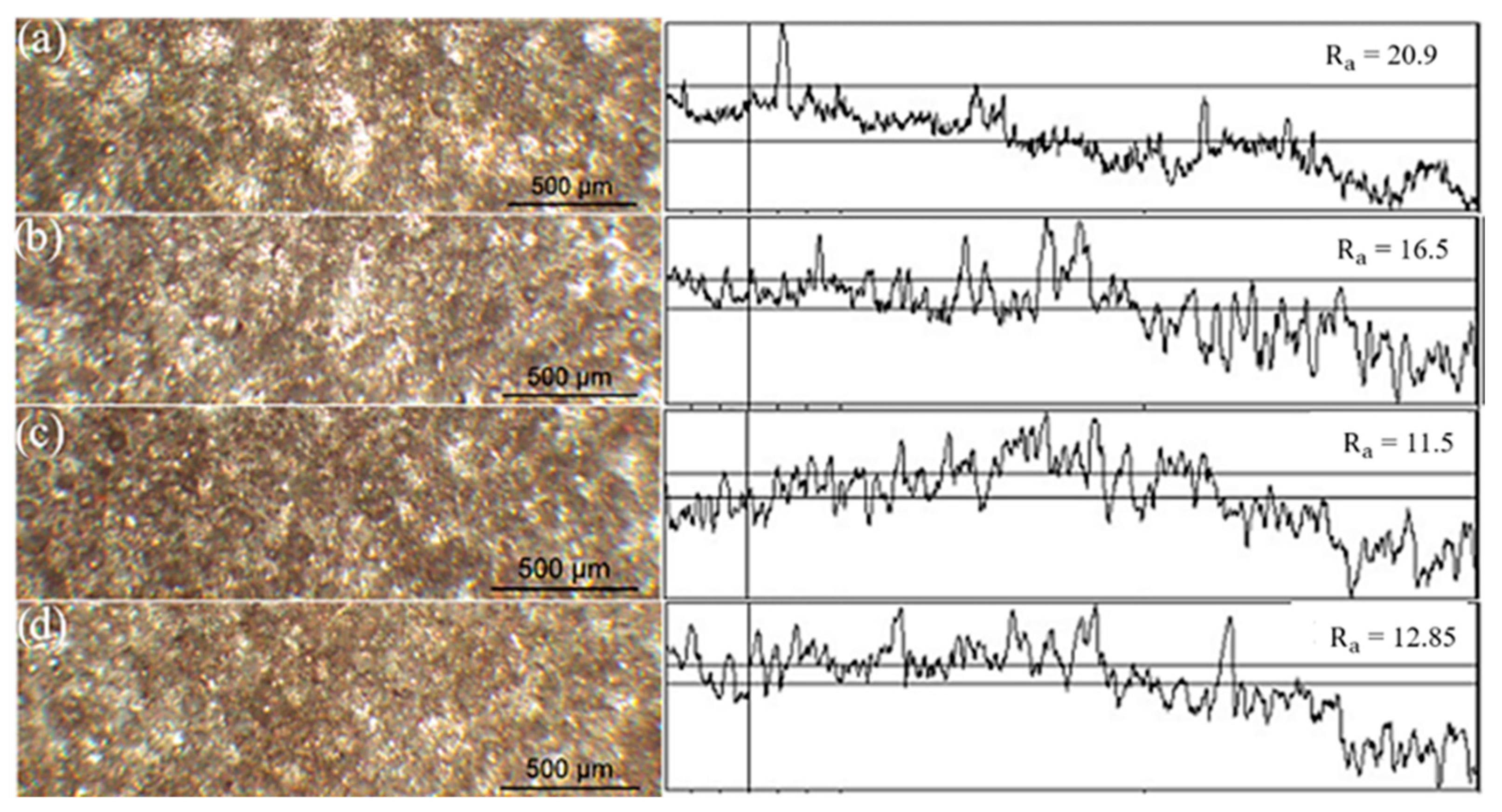
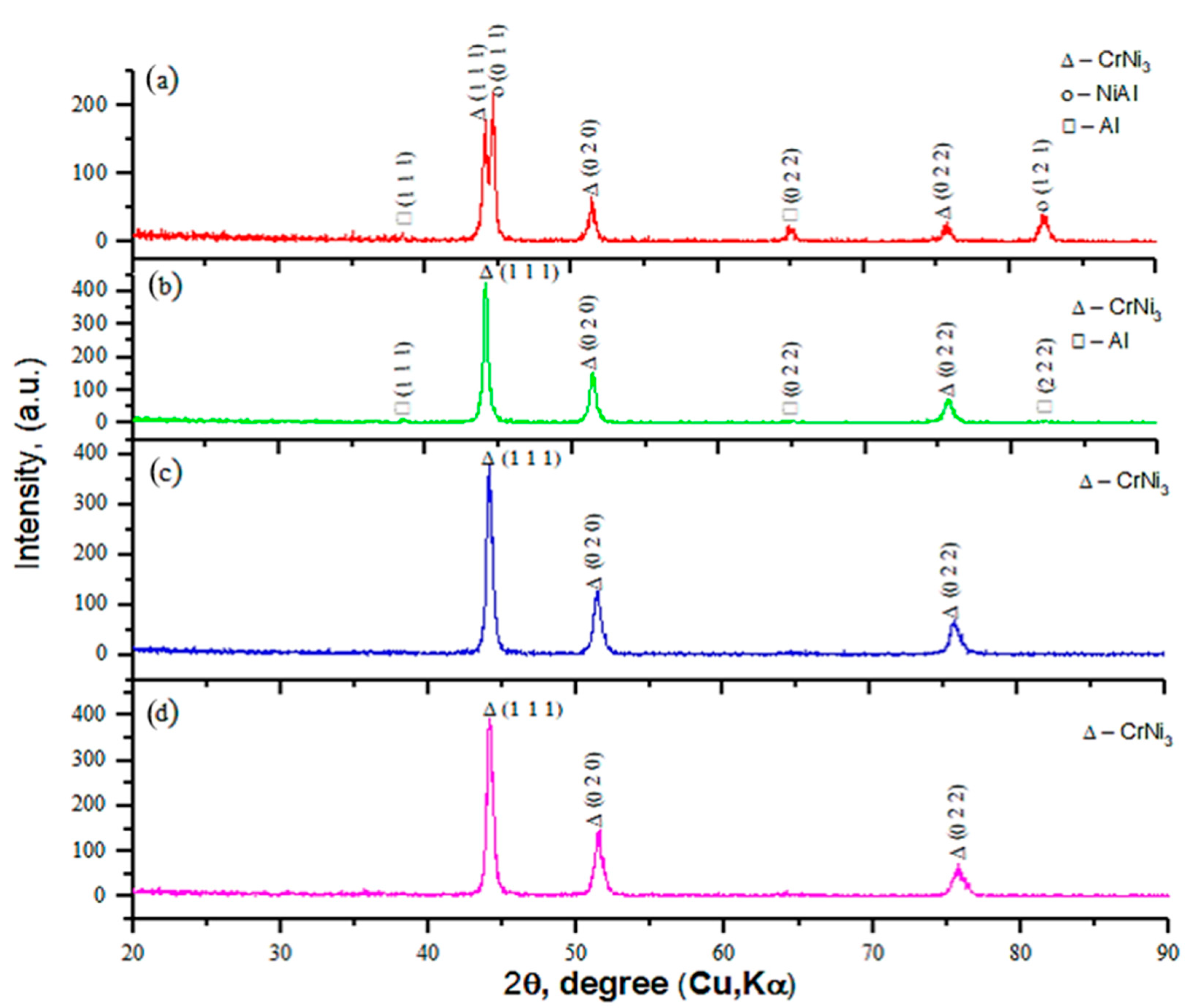
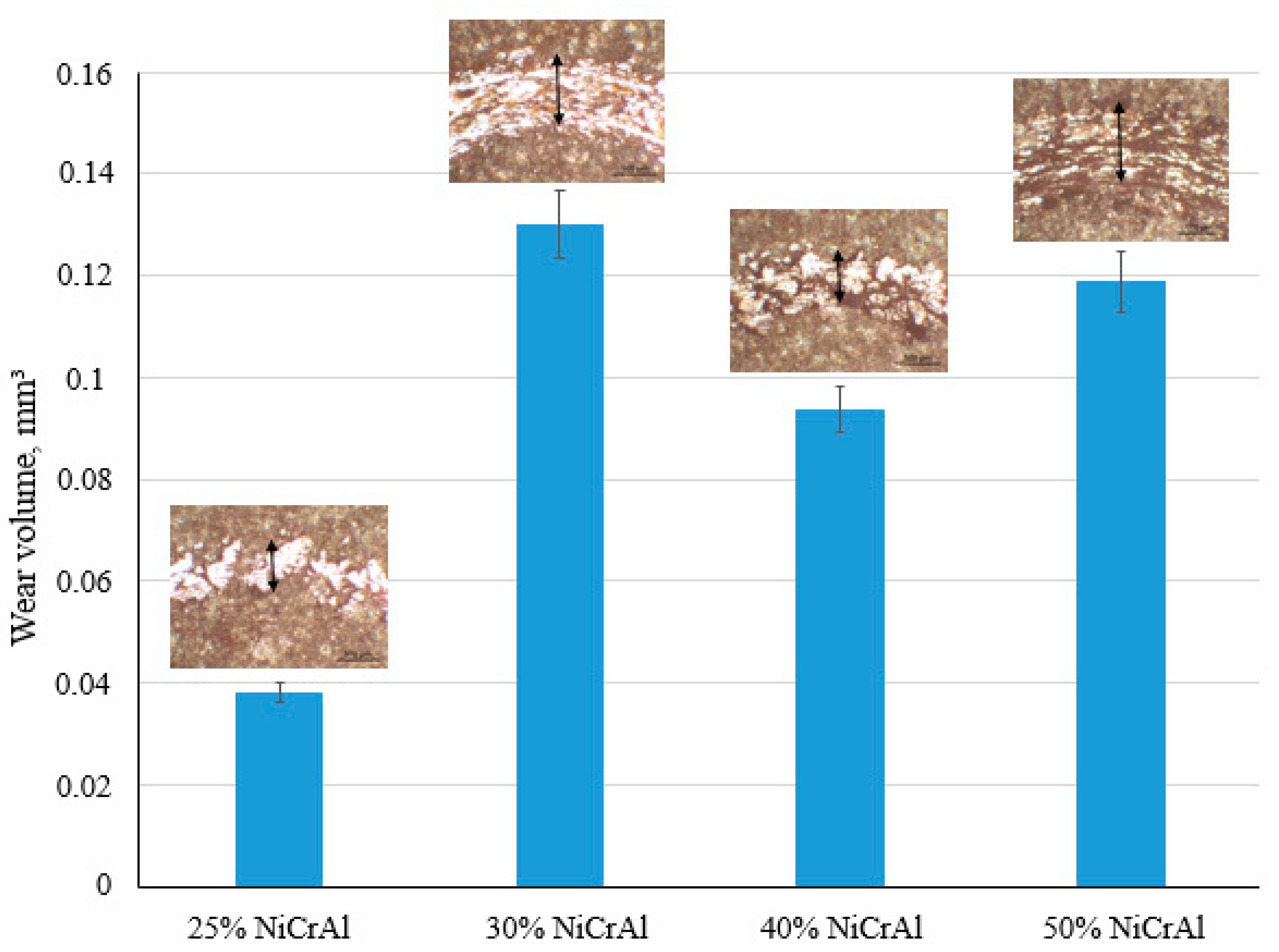
3. Results and Discussions

We obtained Ni–Cr–Al composite coatings by detonation spraying with varying fill volumes (25%, 30%, 40%, 50%). Figure 2 shows surface micrographs and roughness measurements for the coatings. All have surface pores, a typical layered, wave-like arrangement of structural components. We chose parameter Ra, the arithmetic mean deviation of the profile, to be the main parameter characterizing coating roughness. The Ra values of coatings obtained when filling the barrel up to 30%, 40%, 50% were in the range 11.5 to 16.5 µm. The coating obtained when filling the barrel to 25% has a higher roughness value Ra = 20.9 µm. This may be due to a difference in shock wave impact and the resultant compaction of the coating. With a decrease in filling volume, the coating density decreases and thus, the surface roughness increases.
Figure 3 presents the phase composition of the Ni–Cr–Al coatings obtained using the parameters in Table 2. For higher barrel filling degrees (samples No. 3 and 4), only CrNi3 (ICDD/JCPDS № 96-152-5115) phases were observed. This is associated with decreased Al content in the coating and likely is related to the high powder temperature during spraying. When the barrel is filled at the 40–50% level, the temperature in the reaction zone can reach as high as 3500 °C, sufficient to cause the partial or complete evaporation of Al that has a boiling temperature of 2518 °C. In our case, we believe the aluminum powders partially or completely evaporated over the 81 mm distance between the barrel and the substrate.
On the other hand, new phases (Al (ICDD/JCPDS № 96-900-8461) and Ni–Al (ICDD/JCPDS № 96-900-8803)) begin to appear on the X-ray diagram when the level of barrel filling is lower (25–30%). The appearance of the Al phase and the absence of the NiAl phase at a filling volume of 30% is associated with increased temperature in the reaction zone, which does not lead to the formation of the Ni–Al compound. At filling volumes of 40% and 50%, only the NiCr3 phase peaks appear on the diffractogram (Figure 3)
Figure 4 and Figure 5 present tribological test results for the Ni–Cr–Al coatings after ball-on-disc tests. Figure 4 shows volume lost. As can be seen, varying the barrel filling degree leads to various wear resistance. The volume lost is highest for the 30% sample and is in agreement with XRD analysis. This coating was found to contain pure Al, an element that exhibits low wear resistance. By contrast, the 25% sample has the best wear resistance. X-ray diffraction analysis shows this can be caused by the presence of intermetallic Ni–Al phase (see Figure 3a).
Figure 5 graphs the friction coefficients for the coatings. All coatings have coefficients of friction in the range of µ = 0.5–0.7. Coatings produced at 25% and 50% barrel filling showed a relatively low amount of wear. The friction coefficient curves for coatings produced at 25% and 30% barrel filling at the beginning of the test process (before operating time) exhibit jumps. This is likely due to the high roughness values (Ra = 16.5 µm and 20.9 µm) of these coatings.
Based on this study of how deposition mode affects the structure and properties of Ni–Cr–Al coatings, we developed a method for obtaining gradient coatings. This method uses a detonation installation with a single dispenser and a composite powder based on Ni–Cr–Al; technological parameters are varied during the spraying process. We gradually reduced the barrel filling volume from 50% to 25% and then studied the structure and properties of the resulting gradient coating based on Ni–Cr–Al. The choice of deposition mode is based on the experimental results presented above and is intended to produce coatings in which aluminum content increases evenly from the substrate to the coating surface. We take as a starting assumption that intermetalide NiAl, which is formed on the surface at a filling volume of 30%, provides high wear and corrosion and that the NiCr phase formed close to the substrate provides high coating adhesive strength.
Figure 6 presents microhardness distribution on the Ni–Cr–Al gradient coating’s thickness. As can be seen, the dependence is uneven. The microhardness is greatest where the Ni–Al phase is dominant and decreases noticeably where only the Ni–Cr phase is present.
Figure 7 shows the distribution of instrumental nanoindentation and elastic modulus in the thickness of the Ni–Cr–Al gradient coating. As can be observed, nanoindentation values are in the range between 5.1 to 6.2 GPa, whereas elastic modulus values are from 200 to 280 GPa. We note that these results correlate with the microhardness result, for which a maximum is also observed at the same coating depth. Due to the porosity of the coating, however, there is a definite difference in the value of nanohardness and microhardness.
SEM images of Ni–Cr–Al gradient coating cross-sections in Figure 8 show a microstructure characterized by an uneven, highly developed relief layer with a thickness of 350 microns. This layer consisting of elongated particles up to 80 microns in size with a layered structure characteristic of powders subjected to mechanical activation [30,31]
Figure 9 and Table 3 document the results of the EDS analysis carried out at three points. As can be seen, the aluminum content increases from spectrum 001 to spectrum 003. We also found that layers with a high Al content are formed on the surface of Ni–Cr–Al gradient coatings, a finding that is confirmed by the elemental analysis in Table 3, where the mass content of Al in spectrum 003 is 74%.
Figure 10 shows the SEM images and the results of the EDS line analysis. These show that the coating has a gradient structure. Aluminum, which has a dark shade, gradually increases from the substrate to the coating surface. The EDS line analysis was carried out in the direction from the surface to the substrate, as indicated by the arrow in Figure 10a. EDS line analysis (Figure 10b) confirms that aluminum gradually increases from the substrate to the surface of the coating and also shows a high aluminum content on the coating’s outer layer.
The cross-sectional mapping analysis showed (Figure 11) that the coating has a gradient structure. This is especially evident from Al K, which shows the distribution of aluminum over the coating depth. The aluminum concentration gradually increases from the substrate to the coating surface.
Figure 9, Figure 10 and Figure 11 clearly show the gradient structure of the coatings and also that the concentration of aluminum gradually increases from the substrate to the surface. Results of X-ray diffraction analysis (Figure 3) also show phase composition changes when the filling volume is decreased from 50% to 25%: NiCr → NiCr → NiCr, Al → NiCr, Al, NiAl.
Table 4 presents data on the structure and tribological characteristics of the substrate material (steel 12Kh1MF) and the Ni–Cr–Al gradient coating.
Table 4 clearly shows the difference between the mechanical and tribological properties of steel 12Kh1MF and the Ni–Cr–Al gradient coating. It can be argued that the proposed coating adds high physical, mechanical and operational properties to products made of this steel.
Increased hardness and wear resistance are associated with the formation of the NiAl phase. The NiAl intermetallic compound has several features, including low-density, relatively high melting point, excellent resistance to corrosion and oxidation, high strength at elevated temperatures, and relatively low-cost [32,33]. For these reasons, NiAl- based intermetallides are good candidates for a variety of applications, such as the production of blades and other turbine components.

4. Conclusions

Based on this study, we reached the following conclusions:
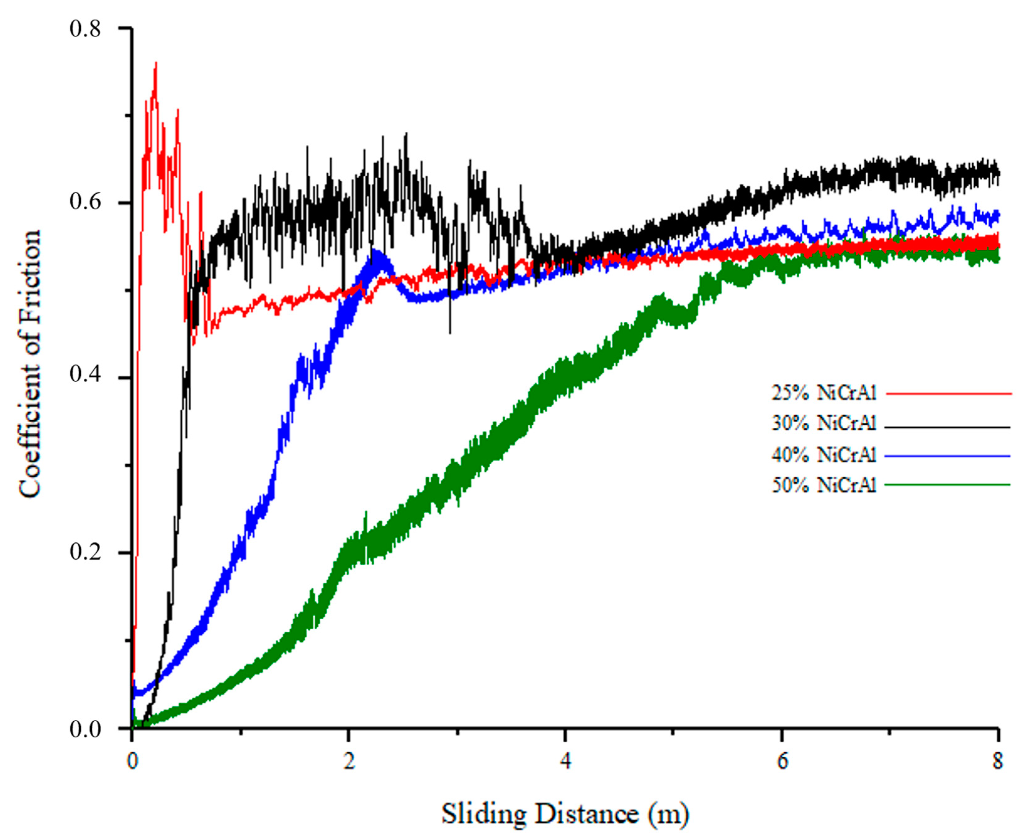
  • The phase composition and properties of detonation coatings strongly depend on the technological spraying parameters. For spraying powder based on Ni–Cr–Al, the chemical and phase composition coatings produced strongly depend on the degree to which the barrel is filled with an O2/C2H2 gas mixture. This provides a way to control the structure and composition of the coatings and, thereby, to obtain coatings with specified properties;
  • A method for producing gradient coatings based on Ni–Cr–Al using a detonation unit with only one dispenser was developed. This method employs a composite powder based on Ni–Cr–Al. Changing the technological spraying parameters provides control over the characteristics of the gradient coatings produced;
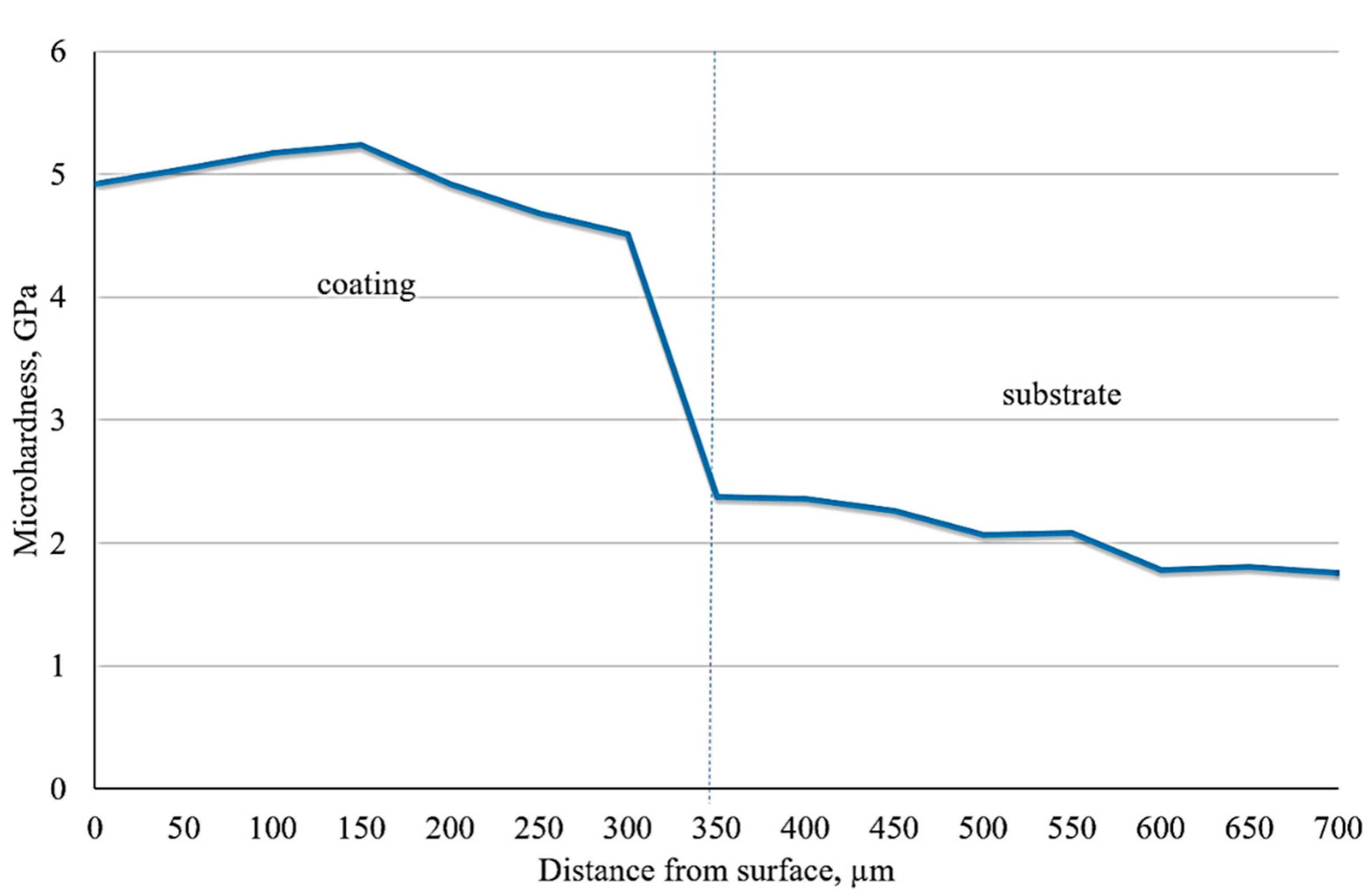
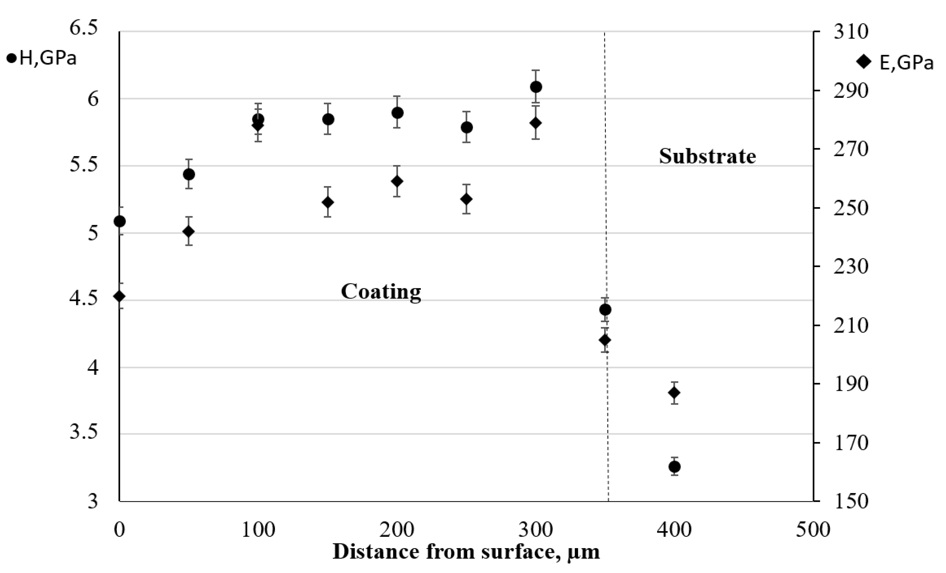
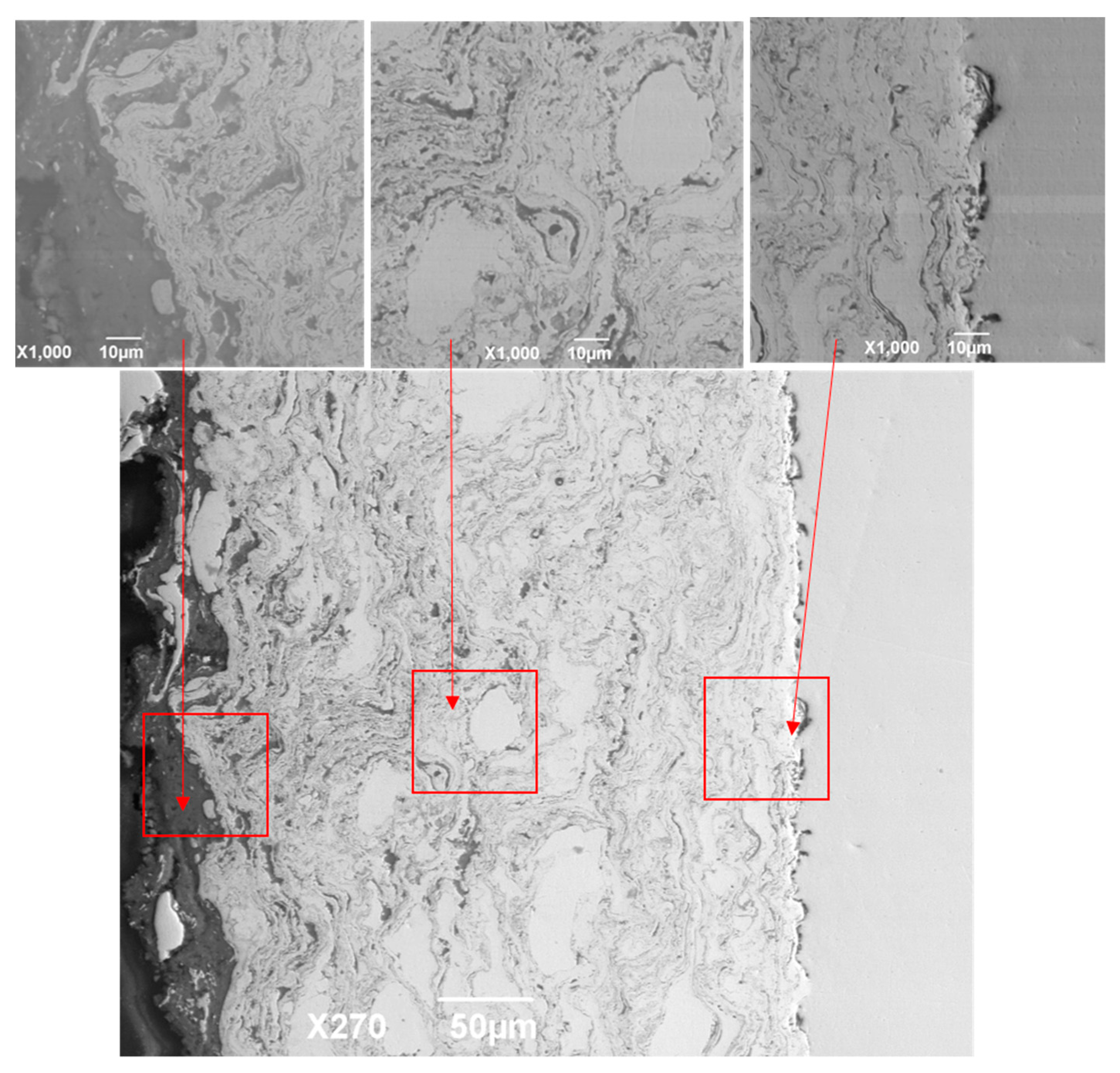
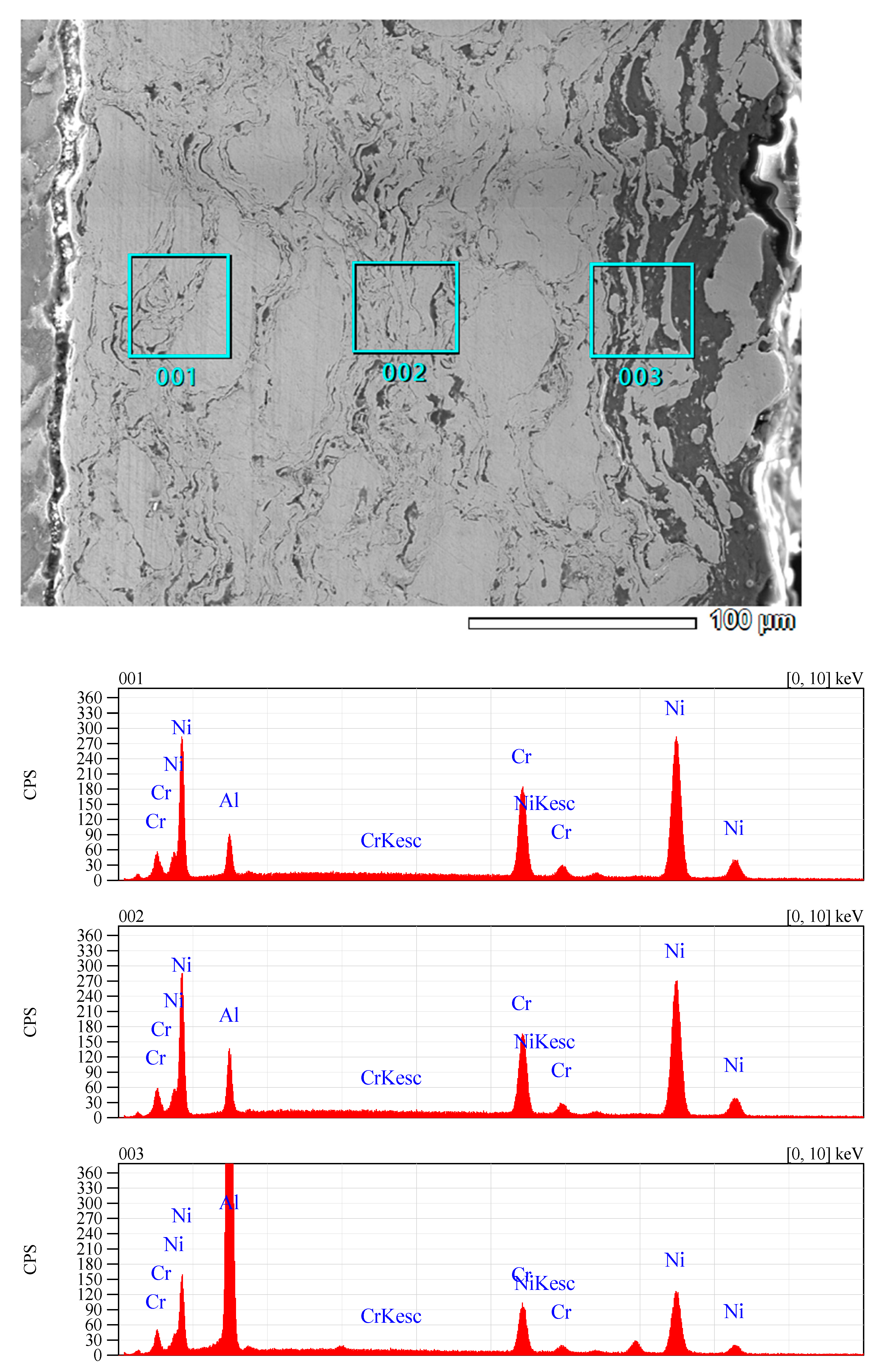
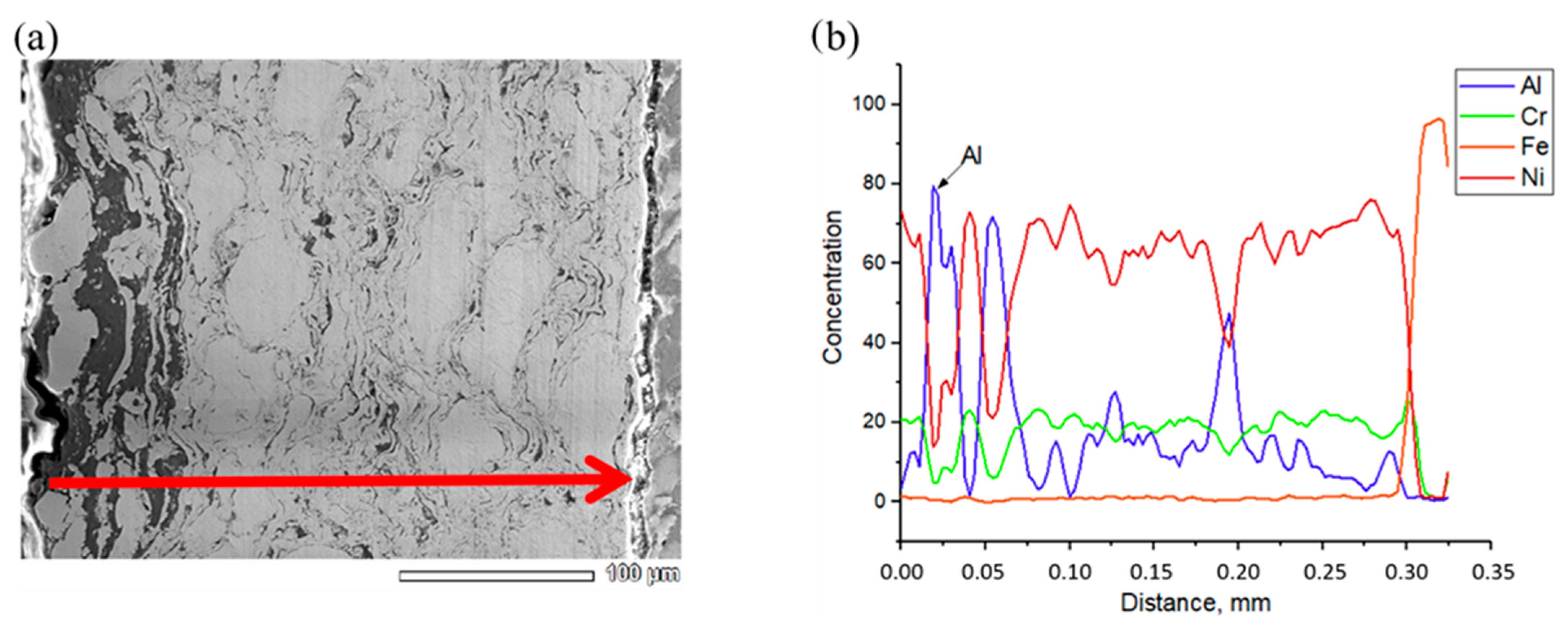
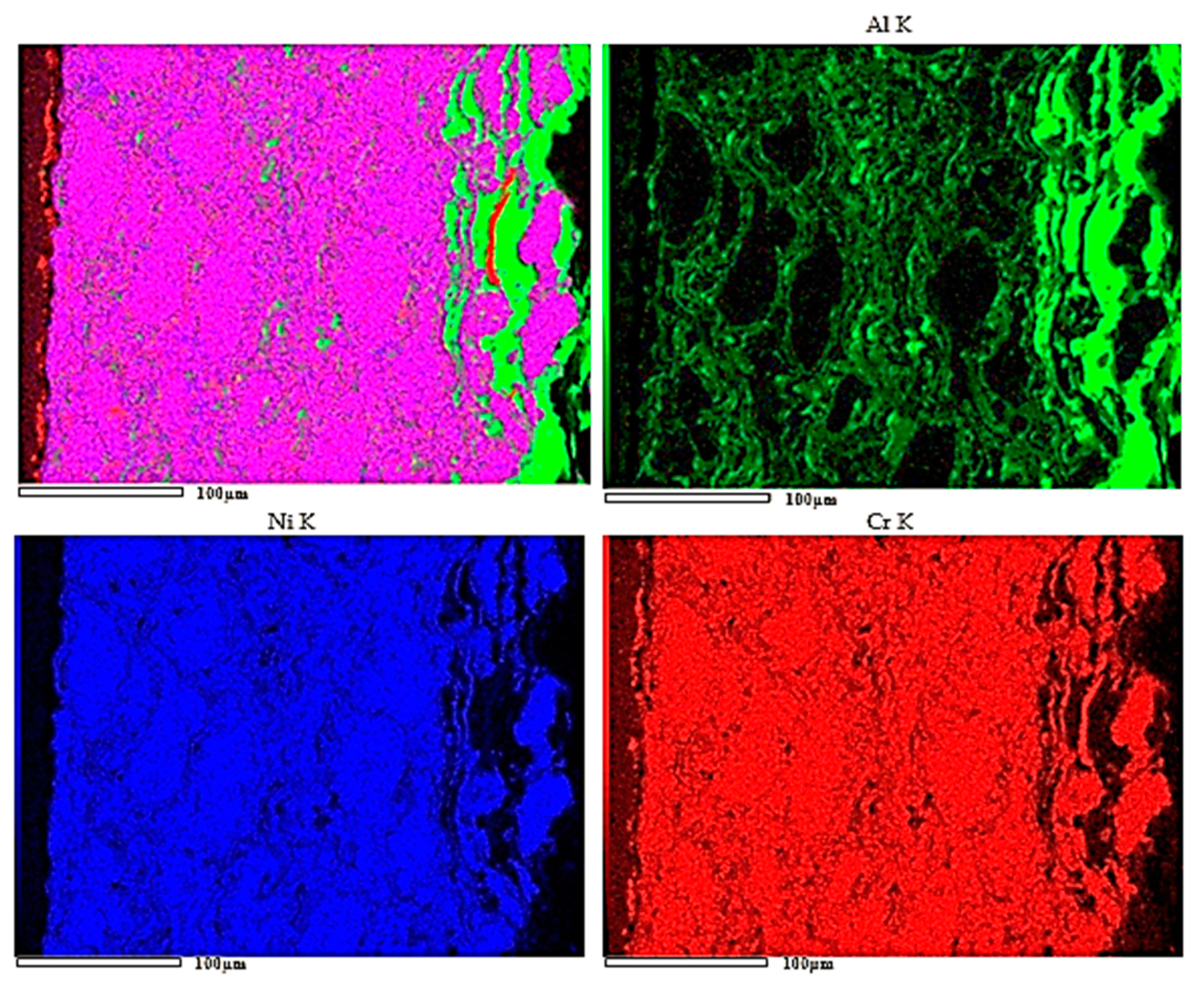
  • A study of the elemental composition by the EDS method showed that the gradient coatings based on Ni–Cr–Al have a gradient structure in which the concentration of aluminum increases gradually from the substrate to the coating surface;
  • Structure analyses results showed that when the barrel filling volume decreases from 50% to 25%, the phase composition of the coating changes as follows: NiCr → NiCr → NiCr, Al → NiCr, Al, NiAl. The Ni–Cr–Al gradient coating thereby obtained presents of phases NiCr with a surface of Al and NiAl that has a high hardness and wear resistance.

Author Contributions

Data curation, R.K.; methodology, M.A.; project administration, M.M.; writing–original draft, B.R. and M.M.; writing–review and editing, Z.S. All authors have read and agreed to the published version of the manuscript.

Funding

This paper was performed within the grant financing of scientific research of the Committee of Science of the Ministry of Education and Science of the Republic of Kazakhstan. Grant AP08957765 and Grant AP09058615.

Institutional Review Board Statement

Not applicable.

Informed Consent Statement

Not applicable.

Data Availability Statement

Data are contained within the article.

Conflicts of Interest

The authors declare no conflict of interest.

References

  1. Nakano, T.; Kousaka, H.; Tanaka, I.; Shibasawa, H.; Kitazume, K.; Hashitomi, H. The friction property of a-C:H:Si deposited by high-speed coating with microwave sheath-voltage combination plasma method. J. Surf. Finish. Soc. Jpn. 2018, 69, 29–33. [Google Scholar] [CrossRef]
  2. Vignesh, S.; Shanmugam, K.; Balasubramanian, V.; Sridha, K. Identifying the optimal HVOF spray parameters to attain minimum porosity and maximum hardness in iron based amorphous metallic coatings. Def. Technol. 2017, 13, 101–110. [Google Scholar] [CrossRef]
  3. Ulianitsky, V.Y.; Batraev, I.S.; Shtertser, A.A.; Dudina, D.V.; Bulina, N.V.; Smurov, I. Detonation spraying behaviour of refractory metals: Case studies for Moand Ta-based powders. Adv. Powder Technol. 2018, 29, 1859–1864. [Google Scholar] [CrossRef]
  4. Niu, S.; Zhou, K.; Xu, L.; Deng, C.; Liu, M.; Mao, J. A comparative study of La0.6Sr0.4Co0.2Fe0.8O3—δ oxygen transport membranes deposited on porous metal supports prepared by supersonic air-gas plasma spraying (SAPS) and low-pressure plasma spraying-physical vapor deposition (PS-PVD). Surf. Coat. Technol. 2016, 307, 963–970. [Google Scholar] [CrossRef]
  5. Student, M.M.; Pokhmurs’ka, H.V.; Zadorozhna, K.R. Structure and wear resistance of VC–FeCr and VC–FeCrCo coatings obtained by supersonic flame spraying. Mater. Sci. 2018, 54, 22–29. [Google Scholar] [CrossRef]
  6. Lu, J.; Zhang, H.; Chen, Y.; Zhao, X.; Guo, F.; Xiao, P. Effect of microstructure of a NiCoCrAlY coating fabricated by high-velocity air fuel on the isothermal oxidation. Corros. Sci. 2019, 159, 108126. [Google Scholar] [CrossRef]
  7. Kuroda, S.; Kawakita, J.; Watanabe, M.; Kim, K.H.; Molak, R.; Katanoda, H. Current statues and future prospects of warm spray technology. In Future Development of Thermal Spray Coatings; Woodhead Publishing: Cambridge, UK, 2015; pp. 163–206. [Google Scholar]
  8. Kilic, M.; Ozkan, D.; Gok, M.S.; Karaoglanli, A.C. Room- and high temperature wear resistance of MCrAlY coatings deposited by detonation gun (D-gun) and supersonic plasma spraying (SSPS) techniques. Coatings 2020, 10, 1107. [Google Scholar] [CrossRef]
  9. Rakhadilov, B.K.; Buitkenov, D.B.; Tuyakbaev, B.T.; Sagdoldina, Z.B.; Kenesbekov, A.B. Structure and properties of detonation coatings based on titanium carbosilicide. Key Eng. Mater. 2019, 821, 301–306. [Google Scholar]
  10. Ulianitsky, V.Y.; Shtertser, A.A.; Batraev, I.S.; Rybin, D.K. Fabrication of layered ceramic-metal composites by detonation spraying. Ceram. Int. 2020, 46, 27903–27908. [Google Scholar] [CrossRef]
  11. Rakhadilov, B.K.; Buitkenov, D.B.; Wieleba, W.; Kylyshkanov, M.K.; Yerbolatuly, D. Impact of the detonation gas spraying mode on the phase composition and adhesional strength of Ti-Si-C coatings. Eurasian Phys. Tech. J. 2020, 17, 59–64. [Google Scholar] [CrossRef]
  12. Rakhadilov, B.K.; Baizhan, D.R.; Sagdoldina, Z.B.; Buitkenov, D.B.; Maulet, M. Phase composition and structure of composite Ti/HA coatings synthesized by detonation spraying. AIP Conf. Proc. 2020, 2297, 020022. Available online: https://aip.scitation.org/doi/abs/10.1063/5.0029754 (accessed on 10 December 2020).
  13. Zhen, H.; Peng, X. Oxidation-resistant CoCrAl coatings fabricated by electrodeposition in combination with electrophoretic deposition. Surf. Coat. Technol. 2018, 352, 541–548. [Google Scholar] [CrossRef]
  14. Shmorgun, V.G.; Bogdanov, A.I.; Taube, A.O.; Gurevich, L.M. Formation of the diffusion barrier at the interface of Cr20Ni80 alloy–Ni-Cr-Al coating. Mat. Sci. Eng 2018, 450, 5–11. [Google Scholar] [CrossRef]
  15. Cheruvu, N.S.; Wei, R.; Shingledecker, J.; Gandy, D.W. Evaluation of nanocrystalline MCrAl coatings for power plants. In Proceedings of the 6th International Conference, Santa Fe, NM, USA, 31 August–3 September 2010. [Google Scholar]
  16. Zhang, P.; Peng, R.L.; Li, X.-H.; Johansson, S. Investigation of element effect on high-temperature oxidation of HVOF NiCoCrAlX coatings. Coatings 2018, 8, 129. [Google Scholar] [CrossRef] [Green Version]
  17. Chadami, F.; Sabour Rough Aghdam, A.; Chadami, S. Microstructural characteristics and oxidation behavior of the modified MCrAlX coatings: A critical review. Vacuum 2021, 185, 109980. [Google Scholar]
  18. Lin, L.; Hu, S.; Hu, Y.; Xu, G.; Jiao, H.; Weng, C. Experimental study on the detonation process of a pulse detonation engine with ionized seeds. Def. Technol. 2020, 16, 178–187. [Google Scholar] [CrossRef]
  19. Latka, L.; Pawlowski, L.; Winnicki, M.; Sokolowski, P.; Malachowska, A.; Kozerski, S. Review of functionally graded thermal sprayed coatings. Appl. Sci. 2020, 10, 5153. [Google Scholar] [CrossRef]
  20. Naebe, M.; Shirvanimoghaddam, K. Functionally graded materials: A review of fabrication and properties. Appl. Mater. Today 2016, 5, 223–245. [Google Scholar] [CrossRef]
  21. Ulianitsky, V.Y.; Dudina, D.V.; Shtertser, A.; Smurov, I. Computer-controlled detonation spraying: Flexible control of the coating chemistry and microstructure. Metals 2019, 12, 1244. [Google Scholar] [CrossRef] [Green Version]
  22. Maulet, M.; Rakhadilov, B.K.; Sagdoldina, Z.B.; Kassymov, A.B.; Kakimzhanov, D.N. Influence of the detonation-spraying mode on the phase composition and properties of Ni-Cr coatings. Eurasian J. Phys. Funct. Mater. 2020, 4, 184–189. [Google Scholar] [CrossRef]
  23. Maulet, M.; Rakhadilov, B.; Stepanova, O.; Sagdoldina, Z.; Kassymov, A.; Kakimzhanov, D. Structure, hardness and wear resistance of the Ni-Cr-Al detonation coating. In Proceedings of the 2020 IEEE 10th International Conference on “Nanomaterials: Applications & Properties” (NAP-2020), Varna, Bulgaria, 28–30 August 2020. [Google Scholar]
  24. GOST 2789-73 Surface roughness. Parameters and Characteristics; Russian GOST: Moscow, Russia, 1975.
  25. GOST 9450-76 Measurements Microhardness by Diamond Instruments Indentation; Russian GOST: Moscow, Russia, 1976.
  26. Oliver, W.C.; Pharr, G.M. An improved technique for determining hardness and elastic modulus using load and displacement sensing indentation experiments. J. Mater. Res. 1992, 7, 1564–1583. [Google Scholar] [CrossRef]
  27. ASTM E2546-07 Standard Pracice for Instrumental Indentation Testing; ASTM International: West Conshohocken, PA, USA, 2007.
  28. ASTM G133-95, Standard Test Method for Linearly Reciprocating Ball-on-Flat Sliding Wear; ASTM International: West Conshohocken, PA, USA, 1995.
  29. ASTM G99-05, Standard Test Method for Wear Testing with a Pin-on-Disk Apparatus; ASTM International: West Conshohocken, PA, USA, 2005.
  30. Sagdoldina, Z.; Rakhadilov, B.; Skakov, M.; Stepanova, O. Structural evolution of ceramic coatings by mechanical alloying. Mater. Test. 2019, 61, 304–308. [Google Scholar] [CrossRef]
  31. Rogachev, A.S.; Shkodich, N.F.; Vadchenko, S.G.; Baras, F.; Kovalev, D.Y.; Rouvimov, S.; Nepapushev, A.A.; Mukasyan, A.S. Influence of the high energy ball milling on structure and reactivity of the Ni + Al powder mixture. J. Alloy. Compd. 2013, 577, 600–605. [Google Scholar] [CrossRef]
  32. Miracle, D.B.; Darolia, R. NiAl and its alloys. Intermet. Compd. 1995, 2, 55–74. [Google Scholar]
  33. Potekaev, A.I.; Chaplygina, A.A.; Chaplygina, P.A.; Starostenkov, M.D.; Kulagina, V.V.; Klopotov, A.A.; Grinkevich, L.S. The influence of grain size on low-stability pre-transitional structural-phase states of NiAl intermetallide. Russ. Phys. J. 2019, 62, 519–526. [Google Scholar] [CrossRef]
Figure 1. Computer-controlled detonation CCDS2000 setup: general view (a) and installation schematic (b).
Coatings 11 00218 g001
Figure 2. Micrographs and roughness of Ni–Cr–Al coatings as a function of barrel fill volume: (a) 25%, (b) 30%, (c) 40%, (d) 50%.
Coatings 11 00218 g002
Figure 3. Diffractograms of Ni–Cr–Al coatings obtained with a barrel filling volume of 25% (a), 30% (b), 40% (c) and 50% (d).
Coatings 11 00218 g003
Figure 4. Results of tribological testing of Ni–Cr–Al coatings according to the scheme “ball-disk”.
Coatings 11 00218 g004
Figure 5. Friction coefficients for the Ni–Cr–Al coatings.
Coatings 11 00218 g005
Figure 6. Ni–Cr–Al gradient coating’s microhardness distribution on its thickness.
Coatings 11 00218 g006
Figure 7. Distribution of hardness (H) and elastic modulus (E) over the depth of the Ni–Cr–Al gradient coating.
Coatings 11 00218 g007
Figure 8. SEM image of the cross-section of Ni–Cr–Al gradient coating.
Coatings 11 00218 g008
Figure 9. EDS analysis of the Ni–Cr–Al gradient coating in cross-section.
Coatings 11 00218 g009
Figure 10. SEM cross-section images (a) and element distribution (b) as a function of depth in the Ni–Cr–Al gradient coating.
Coatings 11 00218 g010
Figure 11. Maps of element distribution in the Ni–Cr–Al gradient coating.
Coatings 11 00218 g011
Table 1. Chemical composition of 12Kh1MF steel.
CSiMnNiSPCrMoVCu
0.1–0.150.17–0.370.4–0.7to 0.3to 0.025to 0.030.9–1.20.25–0.350.15–0.3to 0.2
Table 2. Technological parameters for obtaining Ni–Cr–Al coatings.
O2/C2H2 Barrel Filling Volume,%Spray Distance, mmNumber of Shots
118562525040
218563025040
318564025040
418565025040
5185625–5025040
Table 3. Elemental composition of the Ni–Cr–Al gradient coating based on SEM analysis.
ElementAl, Mass%Cr, Mass%Ni, Mass%Total, Mass%
Spectrum 00110.8821.8267.30100.00
Spectrum 00216.2819.2364.49100.00
Spectrum 00374.097.5418.37100.00
Table 4. Experimental data on the structure and tribological characteristics of the functional gradient coating Ni–Cr–Al.
Name.Phase CompositionMicro
Hardness, GPa
Nano
Hardness, GPa
Young′s Modulus, GPaFriction CoefficientWear Volume, mm3
Substrateα-Fe1.80–2.503.0–3.50170–1900.4–0.450.08
Ni–Cr–AlNiCr, Al, NiAl4.50–5.235.10–6.20200–2800.5–0.60.0378
Publisher’s Note: MDPI stays neutral with regard to jurisdictional claims in published maps and institutional affiliations.

