Abstract
The paper considers the research results of structural-phase state and tribological characteristics of detonation coatings based on Ti–Si–C, obtained at different filling volumes of the explosive gas mixture barrel of a detonation gun. The results analysis indicates that the phase composition and properties of detonation coatings strongly depend on the technological parameters of spraying. With an increase of the explosive mixture in the filling volume of the detonation barrel up to 70% of the coatings consist mainly of the TiC phase, because high temperature leads to a strong decomposition of Ti3SiC2 powders. Thus, the XRD results confirm that at 70% of the explosive gas mixture’s filling volume, partial decomposition and disintegration of the powders occurs after detonation spraying. We established that detonation coatings based on titanium carbosilicide obtained at the explosive gas mixture’s filling volume at 60% are characterized by high wear resistance and adhesive strength. Thermal annealing was performed after spraying in the temperature range of 700–900 °C for 1 h to reduce microstructural defects and improve the Ti–Si–C coating characteristics. As a result of the heat treatment in the Ti–Si–C system at 800 °C, we observed that an increase in the volume fraction of the Ti3SiC2 and TiO2 phases led to a 2-fold increase in microhardness. This means that the after-heat-treatment can provide a sufficient reaction time for the incomplete reaction of the Ti–Si–C (TSC) coating during the detonation gun spraying. Thus, annealing can provide an equal distribution of elements in the coatings.
1. Introduction
Currently, carbides, silicides, and transition metals have aroused considerable interest due to increasing demand. In particular, the most frequently mentioned phases in the Ti–Si–C system are TiC, Ti5Si3, and Ti3SiC2. They attract considerable interest due to their unique metallic combination and ceramic properties. As metals, they have good electrical and thermal conductivity, high plasticity, good machinability and excellent thermal shock resistance. As ceramics, they have low density, high stiffness, high melting points, and good resistance to oxidation and corrosion [1,2,3]. Such exceptional properties result from the coexistence of strong covalent ionic MX bonds and weak metallic MA bonds within a layered hexagonal structure (space group P63/mmc) of MAX materials, which are created by repeating a three-layer structure (consisting of two Mn + 1xN layers intercalated by a single atomic layer A) [4]. A unique distinctive feature of these materials is the layered structure of their crystal lattice—the regular arrangement of layers of M and A atoms of elements that have reduced binding energy between them. Tightly packed layers of titanium atoms alternate with layers of silicon atoms, and carbon atoms occupy octahedral interstices between titanium atoms [5,6]. These properties make the phase material Ti3SiC2 MAX ideal for extreme condition applications. In addition, system Ti–Si–C has good characteristics under conditions of abrasive wear and corrosion. However, production coatings based on Ti–Si–C production by traditional methods are associated with a high temperature and duration of their obtaining process. Sprayed coatings based on Ti3SiC2 are usually accompanied by phases TiC and Ti–Si. The short reaction time of powder mixtures and the decomposition of Ti–Si–C at high temperature are the main problems for the phase’s purity. An analogous problem occurs with plasma spraying of coatings [7]. In addition, using heat treatment to improve the characteristics of the resulting coatings is not well studied. Considering their tribological application, the question of how to deposit Ti3SiC2-based coatings with high wear resistance is still undecided.
Among the coating methods, detonation spraying and high-velocity oxy-fuel (HVOF) spraying [8,9,10,11] have an obvious advantage in comparison to plasma spraying and other spraying methods because of high particle flight speed and lower operating temperature. Detonation spraying coatings from powder are based on the use of explosion energy of a fuel–oxygen mixture and are known as a promising method for obtaining coatings from various materials with good adhesion [12]. The higher velocity flow of particles allows providing higher density and adhesive strength of the detonation coating. The essential advantage of the detonation spraying method is the ability to accurately control the amount of explosive gas mixture used for each shot of the detonation gun, which allows changing the degree of thermal and chemical effects of detonation products on the particles of spraying powder [13]. Depending on the composition of the acetylene–oxygen explosive mixture, from a O2/C2H2 ratio and from the nature of the gas carrier, chemical interactions may occur between the individual phases of the composite particles [14,15]. In this regard, the detonation method of coating is of considerable interest. Therefore, much attention is directed at obtaining detonation coatings from binary and ternary phases relevant to the Ti–Si–C system.
In connection with the above, the aim of this work is to study the structural features and tribological properties of coatings based on Ti–Si–C, which are obtained by the detonation method under various deposition modes, as well as to study the effect of thermal annealing on the structural and phase states of coatings based on Ti–Si–C.
2. Materials and Methods
By detonation spraying on the surface of steel U9 (with 0.94 wt.% C) Ti3SiC2 coatings were obtained. The chemical composition of the powder was Ti: 74 wt.%; SiC: 20 wt.%; C: 6.0 wt.%, and powder particle size was between 20 and 40 µm. Before spraying, the substrate was sandblasted to improve the adhesive strength of the coatings. The value of the surface roughness parameter after sandblasting was on average (Ra) 3.2 microns. The distance between the treated surface of the sample and the detonation barrel was 200 mm. The straight barrel diameter was 20 mm.
The CCDS2000 (LIH SB RAS, Novosibirsk, Russia) detonation set-up was used to obtain the coatings, which has a system of electromagnetic gas valves that regulate the supply of fuel and oxygen and control the system purging (Figure 1). The acetylene–oxygen mixture was used as a fuel gas, which is the most used fuel during detonation spraying of powder materials. Spraying was carried out at the ratio of the acetylene–oxygen mixture O2/C2H2 = 1.856. The volume of the explosive gas mixture of the detonation gun barrel was varied from 50% to 70%. The average shot frequency of working gases at 4 Hz was: acetylene 4–7; propane–butane mixture 2…3, 5; oxygen 10…12; nitrogen 10…15 m3/h. Nitrogen was used as a carrier gas.
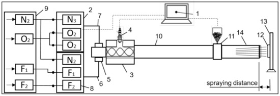
Figure 1.
Schematic diagram of the CCDS2000 detonation complex: 1—control computer; 2—gas distributor; 3—mixing-ignition chamber; 4—spark plug; 5—barrel valve; 6—fuel line; 7—oxygen line; 8—gas valves; 9—gas supply unit; 10—indicated part of the barrel; 11—powder feeder; 12—workpiece; 13—manipulator; 14—the muzzle of the barrel; F1—acetylene; F2—propane–butane; O2—oxygen; N2—nitrogen.
The research phase composition of the samples was studied by X-ray diffractometer X’PertPro (Philips Corporation, The Nederlands) using CuKα radiation. The shooting was carried out in the following modes: tube voltage U = 40 kV; tube current I = 20 mA; exposure time 1s; shooting step Δ2θ ~ 0.02° and 2θ = 10–90°. The surface morphology was studied by scanning electron microscopy using secondary (SEs) and backscattered electrons (BSEs) on a Vega3 (Tescan, Brno, Czech Republic) scanning electron microscope. Tribological tests for sliding friction were performed on a high-temperature tribometer TRB3 (Anton Paar Srl, Peseux, Switzerland) using the standard “ball-disc” technique (international standards ASTM G 133-95 and ASTM G 99) [16,17]. A counterbody was used comprising a ball with a diameter of 3.0 mm made of SiC-coated steel. The tests were carried out at a load of 10 N and a linear velocity of 3 cm/s, a radius of wear curvature of 4 mm, the friction path was 41 m. Wear tracks were studied using a non-contact 3D profilometer MICROMEASURE 3D (STIL, France) station. The CSEM Micro Scratch Tester (Neuchatel, Switzerland) was used to study the adhesive characteristics of coatings by the “scratching” method. Scratch testing was performed at a maximum load of 30 N; the rate of change of normal loading on the sample was 29.99 N/min, the speed of movement of the indenter was 9.63 mm/min, the length of the scratch was 10 mm, the radius of tip curvature was 100 microns. To obtain reliable results, three scratches were applied to the surface of each coated sample. The obtained coatings with mechanical properties (Young’s modulus, hardness) were studied by a NanoScan-4D Compact (FSBI TISNCM, Russia) nanohardometer. The tests were carried out at a load of 200 mN. Loading time, unloading time, and the time of supporting the maximum load were each 5 s. The dependence of the penetration depth on the applied force at the loading and unloading stages was determined by the Oliver–Pharr method. At least 10 measurements were carried out on each sample, the results of which were averaged. Sample tests for abrasive wear were carried out on an experimental stand (Figure 2a) against soft fixed abrasive particles according to the “rotating roller–flat surface” scheme in accordance with GOST 23.208-79, which conforms to the American standard ASTM C 6568 [18,19]. Sample tests for impact and abrasive wear were carried out on an experimental stand in accordance with GOST 23.207-79 (Figure 2b) [20]. For a comparative assessment of the wear resistance of detonation coatings, tests were carried out in the following modes: impact energy E = 3.3 J, impact velocity υ = 1 m/s, and impact frequency n = 200 min−1. The samples tested for abrasive and impact-abrasive wear underwent 8–10 tests. After each test, the mass loss of the samples was determined and was given the average value with the standard deviation. The microhardness of the samples was measured by a diamond indenter on a PMT-3M (LOMO, Russia) device in accordance with GOST 9450-76 [21], at a load of 200 g and an exposure time of 10 s [22]. Thermal annealing of coated samples was carried out in a laboratory tubular electric furnace of resistance SUOL-0.4.4/12 (0.4.4—dimensions of working space, 40 × 400 mm; 12—the nominal temperature of the working space, 1200 °C) in a vacuum of 10−2 Pa at temperatures of 700 °C, 800 °C, and 900 °C for 1 h, followed by cooling in the furnace. The temperature was measured and regulated by a precision high-precision temperature controller HTC-2 [23].
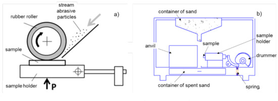
Figure 2.
The experimental test stand for testing of samples: (a) abrasive wear according to the “rotating roller–flat surface” scheme; (b) impact and abrasive wear.
3. Results and Discussions
Figure 3 shows the diffractograms of Ti3SiC2 powder and Ti–Si–C coating obtained at the barrel filling volume of an explosive gas mixture from 50% to 70%. The results of powder XRD analysis showed that the powder consisted of Ti3SiC2 as the main phase and TiC as the secondary phase. The diffractograms of Ti–Si–C coatings showed a decrease in the intensity of Ti3SiC2 diffraction lines and an increase in TiC intensity, which indicated a partial decomposition of the Ti–Si–C system and agreed with the data [24,25,26,27,28,29,30,31]. A decrease in the intensity of diffraction lines in the Ti–Si–C system after detonation spraying was due to the deintercalation of silicon from Ti–Si–C lattice layers [25,26] since the silicon flatness had weak connections with Ti–C flatness. This occurred due to detonation spraying when the Ti–Si–C system lost a certain amount of silicon due to its high “fugacity” [27]. XRD analysis showed that when the barrel was filled with explosive mixtures to 50% and 60%, a low degree of Ti3SiC2 decomposition was achieved, and also after spraying the appearance of reflexes (100) and (106) of the Ti3SiC2 phase was detected. With an increase in the filling volume of the detonation barrel to 70%, a decrease in the intensity of the diffraction peaks of Ti3SiC2 was observed because of the decomposition of the powder into TiC. In the detonation wave flow, the Ti3SiC2 powder decomposed due to high-speed shock interaction heated to high temperatures. Thus, the XRD results confirmed that at 70% of the explosive mixture’s filling volume, partial decomposition and disintegration of the powders occurred after detonation spraying.
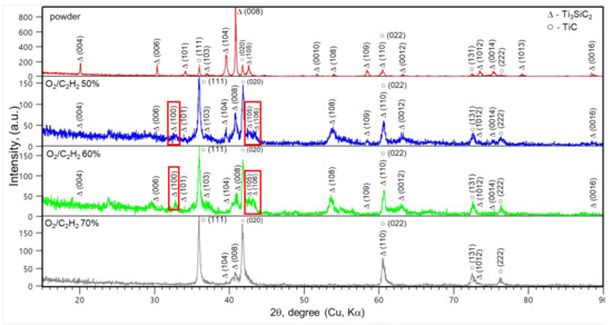
Figure 3.
Diffractogram of Ti3SiC2 powder and Ti–Si–C coatings obtained at different filling volumes of the explosive gas mixture of the detonation gun barrel.
The SEM image shows that the cross section of the sprayed coating is not flat and continuous. From the image’s analysis, it follows that the coating structure has an inhomogeneous structure with pores, a typical layered, wave-like arrangement of structural components. Significant pores (the dark area highlighted by a circle) can be seen in the image of the coating cross section (Figure 4b,d). The border between the coating and the base has a characteristic zigzag shape. The structure consists of small particles and several large flat spots with periodic observations of the morphology of terraces in certain areas (Figure 4a,c), the light gray area indicates mainly the Ti3SiC2 phase, highlighted by a rectangle, and the friable and dark gray area indicates the TiC phase. Dark areas have large volume fractions in the coatings. The surface roughness of coatings Ti–Si–C (Ra) comprises 2.5–2.65 µm.
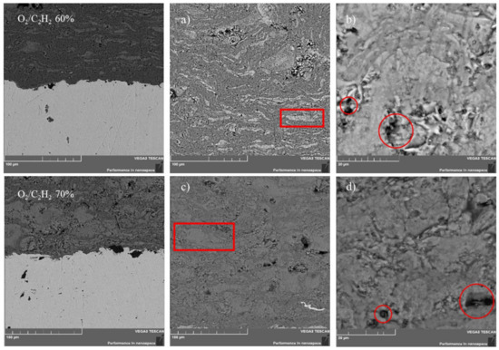
Figure 4.
SEM images of the morphology of coating cross section: (a) Ti–Si–C 60% while 100 μm; (b) Ti–Si–C 60% while 20 μm; (c) Ti–Si–C 70% while 100 μm; (d) Ti–Si–C 70% while 20 μm.
One of the main factors determining the coating quality was adhesion. Figure 5 shows the adhesive strength testing results of scratch testing. The moment of coating adhesive or cohesive failure was fixed visually after testing using an optical microscope with a digital camera, also by changing two parameters: acoustic emission and friction force. It should be noted that not all recorded events associated with the destruction of the coating describe the actual adhesion of the coating to the substrate. Various registration parameters during testing processes allowed fixing different coating failure stages; so, Lc1 means the moment of appearance of the first crack, Lc2 the peeling of coating areas, and Lc3 the plastic abrasion of the coating to the substrate [32]. According to the type of change in the acoustic emission (AE) amplitude, it was possible to judge the crack formation intensities and their development in the sample during scratching. The Ti–Si–C system coatings that occurred during the explosive gas mixture filling volumes of 50% and 60% were visible, the first crack was formed at a load of Lc1 = 12 N. Then the process continued in a certain cycle. A corresponding peak of acoustic emission accompanied each crack formation (Figure 5a,b). Partial abrasion of the coating to the substrate was judged by a sharp change in the friction force growth intensity. This occurred at a load of Lc3 = 29 N, which was also confirmed by visual observation, noting a change in the color of the sample material at the bottom of the scratch (Figure 5a,b). The Lc3 value indicated a high adhesive strength of coating adhesion to the substrate.
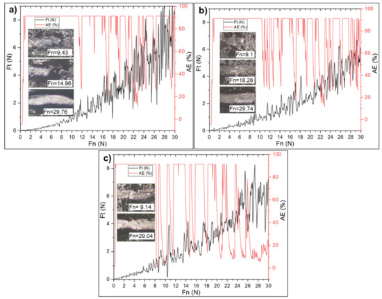
Figure 5.
Results of the scratch test of Ti–Si–C coatings obtained at different filling volumes of the explosive gas mixture of the detonation gun barrel: (a) 50%, (b) 60%, and (c) 70%.
The Ti–Si–C system coating obtained at the explosive gas mixture filling volume of 70% shows appearance cracks (Figure 4c) observed at Lc1 = 8 N load. According to adhesion tests, it can be argued that the cohesive destruction of the sample coating occurred at 8 N, and its adhesive destruction at 29 N. The Ti–C system has a higher stiffness, so it is natural to expect minimal elastic and intense plastic deformation during the adhesion test [33].
For coatings of this functional purpose, wear resistance is one of the most important exploitation properties, which is reflected both in the capacity of structures as a whole and in the conservation of the geometric dimensions of individual parts. The results of coating tribological tests showed that the filling volume of the explosive mixture and the coating structures had a significant impact on the value of the friction coefficient of the coating surface and wear resistance. Therefore, in the case of composite coatings Ti–Si–C obtained with the filling volumes of the explosive mixture at 50% and 60% in the detonation gun barrel, the friction coefficient at the initial stage of testing to 18.40 and 25.10, respectively, was 0.15–0.20 µ and slightly increased; subsequently the friction coefficient increased monotonously from 0.25 to 0.60 µ (Figure 6). The obtained coating Ti–Si–C system’s friction coefficient at a filling volume of 70% was 0.60 µ. According to the XRD analysis results, the increasing wear resistance of the Ti–Si–C system coatings with detonation barrel filling volumes of 50% and 60% was related to a larger proportion of the Ti3SiC2 phase.
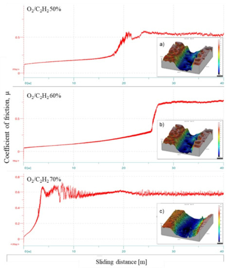
Figure 6.
Tribological tests results of Ti–Si–C coatings obtained at different filling volumes of the explosive gas mixture of the detonation gun barrel and track profiles: (a) 50%; (b) 60%; (c) 70%
With the profilometer were taken images of the wear track of the studied samples (Figure 6). Assessing the samples’ wear resistance based on the wear tracks’ geometric parameters illustrated that the depth of the sample track at 70% of the explosive mixture’s filling volume was significantly greater when compared with others. The detonation coatings based on titanium carbolized were characterized by high wear resistance.
The study results of the mechanical characteristics of the obtained coatings were carried out by the Oliver–Pharr method, and typical dynamic loading–unloading diagrams are shown in Figure 7. From the analysis of the loading and unloading curves, it can be seen that the penetration depth of the nano-indenter in the cases of explosive gas mixture filling volumes of 50% and 60% was less than in the case of 70% filling volume. According to the analysis of the indentation curves, it can be concluded that the elastic stiffness of the coatings during 70% filling was higher (Figure 7b) when compared to the rest (Figure 7a,b). According to the XRD analysis results, when the filling volume of the explosive mixture in the detonation gun barrel increased to 70% a coating was formed with a high content of the TiC phase. Thus, the results of nano-indentation and scratch testing were in good agreement and confirmed the formation of TiC, which had a higher stiffness compared to Ti3SiC2.

Figure 7.
Loading–unloading curves for Ti–Si–C coatings obtained at a different explosive gas mixture filling volumes of the detonation gun barrel: (a) 50%; (b) 60%; (c) 70%.
The values of hardness and modulus of elasticity of the research samples obtained from the loading–unloading curve analysis are shown in Table 1. As visible from Table 1, coatings with a high content of Ti3SiC2 had higher hardness values compared to the coating with the prevailing TiC phase.

Table 1.
Results of nano-indentation.
The detonation spraying process is characterized by a significant number of technological parameters. The complexity and insufficient study of the phenomena underlying it makes it very difficult to trace the relationship of individual parameters to determine the process optimal modes, using one-factor experiments. Therefore, experimental and statistical methods of regressive analysis and the theory of experiment planning are used when optimizing the process. Abrasive and impact-abrasive wear are two of the main factors that limit working parts, machines, and equipment components for various purposes. To assess the resistance of Ti–Si–C coatings to abrasion and impact-abrasive wear, tests were carried out on special stands. Table 2 shows the test results of the abrasive and impact-abrasive wear. The coated samples’ mass loss was less than that of the original sample, which indicates an increased resistance to impact and abrasive wear. This is due to the presence of a larger proportion of the hardening carbide phase TiC in the Ti3SiC2 coating. This is due to an increase of the strengthening phase TiC in the composition of the protective coating. There is a significant increase in internal stresses and a decrease in the amount of the more plastic phase, which ultimately decreases toughness.

Table 2.
Abrasive and impact-abrasive wear test results.
According to the determination results of the samples’ mass loss after testing wear on the fixed abrasive (Figure 2), the greatest strength was found in a coating obtained by the 60% (0.0122 g) filling volume of the detonation gun barrel and the smallest was in the filling volume of 70% (0.0203 g), the wear resistance of all coatings was higher than the initial sample (0.0265 g). The detonation coatings based on titanium carbolized were characterized by high wear resistance.
Thus, in this work, we made the effort to obtain composite coatings based on Ti–Si–C with the Ti3SiC2 phase by detonation spraying. The analysis of the obtained experimental results indicated that the phase composition and properties of detonation coatings strongly depend on the technological parameters of spraying. With an increase of explosive gas mixture in the filling volume of the detonation barrel up to 70% of the coatings consisted mainly of TiC phases, since high temperature leads to a strong decomposition of Ti3SiC2 powders [34]. Consequently, the successful production of high-purity MAX-phase coatings by detonation spraying was not reported. Based on the analysis of literature sources [35,36] and preliminary studies, it was suggested that if gas–thermal deposition of substances of the Ti–Si–C system is carried out, it would be possible to obtain a multiphase coating containing such phases as carbides, silicides, and carbosilicides of titanium, and during subsequent heat treatment–regulation of its phase composition. Thermal annealing was performed in the temperature range 700–900 °C for 1 h.
The Vickers hardness of Ti–Si–C composite coatings before and after annealing is shown in Figure 8. The hardness of the composite coating increased significantly with increasing the annealing temperature: at T = 700 °C, the microhardness was 1150 HV; at T = 800 °C, the microhardness was 1400 HV; and at T = 900 °C, the microhardness decreased to 850 HV.
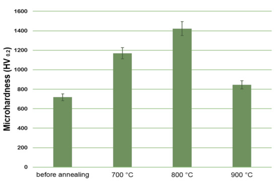
Figure 8.
Effect of annealing temperature on the microhardness of coatings based on Ti–Si–C.
Aiming to identify the cause of the change in microhardness, we performed XRD analysis of coatings before and after annealing. The results of XRD analysis of coatings showed (Figure 9) that the coating before annealing consisted of TiC and Ti3SiC2 phases.
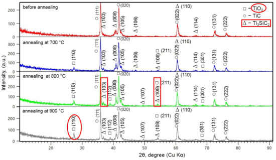
Figure 9.
Diffractograms of Ti–Si–C coatings at different annealing temperatures.
After annealing, the formation of TiO2 phases and an increase in the reflex intensities (103) and (108) of Ti3SiC2 phases were observed. Compared to the after-sprayed coatings, the phase fraction of the Ti3SiC2 phase in the after-annealing coatings increased significantly. A change in the fraction of phases indicated a solid-phase transformation during thermal activation. An increase in the TiO2 line intensity was observed after annealing at T = 900 °C, which indicated an increase in the thickness of the oxide layer. The increase in microhardness after annealing was associated with an increase in the content of Ti3SiC2 phases in coatings. At the same time, after annealing at T = 900 °C, the decrease in microhardness was insignificant due to an increase in the oxide layer’s thickness. After annealing at 800 °C, an increase in the Ti3SiC2 line intensity indicated an increase in the symmetric movements of C atoms in the Ti3SiC2 molecule. This means that subsequent heat treatment provided sufficient reaction time for an incomplete reaction of the Ti–Si–C (TSC) coating during detonation spraying.
The microstructure of Ti–Si–C800 consisted of a titanium-rich region (light region) and a TiCx region diluted by Si (light gray regions). Heat treatment can lead to the diffusion of C and Si atoms [37]. Thus, annealing can provide a more homogeneous distribution of atoms in coatings after annealing. This can be verified by displaying the Ti–Si–C and Ti–Si–C800 elements in Figure 10. As shown in Figure 10, the Ti, C, and Si maps show separate rich and scarce areas. Moreover, the C and Si atoms have a similar distribution in most regions of the element map. The red color on the Ti map corresponds to the dark zones of C deficiency and Si deficiency on the C and Si maps, respectively, identified as the Ti phase (C, Si). After annealing at 800 °C, the three elements showed a more homogeneous distribution (Figure 11). This means that the high temperature provided a more intense diffusion of C and Si atoms.
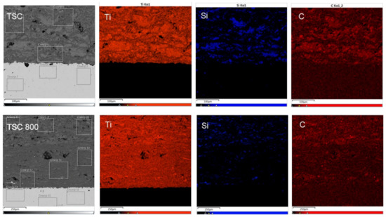
Figure 10.
The microstructure of the cross section of coatings with a color images of energy-dispersive spectrometer (EDS) mapping and the result of analysis after annealing at 800 °C.
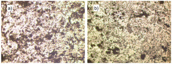
Figure 11.
The coatings’ surface morphology before (a) and after (b) annealing at 800 °C.
The results of tribological testing of coatings showed that the temperature of thermal annealing and the structure of the coatings themselves had a significant impact on the coefficient of friction of the coating surface and wear resistance. So, in the case of composite Ti–Si–C coatings, the friction coefficient was 0.65–0.70 before annealing. After thermal exposure at temperatures up to 800 °C, the friction coefficient at the initial stage of testing (up to 12.40 m) was 0.30–0.35 and a slight increase occurred, at which the friction coefficient increased monotonically from 0.35 to 0.70 as in the case before annealing (Figure 12). According to the results of the X-ray phase analysis, an increase in the wear resistance of the surface layers of the Ti–Si–C composite material after 800 °C was associated with the formation of TiO2 and the presence of a larger fraction of the TiC carbide hardening phase (Figure 9). In [38,39], it was shown that an oxide compound based on TiO2 increases the wear resistance and strength of materials. Detonation coatings based on titanium carbosilicide are characterized by high wear resistance.
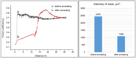
Figure 12.
Results of tribological experiments of Ti–Si–C coatings before and after annealing at 800 °C.
4. Conclusions
The paper described an experimental study of the effect of the detonation gas filling mode on the phase composition and strength characteristics of the Ti–Si–C coatings system. It was shown that the phase composition of detonation coatings can be significantly changed relative to the phase composition of the initial powders, depending on the filling volume of the detonation barrel with an explosive acetylene–oxygen mixture. When the filling volume of the detonation barrel with an explosive mixture increases to 70%, the coatings consist mainly of TiC phases. The Ti3SiC2 powder partially decomposes into TiC due to the high-speed shock interaction of high temperatures in the detonation wave flow. The X-ray phase analysis results showed that when filling the barrel with explosive mixture to 50% and 60%, a low degree of Ti3SiC2 decomposition can be achieved, the coatings consist mainly of Ti3SiC2 phases with small TiC content. With an increase in the detonation barrel’s filling volume of the explosive acetylene–oxygen mixture, the heating temperature of the sprayed powder increases. High temperature contributes to the decomposition of Ti3SiC2 powder into TiC. Thus, the XRD results confirmed that when the explosive gas mixture filling volume is 70%, partial decomposition and disintegration of the powders occur after detonation spraying. It is established that detonation coatings based on titanium carbosilicide obtained at the explosive gas mixture filling volume of 60% are characterized by high wear resistance and adhesive strength.
Thermal annealing was performed after spraying in the temperature range of 700–900 °C for 1 h to reduce microstructural defects and improve the Ti–Si–C coating characteristics. As a result of heat treatment in the Ti–Si–C system at 800 °C, an increase in the volume fraction of the Ti3SiC2 and TiO2 phases leading to a 2-fold increase in microhardness was observed. This means that the after-heat-treatment can provide a sufficient reaction time for the incomplete reaction of the Ti–Si–C (TSC) coating during the detonation gun spraying. Thus, annealing can provide an equal distribution of elements in the coatings.
Author Contributions
B.R., Z.S., M.A., and D.B. designed the experiments; B.S. and D.B. performed the experiments; B.R., Z.S. and S.K. analyzed the data; B.R., Z.S. and D.B. wrote, reviewed and edited the paper. All authors have read and agreed to the published version of the manuscript.
Funding
The article uses the results obtained with the support of grant funding of the Ministry of Education and Science of the Republic of Kazakhstan, grant AR08957719.
Institutional Review Board Statement
Not applicable.
Informed Consent Statement
Not applicable.
Data Availability Statement
The data presented in this study are available in the article.
Conflicts of Interest
The authors declare that there is no conflict of interest regarding the publication of this manuscript.
References
- Benamor, A.; Hadji, Y.; Chiker, N.; Haddad, A.; Guedouar, B.; Labaiz, M.; Hakem, M.; Tricoteaux, A.; Nivot, C.; Erauw, J.P.; et al. Spark Plasma Sintering and tribological behavior of Ti3SiC2-Ti5Si3-TiC composites. Ceram. Int. 2019, 45, 21781–21792. [Google Scholar] [CrossRef]
- Shi, Q.; Zhu, H.; Li, C. The Effects of the Addition of Ti3SiC2 on the Microstructure and Properties of Laser Cladding Composite Coatings. Coatings 2020, 10, 498. [Google Scholar] [CrossRef]
- Wang, J.; Luo, X.; Sun, Y. Torsional Fretting Wear Properties of Thermal Oxidation-Treated Ti3SiC2 Coatings. Coatings 2018, 8, 324. [Google Scholar] [CrossRef]
- Xu, J.; Liu, L.L.; Jiang, L.; Munroe, P.; Xie, Z.H. Unraveling the mechanical and tribological properties of a novel Ti5Si3/TiC nanocomposite coating synthesized by a double glow discharge plasma technique. Ceram. Int. 2013, 39, 9471–9481. [Google Scholar] [CrossRef]
- Barsoum, W. The Mn+1AXn: A new Class of Solids: Thermodynamically Stable Nanolaminates. Prog. Solid State Chem. 2000, 28, 201–281. [Google Scholar] [CrossRef]
- Kisi, E.H.; Crossley, A.A. Structure and crystal chemistry of Ti3SiC2. J. Phys. Chem. Solids 1998, 59, 1437–1443. [Google Scholar] [CrossRef]
- Islak, B.Y.; Ayas, E. Evaluation of properties of spark plasma sintered Ti3SiC2 and Ti3SiC2/SiC composites. Ceram. Int. 2019, 45, 12297–12306. [Google Scholar] [CrossRef]
- Ulianitsky, V.; Shtertser, A.; Zlobin, S.; Smurov, I. Computer-controlled detonation spraying: From process fundamentals toward advanced applications. J. Therm. Spray Technol. 2011, 20, 791–801. [Google Scholar] [CrossRef]
- Ulianitsky, V.; Batraev, I.; Dudina, D.; Smurov, I. Enhancing the properties of WC/Co detonation coatings using two-component fuels. Surf. Coat. Technol. 2017, 318, 244–249. [Google Scholar] [CrossRef]
- Jonda, E.; Łatka, L.; Pakieła, W. Microstructure and Selected Properties of Cr3C2–NiCr Coatings Obtained by HVOF on Magnesium Alloy Substrates. Materials 2020, 13, 2775. [Google Scholar] [CrossRef]
- Giovanni, B.; Alberto, C.; Luca, L.; Pietro, P.; Rinaldo, R.; Paolo, S.; Veronica, T. Properties of HVOF-sprayed TiC-FeCrAl coatings. Wear 2019, 418–419, 36–51. [Google Scholar]
- Ulianitskiy, V.Y.; Nenashev, M.V.; Kalashnikov, V.V.; Ibatullin, I.D.; Ganigin, S.Y.; Yakunin, K.P.; Rogozhin, P.V.; Shtertser, A.A. Opyt issledovaniya i primeneniya tekhnologii naneseniya detonatsionnykh pokrytiy. Izvestiya Samarskogo Nauchnogo Tsentra Rossiyskoy Akademii Nauk 2010, 12, 569–575. (In Russian) [Google Scholar]
- Batrayev, I.S.; Prokhorov, E.S.; Ulianitskiy, V.Y. Razgon i nagrev poroshkovykh chastits produktami gazovoy detonatsii v kanalakh s konicheskim perekhodom. Fizika Goreniya Vzryva 2014, 3, 78–86. (In Russian) [Google Scholar]
- Dudina, D.V.; Batraev, I.S.; Ulianitsky, V.Y.; Korchagin, M.A. Possibilities of the computer-controlled detonation spraying method: A chemistry viewpoint. Ceram. Int. 2014, 40, 3253–3260. [Google Scholar] [CrossRef]
- Ulianitsky, V.Y.; Batraev, I.S.; Shtertser, A.A.; Dudina, D.V.; Bulina, N.V.; Smurov, I. Detonation spraying behaviour of refractory metals: Case studies for Mo and Tabased powders. Adv. Powder Technol. 2018, 29, 1859–1864. [Google Scholar] [CrossRef]
- ASTM G133-95, Standard Test Method for Linearly Reciprocating Ball-on-Flat Sliding Wear; ASTM International: West Conshohocken, PA, USA, 1995. Available online: http://www.astm.org/cgi-bin/resolver.cgi?G133-95 (accessed on 21 January 2021).
- ASTM G99-05, Standard Test Method for Wear Testing with a Pin-on-Disk Apparatus; ASTM International: West Conshohocken, PA, USA, 2005. Available online: http://www.astm.org/cgi-bin/resolver.cgi?G99-05 (accessed on 21 January 2021).
- Zhurerova, L.G.; Rakhadilov, B.K.; Popova, N.A.; Kylyshkanov, M.K.; Buraniche, V.V.; Pogrebnjak, A.D. Effect of the PEN/C surface layer modification on the microstructure, mechanical and tribological properties of the 30CrMnSiA mild-carbon steel. J. Mater. Res. Technol. 2020, 78–85. [Google Scholar] [CrossRef]
- GOST 23.208-79 Ensuring of Wear Resistance of Products. Wear Resistance Testing of Materials by Friction against Loosely Fixed Abrasive Particles. GOST №. 23.208-79 from 29 November 1979. Available online: http://vsegost.com/Catalog/40/4066.shtml (accessed on 21 January 2021).
- GOST 23.207-79 Ensuring of Wear Resistance of Products. Testing of Engineering Materials for Impact Abrasive Wear. GOST № 23.207-79 from 26 November 1979. Available online: http://vsegost.com/Catalog/43/4374.shtml (accessed on 21 January 2021).
- GOST 9450-76 Measurements Microhardness by Diamond Instruments Indentation. GOST № 9450-76 from 9 January 1976. Available online: http://vsegost.com/Catalog/34/34277.shtml (accessed on 21 January 2021).
- Rakhadilov, B.K.; Buitkenov, D.B.; Tuyakbaev, B.T.; Sagdoldina, Z.B.; Kenesbekov, A.B. Structure and properties of detonation coatings based on titanium carbosilicide. In Key Engineering Materials; Trans Tech Publications Ltd.: Baech, Switzerland, 2019; pp. 301–306. [Google Scholar]
- Buitkenov, D.; Rakhadilov, B.; Erbolatuly, D.; Sagdoldina, Z. Influence of Heat Treatment on the Phase Composition and Microhardness of Coatings Based on Ti3SiC2/TiC. In Key Engineering Materials; Trans Tech Publications Ltd.: Baech, Switzerland, 2020; Volume 839, pp. 137–143. [Google Scholar]
- Sun, Z.M. Progress in research and development on MAX phases: A family of layered ternary compounds. Int. Mater. Rev. 2011, 56, 143–166. [Google Scholar] [CrossRef]
- Sonested, M.; Frodelius, J.; Palmquist, J.P.; Högberg, H.; Hultman, L.; Stiller, K. Microstructure of high velocity oxy-fuel sprayed Ti2AlC coatings. J. Mater. Sci. 2010, 45, 2760–2769. [Google Scholar] [CrossRef]
- Trache, R.; Puschmann, R.; Leyens, C.; Berger, L.M.; Matthey, B.; Herrmann, M. Thermally sprayed Ti3SiC2 and Ti2AlC MAX-phase coatings. In Thermal Spray 2013, Proceedings of the International Thermal Spray Conference, Busan, Korea, 13–15 May 2013; ASM International: Materials Park, OH, USA, 2013; pp. 74–78. [Google Scholar]
- Barsoum, M.W.; El-Raghy, T.; Rawn, C.J.; Porter, W.D.; Wang, H.; Payzant, E.A.; Hubbard, C.R. Thermal properties of Ti3SiC2. J. Phys. Chem. Solids 1999, 60, 429–439. [Google Scholar] [CrossRef]
- Zhou, Y.; Gu, W. Chemical reaction and stability of Ti3SiC2 in Cu during high-temperature processing of Cu/Ti3SiC2 composites. Z. Met. 2004, 95, 50–56. [Google Scholar] [CrossRef]
- Wang, L.; Jiang, W.; Qin, C.; Chen, L. Effect of starting SiC particle size on in situ fabrication of Ti5Si3/TiC composites. Mater. Sci. Eng. 2006, 425, 219–224. [Google Scholar] [CrossRef]
- Wang, L.; Jiang, W.; Chen, L.; Bai, G. Microstructure of Ti5Si3-TiC-Ti3SiC2 and Ti5Si3-TiC nanocomposites in situ synthesized by spark plasma sinterin. J. Mater. Res. 2004, 19, 3004–3008. [Google Scholar] [CrossRef]
- Qi, F.; Shi, G.; Xu, K. Microstructure and mechanical properties of hot pressed Ti3SiC2/Al2O3. Ceram. Int. 2019, 45, 11099–11104. [Google Scholar] [CrossRef]
- Shtansky, D.V.; Petrzhik, M.I.; Bashkova, I.A.; Kiryukhantsev-Korneev, F.V.; Sheveiko, A.N.; Levashov, E.A. Adhesion friction and deformation characteristics of Ti-(Ca, Zr)-(C, N, O, P) coatings for orthopedic and dental implants. Solid State Phys. 2006, 48, 1231–1238. [Google Scholar] [CrossRef]
- Andrievskii, R.A.; Spivak, I.I. Strength of Refractory Compounds and Materials Based on Them; Guide; Metallurgy: Moscow, Russia, 1989; 368p. [Google Scholar]
- Buitkenov, D.B.; Rakhadilov, B.K.; Wieleba, W.; Kylyshkanov, M.K.; Yerbolatuly, D. Impact of the detonation gas spraying mode on the phase composition and adhesional strength of Ti-Si-C coatings. Bull. Univ. Karaganda Phys. 2020, 1, 59–64. [Google Scholar]
- Chen, H.; Du, Y.; Wang, D.; Zhang, C. TiC/Ti3AlC2-Co plasma-sprayed coatings with excellent high-temperature tribological properties. Ceram. Int. 2018, 44, 22520–22528. [Google Scholar] [CrossRef]
- Barsoum, M.W.; El-Raghy, T.; Radovic, M. Ti3SiC2: A layered machinable ductile carbide. Interceram 2000, 49, 226–233. [Google Scholar]
- Li, C.; Yan, S.; Zhang, F.; He, J. Fabrication and characterization of micro-laminated TiC-Ti5Si3-Ti3SiC2 composite coatings by atmosphere plasma spraying. Vacuum 2019, 161, 14–20. [Google Scholar] [CrossRef]
- Patnaik, A.; Bhatt, A.D.; Siddhartha. Mechanical and dry sliding wear characterization of epoxy–TiO2 particulate filled functionally graded composites materials using Taguchi design of experiment. Mater. Des. 2011, 32, 615–627. [Google Scholar]
- Caravaca, M.A.; Kosteski, L.E.; Mino, J.C.; D’Ambra, R.B.; Uberti, B.; Casali, R.A. Model for Vickers microhardness prediction applied to SnO2 and TiO2 in the normal and high-pressure phases. J. Eur. Ceram. Soc. 2014, 34, 3791–3800. [Google Scholar] [CrossRef]
Publisher’s Note: MDPI stays neutral with regard to jurisdictional claims in published maps and institutional affiliations. |
© 2021 by the authors. Licensee MDPI, Basel, Switzerland. This article is an open access article distributed under the terms and conditions of the Creative Commons Attribution (CC BY) license (http://creativecommons.org/licenses/by/4.0/).