1. Introduction
With the development of commercial aerospace, there is an increasing demand for high-resolution remote sensing images. These high-resolution images are taken by remote sensing satellites. To provide the requisite resolution, large-aperture reflective mirrors are a critical component of the optical systems in remote sensing satellites [
1]. Maintaining the uniformity in film thickness is a prerequisite in the fabrication of these large-aperture reflective mirrors because a lack of uniformity in film thickness can result in a shift of the characteristic wavelength from the center to the edge over the surface [
2]. Moreover, a nonuniformity in the film thickness reduces the surface accuracy of the reflective mirror, subsequently degrading the imaging quality of the optical system. Typically, these large reflective mirrors are coated with a film of uniform thickness, for which uniformity is obtained using a simple rotation system with a fixed-position uniformity mask [
3]. For instance, Villa and colleagues researched the film thickness distribution using extended evaporation sources [
4] and designed shadow masks to provide large-area coatings on flat, spherical reflective mirrors [
5]. The emission characteristics of evaporation sources were summarized by Aaron and Charles [
6]. Film thickness distributions of the flat plate, spherical surface and planetary substrate holders of evaporation sources were investigated by Kotlikov and Prokashev [
7]. However, with the gradual increase in the aperture of reflective mirrors, achieving film thickness uniformity has become more challenging. In recent years, the planetary rotation system (PRS) has gained popularity because it can obtain better uniformity than simple rotation for large-aperture reflective mirrors [
8]. Furthermore, a reflective mirror that has no holes in the center can be deposited using the PRS, which extends the application of this system. Despite these considerable advantages, the widespread application of the PRS is still restricted owing to the revolution–rotation path of the reflective mirror in the PRS. The reflective mirrors execute not only the revolution around the center of the vacuum chamber but also rotation around the center of the planets. Therefore, optimizing the uniformity and design of the initial shape of the shadow mask are important issues in current research on the PRS.
To date, considerable research has been conducted to explore the properties of the PRS. Recently, Oliver and coworkers have exploited the uniformity in the PRS, including but not limited to: (i) measuring the impacts on nonuniformity due to planetary gearing [
9]; (ii) applying a stationary mask to correct thickness nonuniformity [
10]; (iii) investigating the impact of deposition rate on the thin-film thickness and uniformity [
11]; (iv) the occurrence of film thickness deviation caused by errors in planetary design and fabrication, such as angular errors and source-to-mirror distances [
12]; (v) describing the analysis of film thickness and uniformity in the PRS for different numbers of planetary revolutions during a given layer, thereby certifying that greater film uniformity and nominal-thickness control can be achieved via higher planetary motion speeds because more revolutions per layer are realized [
13]. Meanwhile, Liu and Kong demonstrated a simple and straightforward routine for the theoretical design of the shadow masks used to prepare uniform coatings on spherical reflective mirrors in a standard PRS [
14]. Wang and Fu reviewed the methods and simulation for improving thin film uniformity in physical vapor deposition, covering characteristic aspects of evaporation sources, projection/mask effects on film thickness distribution, as well as geometric and rotational influences from apparatus configurations [
15]. Although these studies have provided valuable contributions with respect to achieving uniformity in the PRS, there are still several challenges that have yet to be resolved: (i) the film thickness distribution in cases where the vapor molecules are obscured by the external profile of the reflective mirrors; (ii) the relationship between the position parameters (e.g., the vapor source position and the reflective mirror height) and the film thickness distribution; (iii) shadow mask design that accounts for complicated paths.
To solve the above issues, we made a deeper exploration of the uniformity of a large-aperture concave reflective mirror in the PRS based on previous studies. In this paper, we demonstrate the impact of the film thickness distribution using simulations in which the evaporated molecules from the evaporator source are obscured by the reflective mirror. Furthermore, the impact of the evaporation source position on the uniformity is explored for both the standard and counter PRSs. This prompted an investigation of the impact of the number of planetary revolutions and the height of the reflective mirror on the film uniformity. Finally, we propose a method for designing the shadow mask that considers complicated paths. This paper will guide future studies on the optimization of the vacuum chamber geometric configuration, such as the revolution and rotation methods as well as the height of reflective mirrors. Moreover, the proposed method can be used for effectively designing the initial shape of the shadow mask, considerably reducing the number of experiments.
2. Theory
This study considers a geometric configuration identical to that of the commercially available ZZS-2500 coating plant (Chengdu Modern South-vacuum Equipment Co., Ltd., Chengdu, China). As illustrated in
Figure 1a, this coating plant comprises a PRS carrying four mirror holders within a 2500 mm diameter vacuum chamber. Different from the planetary solar system, in PRS, the mirror holder rotates around the axis of rotation while revolving around the center of the vacuum chamber. The geometrical configuration is illustrated schematically in
Figure 1b.
As shown in
Figure 1b, the
Z-axis is in the center of the vacuum chamber, and we designated the evaporator source as a flat surface described by the coordinates (a, b, 0). In addition, ds represents a point on the surface of the concave reflective mirror; f and s are unit vectors normal to the surfaces of the evaporator source and the reflective mirror, respectively;
(620 mm) denotes the radius of the planet orbit;
is the radial position of a point on the planet, and
is the angular position of the planet in its orbit. In each simulation, the planet begins at an orientation of ψ = 0; thus, the path of the point ds can be expressed as [
16].
where
(217/37) is the ratio of the number of teeth on the solar and planet gears;
is the height of the top of the concave reflective mirror;
indicates the radius of curvature, and
is used to distinguish between the standard and counter PRSs (1 for standard and 0 for counter). According to Knudsen’s laws [
17], the film thickness at point ds can be determined using the following semiempirical equation:
where
is a constant;
is the number of terms in the series depending on the evaporator source, and
is the distance between evaporator source and point ds. The cos
ϕ and cos
θ terms can be expressed as [
4].
Then, the thickness of the point
undergoing
revolutions can be obtained by integrating the angular position:
For concave reflective mirrors, the evaporation molecules are sometimes prevented from arriving at the surface owing to the outer contour of the reflective mirror being obscured.
As shown in
Figure 2, at a certain moment, the shaded part on the surface can accumulate the molecules, but the blank part is obscured by the element. This shading effect can affect the film thickness distribution. Referring to
Figure 2,
denotes the height of the clear aperture (CA) of the reflective mirror and T indicates the intersection of r and the CA. The coordinates (
) of point T on the straight line can be expressed as [
17].
Next, the distance between T and the center of the reflective mirror, with the coordinates (
), can be calculated as [
17].
According to the geometric relationship, the molecules can arrive at the surface when point T falls within the CA. Otherwise, no molecules which are evaporated from the evaporator source accumulate at the surface. Therefore, the shading function can be defined as [
17].
Then, Equation (7) must be modified as follows [
17]:
For a concave reflective mirror with a radius of 350 mm, the film thickness distribution can be calculated for a source coordinate (in centimeters) of (−800, −300, 0) and a vapor–plume exponent of
n = 2 in the counter rotation system. The film thickness in the center of the planet (
ρ = 0 mm) was normalized to 1, yielding the results shown in
Figure 3.
For the distance spanning the planet’s center to 347 mm along the radius, the uniformity of the film thickness is significantly better than in the 347–350 mm range. We defined the edge of the surface as a non-uniform area, in which the film thickness is reduced drastically compared to the center of the surface, for example, as demonstrated for the 347–350 mm range in
Figure 3. However, irrespective of adjustments to the geometric configuration parameters, the non-uniform region covers only 3–5 mm according to the simulation results. Although it is clear that the obscuring of the outer contour has a great impact on the film thickness at the edge of the surface, the non-uniform area is nearly negligible because the edge area usually does not require coating for large-aperture reflective mirrors. Consequently, in the following analysis and discussion, the non-uniform region is not afforded further consideration.
3. Analysis and Discussion
According to the above theory, we can research the influence of different geometric configurations on film thickness uniformity in the PRS. Before starting the research, the following assumptions must be made:
- (1)
All analyses are simulated using Mathlab software (2016a, MathWorks, Natick, MA, USA);
- (2)
The PRS is moving at a constant speed, and the reflective mirror is horizontal during the movement;
- (3)
The evaporation rate is 0.1 nm/s;
- (4)
During the coating process, the characteristics of the evaporation source remain unchanged.
3.1. Impact of Evaporation Source Position on Film Thickness Uniformity
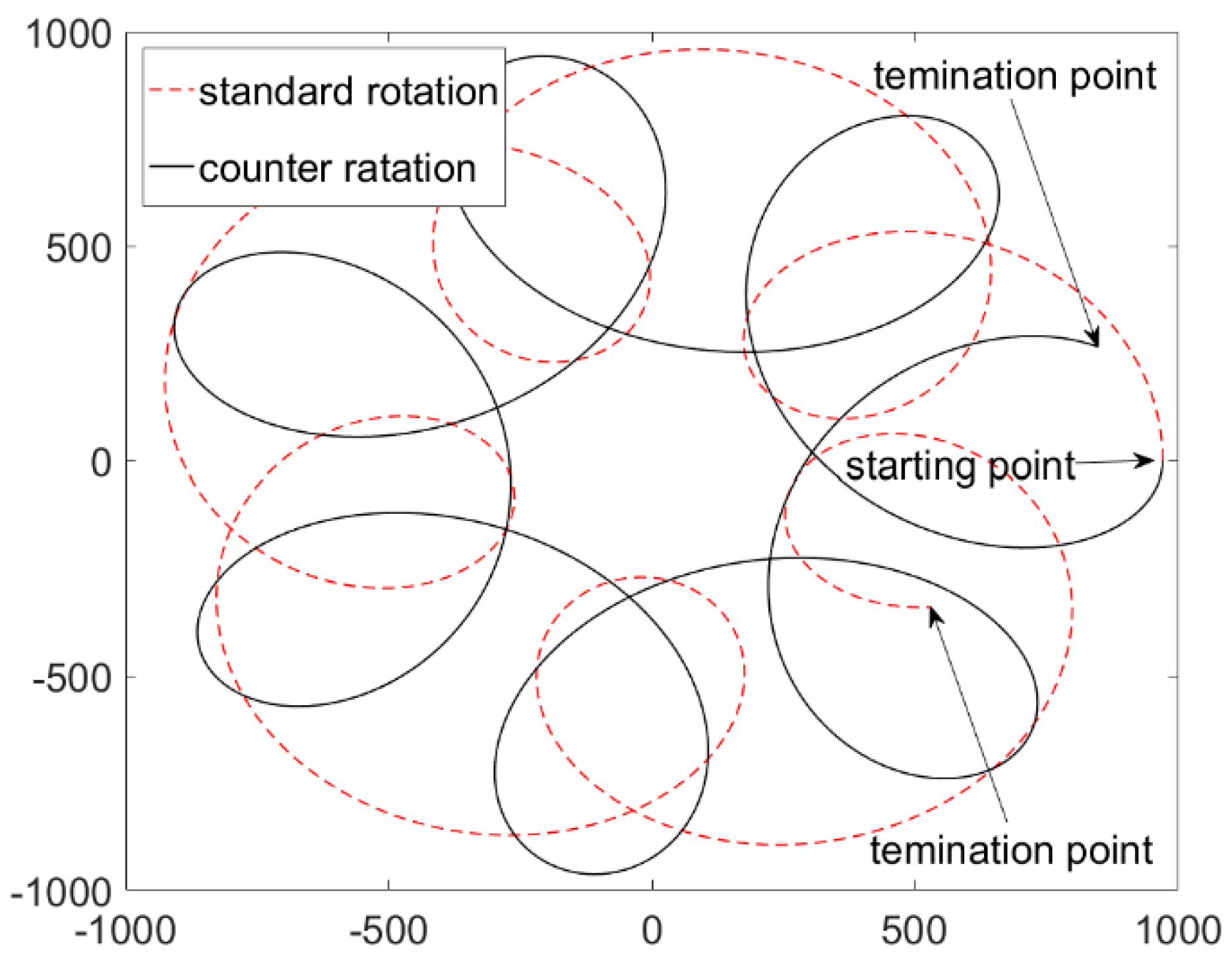
The paths described by a point undergoing a single revolution of the standard and counter PRS are shown in
Figure 4. In a standard rotation, the revolution and rotation are in the same rotation direction as shown by the red line, while the rotation direction of revolution and rotation are opposite in the counter PRS, as shown by the black line.
The paths traversed by a point during 24 revolutions of the PRS are shown in
Figure 5. The geometric configuration is a 2500 mm vacuum chamber with a planetary gear ratio
of 217/37; the radius of the planet orbit
is 620 mm; the radial position of the point on the planet
ρ is 350 mm and the height of the point is 1500 mm. It is apparent that the two paths are very different because the point pass tracks overlap much more at the edge for the standard PRS, whereas they overlap more in the center for the counter PRS.
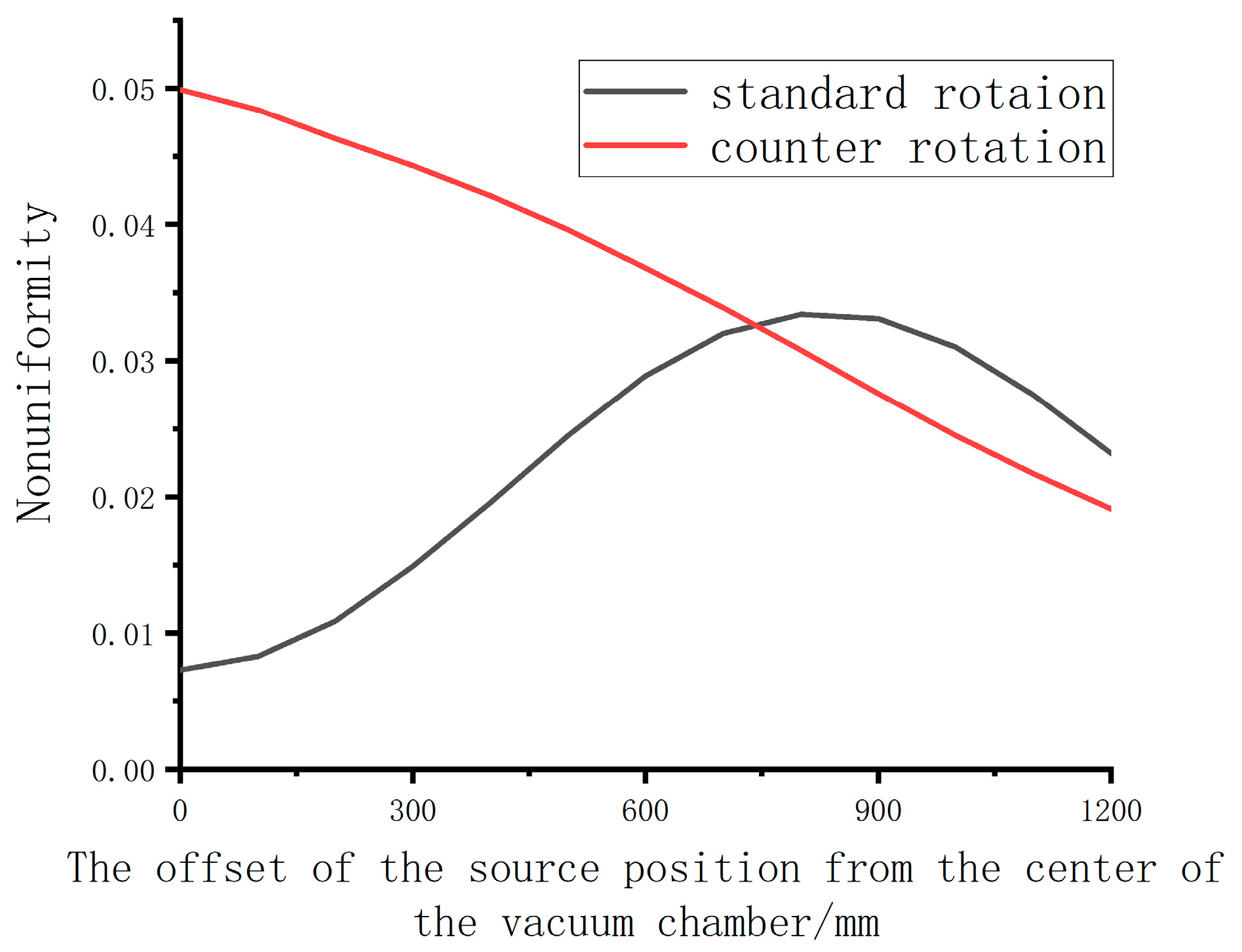
Moreover, there is a difference in the uniformity of the two paths when the evaporation source is at the same location. Therefore, the influence of the evaporation source on the film uniformity should be considered for the standard and counter PRSs. For the 0–350 mm range, the relationship between the film nonuniformity and the offset of the source position from the center of the vacuum chamber is shown in
Figure 6.
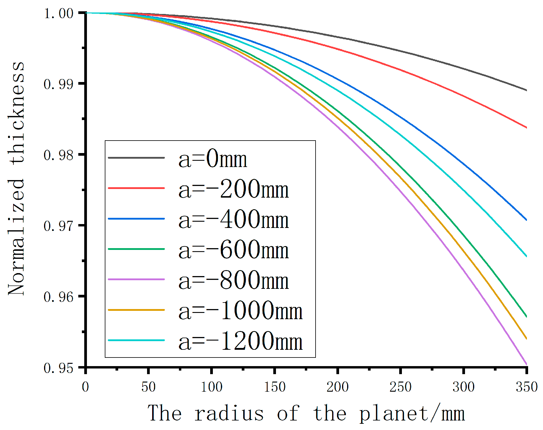
In the counter PRS, the nonuniformity of the film thickness decreases gradually as the offset of the source position from the center of the vacuum chamber increases. However, the nonuniformity of the film thickness does not decrease until the offset of the source position exceeds 900 mm in the standard PRS. The film thickness distribution is shown in
Figure 7 as a function of the radius of the planet between 0 and 350 mm in the standard PRS. Simulations were performed based on source coordinates (in millimeters) of (a, 0, 0), with the values of a varying from 0–1200 mm.
As shown in
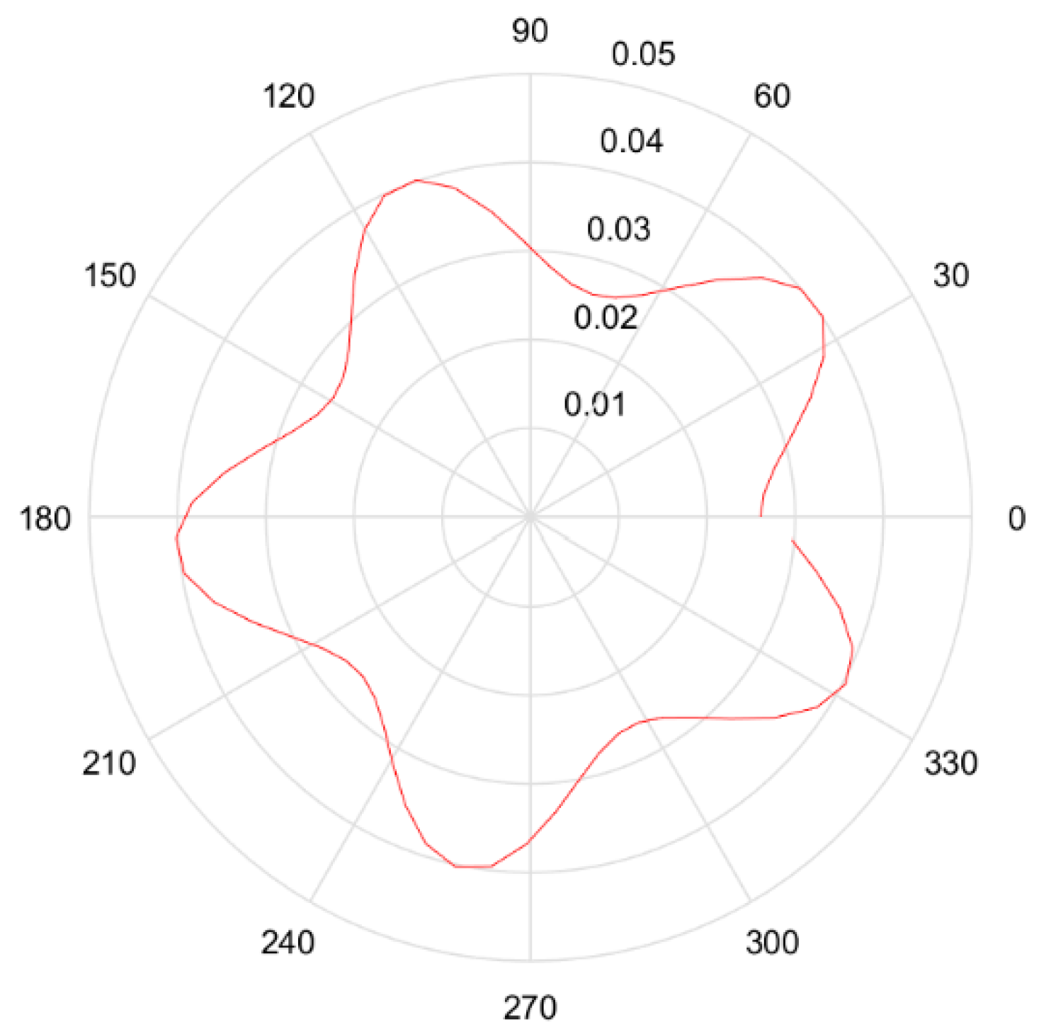
Figure 7, the film thickness decreases gradually over the surface of the reflective mirror with the magnitude of a increasing from 0–800 mm. This behavior was analyzed in greater depth using the polar diagram shown in
Figure 8, for which the polar diameter represents the thickness of the point at 350 mm along the radius of the planet and the polar angle represents the angular position
of the planet in its orbit. The area enclosed by the curve can characterize the film thickness during the N revolutions.
Figure 9 shows the sum of the film thickness at the point 350 mm along the radius of the planet after 37 revolutions, for which the evaporation source is in different positions. It is apparent that the film thickness is much greater at the coordinate (0, 0, 0) of the source position than that at the coordinate (−900, 0, 0) for angular positions ranging from (−2π/3) to (2π/3).
According to the above analysis, there are two locations of the evaporation source at which the surface of the reflective mirror achieves greater uniformity. One is in the center of the vacuum chamber for the standard PRS and the other is close to the chamber wall for the counter PRS. The source in the center can even achieve uniformity below 1%. However, there are two problems that are difficult to overcome:
- (1)
It is very inconvenient to fill film materials because the evaporation source is far from the chamber door.
- (2)
Generally, two evaporation sources need to be placed in the vacuum chamber. Yet, if the two evaporation sources are placed in the center of the chamber, they will contaminate each other during the coating process.
In summary, the optimal solution is that the two evaporation sources are placed symmetrically, close to the chamber wall in the counter PRS.
3.2. Impact of Number of Planetary Revolutions on Film Thickness Uniformity
Oliver demonstrated that the different gear ratios have a significant effect on the film thickness uniformity, while the gear ratio must be nonintegral such that the cycloid traced out is no longer a closed path. However, the number of revolutions also affects the uniformity, as evidenced by
Figure 10. Within 20 revolutions, the uniformity of the film thickness changes drastically because the path traversed by a point changes constantly with the number of revolutions. After more than 20 revolutions, the uniformity of the film thickness stabilizes. Thus, it is necessary to determine the number of revolutions according to the film thickness and deposition rate when measuring the uniformity.
3.3. Impact of the Height of the Optical Element on Film Thickness Uniformity
Another variable that has a significant effect on the uniformity of the film thickness is the height of the optical element.
Figure 11 shows the relationship between the height of the optical element and the film thickness uniformity. It can be seen from
Figure 11 that the uniformity of the film thickness decreases gradually as the height of the optical element increases from 800–1500 mm. This also means that the difference in film thickness decreases from the center of the surface to its edge. However, after exceeding a height of 1500 mm, the uniformity of the film thickness no longer changes significantly.
To analyze the relationship between the height and the uniformity of the film thickness, Equation (4) is revisited. Both cos
ϕ and cos
θ range from 0 to 1. Disregarding the evaporation source position, the square of the radius r can be expressed as
It can be seen from Equation (12) that the value of r is determined by ρ and . The influence of on is much greater than that of ρ. In addition, is a monotonically decreasing function. Therefore, as the height increases, the influence of ρ on the film thickness becomes gradually smaller and the film thickness from the center to the edge of the surface tends to be uniform. In summary, we can increase the height of the reflective mirror to enhance the uniformity of the film thickness. However, increasing the height of the reflective mirror excessively not only fails to improve the uniformity of the film thickness but also increases the difficulty of connecting the reflective mirror and the plate.
Although the film thickness distribution is analyzed using the theory in
Section 2, the theory still has some limitations:
- (1)
This theory only applies to planar evaporation sources. However, in the actual coating process, as the film material decreases, the shape of the evaporation source changes from a flat surface to a spherical shape. So actual results will be different from simulation results.
- (2)
The PRS has design and construction errors, for example, there is a title present in the surface to be coated. These errors will affect the actual results, but the simulation process does not include error analysis.
4. Shadow Mask Design
A stable geometric configuration was optimized, with a gear ratio of
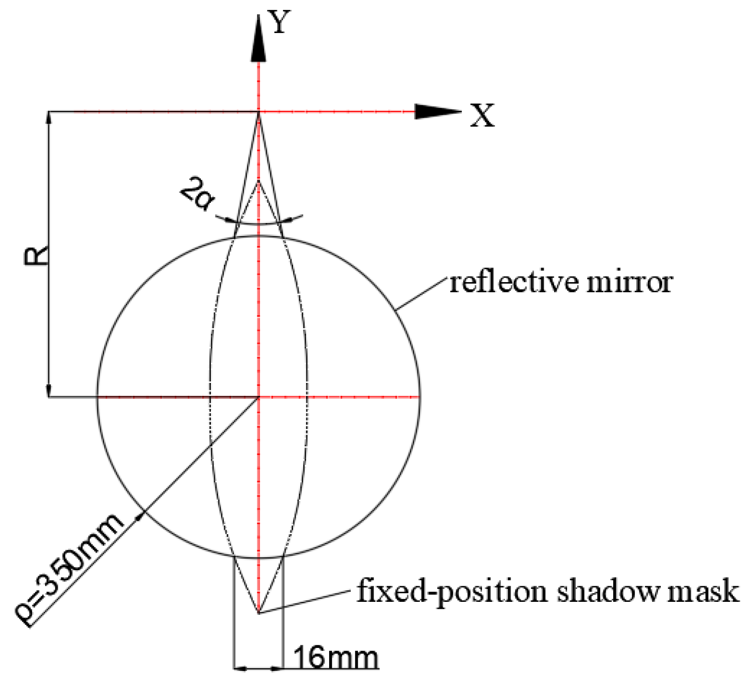
= 217/37, a reflective mirror height of 1500 mm and an evaporation source location of (−900, −300, 0). Residual thickness nonuniformities can be removed via masking. There are multiple methods for masking the vapor plume. Fixed-position masking is the simplest method, requiring low maintenance and offering high mechanical reliability. Two critical aspects of this masking system are the proper mounting of the mask in the coating chamber and the shape of the shadow mask. The mask is placed at a negative
Y-axis position, as shown in
Figure 12, and is parallel to the bottom of the vacuum chamber. Furthermore, to reduce the projection of the mask on the surface of the reflective mirror, the vertical distance between the mask and the reflective mirror is restricted to a few millimeters.
The thickness of the obscured film is determined by the shape of the shadow mask. Therefore, the critical issue in the design of a shadow mask is the determination of the film thickness in the area of the shadow mask. To analyze the film thickness in a certain area, we need to start from the path. The path, describing a point at
ρ = 350 mm in the system with a 217/37 gear ratio and a solar radius of 620 mm undergoing a single revolution, is shown in
Figure 13. The path passes through the shadow mask on three occasions. The path is complicated, and we cannot calculate the thickness obscured when the point passes through the shadow mask accurately. However, we can make reasonable assumptions to approximate the film thickness obscured by the shadow mask:
- (1)
When the film is sufficiently thick, the film thickness at the points with equivalent radii is equal in the reflective mirror.
- (2)
The film thickness obscured by the shadow mask is the same each time the point passes through the mask.
The film thickness obscured by the shadow mask is denoted as
tob, which, at a certain radius, can be determined by the following formula:
where α is the central angle of the shadow mask width relative to the center position of the vacuum chamber. The total film thickness obscured by the shadow mask is three times greater than
. The width of the shadow mask at a certain radius is a function of the obscured position and the central angle:
According to Equations (13) and (14), the calculation process for the design of the shadow mask can be divided into the following steps:
- (1)
according to Equation (7), the film thickness distribution is calculated at different radius positions in the reflective mirror;
- (2)
assuming that the edge width of the shadow mask is known, the film thickness obscured by the shadow mask can be calculated by Equation (13);
- (3)
the film thickness that needs to be obscured at different radius positions is calculated sequentially to obtain tob;
- (4)
the value of α can be obtained according to Equation (13);
- (5)
according to Equation (14), the width of the shadow mask is calculated at different radius positions for the reflective mirror.
The following is a specific example to demonstrate the entire process of designing the shape of the shadow mask. The CA of the reflective mirror is 700 mm (i.e., the range of
ρ is 0–350 mm); the RoC is 1250 mm and the height of the element is 1500 mm. The coordinates of the evaporation source are (−900, −300, 0) and
n = 2. The film thickness distribution on the surface of the reflective mirror is shown in
Figure 14.
As shown in
Figure 14, the film thickness at the edge of the reflective mirror is 215.8 nm (
ρ = 350 mm) and the width of the shadow mask at the edge is 16 mm. According to Equation (13), the film thickness obscured by the shadow mask is 5.1 nm and the
= 5.1/3 = 1.7 nm, with Equation (14) yielding α as 0.005. After being obscured, the thickness of the film at the edge of the reflective mirror is 210.7 nm. This means that the film thickness at other obscured radius locations should also be 210.7 nm.
Table 1 shows the film thickness distribution at different radii of the reflective mirror, as well as the associated obscured thicknesses and widths of the shadow mask.
The initial shape of the shadow mask is shown in
Figure 15a. According to the experiments, the final shadow mask is obtained by making two to three adjustments based on the initial shape; the final shape of the shadow mask is shown in
Figure 15b. Once the shadow mask is installed in the correct position, the remaining nonuniformity is reduced to less than 1%.
Figure 16a,b shows the interference diagrams of the surface before and after the application of the thin film coating, respectively. It is observed that there is almost no variation in the surface profile accuracy, which means that the nonuniformity of the film thickness is controlled with high precision.
5. Conclusions
To investigate and exploit the uniformity of the film thickness in the PRS, we used simulation to study the film thickness distribution. In this article, we report a close relationship between the uniformity of the thin film thickness, which affects the surface profile of the reflective mirror, and the geometric configuration in the vacuum chamber by using the film thickness distribution formula based on Knudsen’s laws. The impact of the evaporation source position on the film thickness uniformity was analyzed for both the standard and counter PRSs. According to the simulation results, the reflective mirror achieves better uniformity when the source is offset from the center of the chamber in the counter PRS. Moreover, the number of planetary revolutions and the height of the reflective mirror also affect the uniformity. The above simulation analysis results can be used to determine suitable positions of the evaporation source and optical components to improve the uniformity of the film thickness. Furthermore, the developed model has been shown to be effective for designing suitable masks to correct thickness nonuniformities. The viewpoint from the movement path proposed in this study potentially offers new insights into the shadow mask design, which would effectively require a reduced number of experiments. In general, by adjusting the geometric configuration and installing the shadow mask, the nonuniformity of the 700 mm concave reflective mirror is reduced to less than 1%.
6. Outlook
Despite these results, there are still some aspects that are not satisfactory. First, we did not consider the effect of extended sources on the film thickness uniformity. Second, the calculation of the film thickness obscured by the shadow mask is not sufficiently accurate, necessitating three to four further modifications of the initial mask shape. Third, with the development of remote sensing satellites, off-axis reflective optical systems are gradually replacing coaxial reflective optical systems, so off-axis mirrors will be widely used in the future. However, due to the limited length of the article, we have not studied the film thickness uniformity distribution for off-axis mirrors in the PRS.
Therefore, we will improve subsequent studies of the uniformity in three primary areas: (1) an improved description of the impact of extended sources to more accurately fit the film thickness distribution; (2) the effect of a movable evaporation source on the film thickness distribution; (3) the accurate determination of the film thickness obscured by the shadow mask; (4) the research on the distribution of film thickness of the off-axis mirror in the PRS.


