Review

Ferroelectric and Ferroelastic Domain Related Formation and Influential Mechanisms of Vapor Deposited Piezoelectric Thin Films

State Key Laboratory of Metal Matrix Composites, School of Materials Science and Engineering, Shanghai Jiao Tong University, Shanghai 200240, China
*
Authors to whom correspondence should be addressed.
Coatings 2021, 11(12), 1437; https://doi.org/10.3390/coatings11121437
Submission received: 21 September 2021 / Revised: 28 October 2021 / Accepted: 28 October 2021 / Published: 24 November 2021
(This article belongs to the Special Issue Nanocomposite Thin Film and Multilayers)

Abstract

:
Compared to the bulk piezoelectric materials counterpart, piezoelectric thin films (PTFs) possess advantages of smaller size, lower power consumption, better sensitivity, and have broad application in advanced micro-electro-mechanical system (MEMS) devices. However, the performance of MEMS transducers and actuators are largely limited by PTFs piezoelectric properties. In this review, we focus on understanding structure-property relationship of vapor deposited PTFs, with emphasis on the effect of strain energy and electrostatic energy in thin films, especially, energy relaxation induced misfit dislocation and ferroelectric (FS) and ferroelastic (FC) domain formation mechanisms. We then discuss the microstructure of these domains and their influential mechanisms on piezoelectric properties, as well as the domain engineering strategies (i.e., internal and external stimuli). This review will motivate further experimental, theoretical, and simulation studies on FS and FC domain engineering in PTFs.

1. Introduction

With the development of science and technology, electronic devices and optoelectronic devices are moving towards miniaturization, integration, and intelligence. Components made of traditional bulk piezoelectric materials have problems such as large size, high power consumption, high cost, and limited operating frequency, while micro-electro-mechanical system (MEMS) devices using piezoelectric thin films (PTFs) have the advantages of small size, low power consumption, and great sensitivity [1,2,3,4,5]. Common applications of PTFs are composed of surface acoustic wave devices [6,7], non-volatile random access memory devices [8,9], infrared sensors [10,11], optical waveguide modulators [12,13], and nanogenerators for energy harvesting [14,15]. In addition, most PTFs are complex ceramic thin films exhibiting complex stoichiometry, co-existence of multiple phases, and various domain morphology, which greatly contribute to functional properties, such as piezoelectricity, dielectricity, and ferroelectricity [16,17]. Therefore, PTFs have drawn great attention from both electronic engineering and materials engineering communities.
Due to the influence of substrates, thicknesses, and atomic growth kinetics, PTFs exhibit distinct characteristics compared to its bulk counterpart. Most literature focuses on the relationship between microstructure and properties, with particular emphasis on the link between piezoelectric properties and the compositional characteristics of doping [18,19,20,21], multi-phases [22,23,24,25], etc. In fact, piezoelectric properties mainly originate from piezoelectric response of domain characteristics, such as domain volume fraction, domain size and domain wall/interface density, and mobility [26,27,28,29]. Conventionally, domains in perovskite structure piezoelectric materials can be divided into two categories: ferroelastic (FS) domains and ferroelectric (FC) domains [30]. FS domains are usually generated by accommodating internal mechanical strain or stress of thin films, such as biaxial residual stress. In comparison, FC domains are introduced by electrostatic energy to maintain uniform charge distributions. As shown in Figure 1a,b, the piezoelectric constant d33 decrease with decreasing a-domain fraction α [31,32], while another piezoelectric constant d31 increases with decreasing domain size [33]. Generally, both FS and FC domains with a large size often reduce piezoelectric properties as a consequence of excessive back-switching [34]. In addition, domain wall/interface density and mobility of have influence on piezoelectric properties. For example, high-density of domain walls usually causes the enhancement of the piezoelectric response [35,36,37], while immobile domain walls with restraining mechanical and electrical recovery lead to the reduction of the piezoelectric response [38]. As shown in Figure 1c, Nagarajan et al. compared continuous PTFs with patterned discrete island PTFs, and found that the motion of the FS domain wall could enhance the piezoelectric response. Patterned discrete island PTFs with high-density mobile domain walls may adapt to the change of the applied electric or stress field [39], and thereby generate a strong piezoelectric response. Thus, controlling of domain structures in PTFs is essential for optimizing the piezoelectric properties [40].
FS and FC domain structure characteristics of PTFs are also influenced by growth mechanisms. PTFs growth includes sol-gel method and physical vapor deposition (PVD). The comparison of their mechanism, main process, advantages and drawbacks are shown in Table 1.
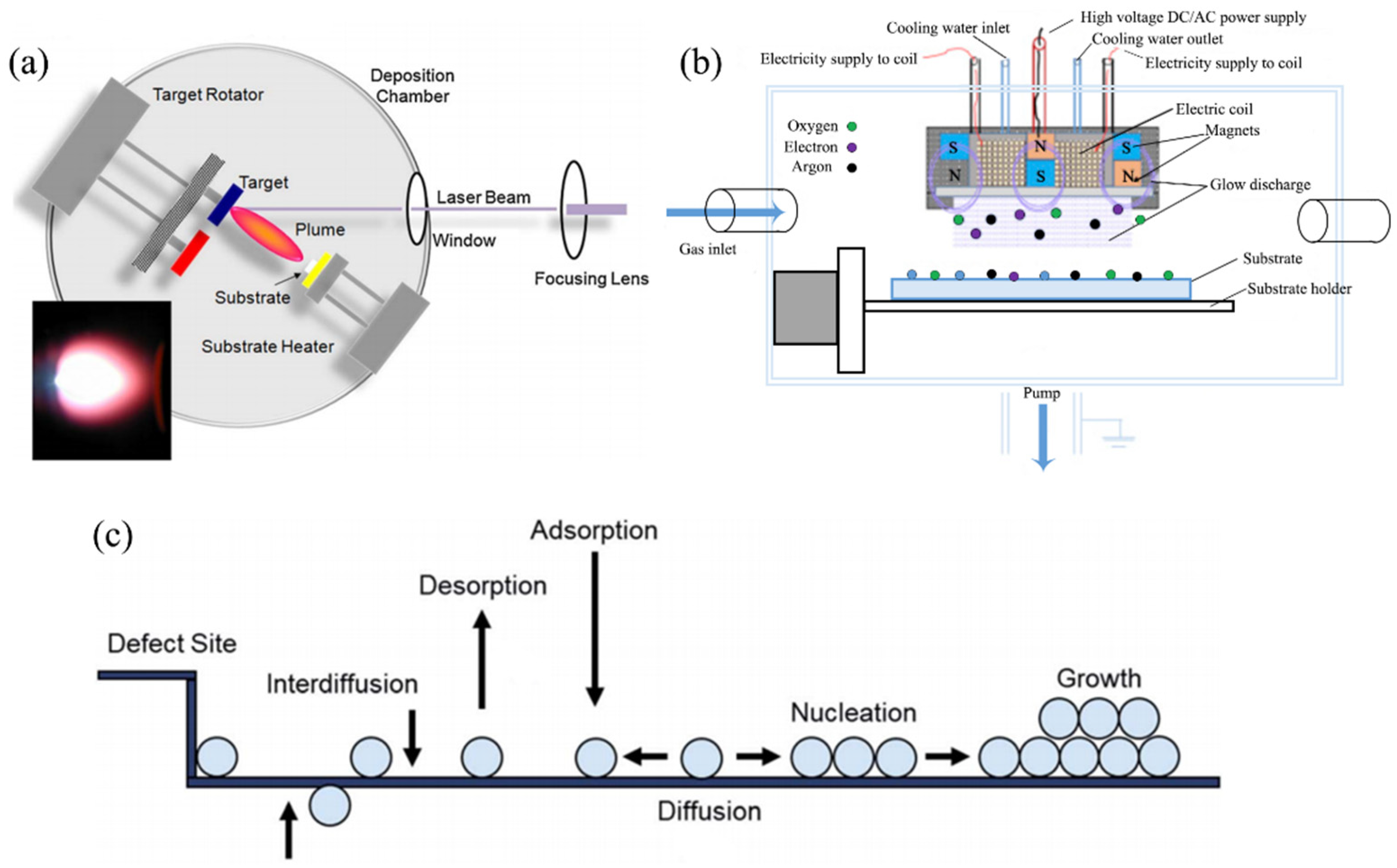
The sol-gel method applies liquid compounds with highly chemically active components as precursors to synthesize PTFs. In comparison, PVD method promotes the transfer of atoms from a solid or molten source to a substrate by physical methods, without chemical reaction. Therefore, PVD method has potential to provide large-scale films with high quality and controllable thickness [41]. Therefore, plenty of researches are focused on this field including electronic device designing, PVD fabrication techniques [42], and materials structure-property relation [43]. For fabricating PTFs, pulsed laser deposition (PLD) and magnetron sputtering deposition (MSD) are two common PVD techniques. Figure 2a,b are schematic diagrams of PLD and MSD, respectively [44]. These two methods show similar atomic growth process, which can be described as: (1) evaporation of target atoms, (2) adsorption or desorption, (3) surface diffusion or interdiffusion, (4) chemical bonding at substrate and nucleation, (5) thin-film formation and growth, as shown in Figure 2c [45]. The major differences between them are attributed to their evaporation approaches (Laser beam for PLD [46] vs. ion bombardment for MSD [47]). Variation of PTFs growing process can be influenced by adjusting film/substrate system characteristics or applying external stimuli, and then give rise to modulate domain structures. Therefore, it is significant to understand the PVD growing process of PTFs, especially the formation and influential mechanisms of domain structures under various film/substrate system and external stimuli.
In this review, we focus on the domain related formation and influential mechanisms of PTFs prepared by PVD. To address this topic, we first discuss energy release mechanisms in Section 2. During the growth process, PTFs encounter island or layer-by-layer growth mode, generation of misfit dislocations and formation of domain structures. In Section 3, based on the relaxation of strain energy and electrostatic energy, we then discuss the influence of various PTF/substrate system on domain structures in PTFs. We mainly focus on the specific characteristics of substrate, film and electrode. In Section 4, we discuss the influence of external stimuli on domains microstructures of PTFs. We briefly introduce the influence of external electric field and mechanical stress. Finally, we summarize domain related formation and influential mechanisms and give an outlook of the future research direction in Section 5. We hope this review could stimulate opportunity to piezoelectric domain engineering in the future.

2. Energy Associated Nucleation and Formation Mechanisms

PTFs are quite different compared to bulk piezoelectric materials, because they are clamped by the substrate and produce mechanical and electrical boundary conditions. As a result, the strain energy and electrostatic energy are generated. Therefore, during the PVD process, PTFs exhibit a complex energy relaxation mechanism, including the variation of growth modes, generation of misfit dislocations and formation of domain structures.

2.1. Variation of Growth Modes

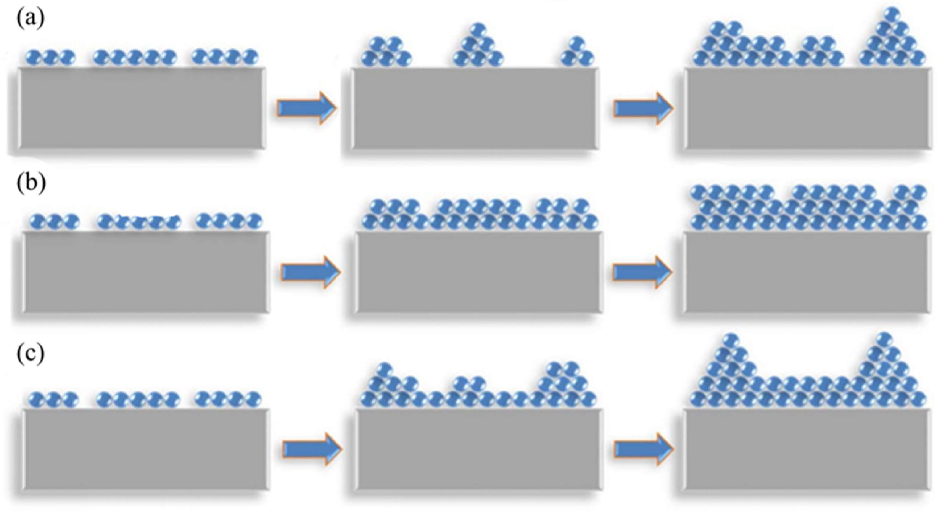
Island growth mode, layer-by-layer growth mode and layer plus island growth mode have been so far classified [48,49]. Thermodynamic theory believes that the interface energy between the film and the substrate (γfs), the surface energy of the film (γf) and the substrate (γs) determine the growth mode [50]. That is, (1) island growth mode for γs < γf + γfs; (2) layer-by-layer growth mode for γs > γf + γfs; (3) layer plus island growth mode for γs > γf + γfs at the early stage and γs < γf + γfs at the later stage. The schematic diagrams of these three growth modes are shown in Figure 3 [46]. If γs < γf + γfs, it is energetically favorable for adatoms to form three-dimensional clusters or islands on the surface of the substrate. Adatoms tend to combine with their own weakly bound atoms and thin film growth proceed by the growth of islands until they coalescence, which is called island growth mode (Volmer–Weber growth mode), as indicated in Figure 3a. Many metal thin films deposited on insulators exhibit this growth mode. On the other hand, if γs > γf + γfs, adatoms are more likely to bond with the substrate atoms. Once adatoms clusters form on the surface, other adatoms tend to attach to the cluster at its periphery where they bond with both substrate and thin film atoms. As a consequence, thin film exhibits the planar growth, which is called the layer-by-layer growth mode (Frank van der Merwe growth mode), as indicated in Figure 3b. It requires that the lattice mismatch between the film and the substrate is quite small and the epitaxy films usually exhibit this growth mode. If γs > γf + γfs at the early stage, the first few monolayers are grown layer-by-layer, and as PTFs deposition procress, the tendency is reversed into γs < γf + γfs, subsequent adatoms tend to gather into islands rather than continue the planar growth. This process combines the characteristics of island growth mode and layer-by-layer growth mode, called layer plus island growth mode (Stranski–Krastanovs growth mode), as indicated in Figure 3c. It is usually found in metal-metal or semiconductor-semiconductor systems, especially for lattice mismatch and strained layer growth [51]. Therefore, the changes in surface energy and interface energy may lead to the variation of growth modes.
For different PTFs deposited on different substrates, these three growth modes are mainly determined by the lattice mismatch. If the lattice mismatch is large, the interface energy γfs is large enough to satisfy the equation γs < γf + γfs, and PTFs may grow directly in island growth mode [52]. On the contrary, if the lattice mismatch is small, the smaller γfs is more likely to cause γs > γf + γfs, so that PTFs could grow in layer-by-layer growth mode. By comparing the cross-sectional morphology of PbZr0.52Ti0.48O3 and PbZr0.2Ti0.8O3 films deposited on SrRuO3-buffered SrTiO3 substrate, Nagarajan et al. find that the two different films deposited on the same substrate exhibit different growth modes. The PbZr0.2Ti0.8O3 film has a smoother surface, and the layer-by-layer growth mode occurs. Due to the small lattice mismatch (−0.7%) between PbZr0.2Ti0.8O3 and SrRuO3, the film matches the bottom electrode well, so the film could grow in layer-by-layer mode. In comparison, the PbZr0.52Ti0.48O3 film has a rough surface, indicating that it grows in the island growth mode due to the lattice mismatch of −3.93% between PbZr0.52Ti0.48O3 and SrRuO3 [53,54]. For the same film deposited on different substrates, lattice mismatch could also lead to different growth modes. When BaTiO3 is deposited on an SrTiO3 substrate with a small lattice mismatch, BaTiO3 grows in the layer-by-layer growth mode [55,56]. On the contrary, when BaTiO3 is deposited on MgO substrate with a large lattice mismatch, the film grows in the island growth mode [57]. Through these two sets of comparative experiments, it can be demonstrated that on the same substrate, the types of PTFs are different, and the lattice mismatch between PTFs and the substrate is different, which may lead to different growth modes. Similarly, the same PTFs deposited on different substrates may also form different growth modes.
For PTFs and substrate with moderate lattice mismatch, PTFs usually grow in layer plus island growth mode. At the initial stage, the mismatch is not large enough to form islands, so that PTF could grow layer by layer. However, the strain energy generated by the lattice mismatch between PTFs and the substrate increases with the increase of deposition layers [58]. In order to release these strain energy, once the film grows beyond a critical thickness, strain islands are formed on the PTF surface by sacrificing γf [59]. Therefore, γs < γf + γfs is satisfied and island growth mode becomes favorable. As a result, the growth mode will change from the layer by layer growth mode to the island growth mode [60,61]. Visinoiu et al. deposited BaTiO3 films on the vicinal SrTiO3 (001) substrate through PLD, and observed the changes in surface morphology through atomic force microscope (AFM) and transmission electron microscopy (TEM) [62]. As shown in Figure 4a–f, with the film deposition process, the surface of PTF gradually changes from smooth to rough. At the beginning of deposition process, a smooth surface means that the film grows layer by layer. In the later stage of deposition, the growth mode of BaTiO3 changes to the island growth mode to release the mismatch between the film and the substrate. The rough surface of the film proves the existence of the island growth mode. In other words, it can be seen that the BaTiO3 film grows from layer-by-layer to island growth mode. The variation of growth modes observed in the experiment is consistent with the conclusion obtained by theoretical calculation by Kang et al. [63]. Overall, PTFs could change growth modes from layer-by-layer to island growth mode during deposition process in order to release the strain energy.
Besides the thermodynamics, PTFs growth modes are also affected by the kinetics caused by the preparation conditions [64,65]. It is demonstrated that the pulse repetition rate, deposition temperature and gas pressure are all effective methods to adjust the growth mode of PTFs. In general, the preparation conditions which can increase the mobility of adatoms are beneficial to the layer-by-layer growth mode [66]. On the contrary, the preparation conditions which impede adatoms migration or increase the barrier of adatom transition stimulate the island growth mode. For example, reducing the pulse repetition rate could enhance the layer-by-layer growth mode. Because the decrease in pulse repetition rate will increase the time interval between two laser pulses, adatoms have enough time for surface diffusion to form layer-by-layer growth mode. When the pulse repetition rate is high, the adatoms do not have enough time to diffuse and can only cluster together to form the island growth mode [67,68,69]. Increasing the deposition temperature will enhance the surface diffusion of adatoms, making it easier to overcome the layer transition barrier and as a result, forms the layer-by-layer growth mode. In contrast, when the deposition temperature is low, PTFs exhibit the island growth mode because of the weak diffusion ability of adatoms [70,71]. Kang et al. prepared PZT films with different deposition temperature by MSD. Without changing other preparation conditions, the surface topography shows that as the deposition temperature increases, the growth mode changes from island growth to layer-by-layer growth [72]. That is, higher deposition temperature increases the kinetic energy of adatoms, which is conducive to the formation of layer-by-layer growth mode. PTFs deposited at the low gas pressure will lead to layer-by-layer growth mode. It is demonstrated that the adatoms will collide less during the movement on the substrate at lower gas pressure. Therefore, they maintain high mobility rate on the surface of the film, resulting in the layer-by-layer growth mode. Whereas the excessive gas pressure will hinder the diffusion of adatoms, causing PTFs to grow in the island growth mode [73,74,75]. In conclusion, the growth mode can also be changed by adjusting the preparation conditions to release energy.

2.2. Formation Mechanisms of Misfit Dislocations

Besides the variation of growth modes, the generation of misfit dislocations is also a significant way to release energy during the early stage of PTFs growing process. Different from metal or semiconductor thin films [76,77,78], PTFs will undergo a phase change from paraelectric (PE) phase to ferroelectric (FE) phase during the temperature drops to Curie temperature ( T C ), accompanied by a decrease in the crystal symmetry. The deposition temperature ( T g ) for PTF is usually higher than T C , when PTF is the PE phase. For example, T C of BaTiO3 and PbTiO3 is about 130 and 450 °C, respectively, while T g is above 600 °C [79]. At this stage, the relaxation of the energy is mainly accomplished by the formation of dislocations [80,81,82].
The generation of misfit dislocations occurs at the certain thickness of PTFs [83,84]. During PTFs growing process, when the thickness is equivalent to one or a few atomic layers, the mismatch between the interfaces is relaxed by uniform elastic strain [85,86]. As the thickness increases, strain energy gradually increases. After exceeding a critical thickness h C , PTFs will generate misfit dislocations and partially relax the total energy of the system [87,88,89,90]. Concurrently, the generation of dislocations will increase the dislocation energy. If the strain energy released by misfit dislocations exceeds the energy increased by the generation of dislocations, the misfit dislocation could exist. When these two energies are exactly equal to each other, the critical thickness h C for the generation of misfit dislocation can be calculated as [91]:
h c = l ( h c ) ε m ( 1 + ν )
where ε m is misfit strain, ν is Poisson’s ratio, l ( h c ) is given as
l ( h ) = | b | 8 π cos λ ( 1 ν cos 2 β ) ln ( α h | b | )
where λ is the angle between the Burgers vector and the direction normal to the misfit dislocation line, β is the angle between the Burgers vector and the dislocation line. For PTFs with thickness h < h C , they could maintain the coherence with the substrate lattice, while sacrificing the elastic strain energy of the film lattice. As the thickness of the film increases, the elastic strain energy increases linearly with the thickness, eventually exceeding the energy required for the generation of misfit dislocations. Therefore, misfit dislocations are generated, which destroy the interface coherence of the film and the substrate, and partially relax the strain energy [92,93,94,95,96]. In the PTFs with tetragonal perovskite structure deposited on cubic or pseudo-cubic (100) substrates, two types of misfit dislocations with the Burgers vector {100} and {110} are usually observed through both simulation prediction [97] and experimental validation [98,99]. Figure 5 shows two types misfit dislocations with Burgers vectors b = a [ 010 ] and b = a [ 011 ] on the BiFeO3/LaAlO3 interface observed by high-angle annular dark-field (HAADF) scanning transmission electron microscopic (STEM) [100]. Both of them contain a [010] component, which could release the misfit strain energy between BiFeO3 and LaAlO3 along their interface.
In addition to releasing energy at T g , the generation of misfit dislocations could influence the following process. Once the misfit dislocations reach the equilibrium density, the effective mismatch between PTFs and the substrate will also change. The equilibrium dislocation density ρ m d is calculated by Mattews et al. [95].
ρ m d = ε m | b | cos λ 1 8 π h cos 2 λ ( 1 v cos 2 β 1 + ν ) ln ( 4 h | b | )
It is reasonable to assume that the misfit dislocation density will not change with temperature during the cooling process. However, misfit dislocations have a screening effect on the substrate, and the lattice constant of the substrate felt by PTF will change. To simplify the following calculation, here we use the effective substrate lattice constant a S * to express the lattice constant after the generation of misfit dislocations,
a s * = a s ( 1 ρ m d | b | cos λ )
The change of a S * will further change the subsequent mismatch strain energy, thereby affecting the energy release of PTFs at lower temperature [101]. In other words, at the early stage of PTFs growth process, generation of misfit dislocations could not only release energy, but also affect the energy releasing later by adjusting the effective substrate lattice constant.

2.3. Formation Mechanisms of Domain Structures
During the cooling process from T g to the room temperature, the formation of domain structures becomes the main way of PTFs energy release. The energy produced in this process could mainly divided into strain energy and electrostatic energy. Strain energy includes: (1) misfit strain energy, due to the lattice mismatch between the film and the substrate; (2) thermal strain energy, due to the different thermal expansion coefficients of the film and the substrate. When cooling to T C , the phase transition will produce spontaneous polarization in PTFs, leading to the formation of surface charges, which form a depolarization field in the opposite direction of the spontaneous polarization. In the presence of the depolarization field, electrostatic energy is generated. In order to release these energy, PTFs form small regions with the same spontaneous polarization, which are called domain structures [102,103,104]. FS domains are formed to release the strain energy and FC domains are formed to release the electrostatic energy.
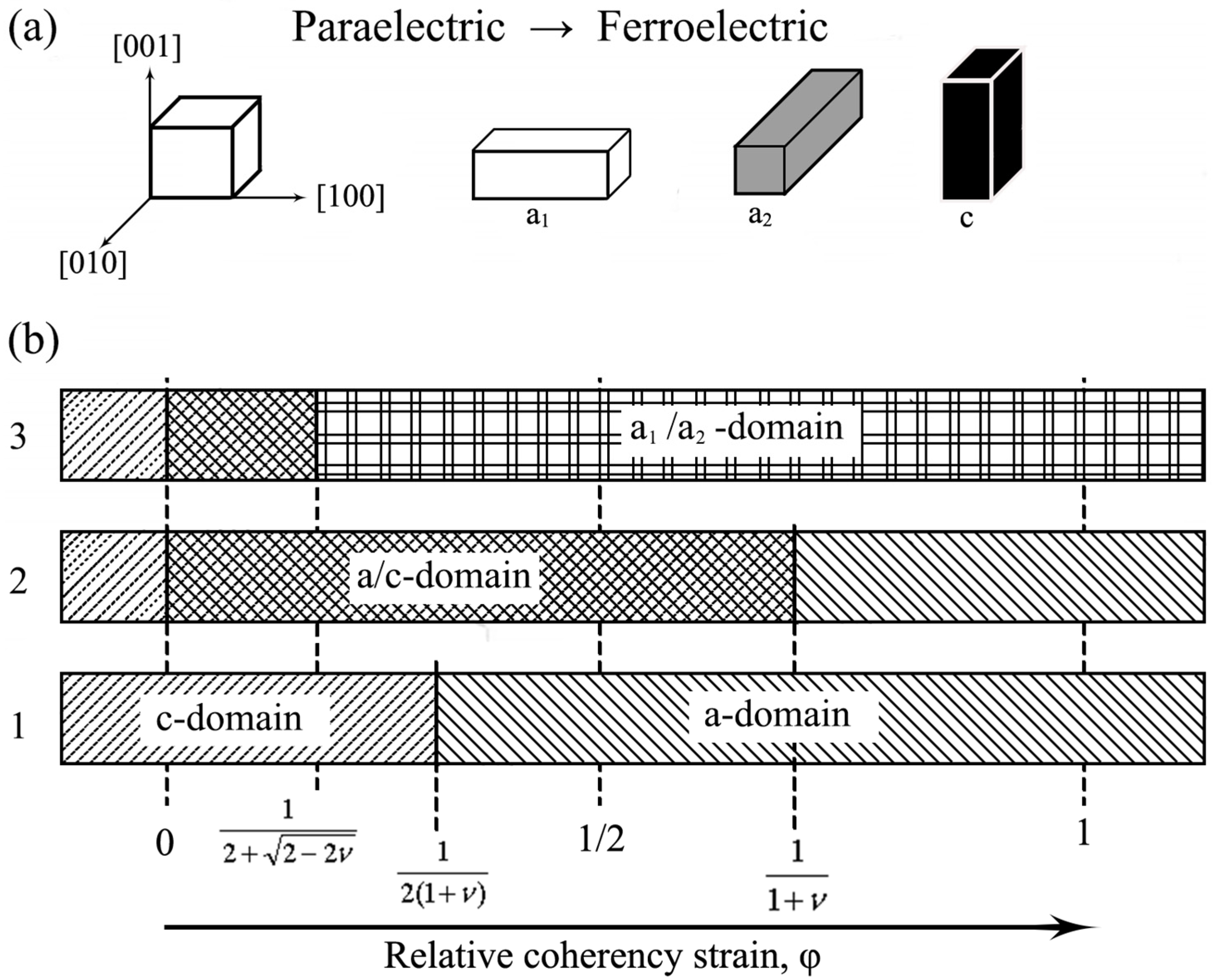
For simplicity, here we consider a simple case of PTF with tetragonal structure. There will be three domain states [105], one with the out-of-plane orientation of the tetragonal axis (c-domain) and two with the in-plane orientation (a1-domain and a2-domain), as shown in Figure 6a. In the following, we discuss the domain formation mechanisms.
The lattice mismatch between PTFs and the substrate can be written as
ε a = a s * a a s *
and
ε c = a s * c a s *
where a and c represent the lattice constants of the tetragonal PTFs. We define a parameter called tetragonality ratio as
χ = ε c ε a = c a s * a s * a
Firstly, we consider the single domain state. For c-domain, the formation energy is
U c = E 1 ν ε a 2 = 2 U 0 ( 1 + ν )
For a1-domain or a2-domain, the formation energy is equal to each other due to their symmetry, which can be described as
U a = 1 2 E 1 ν ( ε a 2 + ε c 2 + 2 ν ε a ε c ) = U 0 ( 1 + χ 2 2 ν χ )
When χ = 1 + 2 ν, the two formation energy terms reach the same. To simplify the calculation, here we consider the relative coherency strain. The c-domain is energetically favorable when φ > 1 / 2 ( 1 + v )   . On the contrast, a-domain is energetically favorable when φ < 1 / 2 ( 1 + v ) .
Then we consider two domain state. Two domain state is favored if the formation energy of the single domain can be diminished by embedding a second domain orientation [106]. Assuming that the fraction of c-domain is α and the fraction of a-domain is 1-α, then two domain state energy can be written as
U a a = E 1 + ν ( ε a ε c ) 2 = 2 U 0 ( 1 + χ ) 2 ( 1 ν )
Comparing U a and U a a , we will find that the energy reaches a minimum value when the fractions of a1 and a2 domains are equal (α = 0.5). In other words, the mixture of a1 and a2-domain always has a lower energy than the single a-domain state. Taking U c and U a c into account, we get a theoretically stable PTFs domain structure state. When φ < 0 , c-domain is favorable and when φ > 1 / ( 2 + 2 2 ν ) , a1/a2-domain is favorable. Between these two critical values, the a/c-domain has the lowest energy. We use Table 2 and Figure 6b to summarize the above analysis.
Figure 6. Domain states in tetragonal PTFs. (a) Three domain states in tetragonal PTFs: a1-domain with [100] polarization; a2-domain with [010] polarization; c-domain with [001] polarization. (b) Theoretical calculation for predicting domain states with different φ in tetragonal PTFs. From bottom to top, (1) single domain state, (2) two domain state of a-domain, and c-domain, and (3) the distinction between a1-domain and a2-domain are taken into account, respectively. Reprinted with permission from [107] 2010 Springer Nature.
Coatings 11 01437 g006

2.4. Domain Configurations in Tetragonal PTFs

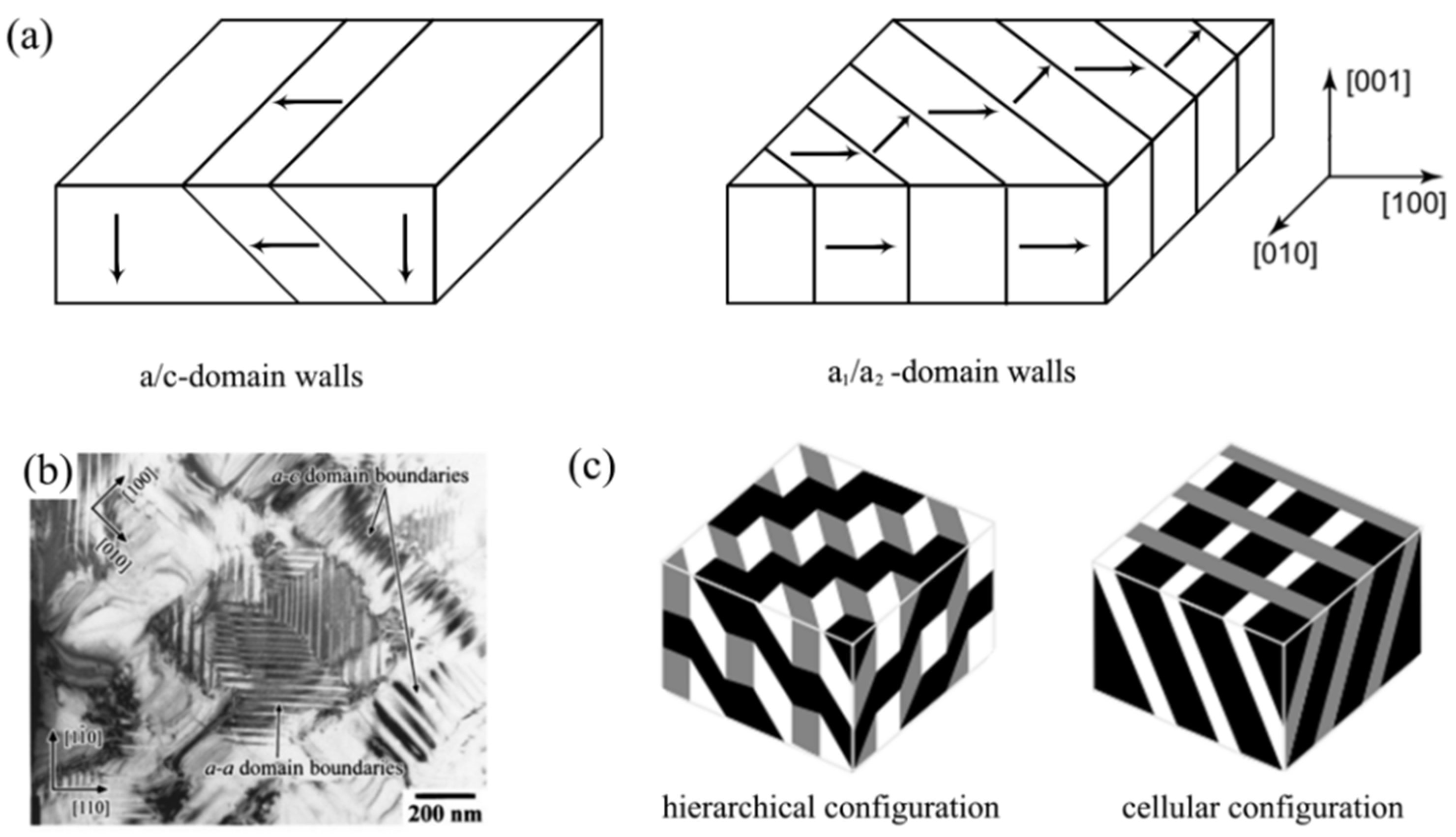
For PTFs with more than one domain states, different domains are separated from each other by domain walls. In the case of PTFs with tetragonal structure, only {110} domain walls are stable. For a/c-domain, domain walls include ( 101 ), ( 1 1 ¯ 0 ), ( 011 ) and ( 0 1 ¯ 0 ), which are nearly 45° inclined to the PTFs/substrate interface. For a1/a2-domain, domain walls include ( 110 ) and ( 1 ¯ 10 ), which are nearly perpendicular to the interface. Figure 7a,b are the schematic diagrams and the experimental observation [108] of these two types of domain walls, respectively.
If PTFs contain all the three domains, two different domain configurations are possible: hierarchical configuration and cellular configuration, as illustrated in Figure 7c [107]. It is demonstrated that when the fractions of the three domain states are similar, hierarchical configuration is energetically favorable. However, when the fraction of c-domain is very large and there are only a few a1 and a2-domain, PTFs tend to exhibit the cellular configuration [30,109].

3. Influence of Film/Substrate System on Domain Structures

As mentioned above, the formation of domain structures in PTFs is generally the result of minimizing the strain energy and electrostatic energy of the film/substrate system. From this, domain structures in PTFs are sensitive to the PTF/substrate system, i.e., characteristics of the substrate, PTF, and electrode. Even small changes in these factors could lead to substantial effects on different strain energy and electrostatic energy in PTFs, and then influence domain structures. Therefore, we briefly introduce the effects of these PTF/substrate system on domain structures here.

3.1. Substrates Characteristics

Different substrates have their unique lattice constants and thermal expansion coefficients, i.e., different lattice mismatches and thermal mismatches will occur between them and PTFs. The selection of suitable substrate can generate appropriate strain in the PTFs and obtain the desired domain structure. The basic principle is: tensile strain is conducive to the generation of a-domain, and compressive strain is conducive to the generation of c-domain [107]. This regular law has already confirmed by both theoretical simulations and experimental validations [110,111].
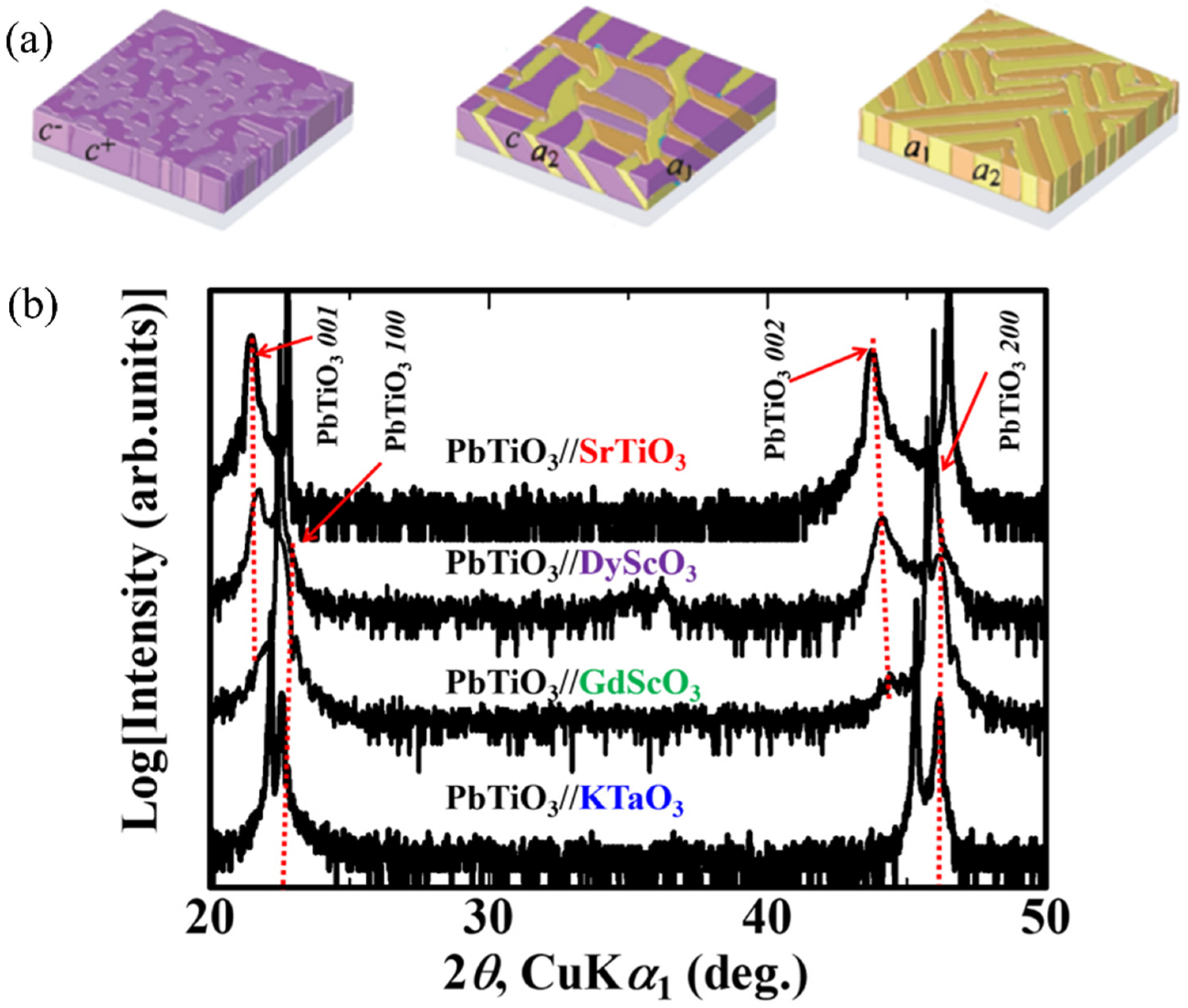
The lattice mismatch between PTF and the substrate is probably the most significant principle when choosing a substrate. Substrate with a larger lattice constant than that of PTF will lead to the tensile strain in PTF. On the contrary, substrate with a smaller lattice constant than that of PTF will result in the compressive strain in PTF. As the strain changes form compressive to tensile, the domain structure changes from c-domain to a/c-domain, and finally to a1/a2-domain. Figure 8a shows the change of domain structures of the BaTiO3 film with strain using the phase field simulation method [112]. From compressive mismatch strain to tensile mismatch strain, domain structure of BaTiO3 changes from single c-domain (left of Figure 8a) to a/c-domain (middle of Figure 8a), and finally evolves into a1/a2-domain (right of Figure 8a). That is, c-domain fraction decreases and a-domain gradually dominates the microstructure. A similar trend of domain structure change was also observed in the experiment. Figure 8b is the X-ray diffraction (XRD) image of PbTiO3 films grown on different substrates [113,114]. The lattice mismatches between PbTiO3 films and SrTiO3, DyScO3, GdScO3, KTaO3 substrates are −1.33%, −0.18%, 0.2%, and 0.5%, respectively. It can be seen that when PbTiO3 is under a large compressive strain, there is almost only (00l) peaks, which means that PbTiO3 is dominated by c-domains. As the tensile strain increases, the (h00) peak appears and gradually becomes stronger, indicating that a-domains are formed and the volume fraction of a-domain continues to increase. This phenomenon is consistent with the trend of the phase field simulation. Therefore, by selecting a suitable substrate, different mismatch strains can be applied to PTFs to tailor the domain structure.
The thermal mismatch caused by the difference in the thermal expansion coefficients between PTFs and the substrates is also a concern. The selection of a suitable substrate can make PTFs generate proper thermal mismatch during the cooling process, and then obtain different domain structures. The thermal stress induced in PTFs during the cooling process can be written as:
σ t h = E 1 ν f ( α f α s ) ( T d T )
where α f and α s represent the thermal expansion coefficient of PTFs and the substrates, respectively. If α s is greater than α f , a compressive stress is produced and the formation of c-domain is advantageous. On the contrary, if α f is greater than α s , a tensile stress is produced and the formation of a-domains is advantageous [115]. Figure 9a,b shows the cross-sectional TEM images of PbTiO3 films deposited on the MgO (001) and KTaO3 (001) substrate by radio frequency MSD [108]. The thermal expansion coefficient of PbTiO3 is α f 12.6 × 10 6 / K , while the thermal expansion coefficients of MgO (001) and KTaO3 (001) substrate are α s 14.8 × 10 6 / K and α s 6.67 × 10 6 / K , respectively. Since the thermal expansion coefficient of the MgO (001) substrate is greater than that of the PbTiO3 film, compressive thermal stress is generated in the film during the cooling process. Therefore, the PbTiO3 film is mainly composed of c-domains, with some a-domains separated by 90° domain walls, as shown in Figure 9a. On the contrary, the thermal expansion coefficient of the KTaO3 (001) substrate is smaller than that of the PbTiO3 film, and the strain caused by the thermal mismatch is tensile. In Figure 9b, we could demonstrate that in the PbTiO3/KTaO3 (001) system, a large number of a-domains can be observed, and a small number of c-domains are embedded in it. For BaTiO3 films prepared by PLD, the formation of domain structure is similar. It is observed that the film is in the c-domain state on the MgO substrate with a higher thermal expansion coefficient [116], whereas for GaAs substrate having smaller thermal expansion coefficient, it shows the a-domain state [117]. Thus, using substrates with larger thermal expansion coefficients could help to obtain a structure with more c-domains at room temperature. On the contrary, if more a-domains are wanted, one can choose a substrate with a smaller thermal expansion coefficient.

3.2. PTF Characteristics

The thickness and composition of PTFs influence the domain structures by affecting the misfit strain energy, which in turn affects the domain structure. PTFs with different thickness have different effective misfit strain. Derived from Equations (1)–(4), the effective substrate lattice constant can be written as
a * = a [ 1 ε m ( 1 h c h ) ]
The effective residual misfit strain as follows
ε m * = a * a c a *
If the film initially produces tensile strain, i.e., ε m is positive, then a * will decrease as the film thickness h increases. The effective residual misfit tensile strain decreases, leading to an increase in the c-domain fraction. On the contrary, if the initial misfit strain in the film is compressive strain, i.e., ε m is negative, the law is reversed. Figure 10a,b shows the variation of c-domain fraction versus film thickness. For PbTiO3 film on the KTaO3 substrate (Figure 10a), the lattice constant of the substrate is 4.003 Å, which is greater than that of PbTiO3 (3.986 Å). Through the epitaxial effect, this causes tensile strain in the film. Therefore, as the deposition thickness increases, the tensile strain relaxes through the formation of c-domain and the c-domain fraction increases [118]. In the case of Pb(Zr0.2Ti0.8)O3 film on the LaAlO3 substrate (Figure 10b), the lattice constant of the substrate is smaller than that of PTF, which results in the compressive strain in the film. Therefore, as the film becomes thicker, the compressive strain is relaxed by the formation of a-domain, so the fraction of c-domains decreases [91].
The influence of PTF composition on the domain structure is mainly manifested by changing the lattice constant [120]. By controlling the Zr/Ti ratio of Pb(Zr,Ti)O3 film, the mismatch strain can be controlled, which in turn affects the domain structure [121]. Figure 10c shows the variation of c-domain fraction with Zr concentration in Pb(Zr,Ti)O3 film prepared by radio frequency MSD [119] that the domain structure of epitaxial PZT thin films are grown on. Because the ion radius of Zr4+ is larger than that of Ti4+, the increase of Zr concentration will lead to the increase of Pb(Zr,Ti)O3 lattice constant [122]. In the film, the compressive strain increases, and the c-domain fraction increases accordingly. A similar rule exists when the film is subjected to tensile strain. Ichinose et al. prepared Pb(Zr,Ti)O3 films on KTaO3 substrate and found that when the Zr content is 0, the film is subjected to a large tensile strain. At this time, the film is almost entirely composed of a-domains. As the Zr content increases, the tensile strain on the film gradually decreases, and the c-domain fraction increases accordingly [123]. Besides the experimental validation, Lee et al. used finite element method and also confirmed that as the Zr concentration increases, the c-domain fraction will increase [124].

3.3. Electrode Film Characteristics

The influence of electrode characteristics is often considered when the film is thinner. This is because the strain energy dominates over the electrostatic energy when the film is thick [104]. Researchers often pay attention to the influence of film and substrate characteristics on domain structures. However, the electrostatic energy increases with the decrease of the film thickness [125]. In ultra-thin PTFs, the influence of electrostatic energy even dominates over the strain energy and must be taken into account [126,127,128].
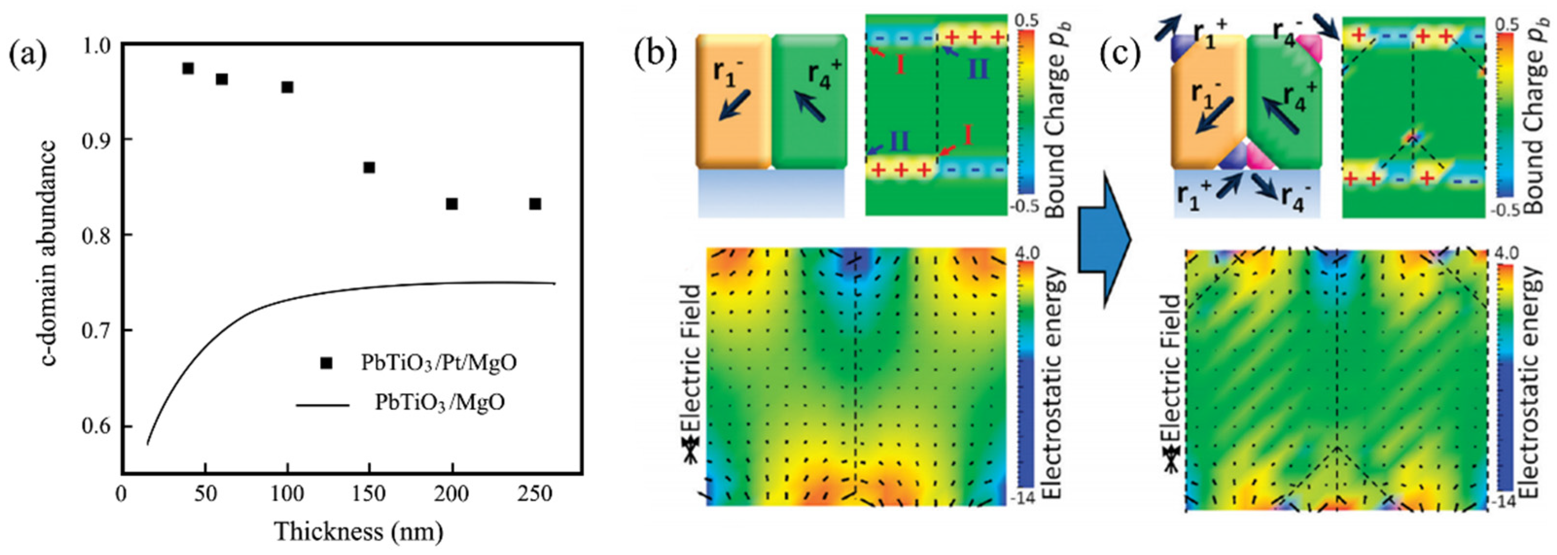
It is demonstrated that using electrodes to move the carriers in a directional direction to shield the depolarization field is an effective way to release electrostatic energy [129,130]. In addition to compensating for the charge caused by the depolarization field to reduce electrostatic energy, the lattice mismatch between the electrode and PTF cannot be ignored. If the lattice constants of the electrode and the substrate are quite different, the presence of the electrode may change the regularity of domain structures in PTFs [131]. Figure 11a shows the c-domain fraction of PbTiO3 films with or without Pt electrode as a function of film thickness [132]. In the absence of Pt electrodes, PbTiO3 is deposited directly on the MgO substrate. Since the lattice constant of MgO is larger than that of PbTiO3, the film is under tensile stress, so the c-domain fraction increases with the film thickness increases. Conversely, if the PbTiO3 grows on the Pt bottom electrode, it can be subjected to compressive stress. As the film thickness increases, the compressive strain relaxes and the c-domain fraction decreases instead. However, if the bottom electrode and the substrate have similar lattice constants, there is usually no further influence on the strain energy. For example, PbZr0.2Ti0.8O3 film deposited on (001) SrTiO3 with or without a La0.5Sr0.5CoO3 bottom electrode exhibit the same c-domain structures [133]. This is because both SrTiO3 and La0.5Sr0.5CoO3 have the smaller lattice constants than PbZr0.2Ti0.8O3. In other words, in the presence of electrodes, not only the reduction in electrostatic energy should be considered, but also the influence of its corresponding strain energy.
For PTFs without electrodes, there is no charge to compensate the polarization bound charge, as a result, FC domain will generate to minimize the electrostatic energy [135,136,137]. Figure 11b,c shows a comparison of electrostatic energy before and after the formation of 180° FC domain [134]. It is demonstrated that the formation of 180° FC domains could effectively reduce the electrostatic energy.

4. Influence of External Stimuli on Domain Structures

Domain structure in PTFs is also affected by the external stimuli. After the application of a sufficiently large external stimulus (such as electric field or mechanical stress), domain walls will be displaced, resulting in the change of domain structures [138,139,140]. Different applications have different requirements for the evolution of the domain structure under the external stimuli. For example, PTFs used as sensors require a high electric field response (direct piezoelectric effect) to the external mechanical stress [10]; on the contrary, PTFs used as actuators need to have a high strain response to an external electric field (inverse piezoelectric effect) [141,142]. That is, domain structures and their evolution under different external stimuli are significant for domain engineering.

4.1. Influence of External Electric Field on Domain Structures

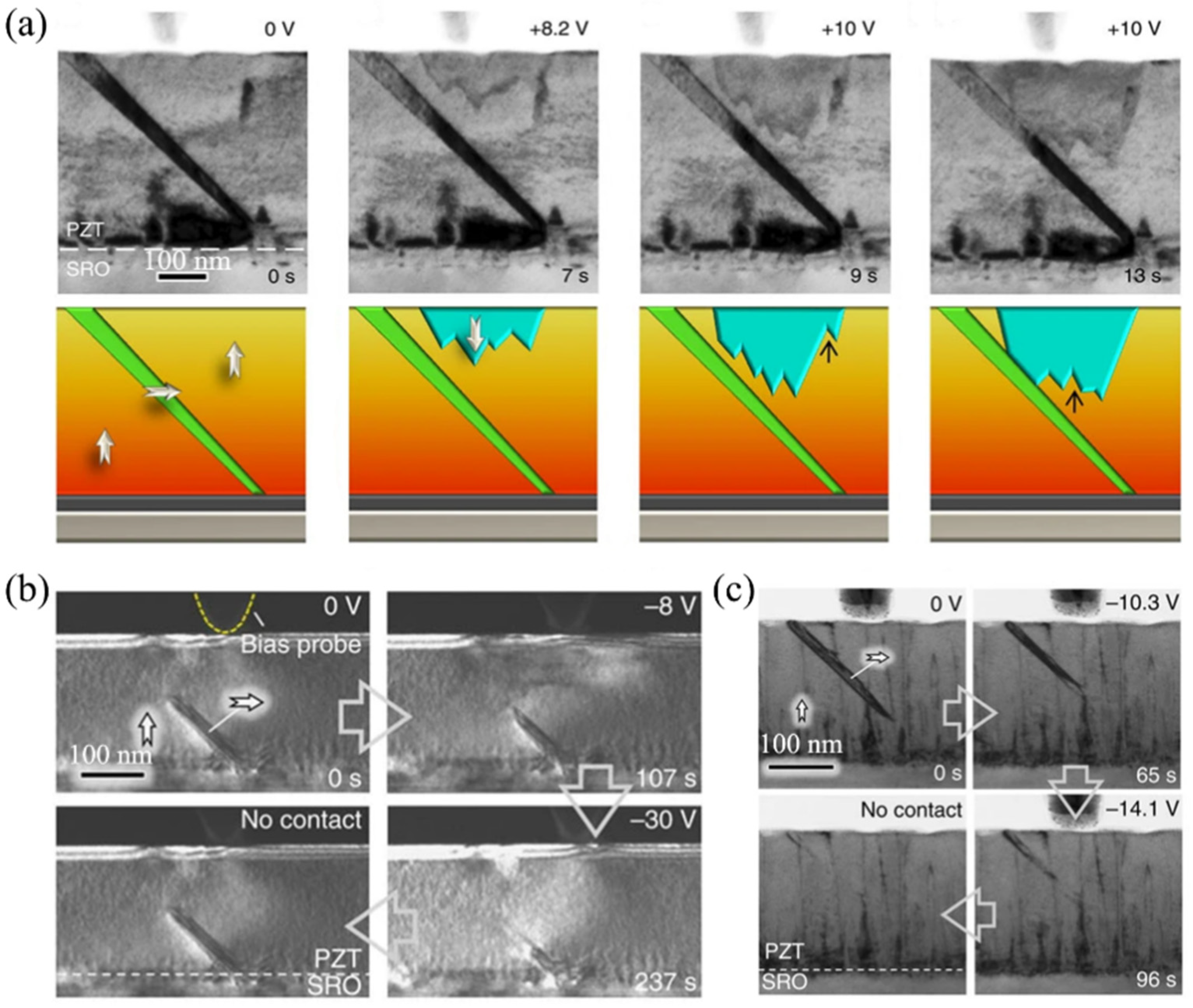
The external electric field applied along the out-of-plane direction is conducive to the formation of c-domains. Because the direction of the external stimuli is the same as the polarization direction inside c-domain in PTFs, the enthalpy of c-domain can be reduced. As a result, it is thermodynamically favorable to the formation of c-domains [143,144,145]. Figure 12a shows the formation of c-domain under the external electric field along the out-of-plane direction from 0 V to 8.2 V, and then propagates at 10 V [146].
Concurrently, the external electric field along the out-of-plane direction is detrimental to the formation of a-domain, and could even erase the existing one. Whether the a-domain could be erased completely depends on the mobility of domain walls. Figure 12b,c shows the domain evolution at different positions under the external electric field by in situ TEM [147]. Regardless of whether a-domain is at the film/substrate interface or at the free surface, as the applied electric field increases, the volume of the a-domain will decrease. However, the elastic energy cost of erasing the a-domain at the interface between PTFs and the substrate is relatively high. Domain walls here are difficult to migrate, and it is difficult to completely disappear even under a large external electric field. When the applied electric field is removed, the a-domain will return to its original state. On the contrary, a-domains at the free surface are not pinned and could migrate more easily. Under the external electric field, the a-domain almost disappears. After removing the electric field, the a-domain will not return to its original state. Therefore, the evolution of domain structures by the external electric field is related to the mobility of the domain structure itself.

4.2. Influence of External Mechanical Stress on Domain Structures

The effect of the external mechanical stress on the evolution of domain structures is similar to that of the misfit strain. Overall, the evolution of domain structures by the external mechanical stress is related to the direction of applied stress. The compressive stress along the out-of-plane direction is conducive to the formation of a-domains, while compressive stress along the in-plane direction is detrimental to the formation of a-domains [148,149]. Figure 13a shows the domain evolution under the external mechanical stress in the out-of-plane direction by in situ TEM [147]. It is demonstrated that external stimuli will conducive to the in-plane polarization and induce the growth of a-domains. The a-domain will grow to reach the free surface of the film and then widen. When the applied mechanical stress is removed, it will return to its original state. Slutsker et al. use the phase field simulation to analysis the domain structure evolution with the same condition, and the result is consistent with the experimental observation [150]. As shown in Figure 13b, for PTFs subjected to out-of-plane compressive stress, the fraction of c-domain is reduced continuously, and finally the three-domain state is transformed into the a1/a2-domain state.
On the contrary, applying compressive stress in the in-plane direction will conducive to the out-of-plane polarization and the a-domain fraction decreases until it eventually disappears. Figure 13c confirms that under the external compressive stress along the in-plane direction, a-domains shrink and eventually even disappear [147]. The phase field simulation results are shown in Figure 13d [151]. When compressive stress is applied along the in-plane direction, the a-domain fraction gradually decreases, and the c-domain fraction increases accordingly. The three domain state finally changes from hierarchical configuration to cellular configuration.

5. Summary and Prospects

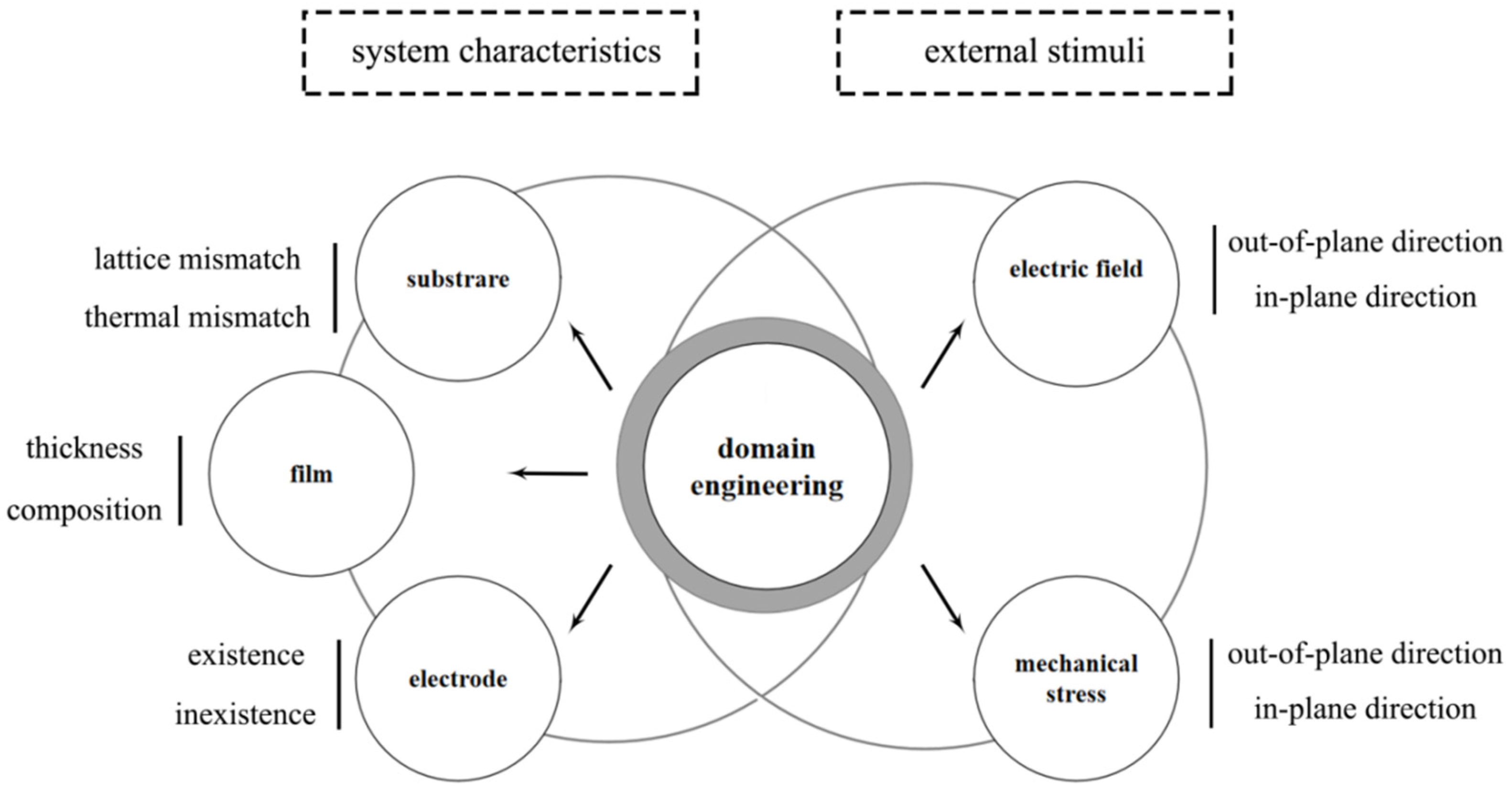
In this review, we reviewed growth mechanisms of vapor deposited PTFs. The energy accumulated during thin film growth can be released by variation of the growth modes, generation of misfit dislocations and formation of domain structures. We then reviewed the influential mechanisms of piezoelectric domains, ranging from substrate, film, and electrode characteristics, to external stimuli including electrical field and mechanical stress, as shown in Figure 14. We think this review could not only provide insights to understand domain structure-piezoelectric property relationship, but also motivate future experimental, theoretical and simulation studies on FS and FC domain engineering in PTFs.
Regarding the future prospects, controlling strain energies that are originated from substrate, seed layer, and electrode layer are important. Various research has emphasized designing different top electrode-nanolayer and bottom seed electrode-nanolayer in order to introduce unbalanced interface mismatch strains and then domain interfaces. This is known as domain patterning, where high-density of nanosized FS domains will lead to higher polarized sensitivity and piezoelectric constant. Unbalanced electrode design also provides the variety of PTFs for different MEMS applications. Moreover, with the development of TEM from ex situ to in situ observation and from conventional morphology to differential phase contrast analysis [152,153,154], domain interface structure and kinetics may be visualized. These studies are of great importance for understanding domain-wall kinetics and then domain evolution characteristics including volume fraction, shape, and density. FS domain interfaces can be categorized as terrace-defect interfaces (defined as coherent interface with terrace defect structure) with dislocation (b) and step height (h) characters. In order to maintain the interface coherency, the biaxial strains will generate near domain interface region and lead to formation of a new terrace plane with specific crystallographic orientation and leaving a misfit dislocation. Compared to metal interface with additional disclination (θ) character [155,156,157], terrace-defect domain interfaces in piezoelectric oxides are less complicated but require much more research on their effects to understand their crystallographic structure and motion kinetics in the future. Especially, in situ TEM experiments and simulations on motion kinetics of these domain interfaces are suggested in the future.

Author Contributions

Conceptualization, C.C., M.G. and Y.L.; original draft preparation, C.C., Q.Z. and Y.L.; acquisition, analysis and interpretation of data for the work, C.C., J.S. and Q.Z.; supervision, Y.L. and T.F. All authors have read and agreed to the published version of the manuscript.

Funding

This research was funded by the National Science Foundation of China (No. 51901129,52171144).

Institutional Review Board Statement

Not applicable.

Informed Consent Statement

Not applicable.

Data Availability Statement

Data sharing is not applicable.

Conflicts of Interest

The authors declare no conflict of interest.

References

  1. Chapman, D.W. Some thin-film properties of a new ferroelectric composition. J. Appl. Phys. 1969, 40, 2381–2385. [Google Scholar] [CrossRef]
  2. Khan, A.; Abas, Z.; Soo Kim, H.; Oh, I.K. Piezoelectric thin films: An integrated review of transducers and energy harvesting. Smart Mater. Struct. 2016, 25, 05032. [Google Scholar] [CrossRef]
  3. Arndt, R.E.A.; Paul, S.; Ellis, C.R. Application of Piezoelectric Film in Cavitation Research. J. Hydraul. Eng. 1997, 123, 539–548. [Google Scholar] [CrossRef]
  4. Francombe, M.H. Ferroelectric films and their device applications. Thin Solid Film. 1972, 13, 413–433. [Google Scholar] [CrossRef]
  5. Setter, N.; Damjanovic, D.; Eng, L.; Fox, G.; Gevorgian, S.; Hong, S.; Kingon, A.; Kohlstedt, H.; Park, N.Y.; Stephenson, G.B.; et al. Ferroelectric thin films: Review of materials, properties, and applications. J. Appl. Phys. 2006, 100, 51606. [Google Scholar] [CrossRef]
  6. Talin, A.A.; Smith, S.M.; Voight, S.; Finder, J.; Eisenbeiser, K.; Penunuri, D.; Yu, Z.; Fejes, P.; Eschrich, T.; Curless, J.; et al. Epitaxial PbZr0.52Ti0.48O3 films on SrTiO3/(001)Si subsubstrates deposited by sol-gel method. Appl. Phys. Lett. 2002, 81, 1062–1064. [Google Scholar] [CrossRef]
  7. Zhou, J.; Demiguel-Ramos, M.; Garcia-Gancedo, L.; Iborra, E.; Olivares, J.; Jin, H.; Luo, J.K.; Elhady, A.S.; Dong, S.R.; Wang, D.M.; et al. Characterisation of aluminium nitride films and surface acoustic wave devices for microfluidic applications. Sens. Actuators B Chem. 2014, 202, 984–992. [Google Scholar] [CrossRef]
  8. Scott, J.F. New developments on FRAMs: [3D] structures and all-perovskite FETs. Mater. Sci. Eng. B Solid-State Mater. Adv. Technol. 2005, 120, 6–12. [Google Scholar] [CrossRef]
  9. Kang, Y.S.; Fan, Q.; Xiao, B.; Alivov, Y.I.; Xie, J.; Onojima, N.; Cho, S.J.; Moon, Y.T.; Lee, H.; Johnstone, D.; et al. Fabrication and current-voltage characterization of a ferroelectric lead zirconate titanate/ AlGaN/GaN field effect transistor. Appl. Phys. Lett. 2006, 88, 338–383. [Google Scholar] [CrossRef]
  10. Ali, W.R.; Prasad, M. Piezoelectric MEMS based acoustic sensors: A review. Sens. Actuators A Phys. 2020, 301. [Google Scholar] [CrossRef]
  11. Noda, M.; Nomura, T.; Popovici, D.; Murakami, S.; Okuyama, M. A highly-sensitive Ba(Ti1−xSnx)O3 thin film dielectric bolometer for uncooled IR sensor. Integr. Ferroelectr. 2004, 63, 35–40. [Google Scholar] [CrossRef]
  12. Uchino, K. Ferroelectric Devices; Marcel Dekker: New York, NY, USA, 2018; ISBN 9781439803769. [Google Scholar]
  13. Thapliy, R.; Okano, Y.; Nakamura, S. Electrooptic characteristics of thin-film PLZT waveguide using ridge-type mach-Zehnder modulator. J. Light. Technol. 2003, 21, 1820–1827. [Google Scholar] [CrossRef]
  14. Qin, W.; Li, T.; Li, Y.; Qiu, J.; Ma, X.; Chen, X.; Hu, X.; Zhang, W. A high power ZnO thin film piezoelectric generator. Appl. Surf. Sci. 2016, 364, 670–675. [Google Scholar] [CrossRef]
  15. Sahu, M.; Hajra, S.; Lee, K.; Deepti, P.; Mistewicz, K.; Kim, H.J. Piezoelectric nanogenerator based on lead-free flexible pvdf-barium titanate composite films for driving low power electronics. Crystals 2021, 11, 85. [Google Scholar] [CrossRef]
  16. Miao, J.; Yuan, J.; Wu, H.; Yang, S.B.; Xu, B.; Cao, L.X.; Zhao, B.R. Crystal orientation dependence of the dielectric properties for epitaxial BaZr0.15Ti0.85O3 thin films. Appl. Phys. Lett. 2007, 90, 022903. [Google Scholar] [CrossRef]
  17. Ouyang, J.; Ramesh, R.; Roytburd, A.L. Theoretical Predictions for the Intrinsic Converse Longitudinal Piezoelectric Constants of Lead Zirconate Titanate Epitaxial Films. Adv. Eng. Mater. 2005, 7, 229–232. [Google Scholar] [CrossRef]
  18. Jin, L.; He, Z.; Damjanovic, D. Nanodomains in Fe3+-doped lead zirconate titanate ceramics at the morphotropic phase boundary do not correlate with high properties. Appl. Phys. Lett. 2009, 95, 2059–2421. [Google Scholar] [CrossRef] [Green Version]
  19. Li, Z.; Wang, Y.; Tang, Y.; Zhao, X.; Wang, T.; Duan, Z.; Wang, F.; Li, X.; Leung, C.M.; Fang, B. Growth and electrical properties of high-Curie point rhombohedral Mn-Pb(In1/2Nb1/2)O3-Pb(Mg1/3Nb2/3)O3-PbTiO3 thin films. J. Am. Ceram. Soc. 2021, 104, 313–321. [Google Scholar] [CrossRef]
  20. Jin, L.; Porokhonskyy, V.; Damjanovic, D. Domain wall contributions in Pb (Zr,Ti) O3 ceramics at morphotropic phase boundary: A study of dielectric dispersion. Appl. Phys. Lett. 2010, 96, 242902. [Google Scholar] [CrossRef] [Green Version]
  21. Sando, D.; Barthélémy, A.; Bibes, M. BiFeO3 epitaxial thin films and devices: Past, present and future. J. Phys. Condens. Matter 2014, 26, 473201. [Google Scholar] [CrossRef]
  22. Cao, Y.; Shen, J.; Randall, C.; Chen, L.Q. Effect of multi-domain structure on ionic transport, electrostatics, and current evolution in BaTiO3 ferroelectric capacitor. Acta Mater. 2016, 112, 224–230. [Google Scholar] [CrossRef] [Green Version]
  23. Lahoche, L.; Lorman, V.; Rochal, S.B.; Roelandt, J.M. Model of the plane laminar PbTiO3 thin film domain structure on MgO substrate. J. Appl. Phys. 2003, 93, 6238–6247. [Google Scholar] [CrossRef]
  24. Liu, H.; Chen, J.; Huang, H.; Fan, L.; Ren, Y.; Pan, Z.; Deng, J.; Chen, L.Q.; Xing, X. Role of Reversible Phase Transformation for Strong Piezoelectric Performance at the Morphotropic Phase Boundary. Phys. Rev. Lett. 2018, 120, 055501. [Google Scholar] [CrossRef] [PubMed] [Green Version]
  25. Nakashima, S.; Fujisawa, H.; Kobune, M.; Shimizu, M.; Kotaka, Y. Growth and local structure of BiFeO3 thin films with giant tetragonality on SrRuO3-buffered SrTiO3(001) substrate by ion beam sputtering. Jpn. J. Appl. Phys. 2014, 53, 05FE05. [Google Scholar] [CrossRef]
  26. Zhu, K.; Wu, S.; Song, B.; Ge, G.; Shi, Y.; Xu, L.; Yan, H.; Shen, B.; Zhai, J. Multi-domain BNiT modification enhanced the piezoelectric properties of BNT-based lead-free thin films. J. Mater. Chem. C 2020, 8, 17114–17121. [Google Scholar] [CrossRef]
  27. Kim, D.J.; Maria, J.P.; Kingon, A.I.; Streiffer, S.K. Evaluation of intrinsic and extrinsic contributions to the piezoelectric properties of Pb(Zr1-XTX)O3 thin films as a function of composition. J. Appl. Phys. 2003, 93, 5568–5575. [Google Scholar] [CrossRef]
  28. Ghosh, D.; Sakata, A.; Carter, J.; Thomas, P.A.; Han, H.; Nino, J.C.; Jones, J.L. Domain wall displacement is the origin of superior permittivity and piezoelectricity in BaTiO3 at intermediate grain sizes. Adv. Funct. Mater. 2014, 24, 885–896. [Google Scholar] [CrossRef] [Green Version]
  29. Trolier-McKinstry, S.; Gharb, N.B.; Damjanovic, D. Piezoelectric nonlinearity due to motion of 180° domain walls in ferroelectric materials at subcoercive fields: A dynamic poling model. Appl. Phys. Lett. 2006, 88, 1235–1788. [Google Scholar] [CrossRef]
  30. Roytburd, A.L.; Ouyang, J.; Artemev, A. Polydomain structures in ferroelectric and ferroelastic epitaxial films. J. Phys. Condens. Matter 2017, 29, 163001. [Google Scholar] [CrossRef]
  31. Ouyang, J.; Zhang, W.; Alpay, S.P.; Roytburd, A.L. Effect of elastic domains on electromechanical response of epitaxial ferroelectric films with a three-domain architecture. J. Adv. Ceram. 2013, 2, 1–10. [Google Scholar] [CrossRef] [Green Version]
  32. Bühlmann, S.; Dwir, B.; Baborowski, J.; Muralt, P. Size effect in mesoscopic epitaxial ferroelectric structures: Increase of piezoelectric response with decreasing feature size. Appl. Phys. Lett. 2002, 80, 3195–3197. [Google Scholar] [CrossRef]
  33. Wada, S.; Yako, K.; Kakemoto, H.; Tsurumi, T.; Kiguchi, T. Enhanced piezoelectric properties of barium titanate single crystals with different engineered-domain sizes. J. Appl. Phys. 2005, 98, L33. [Google Scholar] [CrossRef]
  34. Tan, Y.; Zhang, J.; Wang, C.; Viola, G.; Yan, H. Enhancement of electric field-induced strain in BaTiO3 ceramics through grain size optimization. Phys. Status Solidi Appl. Mater. Sci. 2015, 212, 433–438. [Google Scholar] [CrossRef]
  35. Feng, Y.; Tang, Y.; Ma, D.; Zhu, Y.; Zou, M.; Han, M.; Ma, J.; Ma, X. Thickness-Dependent Evolution of Piezoresponses and Stripe 90° Domains in (101)-Oriented Ferroelectric PbTiO3 Thin Films. ACS Appl. Mater. Interfaces 2018, 10, 24627–24637. [Google Scholar] [CrossRef] [PubMed]
  36. Feng, Y.P.; Tang, Y.L.; Zhu, Y.L.; Zou, M.J.; Wang, Y.J.; Ma, X.L. Thickness-dependent evolution of piezoresponses and a/c domains in [101]-oriented PbTiO3 ferroelectric films. J. Appl. Phys. 2020, 128, 224102. [Google Scholar] [CrossRef]
  37. Nagarajan, V.; Roytburd, A.; Stanishevsky, A.; Prasertchoung, S.; Zhao, T.; Chen, L.; Melngailis, J.; Auciello, O.; Ramesh, R. Dynamics of ferroelastic domains in ferroelectric thin films. Nat. Mater. 2003, 2, 43–47. [Google Scholar] [CrossRef]
  38. Li, S.; Bhalla, A.S.; Newnham, R.E.; Cross, L.E. Quantitative evaluation of extrinsic contribution to piezoelectric coefficient d33 in ferroelectric PZT ceramics. Mater. Lett. 1993, 17, 21–26. [Google Scholar] [CrossRef]
  39. Li, J.H.; Chen, L.; Nagarajan, V.; Ramesh, R.; Roytburd, A.L. Finite element modeling of piezoresponse in nanostructured ferroelectric films. Appl. Phys. Lett. 2004, 84, 2626–2628. [Google Scholar] [CrossRef]
  40. Pramanick, A.; Damjanovic, D.; Daniels, J.E.; Nino, J.C.; Jones, J.L. Origins of electro-mechanical coupling in polycrystalline ferroelectrics during subcoercive electrical loading. J. Am. Ceram. Soc. 2011, 94, 293–309. [Google Scholar] [CrossRef]
  41. Freund, L.B.; Suresh, S. Thin Film Materials: Stress, Defect Formation and Surface Evolution; Cambridge University Press: Cambridge, UK, 2003; ISBN 9780511165658. [Google Scholar]
  42. Ma, Y.; Song, J.; Wang, X.; Liu, Y.; Zhou, J. Synthesis, microstructure and properties of magnetron sputtered lead zirconate titanate (Pzt) thin film coatings. Coatings 2021, 11, 944. [Google Scholar] [CrossRef]
  43. Yu, K.Y.; Chen, Y.; Li, J.; Liu, Y.; Wang, H.; Kirk, M.A.; Li, M.; Zhang, X. Measurement of Heavy Ion Irradiation Induced In-Plane Strain in Patterned Face-Centered-Cubic Metal Films: An In Situ Study. Nano Lett. 2016, 16, 7481–7489. [Google Scholar] [CrossRef] [PubMed]
  44. Hassan, M.M. Antimicrobial Coatings for Textiles. In Handbook of Antimicrobial Coatings; Elsevier: Amsterdam, The Netherlands, 2017; ISBN 9780128119822. [Google Scholar]
  45. Cranston, R.R.; Lessard, B.H. Metal phthalocyanines: Thin-film formation, microstructure, and physical properties. RSC Adv. 2021, 11, 21716–21737. [Google Scholar] [CrossRef]
  46. Martin, L.W.; Chu, Y.H.; Ramesh, R. Advances in the growth and characterization of magnetic, ferroelectric, and multiferroic oxide thin films. Mater. Sci. Eng. R Reports 2010, 68, 89–133. [Google Scholar] [CrossRef] [Green Version]
  47. Yeo, H.G.; Xue, T.; Roundy, S.; Ma, X.; Rahn, C.; Trolier-McKinstry, S. Strongly (001) Oriented Bimorph PZT Film on Metal Foils Grown by rf-Sputtering for Wrist-Worn Piezoelectric Energy Harvesters. Adv. Funct. Mater. 2018, 28, 1801327. [Google Scholar] [CrossRef]
  48. Dahotre, N.B. Surface morphology of crystalline materials. Mater. Manuf. Process. 1992, 7, 675–677. [Google Scholar] [CrossRef]
  49. Claeys, C.; Simoen, E. Extended Defects in Germanium: Fundamental and Technological Aspects; Springer: New York, NY, USA, 2009; ISBN 9783540856146. [Google Scholar]
  50. Rijnders, G.; Blank, D.H.A. Pulsed Laser Deposition of Thin Films: Applications-Led Growth of Functional Materials; Wiley Online Books: Hoboken, NJ, USA, 2006; pp. 177–190. ISBN 9780471447092. [Google Scholar]
  51. Ohring, M. The Materials Science of Thin Films; Academic Press: San Diego, CA, USA, 1992; ISBN 012524990X. [Google Scholar]
  52. Tan, S.; Lam, P.M. Monte carlo simulation of three-dimensional islands. Phys. Rev. B 1999, 60, 8314–8320. [Google Scholar] [CrossRef]
  53. Nagarajan, V.; Jia, C.L.; Kohlstedt, H.; Waser, R.; Misirlioglu, I.B.; Alpay, S.P.; Ramesh, R. Misfit dislocations in nanoscale ferroelectric heterostructures. Appl. Phys. Lett. 2005, 86, 1–3. [Google Scholar] [CrossRef] [Green Version]
  54. Goh, W.C.; Xu, S.Y.; Wang, S.J.; Ong, C.K. Microstructure and growth mode at early growth stage of laser-ablated epitaxial Pb(Zr0.52Ti0.48)O3 films on a SrTiO3 substrate. J. Appl. Phys. 2001, 89, 4497–4502. [Google Scholar] [CrossRef]
  55. Yoneda, Y.; Okabe, T.; Sakaue, K.; Terauchi, H. Growth of ultrathin BaTiO3 films on SrTiO3 and MgO substrates. Surf. Sci. 1998, 410, 62–69. [Google Scholar] [CrossRef]
  56. Tabata, H.; Tanaka, H.; Kawai, T. Formation of artificial BaTiO3/SrTiO3 superlattices using pulsed laser deposition and their dielectric properties. Appl. Phys. Lett. 1994, 65, 1970–1972. [Google Scholar] [CrossRef]
  57. Norton, M.G.; Scarfone, C.; Li, J.; Carter, C.B.; Mayer, J.W. Epitaxy of barium titanate thin films grown on MgO by pulsed-laser ablation. J. Mater. Res. 1991, 6, 2022–2025. [Google Scholar] [CrossRef]
  58. Sreenivas, K.; Sayer, M.; Garrett, P. Properties of D.C. magnetron-sputtered lead zirconate titanate thin films. Thin Solid Film. 1989, 172, 251–267. [Google Scholar] [CrossRef]
  59. Simon, W.K.; Akdogan, E.K.; Safari, A. Anisotropic strain relaxation in (Ba0.6Sr0.4)TiO3 epitaxial thin films. J. Appl. Phys. 2005, 97. [Google Scholar] [CrossRef]
  60. Breckenfeld, E.; Shah, A.B.; Martin, L.W. Strain evolution in non-stoichiometric heteroepitaxial thin-film perovskites. J. Mater. Chem. C 2013, 1, 8052–8059. [Google Scholar] [CrossRef] [Green Version]
  61. Wakiya, N.; Kuroyanagi, K.; Xuan, Y.; Shinozaki, K.; Mizutani, N. Nucleation and growth behavior of epitaxial Pb(Zr,Ti)O3/MgO(100) observed by atomic force microscopy. Thin Solid Film. 1999, 357, 166–172. [Google Scholar] [CrossRef]
  62. Visinoiu, A.; Alexe, M.; Lee, H.N.; Zakharov, D.N.; Pignolet, A.; Hesse, D.; Gösele, U. Initial growth stages of epitaxial BaTiO3 films on vicinal SrTiO3 (001) substrate surfaces. J. Appl. Phys. 2002, 91, 10157–10162. [Google Scholar] [CrossRef]
  63. Kang, Y.S.; Tanaka, I.; Adachi, H.; Park, S.J. Growth mechanism of BaTiO3 thin film by theoretical calculation of electronic structure. Jpn. J. Appl. Physics Part 2 Lett. 1996, 35, L1614–L1617. [Google Scholar] [CrossRef]
  64. Shin, J.; Kalinin, S.V.; Borisevich, A.Y.; Plummer, E.W.; Baddorf, A.P. Layer-by-layer and pseudo-two-dimensional growth modes for heteroepitaxial BaTiO3 films by exploiting kinetic limitations. Appl. Phys. Lett. 2007, 91, 1005. [Google Scholar] [CrossRef]
  65. Jesson, D.E.; Chen, K.M.; Pennycook, S.J. Kinetic pathways to strain relaxation in the Si-Ge system. MRS Bull. 1996, 21, 31–37. [Google Scholar] [CrossRef]
  66. Zhang, D.; Guan, L.; Li, Z.; Pan, G.; Tan, X.; Li, L. Simulation of island aggregation influenced by substrate temperature, incidence kinetic energy and intensity in pulsed laser deposition. Appl. Surf. Sci. 2006, 253, 874–880. [Google Scholar] [CrossRef]
  67. Lee, J.Y.; Juang, J.Y.; Wu, K.H.; Uen, T.M.; Gou, Y.S. Annealing characteristics of pulsed laser deposited homoepitaxial SrTiO3 thin films. Surf. Sci. 2001, 488, 277–285. [Google Scholar] [CrossRef]
  68. Kim, D.H.; Kwok, H.S. Pulsed laser deposition of BaTiO3 thin films and their optical properties. Appl. Phys. Lett. 1995, 67, 1803. [Google Scholar] [CrossRef]
  69. Blank, D.H.A.; Koster, G.; Rijnders, G.; Van Setten, E.; Slycke, P.; Rogalla, H. Imposed layer-by-layer growth by pulsed laser interval deposition. Appl. Phys. A Mater. Sci. Process. 1999, 69, S17–S22. [Google Scholar] [CrossRef]
  70. He, F.; Wells, B.O. Lattice strain in epitaxial BaTiO3 thin films. Appl. Phys. Lett. 2006, 88, 152908. [Google Scholar] [CrossRef] [Green Version]
  71. Song, J.H.; Jeong, Y.H. SrTiO3 homoepitaxy by the pulsed laser deposition method: Island, layer-by-layer, and step-flow growth. Solid State Commun. 2003, 125, 563–566. [Google Scholar] [CrossRef]
  72. Kang, H.-S.; Lee, W.-J. Effects of deposition temperature and seed layer on the optical properties of lead zirconate titanate films. J. Vac. Sci. Technol. A Vac. Surf. Film. 2002, 20, 1498–1504. [Google Scholar] [CrossRef]
  73. Hiltunen, J.; Seneviratne, D.; Tuller, H.L.; Lappalainen, J.; Lantto, V. Crystallographic and dielectric properties of highly oriented BaTiO3 films: Influence of oxygen pressure utilized during pulsed laser deposition. J. Electroceramics 2009, 22, 395–404. [Google Scholar] [CrossRef]
  74. Chen, A.P.; Khatkhatay, F.; Zhang, W.; Jacob, C.; Jiao, L.; Wang, H. Strong oxygen pressure dependence of ferroelectricity in BaTiO3/SrRuO3/SrTiO3 epitaxial heterostructures. J. Appl. Phys. 2013, 114, 1–6. [Google Scholar] [CrossRef]
  75. Groenen, R.; Smit, J.; Orsel, K.; Vailionis, A.; Bastiaens, B.; Huijben, M.; Boller, K.; Rijnders, G.; Koster, G. Research Update: Stoichiometry controlled oxide thin film growth by pulsed laser deposition. APL Mater. 2015, 3, 70701. [Google Scholar] [CrossRef]
  76. Liu, Y.; Bufford, D.; Wang, H.; Sun, C.; Zhang, X. Mechanical properties of highly textured Cu/Ni multilayers. Acta Mater. 2011, 59, 1924–1933. [Google Scholar] [CrossRef]
  77. Liu, Y.; Karaman, I.; Wang, H.; Zhang, X. Two types of martensitic phase transformations in magnetic shape memory alloys by in-situ nanoindentation studies. Adv. Mater. 2014, 26, 3893–3898. [Google Scholar] [CrossRef]
  78. Fan, Z.; Liu, Y.; Xue, S.; Rahimi, R.M.; Bahr, D.F.; Wang, H.; Zhang, X. Layer thickness dependent strain rate sensitivity of Cu/amorphous CuNb multilayer. Appl. Phys. Lett. 2017, 110, 611. [Google Scholar] [CrossRef] [Green Version]
  79. Feigl, L.; Yudin, P.; Stolichnov, I.; Sluka, T.; Shapovalov, K.; Mtebwa, M.; Sandu, C.S.; Wei, X.K.; Tagantsev, A.K.; Setter, N. Controlled stripes of ultrafine ferroelectric domains. Nat. Commun. 2014, 5, 4677. [Google Scholar] [CrossRef] [Green Version]
  80. Emelyanov, A.Y.; Pertsev, N.A. Abrupt changes and hysteretic behavior of 90° domains in epitaxial ferroelectric thin films with misfit dislocations. Phys. Rev. B 2003, 68, 214103. [Google Scholar] [CrossRef]
  81. Chu, M.W.; Szafraniak, I.; Scholz, R.; Harnagea, C.; Hesse, D.; Alexe, M.; Gösele, U. Impact of misfit dislocation on the polarization instability of epitaxial nanostructured ferroelectric perovskites. Nat. Mater. 2004, 3, 87–90. [Google Scholar] [CrossRef]
  82. Misirlioglu, I.B.; Vasiliev, A.L.; Alpay, S.P.; Aindow, M.; Ramesh, R. Defect microstructures in epitaxial PbZr0.2Ti 0.8O3 films grown on (001) SrTiO3 by pulsed laser deposition. J. Mater. Sci. 2006, 41, 697–707. [Google Scholar] [CrossRef]
  83. Qiu, Q.Y.; Mahjoub, R.; Alpay, S.P.; Nagarajan, V. Misfit strain-film thickness phase diagrams and related electromechanical properties of epitaxial ultra-thin lead zirconate titanate films. Acta Mater. 2010, 58, 823–835. [Google Scholar] [CrossRef]
  84. Jesson, D.E.; Pennycook, S.J.; Baribeau, J.M. Direct imaging of interfacial ordering in ultrathin (SimGen)p superlattices. Phys. Rev. Lett. 1991, 66, 750–753. [Google Scholar] [CrossRef] [PubMed]
  85. Fujisawa, T.; Nakaki, H.; Ikariyama, R.; Morioka, H.; Yamada, T.; Saito, K.; Funakubo, H. Thick epitaxial Pb(Zr0.35,Ti0.65)O3 films grown on (100)CaF2 substrates with polar-axis-orientation. Appl. Phys. Express 2008, 1, 0850011–0850013. [Google Scholar] [CrossRef]
  86. Jain, S.C.; Harker, A.H.; Cowley, R.A. Misfit strain and misfit dislocations in lattice mismatched epitaxial layers and other systems. Philos. Mag. A Phys. Condens. Matter Struct. Defects Mech. Prop. 1997, 75, 1461–1515. [Google Scholar] [CrossRef]
  87. Liu, Y.; Bufford, D.; Rios, S.; Wang, H.; Chen, J.; Zhang, J.Y.; Zhang, X. A formation mechanism for ultra-thin nanotwins in highly textured Cu/Ni multilayers. J. Appl. Phys. 2012, 111, 118. [Google Scholar] [CrossRef]
  88. Johnson-Wilke, R.L.; Tinberg, D.S.; Yeager, C.; Qu, W.; Fong, D.D.; Fister, T.T.; Streiffer, S.K.; Han, Y.; Reaney, I.M.; Trolier-Mckinstry, S. Coherently strained epitaxial Pb(Zr1-xTix)O3 thin films. J. Appl. Phys. 2013, 114, 164104. [Google Scholar] [CrossRef] [Green Version]
  89. Liu, Y.; Chen, Y.; Yu, K.Y.; Wang, H.; Chen, J.; Zhang, X. Stacking fault and partial dislocation dominated strengthening mechanisms in highly textured Cu/Co multilayers. Int. J. Plast. 2013, 49, 152–163. [Google Scholar] [CrossRef]
  90. Liu, Y.; Yang, K.M.; Hay, J.; Fu, E.G.; Zhang, X. The effect of coherent interface on strain-rate sensitivity of highly textured Cu/Ni and Cu/V multilayers. Scr. Mater. 2019, 162, 33–37. [Google Scholar] [CrossRef]
  91. Matthews, J.W.; Jesser, W.A. Experimental evidence for pseudomorphic growth of platinum on gold. Acta Metall. 1967, 15, 595–600. [Google Scholar] [CrossRef]
  92. Stemmer, S.; Streiffer, S.K.; Ernst, F.; Rühle, M. Dislocations in PbTiOSrTiO3 homoepitaxy by the pulsed laser deposition method: Island, layer-by-layer, and step-flow growth Thin Films. Phys. Status Solidi 1995, 147, 135–154. [Google Scholar] [CrossRef]
  93. Freund, L.B. The stability of a dislocation threading a strained layer on a substrate. J. Appl. Mech. Trans. ASME 1987, 54, 553–557. [Google Scholar] [CrossRef]
  94. Matthews, J.W. Defects Associated With the Accommodation of Misfit Between Crystals. J. Vac. Sci. Technol. 1974, 12, 126–133. [Google Scholar] [CrossRef]
  95. Matthews, J.W.; Blakeslee, A.E. Defects in epitaxial multilayers: I. Misfit dislocations. J. Cryst. Growth 1974, 27, 118–125. [Google Scholar] [CrossRef]
  96. Shao, S.; Akasheh, F.; Wang, J.; Liu, Y. Alternative misfit dislocations pattern in semi-coherent FCC {100} interfaces. Acta Mater. 2018, 144, 177–186. [Google Scholar] [CrossRef]
  97. Wunderlich, W.; Fujimoto, M.; Ohsato, H. Molecular dynamics calculations about misfit dislocations at the BaTiO3/SrTiO3-interface. Thin Solid Film. 2000, 375, 9–14. [Google Scholar] [CrossRef]
  98. Little, S.; Zangwill, A. Equilibrium microstructure of epitaxial thin films. Phys. Rev. B 1994, 49, 16659–16669. [Google Scholar] [CrossRef] [PubMed]
  99. Feng, Y.; Tang, Y.; Zhu, Y.; Zou, M.; Ma, X. Misfit strain relaxations of (101)-oriented ferroelectric PbTiO3/(La,Sr)(Al, Ta)O3 thin film systems. J. Mater. Res. 2018, 33, 4156–4164. [Google Scholar] [CrossRef]
  100. Tang, Y.L.; Zhu, Y.L.; Liu, Y.; Wang, Y.J.; Ma, X.L. Giant linear strain gradient with extremely low elastic energy in a perovskite nanostructure array. Nat. Commun. 2017, 8, 15994. [Google Scholar] [CrossRef] [Green Version]
  101. Peng, L.S.J.; Xi, X.X.; Moeckly, B.H.; Alpay, S.P. Strain relaxation during in situ growth of SrTiO3 thin films. Appl. Phys. Lett. 2003, 83, 4592–4594. [Google Scholar] [CrossRef] [Green Version]
  102. Alpay, S.P.; Roytburd, A.L. Equilibrium domain structures of epitaxial perovskite ferroelectric films. Mater. Res. Soc. Symp.-Proc. 1997, 477, 407–412. [Google Scholar] [CrossRef]
  103. Alpay, S.P.; Prakash, A.S.; Aggarwal, S.; Shuk, P.; Greenblatt, M.; Ramesh, R.; Roytburd, A.L. Polydomain formation in epitaxial PbTiO3 films. Scr. Mater. 1998, 39, 1435–1441. [Google Scholar] [CrossRef]
  104. Speck, J.S.; Pompe, W. Domain configurations due to multiple misfit relaxation mechanisms in epitaxial ferroelectric thin films. I. Theory. J. Appl. Phys. 1994, 76, 466–476. [Google Scholar] [CrossRef]
  105. Alpay, S.P.; Roytburd, A.L.; Nagarajan, V.; Bendersky, L.A.; Ramesh, R. Cellular domain architecture of stress-free epitaxial ferroelectric films. Mater. Res. Soc. Symp.-Proc. 2001, 655, 431–436. [Google Scholar] [CrossRef]
  106. Roitburd, A.L. Equilibrium structure of epitaxial layers. Phys. Status Solidi 1976, 37, 329–339. [Google Scholar] [CrossRef]
  107. Tagantsev, A.K.; Cross, L.E.; Fousek, J. Domains in Ferroic Crystals and Thin Films; Springer: New York, NY, USA, 2010; ISBN 9781441914163. [Google Scholar]
  108. Lee, K.S.; Choi, J.H.; Lee, J.Y.; Baik, S. Domain formation in epitaxial Pb(Zr,Ti)O3 thin films. J. Appl. Phys. 2001, 90, 4095–4102. [Google Scholar] [CrossRef] [Green Version]
  109. Zhang, W.; Yuan, M.; Wang, X.; Pan, W.; Wang, C.M.; Ouyang, J. Design and preparation of stress-free epitaxial BaTiO3 polydomain films by RF magnetron sputtering. Sci. Technol. Adv. Mater. 2012, 13, 35006. [Google Scholar] [CrossRef]
  110. Li, Y.L.; Hu, S.Y.; Liu, Z.K.; Chen, L.Q. Effect of substrate constraint on the stability and evolution of ferroelectric domain structures in thin films. Acta Mater. 2002, 50, 395–411. [Google Scholar] [CrossRef]
  111. Li, S.; Zhu, Y.L.; Tang, Y.L.; Liu, Y.; Zhang, S.R.; Wang, Y.J.; Ma, X.L. Thickness-dependent a1/a2 domain evolution in ferroelectric PbTiO3 films. Acta Mater. 2017, 131, 123–130. [Google Scholar] [CrossRef]
  112. Li, Y.L.; Chen, L.Q. Temperature-strain phase diagram for BaTiO3 thin films. Appl. Phys. Lett. 2006, 88, 072905. [Google Scholar] [CrossRef] [Green Version]
  113. Ehara, Y.; Nakashima, T.; Ichinose, D.; Shimizu, T.; Yamada, T.; Nishida, K.; Funakubo, H. Temperature dependence on the domain structure of epitaxial PbTiO3 films grown on single crystal substrates with different lattice parameters. Jpn. J. Appl. Phys. 2020, 59. [Google Scholar] [CrossRef]
  114. Damodaran, A.R.; Pandya, S.; Agar, J.C.; Cao, Y.; Vasudevan, R.K.; Xu, R.; Saremi, S.; Li, Q.; Kim, J.; McCarter, M.R.; et al. Three-State Ferroelastic Switching and Large Electromechanical Responses in PbTiO3 Thin Films. Adv. Mater. 2017, 29, 1702069. [Google Scholar] [CrossRef] [Green Version]
  115. Hamedi, L.; Guilloux-Viry, M.; Perrin, A.; Garry, G. Heteroepitaxial growth of PZT thin films on LiF substrate by pulsed laser deposition. Thin Solid Film. 1999, 352, 66–72. [Google Scholar] [CrossRef]
  116. Srikant, V.; Tarsa, E.J.; Clarke, D.R.; Speck, J.S. Crystallographic orientation of epitaxial BaTiO3 films: The role of thermal-expansion mismatch with the substrate. J. Appl. Phys. 1995, 77, 1517–1522. [Google Scholar] [CrossRef]
  117. Ogawa, T.; Senda, A.; Kasanami, T. Controlling the crystal orientations of lead titanate thin films. Jpn. J. Appl. Phys. 1991, 30, 2145–2148. [Google Scholar] [CrossRef]
  118. Kwak, B.S.; Erbil, A.; Budai, J.D.; Chisholm, M.F.; Boatner, L.A.; Wilkens, B.J. Domain formation and strain relaxation in epitaxial ferroelectric heterostructures. Phys. Rev. B 1994, 49, 14865–14879. [Google Scholar] [CrossRef] [PubMed]
  119. Lee, K.S.; Kang, Y.M.; Baik, S. Determination of domain structure and abundance of epitaxial Pb(Zr, Ti)O3 thin films grown on MgO(001) by rf magnetron sputtering. J. Mater. Res. 1999, 14, 132–141. [Google Scholar] [CrossRef]
  120. Kukhar, V.G.; Pertsev, N.A.; Kohlstedt, H.; Waser, R. Polarization states of polydomain epitaxial Pb (Zr1-xTix) O3 thin films and their dielectric properties. Phys. Rev. B 2006, 73. [Google Scholar] [CrossRef] [Green Version]
  121. Lee, K.S.; Kang, Y.M.; Baik, S. Domain structure of epitaxial PZT thin films grown on MgO(001) by RF magnetron sputtering. Integr. Ferroelectr. 1997, 14, 43–49. [Google Scholar] [CrossRef]
  122. Shannon, R.D.; Prewitt, C.T. Effective ionic radii in oxides and fluorides. Acta Crystallogr. Sect. B Struct. Crystallogr. Cryst. Chem. 1969, 25, 925–946. [Google Scholar] [CrossRef]
  123. Ichinose, D.; Nakashima, T.; Ehara, Y.; Oikawa, T.; Shimizu, T.; Sakata, O.; Yamada, T.; Funakubo, H. Orientation control of epitaxial tetragonal Pb(ZrxTi1-x)O3 thin films grown on (100)KTaO3 substrates by tuning the Zr/(Zr+Ti) ratio. Appl. Phys. Lett. 2015, 107. [Google Scholar] [CrossRef]
  124. Lee, K.; Lee, K.S.; Baik, S. Finite element analysis of domain structures in epitaxial PbTiO3 thin films. J. Appl. Phys. 2001, 90, 6327–6331. [Google Scholar] [CrossRef]
  125. Wang, J.; Zhang, T.Y. Effect of long-range elastic interactions on the toroidal moment of polarization in a ferroelectric nanoparticle. Appl. Phys. Lett. 2006, 88, 2340. [Google Scholar] [CrossRef]
  126. Zhou, Z.D.; Wu, D.Y. Domain structures of ferroelectric films under different electrical boundary conditions. AIP Adv. 2015, 5, 107206. [Google Scholar] [CrossRef] [Green Version]
  127. Sai, N.; Kolpak, A.M.; Rappe, A.M. Ferroelectricity in ultrathin perovskite films. Phys. Rev. B 2005, 72, 20101. [Google Scholar] [CrossRef] [Green Version]
  128. Junquera, J.; Ghosez, P. Critical thickness for ferroelectricity in perovskite ultrathin films. Nature 2003, 422, 506–509. [Google Scholar] [CrossRef] [PubMed]
  129. Dawber, M.; Chandra, P.; Littlewood, P.B.; Scott, J.F. Depolarization corrections to the coercive field in thin-film ferroelectrics. J. Phys. Condens. Matter 2003, 15, L393. [Google Scholar] [CrossRef]
  130. Prosandeev, S.; Bellaiche, L. Asymmetric screening of the depolarizing field in a ferroelectric thin film. Phys. Rev. B 2007, 75, 172109. [Google Scholar] [CrossRef]
  131. Kim, Y.K.; Kim, S.S.; Shin, H.; Baik, S. Thickness effect of ferroelectric domain switching in epitaxial PbTiO3 thin films on Pt(001)/MgO(001). Appl. Phys. Lett. 2004, 84, 5085–5087. [Google Scholar] [CrossRef]
  132. Kim, Y.K.; Lee, K.; Baik, S. Domain structure of epitaxial PbTiO3 thin films on Pt(001)/MgO(001) substrates. J. Appl. Phys. 2004, 95, 236–240. [Google Scholar] [CrossRef] [Green Version]
  133. Alpay, S.P.; Nagarajan, V.; Bendersky, L.A.; Vaudin, M.D.; Aggarwal, S.; Ramesh, R.; Roytburd, A.L. Effect of the electrode layer on the polydomain structure of epitaxial PbZr0.2Ti0.8O3 thin films. J. Appl. Phys. 1999, 85, 3271–3277. [Google Scholar] [CrossRef] [Green Version]
  134. Nelson, C.T.; Winchester, B.; Zhang, Y.; Kim, S.J.; Melville, A.; Adamo, C.; Folkman, C.M.; Baek, S.H.; Eom, C.B.; Schlom, D.G.; et al. Spontaneous vortex nanodomain arrays at ferroelectric heterointerfaces. Nano Lett. 2011, 11, 828–834. [Google Scholar] [CrossRef]
  135. Streiffer, S.K.; Eastman, J.A.; Fong, D.D.; Thompson, C.; Munkholm, A.; Ramana Murty, M.V.; Auciello, O.; Bai, G.R.; Stephenson, G.B. Observation of nanoscale 180° stripe domains in ferroelectric PbTiO3 thin films. Phys. Rev. Lett. 2002, 89, 67601. [Google Scholar] [CrossRef]
  136. Stephenson, G.B.; Elder, K.R. Theory for equilibrium 180° stripe domains in PbTiO3 films. J. Appl. Phys. 2006, 100, 55. [Google Scholar] [CrossRef]
  137. Damjanovic, D. Ferroelectric, dielectric and piezoelectric properties of ferroelectric thin films and ceramics. Rep. Prog. Phys. 1998, 61, 1267–1324. [Google Scholar] [CrossRef] [Green Version]
  138. Lu, W.; Fang, D.N.; Li, C.Q.; Hwang, K.C. Nonlinear electric-mechanical behavior and micromechanics modelling of ferroelectric domain evolution. Acta Mater. 1999, 47, 2913–2926. [Google Scholar] [CrossRef]
  139. Lu, H.; Bark, C.W.; Esque De Los Ojos, D.; Alcala, J.; Eom, C.B.; Catalan, G.; Gruverman, A. Mechanical writing of ferroelectric polarization. Science 2012, 335, 59–61. [Google Scholar] [CrossRef] [PubMed] [Green Version]
  140. Li, M.; Wang, B.; Liu, H.J.; Huang, Y.L.; Zhang, J.; Ma, X.; Liu, K.; Yu, D.; Chu, Y.H.; Chen, L.Q.; et al. Direct observation of weakened interface clamping effect enabled ferroelastic domain switching. Acta Mater. 2019, 171, 184–189. [Google Scholar] [CrossRef]
  141. Quandt, E.; Holleck, H. Materials development for thin film actuators. Microsyst. Technol. 1995, 1, 178–184. [Google Scholar] [CrossRef]
  142. Yin, Y.; Ye, H.; Zhan, W.; Hong, L.; Ma, H.; Xu, J. Preparation and characterization of unimorph actuators based on piezoelectric Pb(Zr0.52Ti0.48)O3 materials. Sens. Actuators A Phys. 2011, 171, 332–339. [Google Scholar] [CrossRef]
  143. Feigl, L.; McGilly, L.J.; Sandu, C.S.; Setter, N. Compliant ferroelastic domains in epitaxial Pb(Zr,Ti)O3 thin films. Appl. Phys. Lett. 2014, 104, 7. [Google Scholar] [CrossRef]
  144. Kohli, M.; Muralt, P.; Setter, N. Removal of 90° domain pinning in (100)Pb(Zr0.15Ti0.85)O3 thin films by pulsed operation. Appl. Phys. Lett. 1998, 72, 3217–3219. [Google Scholar] [CrossRef]
  145. Pertsev, N.A.; Emelyanov, A.Y. Domain-wall contribution to the piezoelectric response of epitaxial ferroelectric thin films. Appl. Phys. Lett. 1997, 71, 3646–3648. [Google Scholar] [CrossRef]
  146. Gao, P.; Britson, J.; Jokisaari, J.R.; Nelson, C.T.; Baek, S.H.; Wang, Y.; Eom, C.B.; Chen, L.Q.; Pan, X. Atomic-scale mechanisms of ferroelastic domain-wall-mediated ferroelectric switching. Nat. Commun. 2013, 4, 3791. [Google Scholar] [CrossRef] [Green Version]
  147. Gao, P.; Britson, J.; Nelson, C.T.; Jokisaari, J.R.; Duan, C.; Trassin, M.; Baek, S.H.; Guo, H.; Li, L.; Wang, Y.; et al. Ferroelastic domain switching dynamics under electrical and mechanical excitations. Nat. Commun. 2014, 5. [Google Scholar] [CrossRef] [PubMed] [Green Version]
  148. Alpay, S.P.; Ramesh, R.; Roytburd, A.L. Effect of uniaxial stress fields on the domain selection of epitaxial ferroelectric films. Ferroelectrics 1999, 221, 245–250. [Google Scholar] [CrossRef]
  149. Lu, X.; Chen, Z.; Cao, Y.; Tang, Y.; Xu, R.; Saremi, S.; Zhang, Z.; You, L.; Dong, Y.; Das, S.; et al. Mechanical-force-induced non-local collective ferroelastic switching in epitaxial lead-titanate thin films. Nat. Commun. 2019, 10, 3951. [Google Scholar] [CrossRef] [Green Version]
  150. Slutsker, J. Elastic Domain Architectures in Constrained Layers. AIP Conf. Proc. 2003, 626, 266–276. [Google Scholar] [CrossRef]
  151. Slutsker, J.; Artemev, A.; Roytburd, A.L. Morphological transitions of elastic domain structures in constrained layers. J. Appl. Phys. 2002, 91, 9049–9058. [Google Scholar] [CrossRef]
  152. Bufford, D.; Liu, Y.; Wang, J.; Wang, H.; Zhang, X. In situ nanoindentation study on plasticity and work hardening in aluminium with incoherent twin boundaries. Nat. Commun. 2014, 5, 4864. [Google Scholar] [CrossRef] [Green Version]
  153. Liu, Y.; Jian, J.; Lee, J.H.; Wang, C.; Cao, Q.P.; Gutierrez, C.; Wang, H.; Jiang, J.Z.; Zhang, X. Repetitive ultra-low stress induced nanocrystallization in amorphous Cu-Zr-Al alloy evidenced by in situ nanoindentation. Mater. Res. Lett. 2014, 2, 209–216. [Google Scholar] [CrossRef] [Green Version]
  154. Liu, Y.; Li, N.; Bufford, D.; Lee, J.H.; Wang, J.; Wang, H.; Zhang, X. In Situ Nanoindentation Studies on Detwinning and Work Hardening in Nanotwinned Monolithic Metals. Jom 2016, 68, 127–135. [Google Scholar] [CrossRef]
  155. Song, J.; Wang, J.; Liu, Y. Characterization of the terrace-defect interfaces using in situ straining techniques. J. Mater. Res. 2021, 36, 2674–2686. [Google Scholar] [CrossRef]
  156. Liu, Y.; Li, N.; Shao, S.; Gong, M.; Wang, J.; McCabe, R.J.; Jiang, Y.; Tomé, C.N. Characterizing the boundary lateral to the shear direction of deformation twins in magnesium. Nat. Commun. 2016, 7, 11577. [Google Scholar] [CrossRef]
  157. Gong, M.; Hirth, J.P.; Liu, Y.; Shen, Y.; Wang, J. Interface structures and twinning mechanisms of twins in hexagonal metals. Mater. Res. Lett. 2017, 5, 449–464. [Google Scholar] [CrossRef]
Figure 1. (a) Normalized piezomodulus as a function of a-domain fraction α: as α increases, d33 shows a decreasing trend. Reprinted with permission from [31] 2013 Springer Nature; (b) piezoelectric coefficient d31 as a function of domain size: as domain size increases, d31 shows a decreasing trend; Reprinted with permission from [33] 2005 AIP Publishing; (c) piezoelectric loops of domain walls/interfaces with higher and lower mobility: higher mobility leads to a higher converse piezoelectric coefficient. Reprinted with permission from [37] 2002 Springer Nature.
Coatings 11 01437 g001
Figure 2. (a) Schematic diagram of PLD. Reprinted with permission from [46] 2010 Elsevier; (b) schematic diagram of MSD. Reprinted with permission from [44] 2018 Elsevier; (c) schematic diagram of the atomic growth process in PTFs. Reprinted with permission from [45] 2021 The Royal Society of Chemistry.
Coatings 11 01437 g002
Figure 3. Schematic representation of three growth modes. (a) Island growth mode, or Volmer–Weber growth mode; (b) layer-by-layer growth mode, or Frank van der Merwe growth mode; (c) layer plus island growth mode, or Stranski–Krastanovs growth mode. Reprinted with permission from [46] 2010 Elsevier.
Coatings 11 01437 g003
Figure 4. Variation of growth modes of BaTiO3 films deposited on the SrTiO3 substrate by AFM. BaTiO3 changes from layer-by-layer (a,b) to island (cf) growth mode. Reprinted with permission from [62] 2002 AIP Publishing.
Coatings 11 01437 g004
Figure 5. Misfit dislocations on the BiFeO3/LaAlO3 interface. Reprinted with permission from [100] 2017 Springer Nature. (a) HAADF-STEM image of the interface. Pink and green arrows indicate two different types of misfit dislocations magnified in (b) and (c), respectively. (b) Magnification of region 1 in (a), which shows a misfit dislocation with Burger vector b = a [ 010 ] . (c) Magnification of region 2 in (a), which shows a misfit dislocation with Burger vector b = a [ 011 ] .
Coatings 11 01437 g005
Figure 7. Domain configurations in tetragonal PTFs. (a) Schematic diagrams of domain walls in tetragonal PTFs: a/c-domain walls (left) and a1/a2-domain walls (right). The arrow indicates the polarization direction of different domain. (b) Experimental observation of domain walls in tetragonal PTFs. Reprinted with permission from [108] 2001 AIP Publishing; Two types of domain walls are observed, as indicated by the arrows. (c) Schematic diagrams of three domain configurations in tetragonal PTFs: hierarchical configuration (left) and cellular configuration (right). Reprinted with permission from [107] 2010 Springer Nature.
Coatings 11 01437 g007
Figure 8. Domain structures at different misfit strains. (a) Domain structures in BaTiO3 films at different misfit strains by phase field simulation [102]. The lattice mismatches are −1.0%, 0.0%, and 0.2% from left to right. The domain structures are c-domains, a/c-domains, and a-domains, respectively. (b) Domain structures in PbTiO3 films with different substrates [113]. The lattice mismatches are −1.33%, −0.18%, 0.2%, and 0.5% from top to bottom. Domain structures change from mainly c-domains to a/c-domains, and finally mainly a-domains. Reprinted with permission from [102] 2006 AIP Publishing; Reprinted with permission from [113] 2020 IOP Science.
Coatings 11 01437 g008
Figure 9. Cross-sectional TEM images of PbTiO3 films deposited on (a) MgO (001) substrate and (b) KTaO3 (001) substrate. Domain structures are: (a) mainly composed of c-domains and (b) a-domains. Reprinted with permission from [108] 2001 AIP Publishing.
Coatings 11 01437 g009
Figure 10. (a,b) C-domain fraction versus film thickness. (a) PbTiO3 film on the KTaO3 substrate shows that as the thickness increases, the c-domain fraction increases. Reprinted with permission from [118] 1994 American Physical Society; (b) Pb(Zr0.2Ti0.8)O3 film on the LaAlO3 substrate shows that as the thickness increases, the c-domain fraction decreases. Reprinted with permission from [91] 1999 AIP Publishing. (c) C-domain fraction with Zr concentration in Pb(Zr,Ti)O3 film shows that as Zr concentration increases, the c-domain fraction increases. Reprinted with permission from [119] 2012 Springer Nature.
Coatings 11 01437 g010
Figure 11. (a) C-domain fraction in PbTiO3 films deposited on the MgO substrate with and without Pt electrode. Reprinted with permission from [132] 2004 AIP Publishing. The fraction of c-domain decreases/increases with increasing film thickness in the presence/absence of Pt electrode. (b,c) The formation of 180° FC domains in ultra-thin BiFeO3 films could reduce the electrostatic energy. Reprinted with permission from [134] 2011 American Chemical Society. (b) The bound charge (up) and electrostatic energy (down) before 180° domain formation; (c) the bound charge (up) and electrostatic energy (down) after 180° domain formation.
Coatings 11 01437 g011
Figure 12. Domains evolution under the external electric field along the out-of-plane direction. (a) The TEM images (up) and the schematic diagrams (down) show the formation and propagation of c-domain. Reprinted with permission from [146] 2013 Springer Nature. (b,c) The TEM images of a-domain evolution. Reprinted with permission from [147] 2014 Springer Nature: (b) reversible evolution at the film/substrate interface; (c) irreversible evolution at the free surface.
Coatings 11 01437 g012
Figure 13. Domains evolution under the external mechanical stress. (a,b) Compressive stress along the out-of-plane direction: (a) the TEM images show the a-domain formation and propagation [147]; (b) the phase field stimulation shows the domain structures change from c/a1/a2-domain structure to a1/a2-domain structure [151]. (c,d) Compressive stress along the in-plane direction: (c) the TEM images show the a-domain shrink and disappear [147]; (d) the phase field stimulation shows the domain structures change from hierarchical configuration to cellular configuration [151]. Reprinted with permission from [147] 2014 Springer Nature. Reprinted with permission from [151] 2002 AIP Publishing.
Coatings 11 01437 g013
Figure 14. A schematic of suggested domain engineering strategies.
Coatings 11 01437 g014
Table 1. Comparison of sol-gel method and PVD method.
Preparation MethodMechanismMain ProcessAdvantagesDrawbacks
Sol-gelColloid chemistryA sol system is formed through a chemical reaction, and then a thin film is gelled on the surface of the substrate.Low cost; controllable composition;Uncontrollable chemical reaction; poor uniformity and bonding force
PVDPhysical methodPromote the transfer of atoms from a solid or molten source to the substrate by physical methods to form a thin film.Uniformity and bonding; controllable thicknessHigh cost; low deposition rate
Table 2. Theoretical equilibrium domain states of PTFs.
Domain StructureElastic EnergyTheoretical Equilibrium State
c-domain U c = E 1 ν ε a 2 = 2 U 0 ( 1 + ν ) φ < 0
a-domain U a = 1 2 E 1 ν ( ε a 2 + ε c 2 + 2 ν ε a ε c ) = U 0 ( 1 + χ 2 2 ν χ ) None
a/c-domain U a c = 1 2 E 1 ν 2 ( ε a ε c ) 2 = U 0 ( 1 + χ ) 2 0 < φ < 1 2 + 2 2 ν
a1/a2-domain U a a = E 1 + ν ( ε a ε c ) 2 = 2 U 0 ( 1 + χ ) 2 ( 1 ν ) φ > 1 2 + 2 2 ν
Publisher’s Note: MDPI stays neutral with regard to jurisdictional claims in published maps and institutional affiliations.