1. Introduction
The adhesion of burnt food residues on cooking surfaces is a critical phenomenon for the food processing industry, especially for high-speed cooking applications. The accumulation of fouling deposits is accelerated by high temperature and affects food quality. It causes inhomogeneity in the processing conditions and leads to contamination, thus reducing the overall quality of food. One of the most common methods to reduce adhesion and increase cleanability is to employ anti-stick coatings [
1,
2,
3], which can help to reduce the amount of deposits adhering to the heat exchanger interface. Polytetrafluoroethylene (PTFE) is well known as an anti-stick coating used in the food service industry and for cookware [
4,
5]. PTFE contains highly energetic and polarized bonds [
6] but, given its structure, behaves globally like a non-polar polymer and is fitting for low-adhesion applications [
7]. It also has a high melting point [
5,
8], about 330 °C, compared to other traditional polymers [
9], allowing it to remain relatively stable during the heating process. The chemical inertness and the mechanical resistance prevent organic molecules from sticking to its surface, hence causing PTFE to be one of the most commonly used materials for reducing contamination and increasing hygiene during food processing [
10]. PTFE coatings usually contain fillers to improve their wear resistance [
11], since mechanical surface-cleaning processes can exert severe wear on the coatings. The fillers’ chemical nature, morphological features, and concentration can vary depending on the specific product. Some of the most common fillers used to improve the tribological properties of PTFE are carbon, glass fibers, minerals (such as mica), or bronze [
11,
12]. It must be pointed out that other properties, such as thermal conductivity or chemical inertness, can be inadvertently affected by the introduction of new substances into the composite. The service life of PTFE coatings, however, depends also on the environmental conditions to which it is subjected [
8].
Although such coatings have an average lifespan between 2 and 4 weeks [
13], cyclic mechanical, thermal, and chemical stresses can cause severe degradation phenomena and affect their performance. Any alteration in structure and crystallinity can lead to chain breaks and movements, thus affecting the long-term behavior of the product. Understanding how these processes influence the structure and the properties of PTFE is of vital importance to increase the duration and the service life of PTFE-based polymers in the food service industry. The aim of this research is to investigate the main degradation mechanisms taking place in PTFE-based coatings by studying both failed and thermally aged components. The surface morphology and chemistry of the coatings was analyzed to locate the reasons for, and the origin of, the failures.
2. Materials and Methods
2.1. PTFE Coatings
All the tests conducted in this work were performed on commercial anti-stick coatings. These were multi-layered, PTFE-based composites with thickness values of about 30 µm. Tests were carried out on AA1050 ribbed sheets (24 cm × 26 cm); this geometry is commonly used during high-speed heating in anti-stick applications. In this work, both failed and artificially aged sheets were employed.
2.2. Failure Analysis, Thermal Ageing, and Life Testing
Failure analysis was carried out on sheets used as heating surfaces for high-speed cooking during a period of about one month. Unfortunately, no information was provided on the number of cooking cycles performed on the coating. It has been estimated that the average component undergoes about 10,000 cycles before failure. In service, the heating process lasts about 90 s, and the nominal maximum temperature reached by the plate is 280 °C. The cleaning operations were carried out by mechanical and chemical means, the latter using a KOH-based commercial product.
Laboratory thermal ageing was performed on “pristine” coated sheets, which were continuously heated in an oven at 300 °C for 4 weeks. Life testing was achieved using a standard food heating cycle: the plate was heated at 280 °C for 90 s and then cooled down in air for 30 s. The presence of food was simulated by covering the samples with a commercially available greasy substance, and then the samples were installed into an automated laboratory machine that simulated the heating cycle to which the coatings are normally subjected. Tests were momentarily stopped every two days to perform mechanical cleaning operations. Subsequently, the surface was again covered with the greasy layer and tests were restarted. Samples were tested up to 13,000 cycles.
In this work, samples will be referred to from now on as: “in-service failed”, “thermally aged” and “life tested” in order to distinguish them according to the processes they have undergone, as shown in
Table 1.
2.3. SEM/EDXS Analysis
Samples were cut into smaller pieces (about 3 cm × 1 cm) and then analyzed by means of scanning electron microscopy (SEM, ZEISS EVO 40 SEM, Zeiss Group, Jena, Germany) and energy dispersive X-ray spectroscopy (EDXS). The coating structure was analyzed both on the surface and on a cross section to analyze any changes in morphology that had occurred in the aged coating.
2.4. FT-IR Analysis
ATR FT-IR analyses were carried out by means of a Nicolet iS™ 50 FT-IR Fourier transform spectrometer (Thermofisher, Waltham, MA, USA), using the attenuated total reflection (ATR) method. The spectrometer provided spectra with a 2 cm−1 resolution in a spectral window ranging from 500 to 4000 cm−1, averaging the results from 100 scans.
3. Results
Figure 1 shows the visual appearance of the samples analyzed in this work. The pristine anti-stick coating is dark and homogeneous, as shown in
Figure 1a, while severe degradation phenomena are visible on the surface of the component that failed in service (
Figure 1b). The sample in
Figure 1b shows significant color change, coating detachment and the presence of carbonized food residues on its surface, implying the loss of anti-stick properties.
The thermally aged and the life-tested samples (
Figure 1c,d), on the other hand, do not show any sign of damage on visual inspection. The color is unchanged and there are no visible signs of coating detachment or fouling.
A more in-depth investigation confirmed the damage on the in-service-failed sample but also revealed some changes on both the thermally aged and the life-tested coatings.
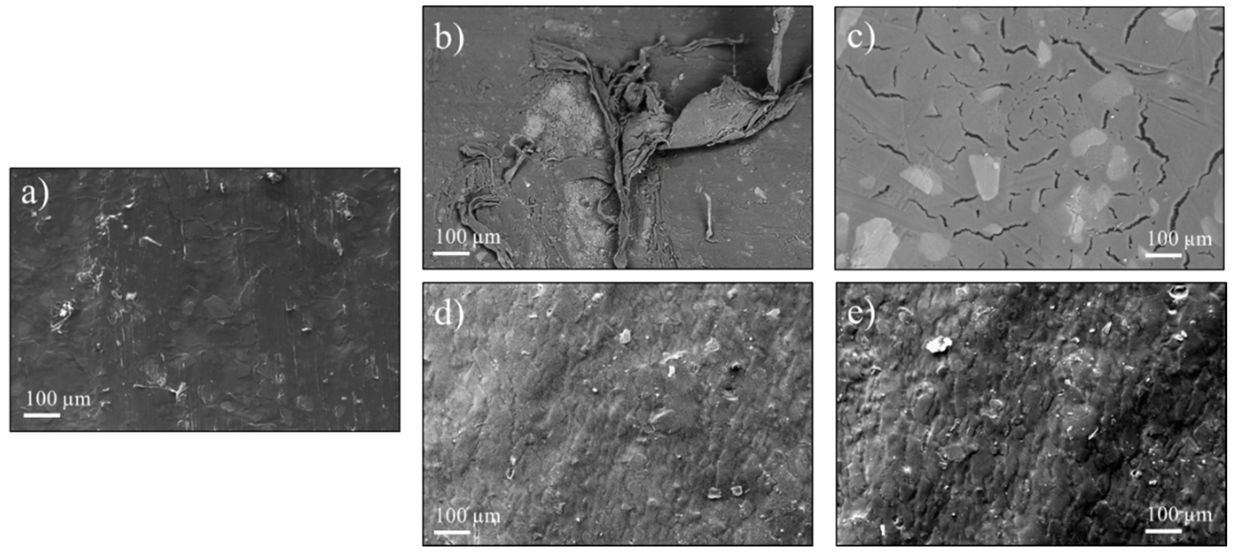
Figure 2 compares the surface morphologies of different samples, studied by means of SEM. Comparing the surface of a pristine sample (
Figure 2a) with the in-service-failed sample (
Figure 2b,c), it is possible to verify the extensive damage that occurred on the coating. Severe detachment and crazing phenomena are clear and both lead to the exposure of the substrate after failure.
Figure 2d,e shows the alteration of the surface morphology for both thermally aged and life-tested samples, respectively. In both cases, the surface has become wrinkled, and ridges have started to appear.
The study of life-tested samples at higher magnification revealed, however, that small traces of food were still present on the surface, and that crazing phenomena had occurred but on a smaller scale. The whitened areas highlighted in
Figure 3a represent the early stages of crazing. This phenomenon manifested in areas close to carbonized residues (white arrow in
Figure 3a), with an average width of about 1 µm, as can be seen at higher magnification in
Figure 3b.
The coating cross sections were also analyzed by means of SEM.
Figure 4 shows the structure of a pristine PTFE-based coating consisting of two layers: the primer and the top coat. The first is a composite that adheres to the substrate, consisting of small TiO
2 particles (average size < 100 nm) embedded in a PTFE resin. The interface between the primer and the substrate shows no imperfections and appears to be solid over the whole surface. The top coat is a PTFE matrix containing mica lamellae, shown in
Figure 4 as clearer, elongated elements.
The chemical analyses of the areas highlighted in
Figure 4 are shown in
Table 2. Spectrum 1 shows the composition of the primer, showing signals from the PTFE resin (C and F) and from the TiO
2 particles. Spectrum 2 consists only of C and F signals, as expected. The composition of Spectrum 3 is compatible with the chemical composition of mica minerals [
13].
The cross section of an in-service-failed sample is shown in
Figure 5. The coating–substrate interface delaminated at multiple points, indicated with white arrows in
Figure 5a. In other areas this interface remained mostly intact, while the interface between the polymeric matrix and the mica lamellae had started to show degradation, as seen in
Figure 5b. Both these failure modes are present in
Figure 5c, in which part of the coating has already detached from the substrate but has also started to deteriorate internally.
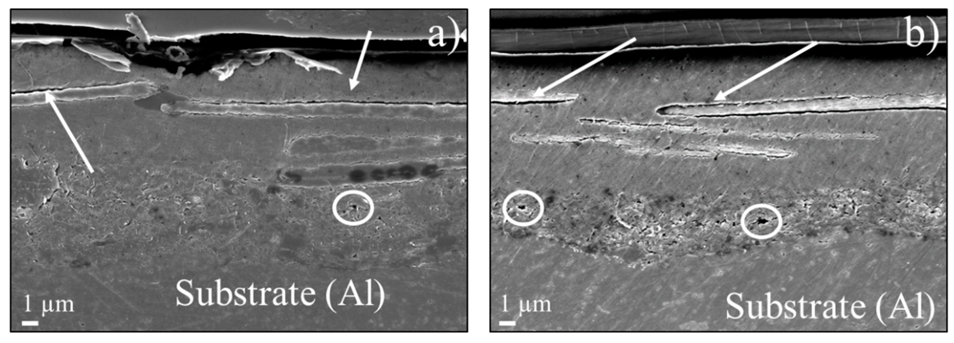
The cross sections of life-tested and thermally aged samples are shown in
Figure 6a,b, respectively. In both pictures there are signs of early degradation. The areas surrounding the mica lamellae present signs of damage (indicated by white arrows) and the primer layer has started to show the formation of cavities, although the damage in the primer layer of the life-tested sample appears to be less severe.
The normalized FT-IR spectra acquired for the studied samples are shown in
Figure 7a. There are no significant differences in the fingerprint area, while the peaks around 3000 cm
−1 change depending on the sample. These peaks refer to aliphatic CH
2 and CH
3 asymmetric stretching [
14]. This could be attributed to the presence of a different polymer inside the blend, together with PTFE. The expanded spectra in
Figure 7b show that the signal completely disappears in the in-service-failed sample and is greatly reduced in the thermally aged sample. The life-tested sample, on the other hand, has its intensity reduced but not as severely.
4. Discussion
In this work, a PTFE-based coating normally used in food service applications was artificially aged and compared to failed coatings in order to understand the starting point of the degradation mechanism. The visual inspection of the pristine and in-service-failed samples (
Figure 1a,b, respectively) clearly shows that the coating has changed color, going from dark gray to almost white, has lost its anti-stick properties allowing severe fouling, and has partly detached from the substrate, exposing the substrate. Both the thermally aged and life-tested samples, on the other hand, appear unchanged.
The investigation of these samples by means of SEM revealed additional information on sample degradation. The pictures acquired on the failed sample confirmed the coating detachment (
Figure 2b) but also revealed extensive crazing phenomena (
Figure 2c). The appearance of several microcracks on the coating surface can be attributed to “environmental stress cracking” [
15,
16]. The simultaneous effects of heat, wear, and load resulted in coating failure even though the stress levels were below the failure limits. The thermal degradation of the coating’s polymeric matrix was enhanced by the mechanical wear and by the aggressive substances employed during the routine cleaning processes, leading to the formation of the observed crack network.
Aged samples did not show any sign of degradation on the macroscopic scale (
Figure 1c,d), but an in-depth analysis revealed phenomena that had altered the coating surface morphology. The surface was not as flat as the pristine surface and had become “wrinkled”.
Figure 2d,e shows that ridges appeared on the surface, suggesting a plastic deformation of the coating. This effect can be attributed to the heating process since there was no cleaning procedure and therefore no wear or chemical attack. Fouling was found on the life-tested sample and the early stages of crazing were detected (
Figure 3), although the magnitude was less than in the case of the failed samples. In this case, mechanical cleaning was performed, and the damage could be due to both heating and wear. The life-testing process led to surface degradation phenomena more similar to the realistic case (i.e., the in-service-failed sample).
The cross-sectional morphological and chemical analyses (
Figure 4 and
Table 2, respectively) of the pristine sample confirmed the composition of the coating and the presence of a primer and a top coat. The first consisted of a polymer matrix containing TiO
2 nanoparticles while the latter had the same matrix but a different filler. Mica lamellae were embedded in the top-coat layer. This is a common industrial practice used to increase PTFE-based coatings’ resistance to wear [
17,
18].
The investigation of the cross section for in-service-failed samples revealed two main failure starting points.
Figure 5a shows an extensive failure of the interface between the substrate and the coating, thus explaining the coating detachment.
Figure 5b shows the failure of the interface between the polymer matrix and some of the lamellae in the top coat. The co-existence of these two phenomena is presented in
Figure 5c, in which both the above-mentioned interfaces had failed, causing the coating to break down at different points at the same time.
The cross sections of the thermally aged and life-tested samples revealed a similar failure mechanism, albeit in the early stages of the process.
Figure 6 shows that there are signs of damage in both the polymer/substrate and the polymer/filler interfaces. These can act as starting points for failure under thermal and mechanical stresses (such as wear phenomena from the cleaning process). In this case, the artificially aged coating showed more evident signs of degradation, more similar to the in-service-failed sample.
Possible explanations for the formation of these defects, could be the polymer blend used for this application or differential thermal dilatation of either the metallic substrate or the mica-based minerals. The FT-IR analysis in
Figure 7 revealed the presence of CH
2 and CH
3 groups, which are normally not present in PTFE. Other polymers, however, are usually employed in PTFE-based blends to modify their mechanical and surface properties or to increase wear resistance [
19,
20,
21]. The C-H bond has lower energy than C-F bonds [
8] and, if stress or heat is applied, is more likely to break down. This could explain the reduction in intensity found for CH
2 and CH
3 groups in
Figure 7b for failed and aged samples. Life-tested coatings had the highest intensity among the degraded samples, suggesting that the performed life test had not entirely replicated the service life of a PTFE-based coating. It could be hypothesized that the life test requires longer testing times and more aggressive food chemicals to successfully replicate the working conditions. Nevertheless, the analysis showed that the early stages of degradation could be found in both simulated ageing cases.
This study showed two main failure mechanisms for anti-stick coatings. In some cases, crazing was the main degradation phenomenon occurring on the surface, while in others, crazing could not be found although the surface appeared to be plastically deformed and “wrinkled”. It could be hypothesized that the reason behind these two different behaviors is related to the interface failure mechanisms seen in the SEM analysis.
The polymer matrix and the substrate have different thermal expansion coefficients [
22,
23], so they behave differently when heated. If the interface between these two materials is strong enough to maintain complete adhesion throughout several thermal cycles, the polymer will undergo fatigue phenomena. This can lead to crazing, especially if the polymer/lamellae interface has already failed at some points, and this could be a starting point for the matrix breakdown. If the adhesion between the polymeric coating and the substrate fails, thermal cycling will not cause fatigue but will cause plastic deformation, commonly called “thermal ratcheting”. This is a common phenomenon in polymers subjected to heat [
7]. The PTFE is strained, and since it is no longer bound to the substrate it starts folding and wrinkling.


