Article

Experimental Study on Axial Compressive Behavior of Gangue Aggregate Concrete Filled FRP and Thin-Walled Steel Double Tubular Columns

1
Jiangsu Key Laboratory of Environmental Impact and Structural Safety in Engineering, School of Mechanics and Civil Engineering, China University of Mining and Technology, Xuzhou 221116, China
2
Jiangsu Collaborative Innovation Center for Building Energy Saving and Construction Technology, Xuzhou 221116, China
3
Jiangsu Design Institute of Geology for Mineral Resources, Xuzhou 221006, China
4
CNACG Key Laboratory of Mineral Resource in Coal Measures, Xuzhou 221006, China
*
Author to whom correspondence should be addressed.
Coatings 2021, 11(11), 1404; https://doi.org/10.3390/coatings11111404
Submission received: 22 October 2021 / Revised: 11 November 2021 / Accepted: 12 November 2021 / Published: 18 November 2021
(This article belongs to the Special Issue Interface and Surface Modification for Durable Concretes)

Abstract

:
In the present paper, the monotonic axial compression test of gangue aggregate concrete filled Fiber reinforced polymer (FRP) and thin-walled steel double tubular columns (DTCC) was carried out, and the gangue aggregate concrete filled FRP tubular columns (CFFT) were designed as a comparison. The main experimental factors were the confinement level of the FRP jacket, the relative diameter ratio (the ratio of the outer diameter of the steel tube to the inner diameter of the FRP jacket), and the different strengths of gangue aggregate concrete. The test results show that the bearing capacity and ductility of gangue aggregate concrete in CFFT were significantly improved. As the local buckling of thin-walled steel tube was effectively inhibited, the load bearing capacity of DTCC was further improved compared with CFFT, but the change of dilation behavior and ductility was insignificant. By analyzing the bi-directional stress state of the steel tube, the confinement level of the external FRP jacket was the most sensitive factor affecting the hoop stress of the steel tube, and the axial stress was obviously weakened under the bi-directional stress state. In addition, with the increase of steel tube diameter, the confinement effect of steel tube in DTCC became more obvious.

1. Introduction

Coal gangue is the major industrial waste produced during mining, accounting for 10%–20% of annual coal production in China [1]. This kind of industrial waste will cause serious pollution to the environment in which it is piled up, and with the cumulative increase of coal production, the treatment of this associated waste had gradually become the focus of scholars [2,3]. The coal gangue was used as coarse aggregate to prepare coal gangue aggregate concrete (hereinafter referred to as GAC) as the support system under the mine or applied in the infrastructure construction of the mining area, which is the most economical and popular practice at present [4,5]. However, due to the low stiffness, low strength and high brittleness of GAC, it is difficult to meet the load environment requirements in key parts such as the main tunnel under the mine and the roadside support along the goaf. Therefore, some scholars [6,7,8] had adopted steel tube to confine GAC (concrete filled steel tubular columns, CFST) as illustrated in Figure 1a. However, when subjected to the axial load, the steel tube of CFST is generally prone to local buckling, and when the rock stratum collapses, the internal stress of the rock stratum continues to redistribute, especially in the environment of rock-burst and other special loads, the local stress concentration of the rock stratum will lead to the premature local deformation of the steel tube, which will affect the safety of underground support [8]. If the thickness of the steel tube is increased to avoid local buckling, it may lead to the problems of high cost and high self-weight. In addition, the steel tube is easily eroded by prolonged exposure to the underground environment, resulting in a decline in mechanical properties.
Different from steel with large plastic deformation, fiber-reinforced polymer (FRP) has the advantages of having light weight and high strength and elastic modulus and being linear elastic brittle materials [9]. Therefore, FRP was not only widely used to reinforce existing concrete members but also proposed to replace steel tube in CFST [10], forming the concrete-filled FRP tubular columns (CFFT), as shown in Figure 1b. Due to the neglect of vertical stiffness, FRP jacket will not exhibit local buckling similar to steel tube, and the elastic modulus can be fully used to confine the concrete core. In addition, it also has the characteristic of resisting the erosion of the external harsh environment. Many scholars [10,11,12,13,14,15,16,17,18,19] had conducted sufficient experimental and theoretical research on the hybrid columns and formulated reasonable design suggestions. However, the axial stiffness of CFFT is smaller than that of CFST [20], especially for confined GAC columns. Therefore, some scholars [21,22,23,24,25,26,27,28,29,30] also proposed the FRP-confined concrete-filled Steel Tubular Columns (FCCFT), as shown in Figure 1c, and conducted a series of tests and theoretical studies. Wrapping FRP directly on the outer surface of the steel tube can not only inhibit local buckling but also make the concrete inner core in a dual-confined state, and the corrosion of the steel tube under harsh environment can be effectively blocked.
Teng [31] proposed double-tube concrete columns (DTCC) based on the FCCFT as shown in Figure 1d. Different from FCCFT, the concrete in DTCC is divided into two parts by steel tube: concrete ring (sandwich concrete between steel tube and FRP jacket) and concrete core (concrete inside steel tube). This change can not only ensure the bearing capacity and stiffness of the column but also reduce the self-weight and steel consumption. Subsequent scholars had conducted different series of studies by replacing steel tubes with high-strength steel tubes in DTCC [31], square sections [32,33,34], and different filled concrete [35,36], respectively. In view of the characteristics of low strength, low stiffness, and high brittleness of GAC, combined with the thin-walled steel tube with lightweight and convenient underground transportation, the DTCC hybrid form can not only improve the strength and ductility of GAC through confinement but also effectively restrain the local buckling of thin-walled steel tube. Thus far, there are not yet reports about the application of GAC and thin-walled steel tube in DTCC. Therefore, it is meaningful to carry out a systematic experimental study, analyze the interaction mechanism among its components, and provide some design suggestions for the application of GAC under the mine.
When this kind of composite column is applied in the foundation construction of mining area, especially as roadway side support or permanent support under the mine, its specific implementation scheme is a problem worthy of attention. Since composite columns do not need to be connected with beams and other components when they are used in mines, they can be prefabricated in advance in the ground precast site. The external FRP jacket can be used as a mold for gangue concrete casting if tubular profiles are used. If the external FRP jacket is formed by the method of manual winding, a mold of corresponding size is required to temporarily replace the FRP jacket during concrete pouring, and the FRP cloth shall be pasted by wet wet-layup process after 21 days of curing. After the prefabricated column is transported to the support position, the connection material is placed between the composite column and the supported position for support assembly adjustment. It is worth noting that when the support requirement is given deformation, the connecting material should have a large deformation capacity; when the support requirement is limited deformation, the connecting material should have sufficient strength and stiffness. In the present paper, the monotonic axial compression test of the hybrid column was carried out considering different Carbon fiber reinforced polymer (CFRP) jacket thicknesses, plain strengths of GAC and relative diameter ratios φ. At the same time, a comparative analysis of GAC in CFFT and DTCC specimens was carried out, and the stress states of thin-walled steel tubes and the combined effects of each component in DTCC were also discussed.

2. Experimental Program

2.1. Material Properties

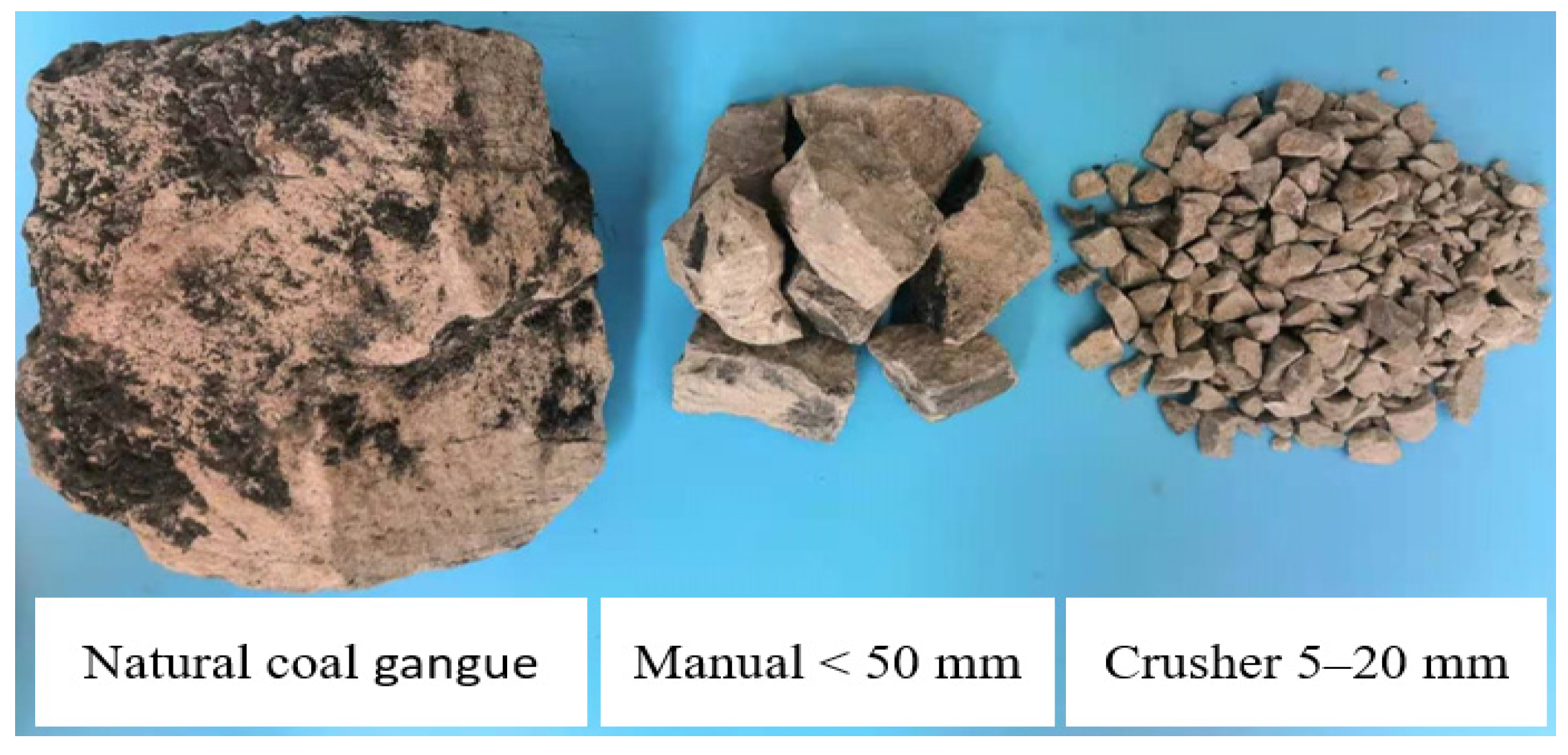
2.1.1. Gangue Aggregate Concrete
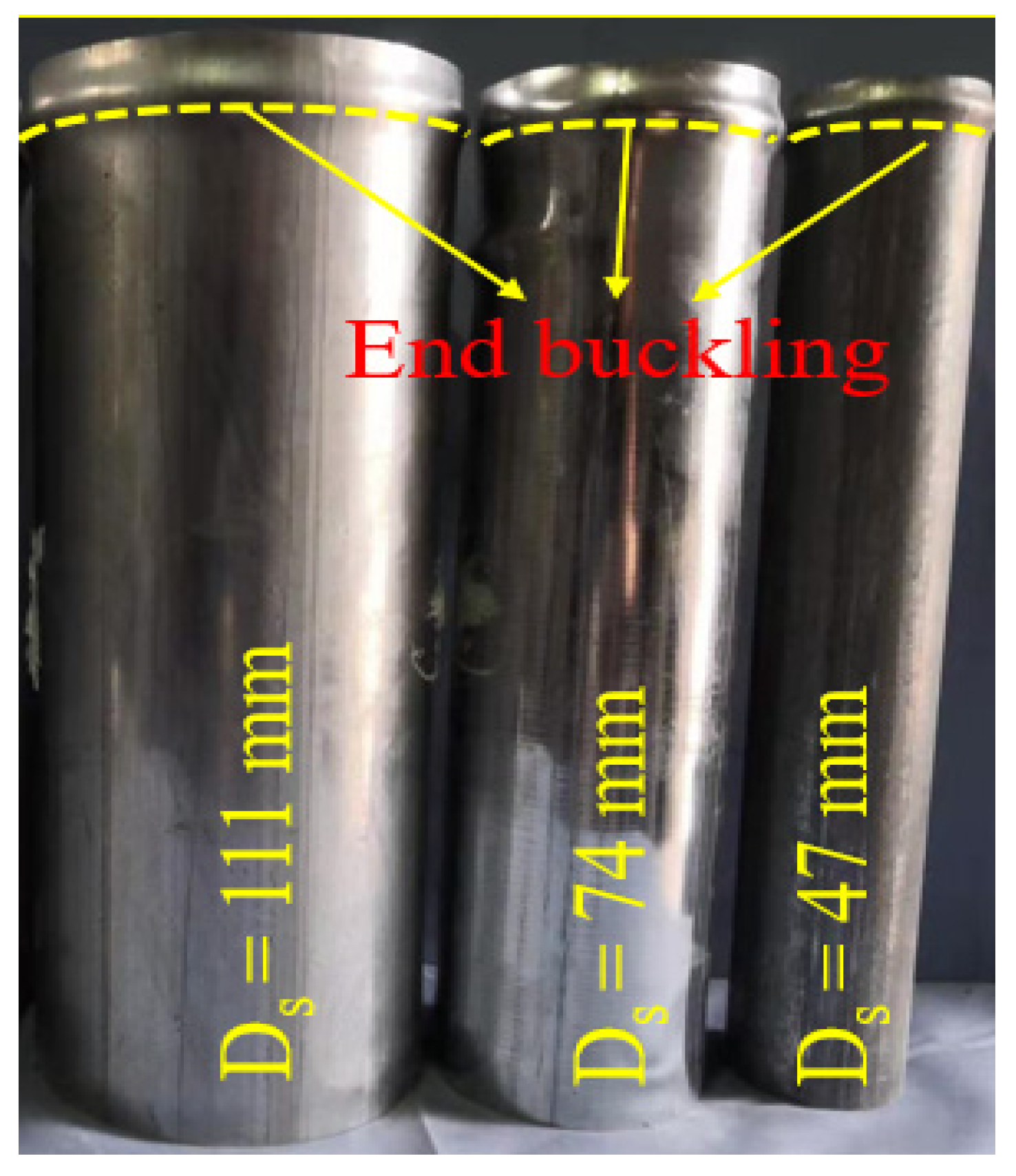
Gangue aggregate concrete (labeled as GAC hereafter) was mainly composed of gangue coarse aggregate (labeled as GA hereafter), desalinated marine sand, cement, water and water reducing agent. In order to research the effects of different GAC strengths on the mechanical properties of the composite columns, and considering the low strength of gangue coarse aggregate, three standard cylinder (Φ300 mm × 150 mm) strength types with target values of 30, 35, and 40 MPa were designed as variables in the test. The detailed mix ratio and mechanical properties are summarized in Table 1, and the final axial strength of plain concrete was calculated by the average of the experimental results of three nominally identical columns. The gangue coarse aggregate used in the test is sandstone gangue (Figure 2), which has a bulk density of 1222 Kg/m3, the cylindrical strength is 7.2 MPa, and the water absorption is 1.34%. After two crushing procedures of manual and crusher, the particle size was mainly distributed within 5–20 mm. In addition, the water absorption rate of gangue coarse aggregate was marginally higher than that of nature coarse aggregate (about 0.4%) [37], so the water absorption amount of GA was not considered in the preparation of GAC, resulting in the actual compressive strength of the cylinder was slightly higher than the designed target value (Table 1).

2.1.2. Steel Tube

In this test, thin-walled steel tubes with outer diameters of 111, 74, and 47 mm, respectively, were used, and all of them had diameters of 1.8 mm. According to ASTM E8/E8M-13a [38], three steel standard tensile coupons were taken from the same batch of steel tubes respectively for tensile test. In addition, the monotonic axial compression test was carried out on two nominally identical hollow steel tubes, respectively. In order to avoid the unevenness of the end, all the hollow steel tubes were cut accurately by laser on the base metal of the same batch. As shown in Figure 3, after the axial compression, all specimens exhibited end-buckling failure (“elephant foot failure”), and the key results of mechanical properties of steel tubes were summarized in Table 2.

2.1.3. CFRP Jacket

The CFPR jackets were manufactured by wet-layup process using carbon fiber sheet which has a thickness of 0.167 mm and corresponding epoxy resin adhesive. The flat coupon tensile test was conducted according to ASTM-D3039/D3039M-08 [39], the tensile strength and elastic modulus in fiber bundle direction were 242 GPa and 3512 MPa, respectively. The epoxy adhesive supplied by the manufacturer had a tensile strength of 48 MPa and tensile elastic modulus of 2.93 GPa.

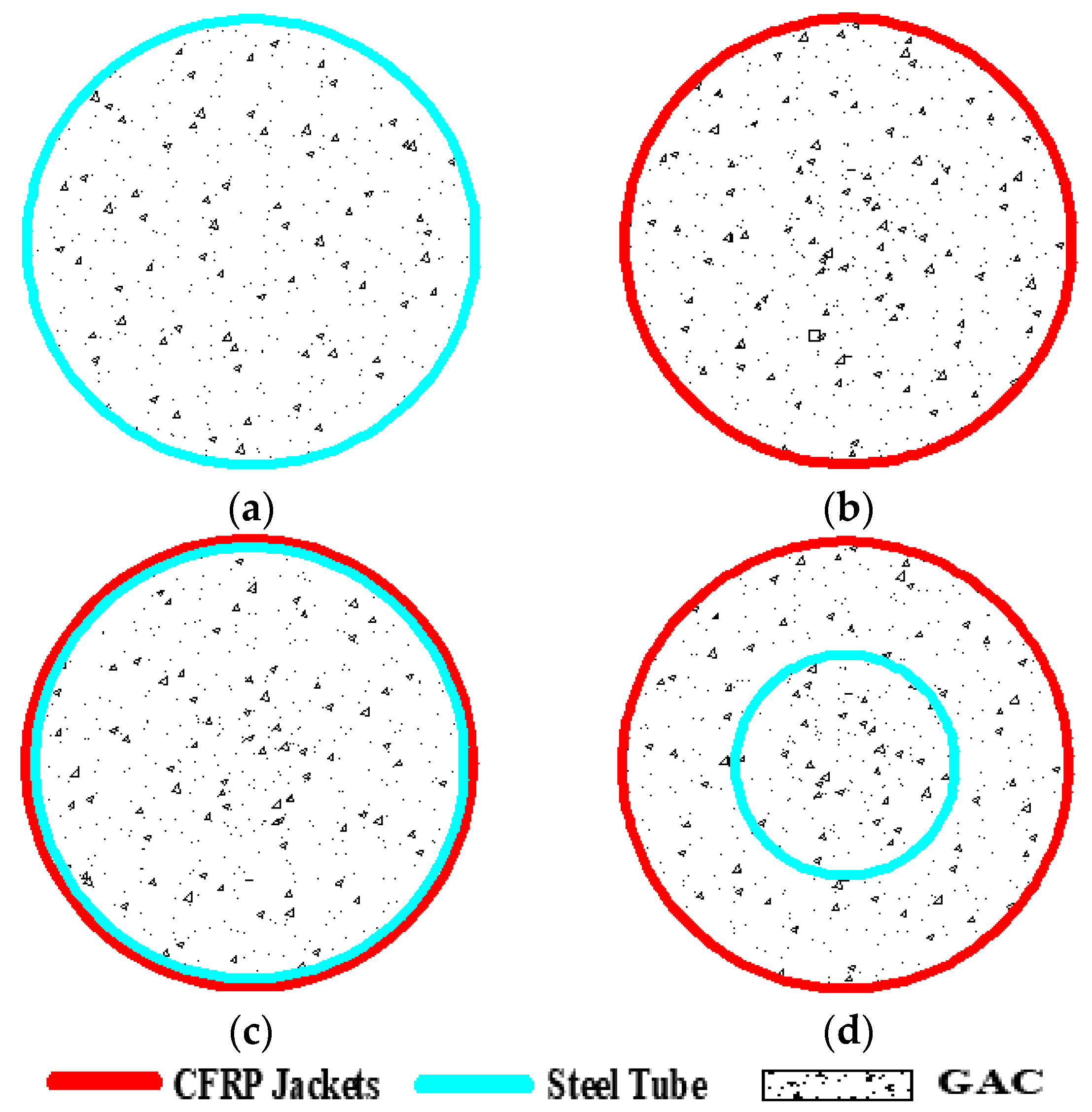
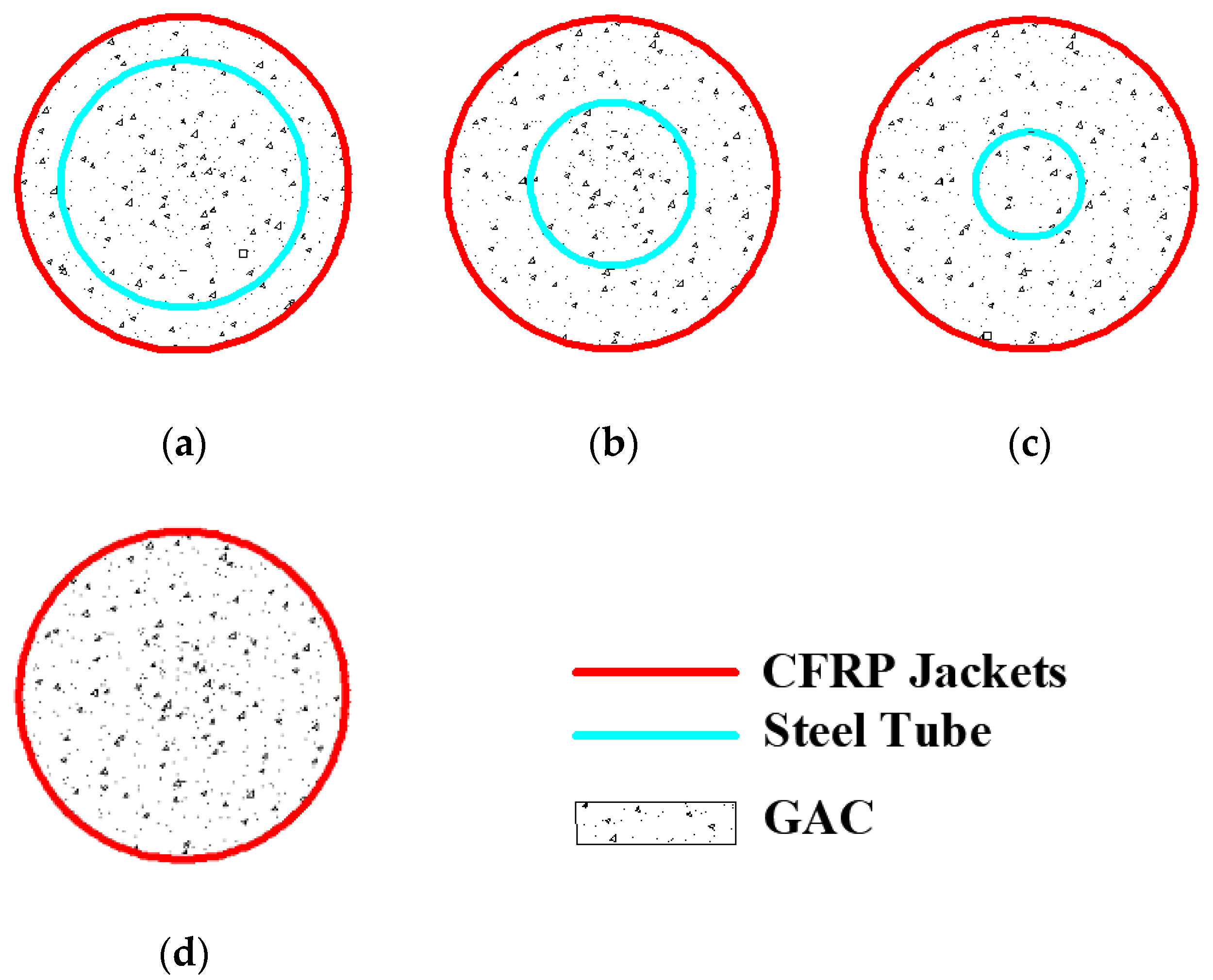
2.2. Specimens Design

A total of 25 columns with a height of 300 mm and a diameter of 150 mm were designed for the monotonic axial compression test. Among them, there are 5 gangue aggregate concrete filled CFRP tube columns (CFFT) and 20 coal gangue aggregate concrete filled FRP-steel double tubular columns (DTCC), as shown in Figure 4. FRP confinement strength, relative diameter ratio, and concrete strength are the main variables considered in this test. The FRP confinement strength was mainly achieved by using 1-ply, 2-ply, and 3-ply of CFRP jacket; the relative diameter ratio refers to the ratio of the outer diameter of the steel tube to the inner diameter of the CFRP jacket (i.e., φ = D s / D f r p , where D f r p is the inner diameter of the CFRP jacket, DS is the outer diameter of the built-in steel tube). In order to investigate the effect of the built-in steel pipes on the mechanical properties of the composite columns, four types of relative diameter ratios of 0, 0.31, 0.49, and 0.74 were adopted in this test. For convenience of reference, each test specimen was assigned a label, taking M111F1-2 as an example, M represents a plain concrete strength of 37.5 MPa, 111 represents that the outer diameter of steel tube is 111 mm (i.e., a relative diameter ratio of 0.74), F1 means that the specimen was confined by 1-ply of CFRP jacket, and the Arabic number 2 is the second of the two identical specimens. The details of all specimens are summarized in Table 3.

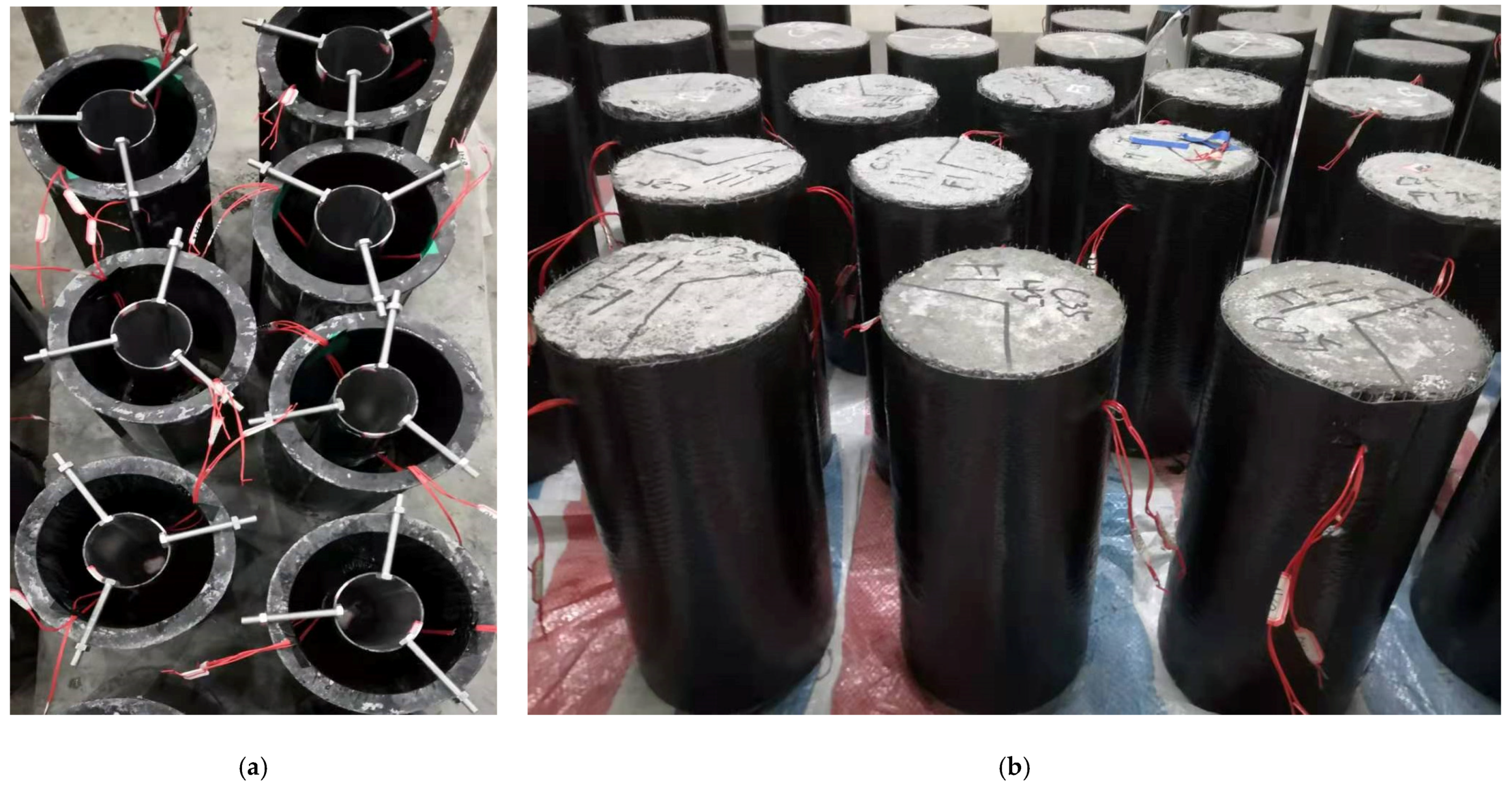
2.3. Preparation of Specimens

For the GAC filled CFRP tubular columns (CFFT), the standard cylindrical plastic molds with a size of Φ 150 mm × 300 mm were used for plain concrete casting, and after curing for 21 days, the carbon fiber sheets were wrapped around the surface of the plain concrete column along the fiber bundle direction by wet-layup process. In addition, for DTCCs with built-in steel tubes, three sets of bolts with each at an angle of 120° apart were used to fix the steel tube to the standard cylindrical mold on the same axis (Figure 5a). In order to prevent the bolts from loosening during the concrete vibrating process, the fixed bolts and the plastic mold were reinforced with strong adhesive. The bolts were removed at the end of the concrete pouring process, and the CFRP jacket was also wrapped after 21 days of maintenance. In order to avoid the debonding failure of CFRP jacket, an overlapping zone of 150 mm was set for all confined specimens. Due to the large stress concentration at the ends of the column during the loading process, two layers of CFRP strips with a width of 25 mm were wrapped at the both ends of each specimen for reinforcement. Before the monotonic axial compression test, all CFRP jackets were cured for 7 days to meet the bonding strength requirements of the epoxy resin as shown in Figure 5b.

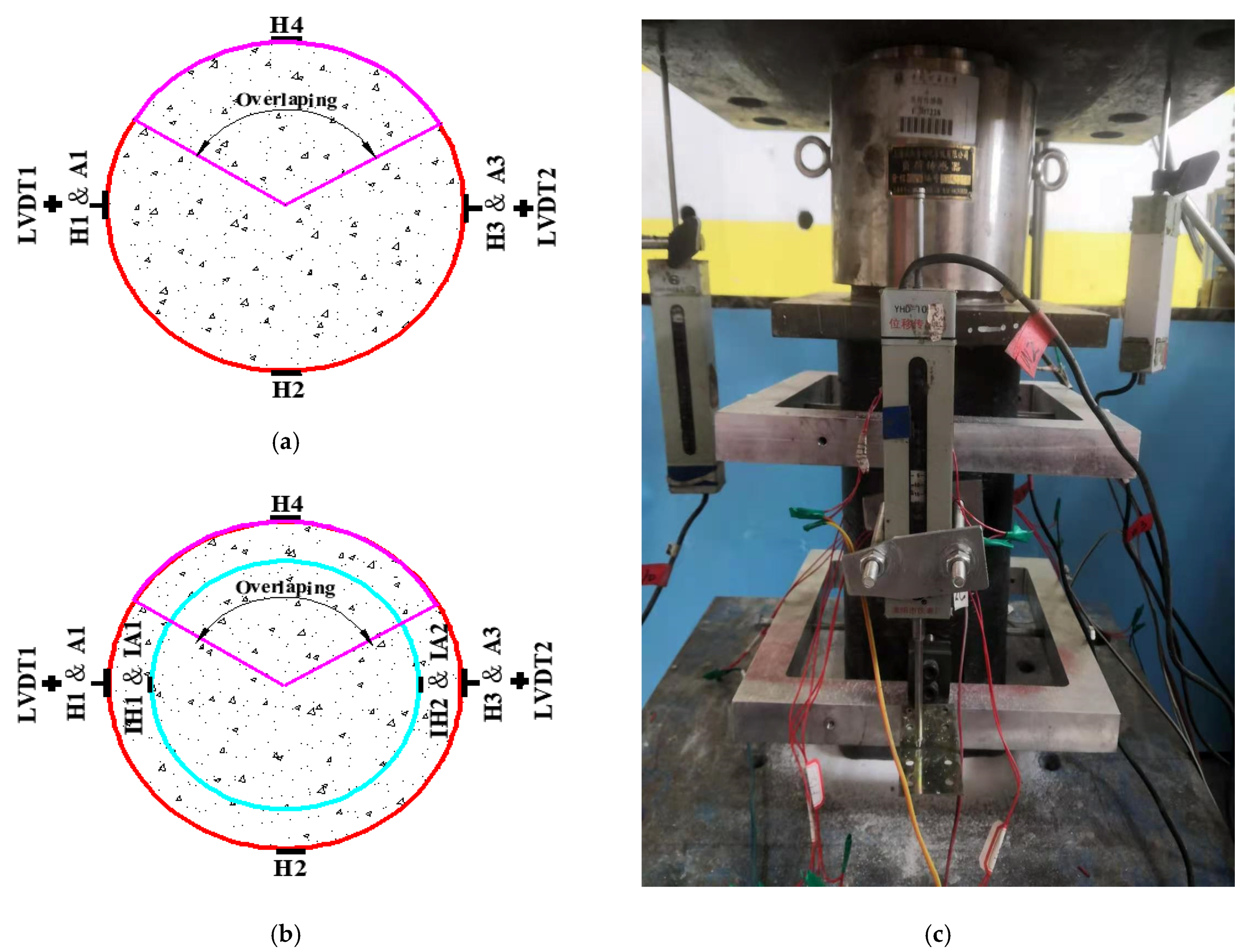
2.4. Test Setup and Instrumentation

The axial compression process was carried out using a 7000 KN servo hydraulic testing machine with a displacement control rate of 0.5 mm/min. The applied load was collected by a force sensor installed in at the upper end of the columns, and each specimen was preloaded and adjusted to minimize the influence of eccentric compression; the loading device was illustrated in Figure 6c.
As shown in Figure 6a,b, for all the confined specimens, four 20 mm lateral strain gauges were uniformly arranged in the mid-height of each column along the hoop direction to measure the lateral strain, and another two 20 mm axial strain gauges were symmetrically arranged in the mid-height of the specimen. Since the axial strain gauges may experience bending effects during loading process and coupled with its relatively small detectable scale distance, the axial deformation was mainly measured by two linear variable displacement transducers (LVDTs) set on the symmetry plane using a high-strength aluminum alloy frame in the middle height of column within 180 mm, and the axial strain gauges were mainly used to verify the accuracy of LVDTs at the initial loading stage. In addition, another two LVDTs were also installed to monitor the vertical displacement control of the testing machine. All experimental data were simultaneously recorded and saved by the same data logger.

3. Experimental Results

3.1. Failure Modes

Figure 7 shows the typical failure modes of the test columns, where all CFFT and DTCC had similar damage forms, mostly appearing as external CFRP jackets being ruptured at mid-height positions. Due to insufficient reinforcement and stress concentration at the ends of the confined columns, similar to Figure 7e, H111F2-1, H111F2-2, and H111F3 exhibited a ruptured of the FRP jacket at the upper end (which means that the predetermined ultimate load bearing capacity has not been reached). As thin-walled steel tubes were used in DTCC components, local buckling of steel tubes with outer diameters of 111 and 74 mm occurred immediately after the failure of CFRP jacket as shown in Figure 7f. Therefore, similar to CFFT, the axial compression test of DTCC components was considered to be finished when the CFRP jacket was ruptured.
As shown in Figure 7a, for the CFFT, the GAC core mainly underwent oblique shear “conical failure” when the external CFRP jacket was ruptured. For DTCC, the GAC ring (GAC between CFRP jacket and steel tube) exhibited oblique shear and peel failure mainly in the CFRP fracture zone. When the relative diameter ratio was φ = 0.31 (i.e., DS = 47 mm), the failure mode tended to be more like that of the CFFT specimens, and as the relative diameter ratio reached 0.74 (i.e., DS = 111 mm), the oblique shear failure of the GAC ring was not obvious and tended to be more of a peeling failure mode due to the steel tube taking more of the shear load (Figure 7d).

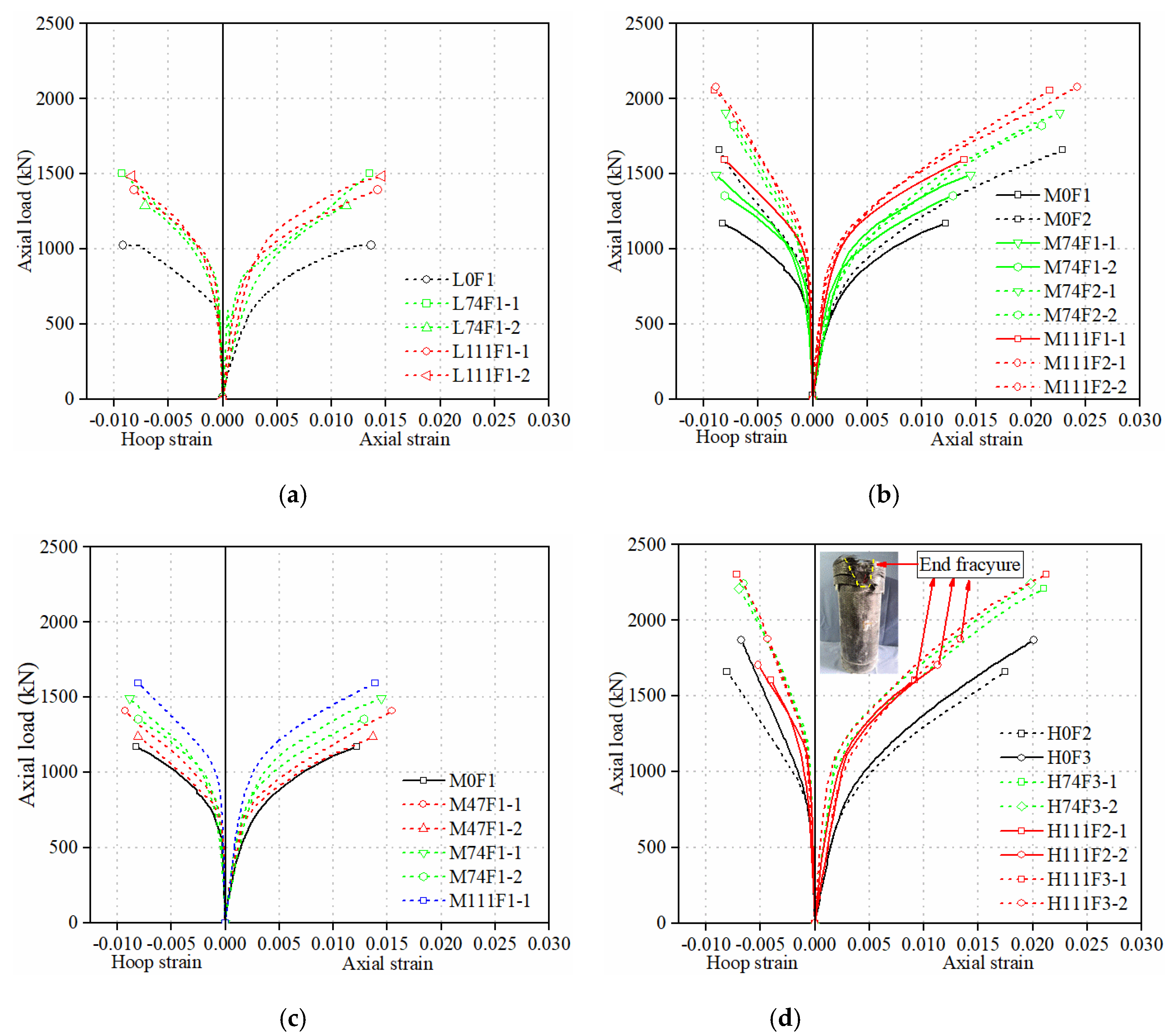
3.2. Load-Axial Strain Behavior

The load-axial strain curves for all confined columns as well as the load–hoop strain curves are illustrated in Figure 8, and the key results are summarized in Table 4. In addition, P c o and ε c o represent peak load and corresponding axial strain of plain concrete cylinder, respectively; P c c and ε c c , respectively, mean the ultimate load and the corresponding axial strain of the confined specimens without internal steel tube; P c u and ε c u , respectively, represent the ultimate load and corresponding axial strain of confined specimens with the built-in steel tube, P c c / P c o and ε c c / ε c o represent the improvement of the ultimate load of the CFFT relative to the plain concrete columns and the corresponding improvement of the ultimate axial strain, respectively. P c u / P c c and ε c u / ε c c represent the increase in the ultimate load of the DTCC relative to the CFFT with the same plain concrete strength and the corresponding enhancement of the ultimate axial strain, respectively. The axial strain was calculated by dividing the LVDTs reading in the middle of each specimen by 180 mm, while the hoop strain was taken as the average value of three hoop strain gauges outside the overlapping zone. Unless otherwise specified, the convention that the axial stress and the corresponding strain were determined as positive values and the hoop strain as negative values was observed.
As summarized in Table 4, the ultimate bearing capacity of CFFT showed an increasing trend with the improvement of peak load of plain concrete under the same confinement strength, but the relative improvement factor slightly decreased; the bearing capacity and axial strain of CFFT specimens were significantly improved with the increase of the thickness of the CFRP jacket. Due to the axial bearing capacity and hoop stress provided by the internal steel tube, the DTCC specimens had a certain increase in load bearing capacity compared to the CFFT specimens. The improvement range was 1.16–1.44 times for one-layer CFRP jacket, and enhancement range was 1.1–1.25 times for the two-layer and three-layer CFRP jacket, which indicated that with the increase of thickness of CFRP jacket, the relative increase rate of the load bearing capacity of DTCC exhibited a decreasing trend. As shown in Figure 8, the load-axial strain as well as the load–hoop strain curves of all columns showed a bilinear relationship with a second hardened stage. Under the same plain concrete strength and CFRP jacket thickness (Figure 8a,c), the second portion of the load-axial strain curves exhibited a more excellent hardening behavior with the increase of relative diameter ratio (i.e., the increase of outer diameter of built-in steel tube), and the load carrying capacity also had an increasing trend, but the difference in the axial strain was insignificant. Under the same plain concrete strength and relative diameter ratio φ (Figure 8b), the load bearing capacity and axial strain of DTCC specimens were significantly improved with the increase of CFRP jacket thickness. In addition, the specimens H111F2-1, H111F2-2, and H111F3-2 did not reach the ultimate load bearing capacity due to the end stress concentration failure during the test (Figure 8d), but they exhibited similar mechanical behavior to that of normal specimens before the end damage.

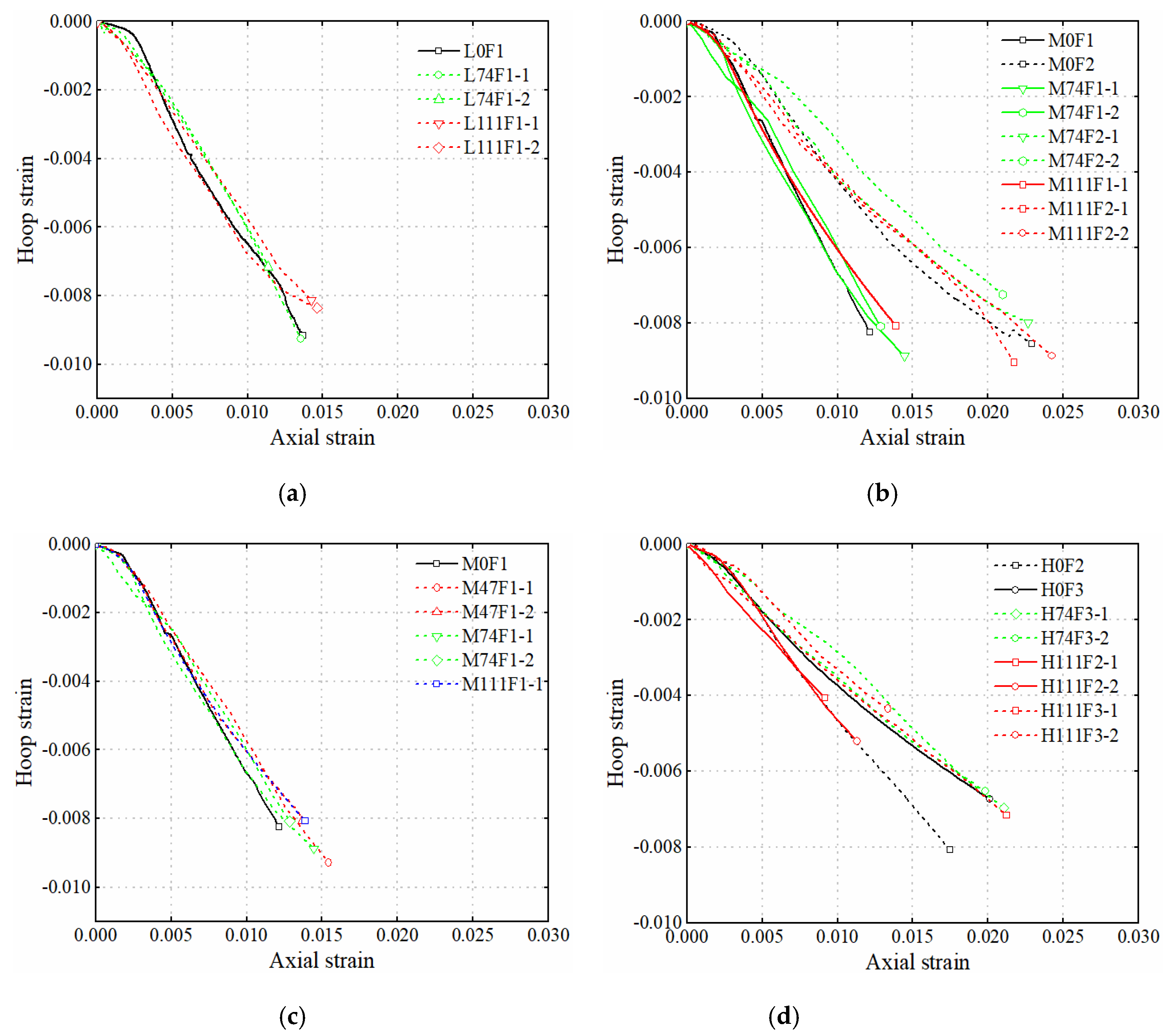
3.3. Axial Strain-Hoop Strain Behavior

The dilatation behavior of the confined specimens was characterized by the axial strain–hoop strain relationship, and corresponding curves of the confined columns were illustrated in Figure 9. As shown in Figure 9b,d, for CFFT and DTCC, with the increase of CFRP jacket thickness, their corresponding hoop strain tended to increase (i.e., the absolute value decreased) under the same axial strain. It is indicated that the lateral dilatation of all the confined specimens became more insignificant with the increase of the external confinement level. When the steel tube was built into the confined column, the difference in lateral dilatation was not significant compared to the CFFT, but the DTCC also exhibited a slightly smaller hoop strain for a given axial strain, indicating that the steel tube had a certain confinement effect on the concrete core. However, an insignificant difference was observed in the dilation behavior of DTCC specimens with the change of steel tube diameter in present test.

4. Mechanical Behavior of Steel Tubes

4.1. Slip between Steel Tube and GAC

Since the steel tube had different axial stiffness and Poisson’s ratio relative to GAC, there may be slippage during their joint loading process. Figure 10 illustrated the typical relationship between external CFRP jackets and internal steel tubes of the same type of strain (including axial strain and hoop strain). Since no debonding phenomenon was observed in the failure modes of all the specimens, it was considered that the axial strain of the GAC was consistent with the strain of the CFRP jacket, which was taken from the average of two vertical LVDTs readings with a scale distance of 180 mm. As shown in Figure 7f, the built-in steel tube generally buckled outward in the middle region, indicating that the stress of the tube was effectively transferred to the region, so the axial strain and hoop strain were taken to be the average value of the two pairs of strain gauges attached on the mid-height of steel tube. For columns with different relative diameter ratios, the axial and hoop strains between the steel tube and GAC were slightly different throughout the loading process as shown in Figure 10. In the first portion of the corresponding load versus axial and hoop strain bilinear curves (the axial strain was about 0–0.002), the slip between the steel tube and GAC exhibited an aggravated tendency with the increase of strain. When corresponding to their second portion, the slip phenomenon gradually weakened, and the steel tube and GAC almost entered the state of cooperative deformation until the end of the loading.

4.2. Bi-Directional Stress State of Steel Tube

Unlike CFRP jacket with unidirectional mechanical properties, steel is a kind of isotropic material, so the mechanical behavior of steel tube inside concrete is more complex during axial compression. Under the constraint of GAC, axial compressive stress, lateral tensile stress, and radial stress were mainly generated by the built-in steel tube. Since the radial stress was very small compared with the axial stress and lateral stress it can be ignored for the sake of simple calculation. Therefore, the stress behavior of the built-in steel tube can be simplified to the plane bi-directional stress state (i.e., axial compressive stress and lateral tensile stress). In the present paper, the strain state in the mid-height of the steel tube combined with the classical J 2 flow theory and Mises yield criterion [27] were used to investigate stress states of the steel tube. In order to facilitate the calculation, the Poisson’s ratio of the steel tube was uniformly adopted as 0.3. The convention that the axial stress were determined as positive values and the hoop stress as negative values was observed.
The mechanical behavior of the steel tube conformed to the generalized Hooke’s law at the elastic stage, and the relationship between the stress increment and the corresponding strain increment satisfied Equation (1). In addition, the Mises criterion (Equation (2)) was quoted to determine whether the steel tube had reached the yield state, and the stress state was calculated using Equation (1) before the equivalent force calculated using Equation (2) reached the yield strength obtained from the material test of steel tube.
[ d σ a i d σ h i ] = E s 1 v 2 [ 1 v v 1 ] [ d ε a i d ε h i ]
σ y = σ a 2 + σ h 2 σ a σ h
where E s is the elastic modulus; v is Poisson’s ratio; σ a and ε a are the axial stress and corresponding axial strain, respectively; σ h and ε h are the hoop stress and corresponding hoop strain, respectively; σ y is the Mises stress.
[ d σ a i d σ h i ] = E s 1 v 2 [ 1 ( f a 2 / f c ) v ( f a f h / f c ) v ( f a f h / f c ) 1 ( f h 2 / f c ) ] [ d ε a i d ε h i ]
f a = σ a + v σ h
f h = σ h + v σ a
f c = σ a 2 + σ h 2 + 2 v σ a σ h
σ a = 1 3 ( 2 σ a i 1 σ h i 1 )
σ h = 1 3 ( 2 σ h i 1 σ a i 1 )
The typical bi-directional stress-axial strain curves are illustrated in Figure 11. As shown in Figure 11a, under the same CFRP jacket thickness, the difference of axial stress was not obvious with the increase of steel tube diameter, which is mainly due to their similar yield strength (Table 2). After reaching the yield strength, due to the continuous increasing hoop stress, the axial stress experienced a small decreasing segment and then remained almost constant with the increase of axial strain, which also revealed that the local deformation of the steel tube in the DTCC can be effectively inhibited, thus improving the stress transfer and the ductility. When the axial strain reached about 0.003, the hoop stress no longer increased as the axial stress remained stable, which was close to the constant state (the steel tube became active confinement). The development trend of hoop stress with different steel tube diameters was similar but still exhibited a trend where the stress decreased slightly as the diameter of steel tube increased, as shown in Figure 11a. The axial stress state of the steel tube did not change significantly when the confining strength increased, but it had better ductility. In addition, with the increase of the confinement level, the hoop stress exhibited a decreasing trend (Figure 11b).

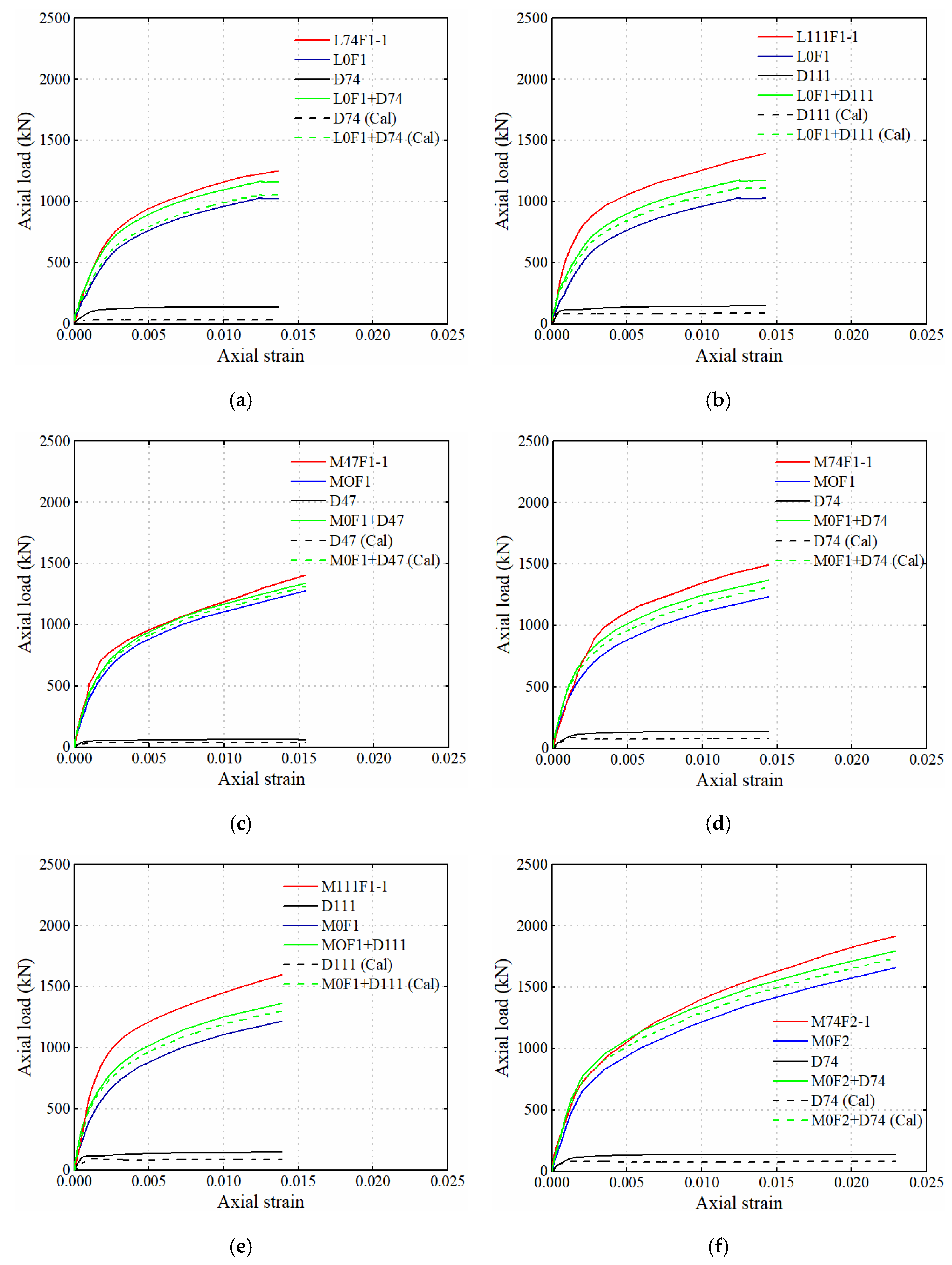
5. Combined Effects of Different Components

In order to further study the interaction mechanism between the different components of the composite column, Figure 12 summarizes the load-axial strain curves for one of the two nominally identical specimens of DTCC, as well as the other five load–strain curves: (1) the load-axial strain curve of CFFT with the same plain concrete strength as DTCC; (2) the load-strain curve obtained from the standard tensile test on the coupons taken from the same batch of steel tubes; (3) the sum of (1) and (2) (i.e., CFFT + Coupon); (4) the load-axial strain curve of steel tube obtained by calculating the bi-directional stress; (5) the sum of (1) and (4). It is worth noting that the strains among the components obtained through the test were not consistent, but the load-strain curves corresponding to (1), (2), and (4) were considered as a straight line in the second segment. In order to calculate the sum of the two curves and facilitate comparison, linear interpolation was used to extend the second portion of some curves to make the strains of the five curves consistent. In addition, the corresponding curves of H111F2-1, H111F2-2, and H111F3-2 were not included in Figure 12 because of the premature end failure.
As shown in Figure 12, the load-axial strain curves of all calculated steel tubes were obviously lower than those obtained from the standard tensile test of coupons, which indicated that the axial bearing capacity of the steel tube inside DTCC was weakened, and the hoop tensile stress was also generated, making the steel tubes in a state of bi-directional stress during the loading process (Figure 11). Therefore, the curve (5) was correspondingly lower than the curve (3). Although curve (3) did not take into account the bi-directional stress state of steel tube (axial stress weakened), it was also lower than the load-strain curve of the corresponding DTCC for all test specimens, and the tendency was more obvious for the curve (5), which revealed that the internal steel tube had a pronounced hoop confinement effect on its concrete core. With the increase of steel tube diameter, the enhancement of load-strain curve of DTCC was more significantly compared with corresponding curves (3) and (5), that is, with the increase of the cross-sectional area of GAC under dual confinement, the confinement effect of steel tube in DTCC was more obvious.

6. Conclusions

In this paper, the GAC fully filled FRP tube column (CFFT) and GAC filled FRP and thin-walled steel double tubular column (DTCC) were experimentally studied, mainly considering the strength of GAC, the thickness of FRP jacket, and the relative diameter ratio. The failure modes, load-strain curves, stress states of steel tubes, and combined effects of each component were discussed, and the following conclusions were drawn:
(1) After wrapped by the CFRP jacket, the bearing capacity and ductility of GAC were both greatly improved; when the steel tube was built-in, the bearing capacity of DTCC was further improved relative to CFFT, and with the increase of the steel tube diameter, this improvement showed a more obvious trend, but the change of ductility was insignificant.
(2) The confinement level of FRP jacket was the most sensitive factor affecting the dilation behavior of all confined specimens, and the dilation behavior of the GAC became more insignificant as the confinement level increases. Given an axial strain, DTCC exhibited a less pronounced dilation behavior relative to CFFT. However, the differences in dilation behavior between DTCC specimens were not obvious as the steel tube diameter changes.
(3) The strain state of the steel tube inside the DTCC had slight hysteresis relative to the GAC during the loading history. This hysteresis can be divided into two stages: (a) the hysteresis increased in the first portion of the corresponding load-axial strain curve; (b) in the second portion of the corresponding load-axial strain curve, the hysteresis decreased continuously and almost entered the cooperative deformation state when the FRP jacket was ruptured.
(4) After the steel tube reached yield strength, the axial compressive stress decreased slightly with the continuous improvement of the hoop tensile stress. The axial stress and the hoop stress remained stable and approximately constant after the axial strain reached 0.003. Under the restriction of concrete ring and concrete core, the local deformation of steel tube was effectively restrained.
(5) The steel tube provided effective lateral confinement to the concrete core, while the axial stress was weakened to some extent. As the cross-sectional area of the concrete core increased, DTCC showed a more excellent strengthening segment, and the bearing capacity was continuously improved.

Author Contributions

Conceptualization, J.X.; methodology, J.W.; formal analysis, J.W.; investigation, J.W.; writing—original draft preparation, J.W.; review and editing, J.X., H.C., Y.H., L.Y., and L.J.; funding acquisition, J.X. All authors have read and agreed to the published version of the manuscript.

Funding

The authors are grateful for the financial support received from the National Natural Science Foundation of China (Grant No. 52074270) entitled “Research on the constitutive model and durability of FRP-constrained coal gangue structure fillings”, CNACG Key Laboratory of Mineral Resource in Coal Measures (Grant No. KFKT-2020-4) entitled “Key technology research on formulation of permeable concrete with solid waste gangue and fly ash”, Jiangsu Collaborative Innovation Center for Building Energy Saving and Construction Technology (Grant Nos. SJXTBS1719, SJXTBZ1705) entitled “Research and Application of New Materials to Solidify Silt Soft Soil, Applied Research on Coal Gangue as Concrete Aggregate”.

Institutional Review Board Statement

Not applicable.

Informed Consent Statement

Not applicable.

Data Availability Statement

Data sharing is not applicable to this article.

Conflicts of Interest

We certify that neither the entire paper nor any part of its content has been published or has been accepted elsewhere. It is not being submitted to any other journal. No conflicts of interest exist in the submission of this manuscript.

References

  1. Liu, H.; Liu, Z. Recycling Utilization Patterns of Coal Mining Waste in China. Resour. Conserv. Recycl. 2010, 54, 1331–1340. [Google Scholar]
  2. Okagbue, C.O.; Ochulor, O.H. The Potential of Cement-Stabilized Coal-Reject as a Construction Material. Bull. Eng. Geol. Environ. 2007, 66, 143–151. [Google Scholar] [CrossRef]
  3. Gao, S.; Zhao, G.; Guo, L.; Zhou, L.; Yuan, K. Utilization of Coal Gangue as Coarse Aggregates in Structural Concrete. Constr. Build. Mater. 2021, 268, 121212. [Google Scholar] [CrossRef]
  4. Zhao, H.; Ren, T.; Remennikov, A. Behaviour of Frp-Confined Coal Rejects Based Backfill Material under Compression. Constr. Build. Mater. 2021, 268, 121171. [Google Scholar] [CrossRef]
  5. Zhao, H.; Ren, T.; Remennikov, A. Standing Support Incorporating Frp and High Water-Content Material for Underground Space. Tunn. Undergr. Sp. Tech. 2021, 110, 103809. [Google Scholar] [CrossRef]
  6. Liu, G.L.; Wang, J.; Wang, H.B.; He, X.S.; Li, X.B. Application Research on Concrete Filled Steel Tube Supports Supporting Technology in Stress Concentration Roadway. Adv. Mater. Res. 2012, 594, 773–778. [Google Scholar] [CrossRef]
  7. Li, X.B.; Ma, Z.X.; Liu, G.L.; Chen, M.C.; Zhu, Q.M. Research on Steel Tube Confined Concrete Supports Support Technology for Soft Rock Roadway in Coal Bed Washout. Appl. Mech. Mater. 2011, 121, 3471–3476. [Google Scholar] [CrossRef]
  8. Li, Q.; Liu, L.; Li, J.K.; Li, Z. Research on D Section Steel Tube Filled with Concrete Used for High Stress Roadway Support in Deep Mines. In Proceedings of the 9th China-Russia Symposium “Coal in the 21st Century: Mining, Intelligent Equipment and Environment Protection”, Qingdao, China, 18–21 October 2018. [Google Scholar]
  9. Zhou, Y.; Liu, X.; Xing, F.; Li, D.; Wang, Y.; Sui, L. Behavior and Modeling of Frp-Concrete-Steel Double-Skin Tubular Columns Made of Full Lightweight Aggregate Concrete. Constr. Build. Mater. 2017, 139, 52–63. [Google Scholar] [CrossRef]
  10. Xiao, Y.; Wu, H. Compressive Behavior of Concrete Confined by Carbon Fiber Composite Jackets. J. Mater. Civ. Eng. 2000, 12, 139–146. [Google Scholar] [CrossRef]
  11. Jiang, T.; Teng, J.G. Analysis-Oriented Stress-Strain Models for Frp-Confined Concrete. Eng. Struct. 2007, 29, 2968–2986. [Google Scholar] [CrossRef] [Green Version]
  12. Teng, J.G.; Jiang, T.; Lam, L.; Luo, Y.Z. Refinement of a Design-Oriented Stress–Strain Model for Frp-Confined Concrete. J. Compos. Constr. 2009, 13, 269–278. [Google Scholar] [CrossRef] [Green Version]
  13. Li, Y.; Zhao, X.; Singh Raman, R.K. Behaviour of Seawater and Sea Sand Concrete Filled Frp Square Hollow Sections. Thin Wall. Struct. 2020, 148, 106596. [Google Scholar] [CrossRef]
  14. Lam, L.; Teng, J.G. Ultimate Condition of Fiber Reinforced Polymer-Confined Concrete. J. Compos. Constr. 2004, 8, 539–548. [Google Scholar] [CrossRef]
  15. Teng, J.G.; Huang, Y.L.; Lam, L.; Ye, L.P. Theoretical Model for Fiber-Reinforced Polymer-Confined Concrete. J. Compos. Constr. 2007, 11, 201–210. [Google Scholar] [CrossRef]
  16. Zhou, Y.; Liu, X.; Xing, F.; Cui, H.; Sui, L. Axial Compressive Behavior of Frp-Confined Lightweight Aggregate Concrete: An Experimental Study and Stress-Strain Relation Model. Constr. Build. Mater. 2016, 119, 1–15. [Google Scholar] [CrossRef]
  17. Chaiyasarn, K.; Hussain, Q.; Joyklad, P.; Rodsin, K. New Hybrid Basalt/E-Glass Frp Jacketing for Enhanced Confinement of Recycled Aggregate Concrete with Clay Brick Aggregate. Case Stud. Constr. Mater. 2021, 14, e00507. [Google Scholar] [CrossRef]
  18. Dang, Z.; Feng, P.; Yang, J.; Zhang, Q. Axial Compressive Behavior of Engineered Cementitious Composite Confined by Fiber-Reinforced Polymer. Compos. Struct. 2020, 243, 112191. [Google Scholar] [CrossRef]
  19. Ye, Y.; Liang, S.; Feng, P.; Zeng, J. Recyclable Lrs Frp Composites for Engineering Structures: Current Status and Future Opportunities. Compos. Part B Eng. 2021, 212, 108689. [Google Scholar] [CrossRef]
  20. Xiong, M.X.; Lan, Z.H.; Chen, G.M.; Lu, Y.C.; Xu, Z. Behavior of Frp-Hsc-Steel Tubular Columns under Axial Compression: A Comparative Study. Compos. Struct. 2021, 261, 113566. [Google Scholar] [CrossRef]
  21. Dong, C.X.; Kwan, A.K.H.; Ho, J.C.M. Axial and Lateral Stress-Strain Model for Concrete-Filled Steel Tubes with Frp Jackets. Eng. Struct. 2016, 126, 365–378. [Google Scholar] [CrossRef]
  22. Liu, L.; Lu, Y. Axial Bearing Capacity of Short Frp Confined Concrete-Filled Steel Tubular Columns. J. Wuhan Univ. Technol. Mater. Sci. Ed. 2010, 25, 454–458. [Google Scholar] [CrossRef]
  23. Wang, Y.; Chen, G.; Wan, B.; Han, B.; Ran, J. Axial Compressive Behavior and Confinement Mechanism of Circular Frp-Steel Tubed Concrete Stub Columns. Compos. Struct. 2021, 256, 113082. [Google Scholar] [CrossRef]
  24. Lu, Y.; Li, N.; Li, S. Behavior of Frp-Confined Concrete-Filled Steel Tube Columns. Polymers 2014, 6, 1333–1349. [Google Scholar] [CrossRef]
  25. Park, J.W.; Hong, Y.K.; Hong, G.S.; Kim, J.H.; Choi, S.M. Design Formulas of Concrete Filled Circular Steel Tubes Reinforced by Carbon Fiber Reinforced Plastic Sheets. Procedia Eng. 2011, 14, 2916–2922. [Google Scholar] [CrossRef] [Green Version]
  26. Wei, Y.; Zhang, Y.; Chai, J.; Wu, G.; Dong, Z. Experimental Investigation of Rectangular Concrete-Filled Fiber Reinforced Polymer (Frp)-Steel Composite Tube Columns for Various Corner Radii. Compos. Struct. 2020, 244, 112311. [Google Scholar] [CrossRef]
  27. Hu, Y.M.; Yu, T.; Teng, J.G. Frp-Confined Circular Concrete-Filled Thin Steel Tubes under Axial Compression. J. Compos. Constr. 2011, 15, 850–860. [Google Scholar] [CrossRef]
  28. Teng, J.G.; Hu, Y.M.; Yu, T. Stress-Strain Model for Concrete in Frp-Confined Steel Tubular Columns. Eng. Struct. 2013, 49, 156–167. [Google Scholar] [CrossRef]
  29. Zhang, Y.; Wei, Y.; Bai, J.; Zhang, Y. Stress-Strain Model of an Frp-Confined Concrete Filled Steel Tube under Axial Compression. Thin Wall. Struct. 2019, 142, 149–159. [Google Scholar] [CrossRef]
  30. Deng, J.; Zheng, Y.; Wang, Y.; Liu, T.; Li, H. Study on Axial Compressive Capacity of Frp-Confined Concrete-Filled Steel Tubes and its Comparisons with Other Composite Structural Systems. Int. J. Polym. Sci. 2017, 2017, 1–7. [Google Scholar] [CrossRef] [Green Version]
  31. Teng, J.G.; Wang, Z.; Yu, T.; Zhao, Y.; Li, L.J. Double-Tube Concrete Columns with a High-Strength Internal Steel Tube: Concept and Behaviour Under Axial Compression. Adv. Struct. Eng. 2018, 21, 1585–1594. [Google Scholar] [CrossRef]
  32. Zeng, J.; Lv, J.; Lin, G.; Guo, Y.; Li, L. Compressive Behavior of Double-Tube Concrete Columns with an Outer Square Frp Tube and an Inner Circular High-Strength Steel Tube. Constr. Build. Mater. 2018, 184, 668–680. [Google Scholar] [CrossRef]
  33. Wang, Z.; Tao, Z.; Yu, Q. Axial Compressive Behaviour of Concrete-Filled Double-Tube Stub Columns with Stiffeners. Thin Wall. Struct. 2017, 120, 91–104. [Google Scholar] [CrossRef]
  34. Louk Fanggi, B.A.; Ozbakkaloglu, T. Square Frp–Hsc–Steel Composite Columns: Behavior under Axial Compression. Eng. Struct. 2015, 92, 156–171. [Google Scholar] [CrossRef]
  35. Ozbakkaloglu, T.; Fanggi, B.L. Axial Compressive Behavior of Frp-Concrete-Steel Double-Skin Tubular Columns Made of Normal- and High-Strength Concrete. J. Compos. Constr. 2014, 18, 4013027. [Google Scholar] [CrossRef]
  36. Li, Y.; Zhao, X. Hybrid Double Tube Sections Utilising Seawater and Sea Sand Concrete, Frp and Stainless Steel. Thin Wall. Struct. 2020, 149, 106643. [Google Scholar] [CrossRef]
  37. Zhao, H.; Ren, T.; Remennikov, A. Behaviour of Frp-Confined Coal Reject Concrete Columns under Axial Compression. Compos. Struct. 2021, 262, 113621. [Google Scholar] [CrossRef]
  38. ASTM. ASTM E8/E8M-21 Standard Test Method for Tension Testing of Metallic Materials; ASTM: West Conshohocken, PA, USA, 2014. [Google Scholar]
  39. ASTM. ASTM D3039/D3039M-17 Standard Test Method for Tensile Properties of Polymer Matrix; ASTM: West Conshohocken, PA, USA, 2008. [Google Scholar]
Figure 1. Different cross-section of composite columns: (a) CFST; (b) CFFT; (c) FCCFT; (d) DTCC.
Coatings 11 01404 g001
Figure 2. The production process of gangue coarse aggregate (GA).
Coatings 11 01404 g002
Figure 3. Failure mode of hollow steel tube under axial compression.
Coatings 11 01404 g003
Figure 4. Schematic diagram of the cross-section of the test specimens: (a) φ = 0.74; (b) φ = 0.49; (c) φ = 0.32; (d) φ = 0.
Coatings 11 01404 g004
Figure 5. The process of preparing test specimens: (a) arrangement of internal steel tubes; (b) maintenance of CFRP jackets.
Coatings 11 01404 g005
Figure 6. Test setup and instrumentation. (a) Instrumentation of CFFT; (b) instrumentation of DTCC; (c) test setup.
Coatings 11 01404 g006
Figure 7. Typical failure modes of experimental specimens: (a) H0F2; (b) M47F1-1; (c) M74F2-1; (d) M111F2-2; (e) H111F2-2; (f) inner steel tube in DTCC.
Coatings 11 01404 g007
Figure 8. Axial load–axial strain curves of all test specimens: (a) series L; (b) series M with different confinement strength; (c) series M with different relative diameter ratios; (d) series H.
Coatings 11 01404 g008
Figure 9. Axial load–axial strain curves of all test specimens: (a) series L; (b) series M with different confinement strengths; (c) series M with different relative diameter ratios; (d) series H.
Coatings 11 01404 g009
Figure 10. Relative slip of steel tubes and CFRP jackets.
Coatings 11 01404 g010
Figure 11. Typical axial strain–bidirectional stress curves for steel tube: (a) influence of relative diameter ratio; (b) influence of confinement strength.
Coatings 11 01404 g011
Figure 12. Components of axial load for the specimens with built-in steel tubes: (a) L74F1-1; (b) L111F1-1; (c) M47F1-1; (d) M74F1-1; (e) M111F1-1; (f) M74F2-1; (g) M111F2-1; (h) H74F3-1; (i) H111F3-1.
Coatings 11 01404 g012aCoatings 11 01404 g012b
Table 1. The mixes and mechanical properties of concrete.
W/CWater
(kg/m3)
Cement
(kg/m3)
Sand
(kg/m3)
GA
(kg/m3)
WRD
(%)
f c o   ( MPa ) ε c o   ( % ) E c   ( GPa )
0.536238.5445670995032.60.21117.3
0.43227.953061510000.237.50.20320.2
0.349212.961056510200.343.20.20921
Table 2. Properties of steel tube.
Series D s (mm) t s (mm) E s   ( GPa ) f y   ( MPa ) f u , C o u   ( MPa ) f u , H S T   ( MPa )
D47471.8203254336341
D74741.8210261339343
D1111111.8206267345356
Table 3. Details of test specimens.
SpecimensFRP JacketSteel Tube f c o
(MPa)
Number of Specimens
Inner Diameter (mm)Thickness (mm)Outer Diameter (mm)Thickness (mm) D s / t s
L0F11500.167///32.61
M0F11500.167///37.51
M0F21500.334///37.51
H0F21500.334///43.21
H0F31500.501///43.21
L74F1-1,21500.167741.841.132.62
L111F1-1,21500.1671111.861.732.62
M47F1-1,21500.167471.826.137.52
M74F1-1,21500.167741.841.137.52
M74F2-1,21500.334741.841.137.52
M111F1-1,21500.1671111.861.737.52
M111F2-1,21500.3341111.861.737.52
H74F3-1,21500.501741.841.143.22
H111F2-1,21500.3341111.861.743.22
H111F3-1,21500.5011111.861.743.22
Table 4. Key results of all test specimens.
Specimens P c o (kN) P c c (kN) P c u (kN) P c c / P c o P c u / P c c ε c o (%) ε c c
(%)
ε c u
(%)
ε c c / ε c o ε c u / ε c c
L0F15761031/1.79/0.2111.367/6.48/
M0F16621170/1.77/0.2031.217/6.00/
M0F26621659/2.51/0.2032.29/11.28/
H0F27631661/2.18/0.2091.748/8.36/
H0F37631871/2.45/0.2092.012/9.63/
L74F1-1576/1503/1.460.211/1.353/0.99
L74F1-2576/1293/1.250.211/1.136/0.83
L111F1-1576/1393/1.350.211/1.424/1.04
L111F1-2576/1486/1.440.211/1.461/1.07
M47F1-1662/1409/1.200.203/1.543/1.27
M47F1-2662/1240/1.060.203/1.366/1.12
M74F1-1662/1493/1.280.203/1.445/1.19
M74F1-2662/1356/1.160.203/1.284/1.06
M74F2-1662/1908/1.150.203/2.266/0.99
M74F2-2662/1823/1.100.203/2.096/0.92
M111F1-1662/1597/1.360.203/1.389/1.14
M111F1-2 b662////0.203////
M111F2-1662/2057/1.240.203/2.173/0.95
M111F2-2662/2079/1.250.203/2.425/1.06
H74F3-1763/2212/1.180.209/2.104/1.05
H74F3-2763/2244/1.200.209/1.983/0.99
H111F2-1763/1605 a/0.970.209/0.917/0.52
H111F2-2763/1705 a/1.030.209/1.129/0.65
H111F3-1763/2304/1.230.209/2.214/1.10
H111F3-2763/1877 a/1.000.209/1.336/0.66
Note: The superscript “a” indicates that stress concentration failure occurred at the upper end of the column, and the ultimate load was not reached; the superscript “b” means that the pressure test machine is malfunctioning during the test, and the test piece cannot be loaded normally.
Publisher’s Note: MDPI stays neutral with regard to jurisdictional claims in published maps and institutional affiliations.

