3.1. Validation of the Numerical Simulation Model
To verify the validity of the numerical simulation of the 3D spin-coating process, the time-varying process of the film thickness on the two shapes of the substrate obtained by numerical simulation was compared with the results of the analytical model proposed by Emslie [
6]. The analytical model established by Emslie simplified the spin-coating process. Firstly, the spin-coating process is regarded as an infinite horizontal plane, so there is no radial component of gravity. The liquid is considered a Newtonian fluid, which means the viscosity of the fluid remains constant. In the cylindrical coordinate system, the balance between viscous force and centrifugal force in unit volume is established:
where
η is the dynamic viscosity of the solution,
v is the radial flow rate,
z is the height,
ρ is the density of the solution,
ω is the rotating speed, and
r is the radial position.
The boundary condition is
z = 0,
v = 0;
z =
h,
∂v/∂z = 0, and the solution of Equation (6) is
The radial flow per unit circumference length is,
The combined continuity equation is
The partial differential equation of film thickness
h concerning radial position
r and time
t is obtained by
where
K =
ρω2/(3
η).
If the film thickness
h changes only for time
t, the particular solution is:
The film thickness
h is a function of time
t and radial position
r, so there is the following full differential equation,
According to Equations (10) and (12), the solution should be
Equation (13) is the time-varying solution obtained under the assumption that the film thickness is independent of the radial position. Emslie [
6] also numerically calculated the general solution, and the result showed that the film thickness tended to change with time at any radial position.
The comparison of the film thickness time-variation rule between the numerical simulation and analytical solution with the same parameters were shown in
Figure 4. The average value of film thickness of the central region excluded the edge bead region. The results showed that the numerical simulation agreed well with the analytical prediction results. Therefore, the numerical simulation model is considered accurate enough to calculate the film-thinning process.
3.2. Evolution of Film Thickness in the Central Region
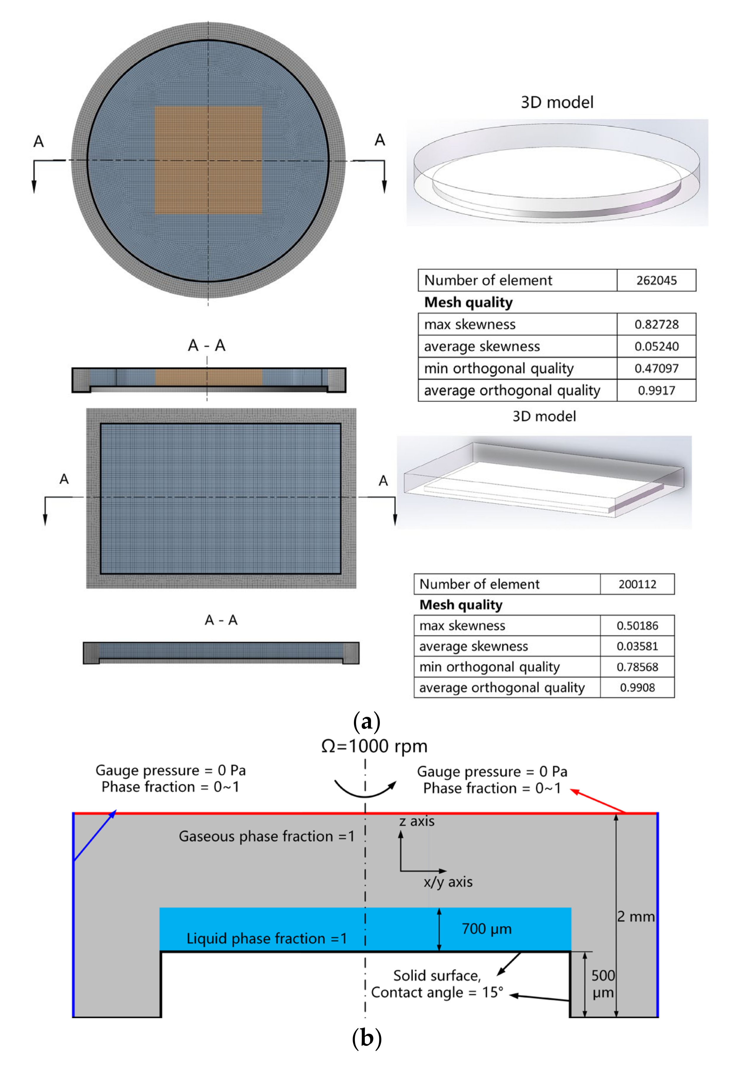
The influence of substrate shape film thickness in the central region of spin-coated films was studied. In the theoretical model proposed by Emslie, the film was supposed to be spin-coated on an infinite plate, and the influence of substrate geometry on the evolution of film thickness was not discussed. In this paper, the VOF model was used to establish a three-dimensional spin-coating numerical simulation model, and the influence of substrate shape on the evolution of film thickness in the spin-coating process was studied.
Different from the analytical model, the two-phase flow model was used in the numerical simulation to simulate the interaction between air and liquid. According to the results displayed in
Figure 4, the film thickness at different moments of the VOF model and the analytical model was compared. It can be concluded that when the solvent evaporation was ignored, the effect of the airflow on the film thickness thinning process during the spin-coating was very small. In addition, under the simulated conditions adopted in this paper (evaporation is not considered), the difference in film thickness between the rectangular substrate and circular substrate at each timepoint in the progress of spin-coating was very small ((
hr0 −
hc0)/
hc0 ≤ 2%), and the evolution rule of film thickness was almost the same. According to the simulation results, it could be concluded that the shape of the substrate had little effect on the evolution of the film thickness during the spin-coating process without considering the solvent evaporation.
To verify the influence of substrate shape on the evolution of film thickness, spin-coating experiments were carried out on rectangular and circular substrates at different rotating speeds 1000, 2000, 3000, 4000 and 5000 rpm. Three groups of experiments were conducted, and the results of the final film thickness at each rotational speed were shown in
Figure 5. The average film thickness of the central region was taken as the actual film thickness at this rotating speed, and the standard deviation of each set of data was taken as the error bar.
Table 2 showed the results that the film thickness on the rectangular substrate was larger than that of the circular substrate at all speeds. The difference in film thickness ranged from about 5% to 15% and it tended to increase with the rotating speed. This result was inconsistent with the conclusion that the evolution of the film thickness was independent of the shape of the substrate. Compared with the numerical simulation, there was solvent evaporation during the whole spin-coating experiment. Therefore, the solvent evaporation was supposed to be the dominant factor that affects the film thickness of substrates in different shapes, and further experiments were designed to clarify this conjecture.
Enough solvent was arranged in the spin coater chamber and the other parameters were the same as mentioned previously. The-spin coater chamber was sealed and kept still for 30 min to ensure the sufficient evaporation. It was supposed that the solvent evaporation was efficiently suppressed during the whole spin-coating process.
The film thickness results were obtained under different experimental conditions of solvent evaporation, as presented in
Figure 6. In general, the film thickness of rectangular substrate was larger than that of the circular substrate, which was caused by the different evaporation rates at the edge region. It was supposed that the evaporation rate at the edge region of rectangular substrate was larger than that of circular substrate. The film at the edge region was dried faster, and the liquid in the center region was impeded, which resulted in larger film thickness. The solvent could evaporate freely for Group A, but the solvent evaporation was suppressed for Group B with the help of the arrangement of abundant solvent around the substrate. At all rotation speeds, whether on a rectangular or circular substrate, the film thickness of group B was in the range of from 100 to 200 nm, which was smaller than that of group A. At the beginning of the spin-coating process, the radial outflow induced by centrifugal force was the dominant factor in the film thinning. Then, solvent evaporation became the leading factor when the film was thinned to a thinner thickness. At this stage, the concentration of gaseous solvent in the chamber could inhibit the solvent evaporation, which would result in a decrease in viscosity. The low viscosity of the solution would enhance the effect of the radial outflow, and more liquid was driven out of the substrate under the same centrifugal force, which would lead to the thinner film. Based on the results in
Table 2, the difference in the thickness of the film on the circular and rectangular substrate was significantly reduced, from 50−100 to 25–45 nm, under the condition of abundant solvent arrangement in the chamber. The difference ratio ((
hr−
hc)/
hc) was also significantly reduced under the same experimental conditions.
It was noted that even in the evaporation inhibition experiment, the difference in film thickness between the rectangular substrate and the circular substrate still existed, and the difference ratio increased with the increase in rotation speed. On the one hand, this was because the thickness of the film decreased with the increasing rotation speed. On the other hand, the experimental conditions could not ensure that the concentration of gaseous solvent in the spin-coating chamber was in a saturated state, and the evaporation rate of the solvent kept decreasing. In addition, the large rotating speed increased the air velocity on the surface of the film and promoted evaporation to a certain extent.
3.3. Distribution Characteristics of Film Thickness
The numerical simulation results of the spin-coating process on the substrates of two shapes were analyzed. The film thickness distribution was displayed in
Figure 7, and the same color bar was used to make the image clearer. The free interface of the liquid phase showed chaotic micro-features, in the form of irregular bumps and depressions. These micro-features were regarded as the random and disordered development of the two-phase interface. Except for the edge region, the film thickness distributions of the two shapes of substrates are similar. The film thickness of the central area on both substrates is reduced from about 700 to about 150 μm. For the edge region, the width of the edge bead region was about 1 mm and the height of the edge bead was about 250 μm on both circular and rectangular substrates.
The velocity characteristics of the airflow at 150 μm above the film was displayed in
Figure 8. The black frame inside is the rectangular substrate in the size of 24 mm × 15 mm. Within the inner black frame (above the substrate), the relative velocity of air gradually increased to 0.1 m/s, along with the radial position. The direction of airflow near the liquid film was approximately circular. Compared with
Figure 7a, it was concluded that the film’s distribution characteristics were not affected by the airflow field above the film. Therefore, the shear and wind resistance of airflow had little influence on film thickness and film thickness distribution with the conditions used in numerical simulation.
The experiment was carried out under the condition of multiple groups of rotating speeds, and the results were shown in
Figure 9. At a low rotating speed (1000–3000 rpm), the thickness of the film on the circular substrate decreased slightly along the radial direction (neglecting the edge bead effect), but this phenomenon became less obvious when the rotational speed was greater than 4000 rpm.
Figure 9d shows the film profile at the position of
y = 0 on the circular substrate and rectangular substrate. Under a low rotating speed (taking 1000 rpm as an example), the film thickness of the center region of the circular substrate decreased from 1354.2 to 1287.4 nm at the edge, and the film thickness on the rectangular substrate decreased from 1530.8 to 1422.2 nm at the edge. However, under a high rotating speed (5000 rpm), the decrease in film thickness along the radial direction was no longer obvious.
At a low rotating speed, the liquid film on the substrate was driven by a smaller centrifugal force. The liquid film near the center region flowed more slowly because of the smaller centrifugal force. Before the film was completely driven from the central region, the thin film at the edge of the substrate started to dry and this would impede the outflow of the liquid film from the central region. At this moment, the solvent kept evaporating, and finally, the film thickness decreased gradually along the radial direction. As for the spin-coating process at a higher rotating speed, a large amount of solution in the central region was driven out along the radial direction before the solution viscosity, which was induced by the solvent evaporation with a higher rotating speed, changed. For rectangular substrate, local low pressure near the edge caused by the Bernoulli effect resulted in the faster evaporation of the solvent. This would also impede the outflow of the liquid in the central region of the substrate. Therefore, the film thickness also gradually decreased along the radial direction.
Besides the radial film thickness characteristics, the film corner accumulation characteristics of the windward area on the rectangular substrate were more noticeable. According to the results, the corner accumulation characteristics are related to the airflow field. The experimental results did not agree well with the numerical simulation results. One of the reasons for this difference was that the solvent evaporation process was ignored in the numerical simulation work. The airflow action in the numerical simulation was not strong enough to have a significant influence on the film thickness distribution compared with the internal viscous force of the solution. Therefore, the uneven evaporation of the solvent was the dominant factor for the windward area of the rectangular substrate. The accumulation of the solution at the edge of the substrate and the relative vacuum promoted by the accumulation were the main reasons for the uneven evaporation of the solvent on the rectangular substrate.
The experiment was carried out under the condition of multiple groups of rotating speeds, and the results are shown in
Figure 9. At a low rotating speed (1000–3000 rpm), the thickness of the film on the circular substrate decreased slightly along the radial direction (neglecting the edge bead effect), but this phenomenon became less obvious when the rotational speed was greater than 4000 rpm.
Figure 9d shows the film profile at the position of
y = 0 on the circular substrate and rectangular substrate. Under a low rotating speed (taking 1000 rpm as an example), the film thickness of the center region of the circular substrate decreased from 1354.2 to 1287.4 nm at the edge, and the film thickness on the rectangular substrate decreased from 1530.8 to 1422.2 nm at the edge. However, under a high rotating speed (5000 rpm), the decrease in film thickness along the radial direction was no longer obvious.
At a low rotating speed, the liquid film on the substrate was driven by a smaller centrifugal force. The liquid film near the center region flowed more slowly because of the smaller centrifugal force. Before the film was completely driven from the central region, the thin film at the edge of the substrate started to dry, and this would impede the outflow of the liquid film from the central region. At this moment, the solvent kept evaporating and, finally, the film thickness gradually decreased along the radial direction. As for the spin-coating process at a higher rotating speed, a large amount of solution in the central region was driven out along the radial direction before the solution viscosity which was induced by the solvent evaporation with higher rotating speed changed. For rectangular substrate, the local low pressure near the edge, caused by the Bernoulli effect, resulted in the faster evaporation of the solvent. This would also impede the outflow of the liquid in the central region of the substrate. Therefore, the film thickness also gradually decreased along the radial direction.
Besides radial film thickness characteristics, the film corner accumulation characteristics of the windward area on the rectangular substrate were more noticeable. According to the results, the corner accumulation characteristics are related to the airflow field. The experimental results did not agree well with the numerical simulation results. One of the reasons for the difference was that the solvent evaporation process was ignored in the numerical simulation work. The airflow action in the numerical simulation was not strong enough to have a significant influence on the film thickness distribution compared with the internal viscous force of the solution. Therefore, the uneven evaporation of the solvent was the dominant factor for the windward area of the rectangular substrate. The accumulation of the solution at the edge of the substrate and the relative vacuum promoted by the accumulation were the main reasons for the uneven evaporation of the solvent on the rectangular substrate.
In
Figure 10, the velocity vector distributions of the film at 0.5 and 6 s were presented. The solution flowed along the edge at the later stage (
t = 6 s). However, both the radial flow rate of the solution and the centrifugal force were large in the early stage of the spin-coating process. The surface tension was small compared with the centrifugal force and had no significant effect on the film-spreading process. In the later stage of the spin-coating process, the radial outflow velocity of the liquid film decreased, and the mass of the film, as well as the centrifugal force, was very small. Therefore, the surface tension of the convex liquid surface at the edge could not be ignored at that stage.
According to the Young-Laplace equation:
where Δ
P is the pressure difference between the inside and outside of the liquid film,
γ is the surface tension coefficient, and
R1 and
R2 are the principal radii of curvature of the film interface.
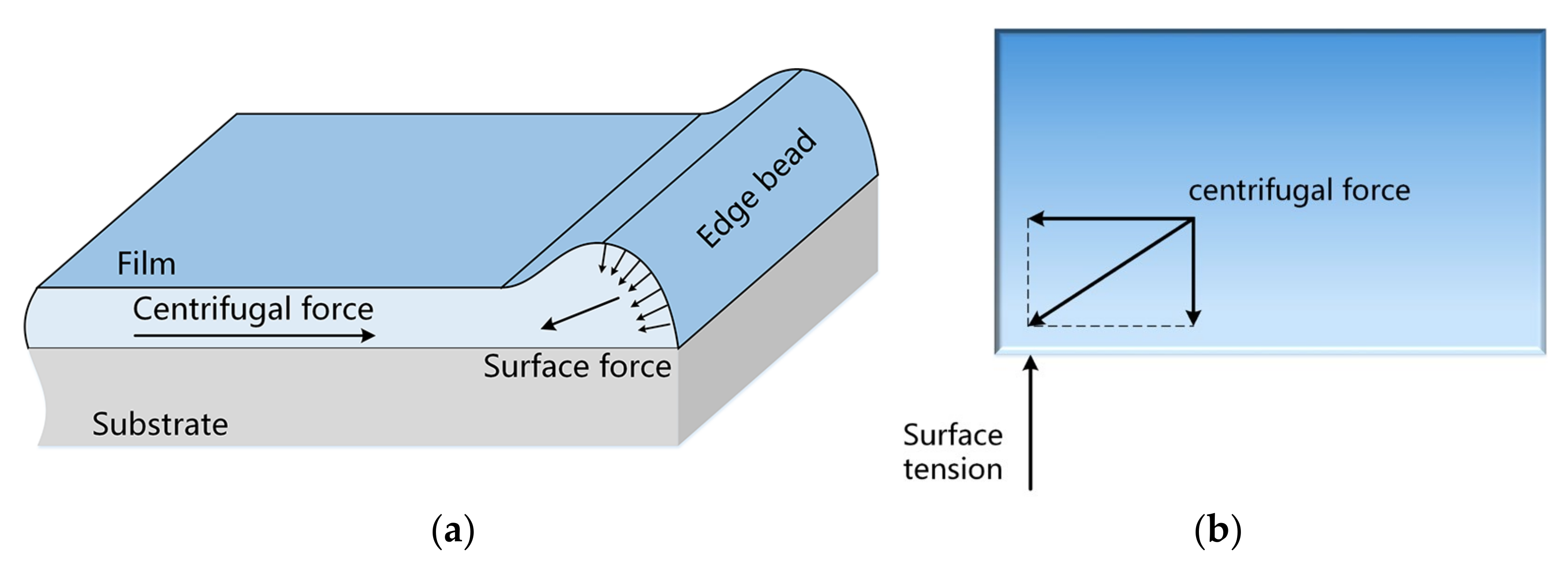
One of the best-known types of thickness unevenness is the “Edge Bead”, which appears as a thick ridge along the periphery of the substrate. The surface tension force schematic inside the “Edge Bead” is shown in
Figure 11. The projection of the surface tension force on the horizontal plane was perpendicular to the geometric edge of the substrate, which counteracted part of the centrifugal force. For this reason, the liquid film on the rectangular substrate flew along the edge and intensified the accumulation of solution at the edge of the substrate. The Bernoulli effect on the surface of the liquid film was promoted by the accumulation of the solution on the edge of the rectangular substrate, and the mechanism of the Bernoulli effect was explained in
Figure 12.
According to Bernoulli’s equation:
where
P is the pressure,
ρ is the density of air,
Z is the height, and
g is the acceleration of gravity. When the air streamline splits and flows through different paths, there will be differences in velocity. When the edge beads formed at the edge of the substrate, the airflow over the liquid film had a longer path, and the flow speed was relatively large. According to Equation (16), the pressure
Ptop above the liquid film is less than
P0, forming a relative vacuum and promoting the evaporation of the solvent. Therefore, a prominent edge-stacking feature of thin films is generated on rectangular substrates. Based on the above analysis, the differences in film geometry are mainly caused by the solvent nonuniform evaporation and the Bernoulli effect at the edge region.


