Article

Effect of Process Parameters and Layer Thickness on the Quality and Performance of Ti-6Al-4V Fabricated by Selective Laser Melting

1
School of Artificial Intelligence, Beijing Technology and Business University, Beijing 100048, China
2
Mechanical Industry Key Laboratory of Heavy Machine Tool Digital Design and Testing, Faculty of Materials and Manufacturing, Beijing University of Technology, Beijing 100124, China
*
Author to whom correspondence should be addressed.
Coatings 2021, 11(11), 1323; https://doi.org/10.3390/coatings11111323
Submission received: 30 September 2021 / Revised: 20 October 2021 / Accepted: 23 October 2021 / Published: 29 October 2021

Abstract

:
To improve the quality of thick powder bed and realize the matching of thick powder bed and thin powder bed in the later stage, the influence of process parameters for the single-track, multi-layer fabrication, relative density, surface quality, defect, remelting, and boundary optimization performance of different layer thicknesses of Ti-6Al-4V fabricated by selective laser melting were investigated. It is more conducive to the stable forming of single-track when the point distance is half the diameter of the laser beam, and the exposure time is appropriately extended. The thin powder bed needs the corresponding point distance and exposure time under the laser power of 280–380 W to obtain high-density specimens. The thick powder bed needs to be able to ensure the formation of high-quality specimens under the smaller point distance and longer exposure time under higher laser power of 380 W. Both thick powder bed and thin powder bed will cause un-melted defects between molten pools, spheroidization defects caused by splashing, and microporous defects. The remelting process can significantly improve the surface quality of the formed specimen, but the surface quality of the thick powder bed is worse than that of the thin powder bed. The boundary quality of thick powder bed is worse than that of thin powder bed, and the boundary shape has a greater influence on the quality of the SLM forming boundary. Different strategies should be adopted to form the boundary of different shapes. Increasing the boundary count and increasing the laser power are more conducive to the improvement of boundary quality.

1. Introduction

Selective laser melting (SLM) is an additive manufacturing technique that melts metal powder layers using a laser beam [1,2]. In industry, a thin layer of 20–50 μm is typically used in SLM forming to ensure the fabrication of metal products with excellent surface quality and mechanical qualities. The basic technique is to spread a thin layer of powder on a substrate and selectively melt the desired shape with a laser beam. Furthermore, the substrate is lowered to the thickness of the set layer, and a new layer of powder is applied. Then, repeat the melting process until a complete specimen is obtained [3]. Titanium-based alloy is an important non-ferrous metal. It has the advantages of low density, high specific strength, good corrosion resistance, low thermal expansion coefficient, good weldability, non-toxic and non-magnetic, etc. It is most commonly found in the aerospace, medicinal, and automotive industries [4,5]. Ti6Al4V is a challenging metal to produce, and traditional manufacturing methods make it even more difficult. SLM is capable of producing high-performance metal parts with the highest forming precision and quality [6].
Although the thin layer can achieve higher relative density and surface quality, it severely limits the efficiency of SLM forming. For example, Yadroitsev [7] et al. utilized 50 μm layer thickness forming specimens with a relative density of 96.72–99.93% but only 1.2 mm3/s forming efficiency. Qiu et al. [8] employed the Ti-6Al-4V specimen with a 20 μm layer thickness to achieve full density (99.9%) and high surface accuracy (Ra ≤ 15 µm), with a forming efficiency of only 0.45 mm3/s. He also discovered that combining high laser power with low powder layer thickness creates a broader processing window and allows for the production of specimens with low porosity (1%) within a given range. The porosity level and surface roughness rise as the powder layer thickness increases. To produce 316 L alloy components, Wang et al. [9] employed a layer thickness of 150 μm and raised the forming efficiency to 12 mm3/s. The compactness of 1Cr18Ni9Ti alloy specimens produced with layer thicknesses of 100 and 150 μm was shown to be lower by Ma et al. [10]. To produce Ti6Al4V specimens, Shi et al. utilized a layer thickness of 200 μm and a forming rate of 7.2 mm3/s [11].
To enhance forming efficiency, increasing layer thickness can minimize powder laying time and needed forming time [12]. However, as the layer thickness grows, the necessary laser energy density grows, necessitating an increase in laser power. When producing a thin powder bed, the laser’s intensity is visibly different from when forming a thick powder bed, and the intensity of the laser is considerably stronger when forming a thick powder bed. Furthermore, because of the high laser intensity, splashing and overheating of the liquid are common, resulting in internal defects and a rough surface quality [13]. The surrounding powder layer clings to the surface or side surface while SLM forming Ti6Al4V, increasing surface roughness [14]. The surface quality of SLM formed specimens is affected by a combination of process factors [15,16]. Different laser energy densities result in four different types of single tracks, according to Wang et al. [17]. According to Nguyen et al. [18], the density and dimensional accuracy of the manufactured specimens increase as the powder layer thickness decreases. Sufiiarov et al. [19] discovered that Inconel 718 prepared with a layer thickness of 30 μm had stronger strength and lower elongation than Inconel 718 prepared with a layer thickness of 50 μm. Optimizing process parameters, according to Maamoun et al. [20], can reduce the post-processing operations of SLM to prepare aluminum alloy.
The SLM forming process is affected by many factors, such as laser power, exposure time, point distance, hatch spacing, scanning strategy, forming environment, powder shape, etc. The SLM forming process undergoes complex physical changes. The powder is melted into a liquid state and then solidified into a solid state. The process involves energy absorption and transmission, microstructure evolution, melt flow and material evaporation, and other multi-field coupling phenomena [21,22]. Affected by the above process factors, defects, such as splashing, pores, spheroidization, and cracks, are easily formed. These defects are harmful to the mechanical and physical properties of manufactured parts, thereby limiting the application of SLM [23]. To increase the forming quality of specimens while maintaining high forming efficiency, more research into the effects of process parameters and layer thickness on forming quality is required. As a result, this article examines single-track characteristics, surface quality, cross-sectional characteristics, relative density, and the forming process to improve the surface and boundary quality of 50 μm (thin powder bed) and 150 μm (thick powder bed), as well as expose the defect producing mechanism.

2. Materials and Methods

2.1. Materials

In the experiment, the Ti-6Al-4V powder with a particle size of 15~53 μm provided by Falcontech (Wuxi, China) was used. The morphology of the powder is shown in Figure 1a under scanning electron microscopy (SEM) (Phenom XL, Phenom-World, Eindhoven, The Netherlands), and the average particle size calculated using ImageJ 1.5.0 software (NIH, Bethesda, MD, USA) shown in Figure 1b is 32 µm (D10: 16.4 µm, D90: 57.54 µm). The chemical composition of Ti-6Al-4V powder is shown in Table 1.

2.2. Experimental Setup and Manufacturing Process

For SLM experiments, a Renishaw AM400 (Renishaw plc, London, UK) was used. A continuous laser mode laser with a maximum laser power of 400 W and a laser beam diameter of 70 m is used in the AM400. To maintain the oxygen concentration below 80 ppm in all experiments, 99.99% percent high-purity argon was utilized as the protective gas in the enclosed room. The substrate for the experiment is a 20-mm-thick commercial Ti-6Al-4V alloy sheet. The single-track melting state experiments was performed first during the forming process. To test the process parameters, a single-track with a length of 20 mm is produced on the forming substrate. The process parameters were modified based on the single-track experiment, and varied laser power, point distance, exposure time, and hatch spacing were utilized to produce an 8 mm circular specimen using the cross-scan method. This work uses an interval scanning layer strategy to increase forming efficiency and evaluates different layer thicknesses of 50 and 150 μm on the same substrate. Table 2 shows the two sets of process parameters. To test the specimen’s forming quality, multi-layer SLM fabrication with a diameter of 8 mm was produced, according to the specifications indicated in Table 3, based on the findings of the single-track experiment. The samples with an inner circle diameter of 8 mm and an outside cube side length of 16 mm were also created to increase the forming surface quality and forming accuracy, as shown in Table 4.

2.3. Characterization

After SLM fabrication, the multi-layer fabrications were sectioned using wire cutting equipment (Cmne, Beijing, China), to observe the surface topography. Metallographic inlays were then fabricated, and their cross-sectional morphologies were observed after grinding and polishing. The metallographic sample was ground and polished according to the standard metallographic procedure and then corroded with a mixed kroll reagent of 2 mL HF, 6 mL HNO3, and 90 mL H2O. The surface morphology and cross-sectional morphology of the single-track and multilayer block specimens were characterized by a three-dimensional laser scanning microscope (VK-X200, KEYENC, Osaka, Japan). The Archimedes method was used to calculate the density of the formed specimens. ImageJ software (NIH, Bethesda, MD, USA) was used to quantify the cross-sectional morphology of the block specimen. The surface roughness of the formed parts was illuminated by a 3D laser scanning microscope (SZ-2000, ASI, UT, USA).

3. Results and Discussion

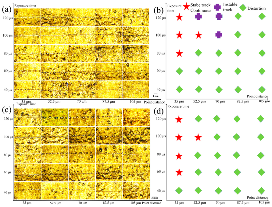
3.1. Single Track Experiments

The performance of SLM components is heavily influenced by the forming quality of the single-track. To assure the quality of the produced specimen, the single-track forming parameters are utilized to form the specimen. To screen process parameters and prepare for forming specimens, this part focuses on the use of high-efficiency forming technology (interval scanning layer strategy) and the forming quality of thin powder bed forming single-track. The surface morphology of the single-track and the impact of process factors were investigated using 50 and 150 μm to produce the single-track.
Figure 2 shows the surface morphologies and statistical results of the single-track of 50 and 150 μm formed under 300 W laser power. When the layer thickness is 50 μm, the results of using a 300 W power laser to form a single-track are shown in Figure 2a,b. When the exposure time is 40 μs, the single-track is almost completely distorted. This is because the time for melting the powder at a single location is too short, and the powder is not sufficiently melted. With the extension of the exposure time, the stable single-track gradually increased. This shows that the powder is irradiated by the laser beam for a suitable time, which is conducive to the full melting of the powder. When the point distance is less than the spot diameter (70 μm), appropriately increasing the exposure time is conducive to the stable forming of the single-track. When the point distance exceeds the spot diameter, properly increasing the exposure time cannot guarantee the stable forming of the single-track. Although, when the point distance is smaller than the spot diameter, increasing the exposure time is conducive to the stable forming of the single-track. However, the exposure time cannot be extended indefinitely. This is because the long-term exposure to metal powder (or liquid metal) is not conducive to the stability of the molten pool. When the layer thickness is 150 μm, the result of using 350 W power laser to form the single-track is shown in Figure 2c,d. When the exposure time is higher than 100 μs, it can ensure that the powder has enough time to melt, and the single-track can be formed. When the layer thickness is 150 μm, the amount of powder that needs to be melted for a single exposure point increases, so the laser energy density is more required. Increasing the point distance and shortening the exposure time will reduce the laser energy density of a single exposure point, so the single-track cannot be formed stably. A comprehensive comparison of 50 and 150 μm layer thicknesses shows that the exposure time required to increase the layer thickness is longer, and the point distance setting needs to be reduced to ensure stable formation of the single-track.
Figure 3 shows the surface map and statistical results of a single-track of 50 and 150 μm formed under 350 W laser power. When the layer thickness is 50 μm, the results of using a 350 W power laser to form a single-track are shown in Figure 3a,b. When the laser power is increased to 350 W, the stable single-track does not increase compared to 300 W. This is because the higher laser power is not conducive to the stability of the molten pool at a smaller layer thickness. As shown in Figure 3c,d, when the layer thickness is 150 μm, the stable forming of the melt channel can be ensured under the combination of a smaller point distance and a longer exposure time. Comparing Figure 2 and Figure 3, it can be found that the point distance setting of both large and low-layer thicknesses needs to be smaller than the diameter of the laser beam, and, when the point distance is set to half the diameter of the laser beam (35 μm), it is more conducive to single bead. The stable forming exposure time is a key parameter to ensure powder melting. High-layer thickness requires longer exposure time to fully melt the powder.

3.2. Multi-Layer SLM Fabrication

The formed specimen is the product of numerous process parameters being combined together. The process parameters are modified in this section based on single-track forming to produce the process parameter combination for producing high-density specimens. The cross-section forming quality and relative density were assessed by comparing 50 and 150 μm formed specimens.
Figure 4 shows the cross-sectional morphology and statistical results of 50 and 150 μm specimens produced with a 280 W laser power. Prolonging the exposure time as the point distance rises, as illustrated in Figure 4a,b, is favorable to generating high-density formed specimens. A high number of un-fused defects emerge when the point distance is increased. This is because increasing the point distance necessitates a higher laser energy density. The energy density is insufficient to totally melt the powder when the power or exposure time is not increased, thus the produced molten pool being smaller, and the smaller molten pool being between the molten pool and the molten pool. Because the overlap is not perfect, and there are more unfused flaws. When the point distance is 80 μm, there are a lot of un-fused flaws. This is consistent with the poor forming quality seen in the single-track experiments when the point distance is greater than the spot diameter. When the point distance is small (35–50 μm), extending the exposure time will result in the appearance of a limited number of micro-holes. This is due to the fact that, when the exposure duration is increased, the laser energy density increases. With a greater laser energy density, the molten pool may readily stay in a liquid state for an extended period of time, lowering the solubility of the gas until it is released too late to be removed from the liquid surface. The suitable parameters for a layer thickness of 50 μm when the laser power is 280 W are: the proper exposure time must be matched with the appropriate point distance to guarantee the stability of the energy density and the molten pool during the formation process. When the layer thickness is extended to 150 μm, the point distance must be less than half of the spot diameter (35 μm) to ensure superior forming quality, as illustrated in Figure 4a,b. The larger point distance will make high-quality forming with thick layers difficult. Prolonging the exposure time will be more favorable to getting high-density specimens since the powder layer is thicker, and the amount of powder is more.
Figure 5 shows a cross-sectional morphology and statistical results of 50 and 150 μm specimens produced with a 380 W laser power. As can be seen in the figure, a higher laser power makes it easier to assure high-quality forming of the specimen. Because the laser power is 380 W, the laser energy density is larger and the powder layer is thinner when the layer thickness is 50 μm. To share the laser energy density, increasing the point distance helps melt more powder under the same exposure point. The smaller point distance utilizes a shorter exposure time, while the bigger point distance uses a greater exposure time, as illustrated in Figure 5a,b, which is conducive to high-quality specimen forming. As illustrated in Figure, when the layer thickness is 150 μm, the thicker powder layer necessitates a smaller point distance and a longer exposure time to provide superior forming quality, as shown in Figure 5c,d. When the point distance is increased, more powder must be melted at the same exposure point, resulting in more pore flaws and even a significant number of un-fused defects in specimens formed under a shorter exposure time.
When the layer thickness is 50 μm, the laser power of 280–380 W is advantageous to the high-density forming of the specimens, but the corresponding point distance and exposure time are needed, as shown in Figure 4 and Figure 5. When the laser power is 280 W, the exposure time must be increased in proportion to the point distance. Excessive point distance and exposure time are not conducive to high-density specimen forming. The larger point distance and longer exposure time are more favorable to the form of the specimen when the laser power is 380 W, but the smaller point distance and longer exposure time are not. When the layer thickness is 150 μm, a greater laser power of 380 W is more favorable to specimen forming, and a smaller point distance and longer exposure time are required to assure the forming of high-quality specimens. The high-density forming of thick powder bed specimens is not aided by increasing the point distance.

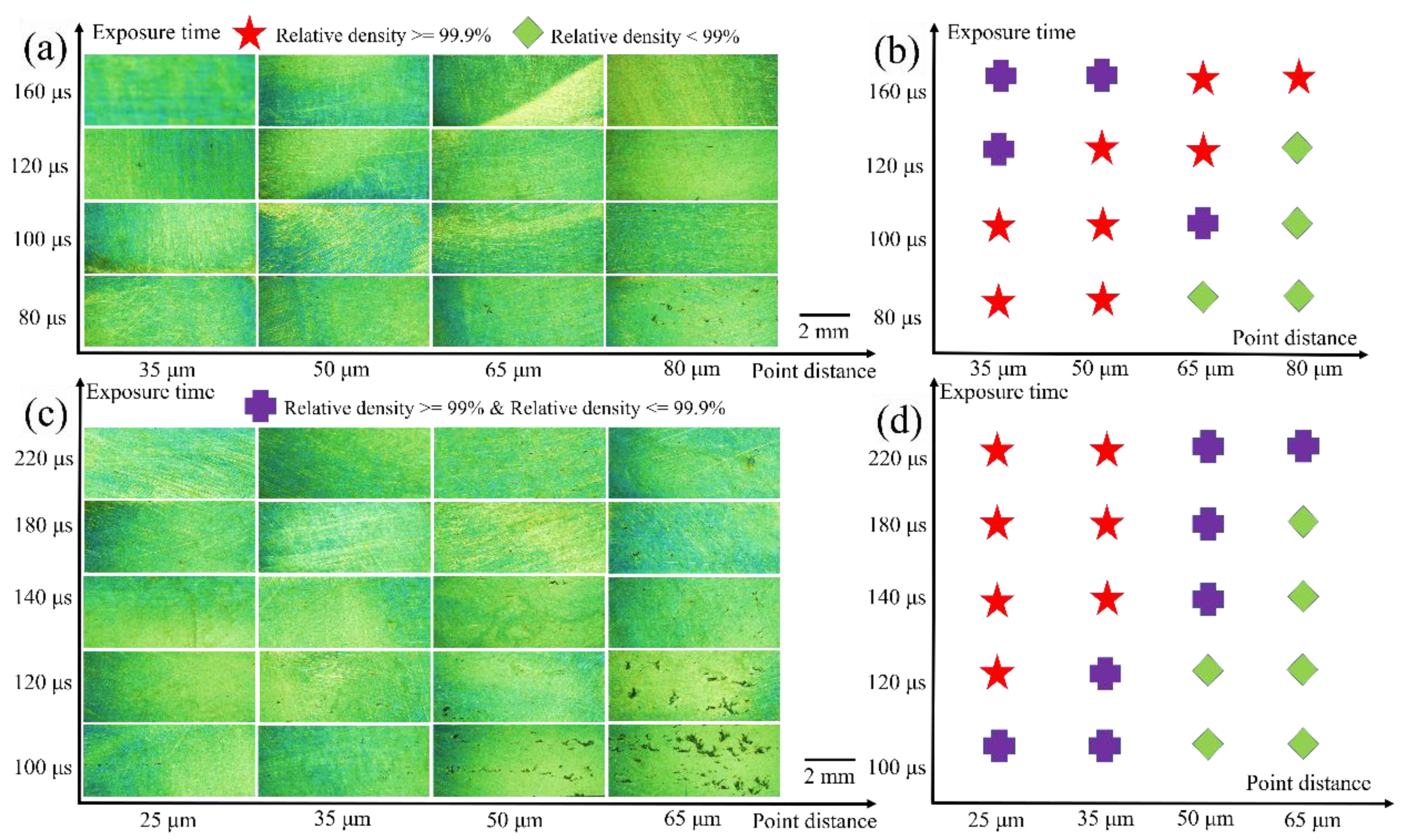
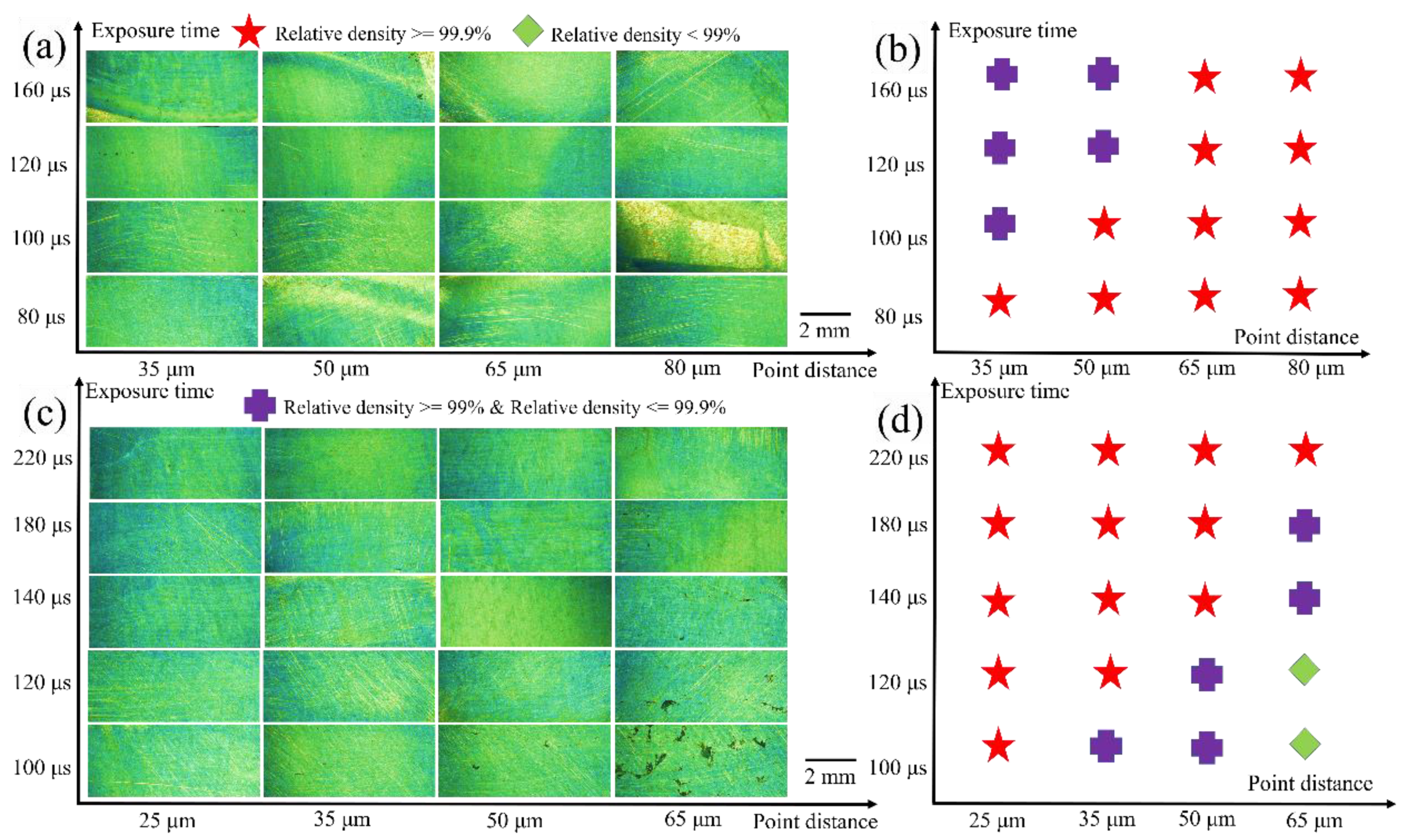
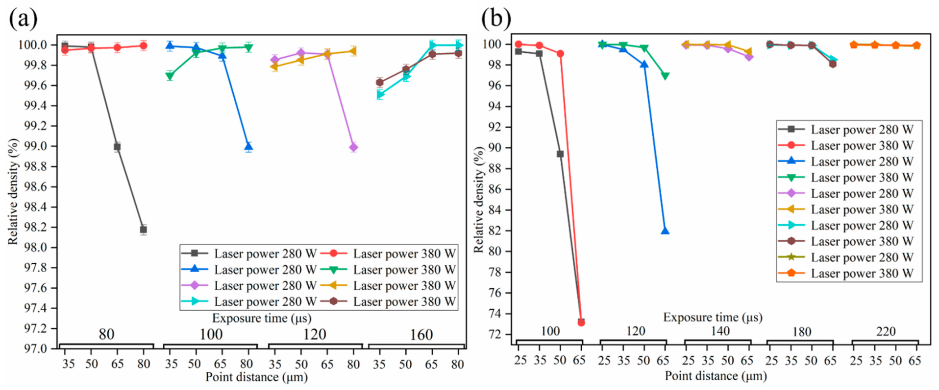
3.3. The Influence of Process Parameters on Relative Density

The forming parameter region of high-quality formed specimens may be observed by comparing the quality of formed specimens under different laser powers. This section examines the impact of process factors on the relative density of specimens.
Figure 6a displays the effect of various process parameters on the relative density of formed specimens with a layer thickness of 50 μm. The relative density drops as the point distance increases when the laser power is 280 W and the exposure time is 80–120 μs. This is because as the point distance grows, so does the quantity of powder required to melt a single exposure point, resulting in un-melted flaws and a decreased energy density. When the exposure time is raised to 160 μs, the relative density rises as the point distance is increased. This is due to the fact that the quantity of powder that can be melted rises as the exposure time increases, and the amount of powder that can be melted increases as the point distance increases, ensuring the proper energy density while melting the powder. The total forming density is greater when the laser power is 380 W. With the increase in point distance, the density rises. This is due to the fact that the higher the energy density at a given exposure point, the more likely it is to produce phenomena, such as powder evaporation. As a result, increasing the point distance promotes the spread of the laser energy density of a single exposure point, resulting in increased relative density. Figure 6b depicts the effect of various process parameters on the relative density of formed specimens with a thickness of 150 μm. Extending the exposure time to more than 140 μs is advantageous to the entire melting of the powder and, therefore, the rise in relative density. As can be seen in Figure 6b, the overall relative density drops as the point distance increases. This is because, with a greater point, distance will result in more molten powder being produced with the same laser energy density. Because the quantity of powder that can be melted down is limited, increasing the point distance at a thick layer thickness will almost certainly result in unfused flaws. When comparing Figure 6a,b, it is clear that, when a thick powder layer is utilized for forming, a smaller point distance may assure forming quality. When using a thin powder bed, a variety of process factors must be carefully examined. When using a thick powder bed or a longer exposure time, the point distance must be increased to improve the specimen’s forming quality. Compared with the previous research results of thin powder bed, the relative density of both the thin powder bed and the thick powder bed used in this study reached 99.99%, as shown in Table 5.

3.4. Research on Defects

The compactness of the formed specimen is generally poorer due to the presence of defects. As a result, it is critical to comprehend the fundamental mechanism of defect formation.
Defects are unavoidable in the SLM forming process since it is extremely complex solidification and cooling processes [26]. Figure 7a–c depicts three types of defects created by a 50 μm layer thickness, whereas Figure 7d–f depicts three types of defects induced by a 150 μm layer thickness. Un-melted between molten pools, spheroidization defects produced by splashing, and microporous defects are the three types of defects. The major issue impacting relative density is the defect of un-melted between the molten pools, which is produced by inadequate molten pool bonding. When the point distance or hatch spacing is set too big, un-melted between the molten pools appear. As illustrated in Figure 4 and Figure 5, this defect may be fully removed by decreasing the point distance or hatch spacing. The spheroidization defect is present inside the specimen, owing to the fact that the laser irradiates the powder, causing the condensate to splatter on the specimen’s surface. The laser wraps the condensate into the molten pool and induces spheroidization inside the specimen when it is transported to the next forming. External variables, such as inert flowing gas and hollow powder, produce microporous flaws. Adjusting process settings to remove microporous defects is challenging. The relative density of the formed specimen is strongly affected by the huge size of un-melted defects between the molten pools; however, these defects may be removed by changing the process parameters, but micropores and spheroidization defects are difficult to completely eradicate.

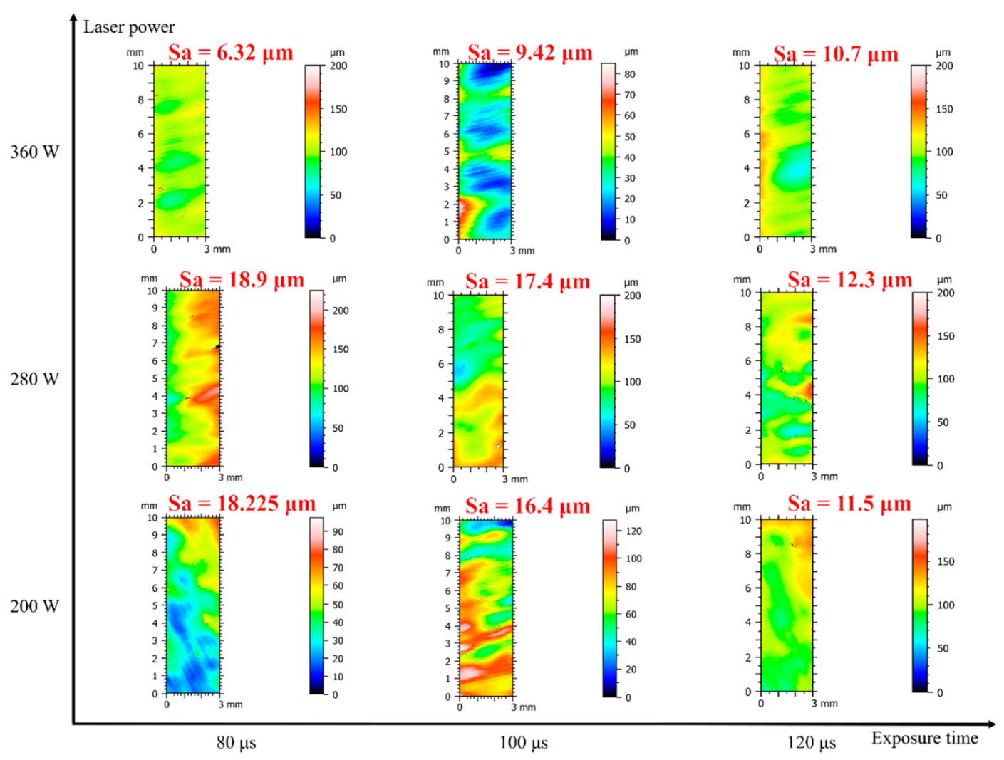
3.5. Research on Improvement of Surface Quality

During the SLM forming process, the layer thickness has a significant impact on the surface roughness of the formed specimens. This section focuses on reducing surface roughness and improving the surface quality of SLM formed specimens with various layer thicknesses. The roughness values of the four regions are gathered by measuring the roughness of the area outside the circle to the inside of the square, and the corresponding roughness data is acquired, since the formed specimen has an inner circle diameter of 8 mm and an outside square side length of 16 mm. To represent the roughness value of the complete formed specimen, the roughness values of the four regions are summed and averaged. Because of the varied forming locations, the values of the four areas may display different surface quality and roughness values, as illustrated in Figure 8.
Figure 9 shows the quality of the upper surface layer of the 50 μm layer thickness specimen after remelting it under various process settings. As demonstrated in Figure 9, the surface roughness decreases as the exposure time rises, and the surface quality improves. The surface roughness value is lowest when the laser power is 360 W. This might because remelting involves remelting the hardened specimen after the powder has melted and formed. The solidified specimen is a solid piece when compared to powder. Because the volume melted by a single exposure point is greater than the volume of the powder, a higher energy density is needed. More energy density may be given when more power is employed. As a result, remelting the produced portion and then forming a flat specimen is advantageous. Furthermore, the roughness value of the 200 W laser power is lower than the 280 W laser power. This might be due to the fact that the 200 W laser power is insufficient to penetrate the solidified specimen entirely, yet it can still remelt the generated surface spatter and other flaws to lower the degree of surface roughness. Because of the 280 W laser power, the solidified specimen may be stuck between penetration and non-penetration, resulting in poor surface quality.
Figure 10 shows the quality of the upper surface layer of the 150 μm layer thickness specimen after remelting it under various process settings. The surface quality of the high-layer thickness after remelting is worse, as shown in the figure, and the layer thickness difference is mostly due to the fact that, when the layer thickness is thick, more laser power or a longer exposure time are necessary to completely melt the surface. Because a thick powder layer can readily induce process instability, resulting in melt disturbance and splashing during the forming process, achieving a higher surface quality effect during the forming process is challenging. Despite this, the laser intensity and exposure time have a significant impact on surface quality. Increasing the power and exposure time, as with the thin powder bed, is more favorable to enhancing the surface quality. The surface roughness decreases as the laser power increases, indicating that the surface quality is steadily improving. At the same time, the produced specimen has the lowest surface roughness when the laser power is 380 W, and the exposure time is 220 μs. This demonstrates that, in order to get the best laser energy density, it is still important to evaluate the whole impact of laser power and exposure time on the surface quality of the produced specimen while creating a thick powder bed. The surface roughness of the specimens formed at 50 and 150 µm layer thicknesses in this study ranged from 6.32 to 18.9 µm and from 18.7 to 60.8 µm, respectively. The surface roughness of the specimen after remelting can almost reach the specimen (Ra = 10–15 µm) prepared with a thin layer thickness (20–60 µm) in the literature [8,27,28,29]. Compared with the thick powder layer (Ra = 45–166 µm) [26] in the previous study, this study can reduce the surface roughness to 18.7 µm.

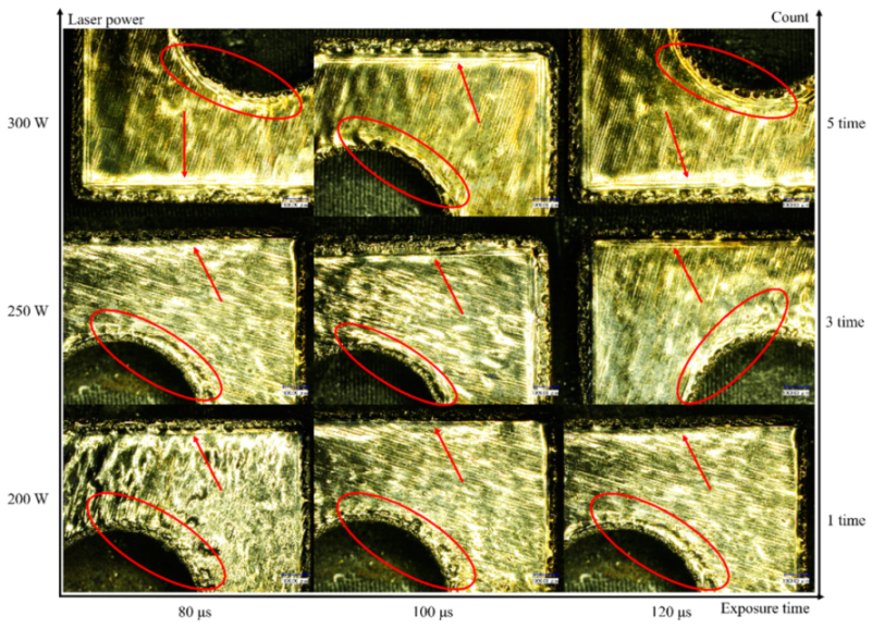
3.6. Research on Border Strategy

SLM can use a flexible forming approach based on the interval scanning layer strategy. The upper surface, inner core, and contour of the SLM developing specimen are partitioned, and various forming techniques are utilized for each partition. The careful sculpting of the contour can assure the quality of the formed specimen and make further processing easier.
It is impossible to prevent the phenomena of boundary powder adhering during SLM formation. If the boundary solidification is inadequate, it will result in more significant boundary powder sticking, which will make further processing and the assurance of dimension accuracy more difficult. With a layer thickness of 50 μm, Figure 11 depicts the developing boundary quality of several boundary methods. The figure indicates that, as the laser power grows, the boundary forming melt channel becomes more continuous and stable, and the forming quality improves, indicating that high laser power is advantageous to the solidification of the boundary. When the laser power is limited (200 W), lengthening the exposure time can still enhance the fixed quality of the border. Furthermore, the figure shows that, when the laser power is 200 W, the forming quality of the circular and square borders are not same. The circular border is difficult to create, while the square border is easier. Both circular and square borders are best healed when the laser power is 250–300 W. Because the border gets clearer as the boundary count rises, raising the boundary count makes it easier to construct the specimen precisely. In conclusion, more laser power is better for improving boundary quality.
With a layer thickness of 150 μm, Figure 12 depicts the developing border quality of several boundary methods. When comparing Figure 11 and Figure 12, the boundary quality of 150 μm is determined to be worse than that of 50 μm. Because the powder layer is thicker at this point, the laser absorbs more external powder as the border solidifies, resulting in a boundary bump. The generated boundary melt channel is unstable when the laser power is 200 W. The boundary formation quality improves when the laser power is increased to 250 W. The border bump is more severe when the laser power is 300 W. Furthermore, the shape of the boundary has a bigger influence on the quality of the SLM creating border, and different techniques should be employed to generate different forms of boundaries.

4. Conclusions

This experiment studied the optimal forming process of Ti6Al4V fabricated by SLM. The relative density, defects, surface quality, and boundary properties of the thin powder bed and thick powder bed prepared specimens were analyzed. The main conclusions are as follows:
  • The point distance is smaller than the diameter of the laser beam, which is conducive to the stable forming of the single track. The thin powder bed needs to increase the exposure time to facilitate the stable formation of the melt, but the thick powder bed requires a longer exposure time to completely melt the powder.
  • The thin powder bed can be formed into high-density specimens under the influence of 280–380 W laser power and proper point distance and exposure time. The thick powder bed can be formed high-quality specimen with a laser power of 380 W, a smaller point distance, and a longer exposure time.
  • Un-melted defects between molten pools, spheroidization defects and microporous defects can occur in both thin powder bed and thick powder bed. By adjusting the process parameters, the specimen with almost full density can be obtained.
  • Increasing the power and increasing the exposure time are beneficial to the improvement of the surface quality of the two powder beds. The shape of the boundary has a great influence on the quality of the SLM forming boundary, and different strategies should be adopted to form the boundary of different shapes. Increasing the number of boundaries is more conducive to the accurate forming of the specimen.

Author Contributions

Conceptualization, Y.J. and P.W.; methodology, Y.J.; software, P.W.; validation, Y.J., P.W. and X.Y.; formal analysis, P.W.; investigation, Y.J.; resources, Y.J.; data curation, X.Y.; writing—original draft preparation, Y.J.; writing—review and editing, Y.J.; visualization, X.Y.; supervision, X.Y.; project administration, Y.J. All authors have read and agreed to the published version of the manuscript.

Funding

This work has been supported by the National Natural Science Foundation of China (Grant No 51975006).

Institutional Review Board Statement

Not applicable.

Informed Consent Statement

Not applicable.

Data Availability Statement

Data sharing not applicable.

Conflicts of Interest

The authors declare no conflict of interest.

References

  1. Todd, I. Metallurgy. No more tears for metal 3D printing. Nature 2017, 549, 342–343. [Google Scholar] [CrossRef] [PubMed] [Green Version]
  2. Shipley, H.; McDonnell, D.; Culleton, M.; Coull, R.; Lupoi, R.; O’Donnell, G.; Trimble, D. Optimisation of process parameters to address fundamental challenges during selective laser melting of Ti-6Al-4V: A review. Int. J. Mach. Tool Manuf. 2018, 128, 1–20. [Google Scholar] [CrossRef]
  3. Li, S.; Hassanin, H.; Attallah, M.M.; Adkins, N.J.; Essa, K. The development of TiNi-based negative Poisson’s ratio structure using selective laser melting. Acta Mater. 2016, 105, 75–83. [Google Scholar] [CrossRef] [Green Version]
  4. Najmon, J.C.; Raeisi, S.; Tovar, A. Review of additive manufacturing technologies and applications in the aerospace industry. In Additive Manufacturing for the Aerospace Industry; Froes, F., Boyer, R., Eds.; Elsevier: Amsterdam, The Netherlands, 2019; pp. 7–31. [Google Scholar]
  5. Xu, W.; Lui, E.W.; Pateras, A.; Qian, M.; Brandt, M. In situ tailoring microstructure in additively manufactured Ti–6Al–4V for superior mechanical performance. Acta Mater. 2017, 125, 390–400. [Google Scholar] [CrossRef]
  6. Gao, W.; Zhang, Y.; Ramanujan, D.; Ramani, K.; Chen, Y.; Williams, C.B.; Wang, C.C.; Shin, Y.C.; Zhang, S.; Zavattieri, P.D. The status, challenges, and future of additive manufacturing in engineering. Comput.-Aided Des. 2015, 69, 65–89. [Google Scholar] [CrossRef]
  7. Yadroitsev, I.; Smurov, I. Selective laser melting technology: From the single laser melted track stability to 3d parts of complex shape. Phys. Procedia 2010, 5, 551–560. [Google Scholar] [CrossRef] [Green Version]
  8. Qiu, C.; Panwisawas, C.; Ward, M.; Basoalto, H.C.; Brooks, J.W. On the role of melt flow into the surface structure and porosity development during selective laser melting. Acta Mater. 2015, 96, 72–79. [Google Scholar] [CrossRef] [Green Version]
  9. Wang, S.; Liu, Y.; Shi, W.; Qi, B.; Yang, J.; Zhang, F.; Han, D.; Ma, Y. Research on high layer thickness fabricated of 316L by selective laser melting. Materials 2017, 10, 1055. [Google Scholar] [CrossRef] [Green Version]
  10. Ma, M.; Wang, Z.; Gao, M.; Zeng, X. Layer thickness dependence of performance in high-power selective laser melting of 1Cr18Ni9Ti stainless steel. Mater. Process. Tech. 2015, 215, 142–150. [Google Scholar] [CrossRef]
  11. Shi, X.; Ma, S.; Liu, C.; Chen, C.; Wu, Q.; Chen, X.; Lu, J. Performance of high layer thickness in selective laser melting of Ti6Al4V. Materials 2016, 9, 975. [Google Scholar] [CrossRef] [Green Version]
  12. Li, F.; Wang, Z.; Zeng, X. Microstructures and mechanical properties of Ti6Al4V alloy fabricated by multi-laser beam selective laser melting. Mater. Lett. 2017, 199, 79–83. [Google Scholar] [CrossRef]
  13. Wang, D.; Wu, S.; Fu, F.; Mai, S.; Yang, Y.; Liu, Y.; Song, C. Mechanisms and char-acteristics of spatter generation in SLM processing and its effect on the properties. Mater. Des. 2017, 117, 121–130. [Google Scholar] [CrossRef]
  14. Safdar, A.; He, H.Z.; Wei, L.Y.; Snis, A.; de Paz, L.E.C. Effect of process parameters settings and thickness on surface roughness of EBM produced Ti-6Al-4V. Rapid Prototyp. J. 2012, 18, 401–408. [Google Scholar] [CrossRef]
  15. Yadroitsev, I.; Smurov, I. Surface morphology in selective laser melting of metal powders. Phys. Procedia 2011, 1, 264–270. [Google Scholar] [CrossRef] [Green Version]
  16. Rehme, O.; Emmelmann, C. Reproducibility for properties of selective laser melting products. In Proceedings of the Third International WLT-Conference on Lasers in Manufacturing, Munich, Germany, 13–16 June 2005; pp. 1–6. [Google Scholar]
  17. Di, W.; Yongqiang, Y.; Xubin, S.; Yonghua, C. Study on energy input and its influences on single-track, multi-track, and multi-layer in SLM. Int. J. Adv. Manuf. Technol. 2012, 58, 1189–1199. [Google Scholar] [CrossRef]
  18. Nguyen, Q.B.; Luu, D.N.; Nai, S.M.L.; Zhu, Z.; Chen, Z.; Wei, J. The role of powder layer thickness on the quality of SLM printed parts. Arch. Civ. Mech. Eng. 2018, 18, 948–955. [Google Scholar] [CrossRef]
  19. Sufiiarov, V.S.; Popovich, A.A.; Borisov, E.V.; Polozov, I.A.; Masaylo, D.V.; Orlov, A.V. The effect of layer thickness at selective laser melting. Procedia Eng. 2017, 174, 126–134. [Google Scholar] [CrossRef]
  20. Maamoun, A.H.; Xue, Y.F.; Elbestawi, M.A.; Veldhius, S.C. Effect of selective laser melting process parameters on the quality of Al alloy parts: Powder characterization, density, surface roughness, and dimensional accuracy. Materials 2018, 11, 2343. [Google Scholar] [CrossRef] [PubMed] [Green Version]
  21. Xu, W.; Sun, S.; Elambasseril, J.; Liu, Q.; Brandt, M.; Qian, M. Ti6Al4 V additively manufactured by selective laser melting with superior mechanical properties. JOM 2015, 67, 668–673. [Google Scholar] [CrossRef]
  22. Zhang, X.B.; Dang, X.A.; Yang, L.Y. Study on balling phenomena in selective laser melting. Laser Optoelectron. Prog. 2014, 6, 131–136. [Google Scholar]
  23. Zhang, B.; Li, Y.; Bai, Q. Defect formation mechanisms in selective laser melting: A review. Chin. J. Mech. Eng. 2017, 30, 515–527. [Google Scholar] [CrossRef] [Green Version]
  24. Kamath, C.; El-dasher, B.; Gallegos, G.F.; King, W.E.; Sisto, A. Density of additively-manufactured, 316L ss parts using laser powder-bed fusion at powers up to 400 w. Int. J. Adv. Manuf. Technol. 2013, 74, 65–78. [Google Scholar] [CrossRef] [Green Version]
  25. Dadbakhsh, S.; Hao, L.; Sewell, N. Effect of selective laser melting layout on the quality of stainless steel parts. Rapid Prototyp. J. 2012, 18, 241–249. [Google Scholar] [CrossRef]
  26. Shi, X.; Yan, C.; Feng, W.; Zhang, Y.; Leng, Z. Effect of high layer thickness on surface quality and defect behavior of Ti-6Al-4V fabricated by selective laser melting. Opt. Laser Technol. 2020, 132, 106471. [Google Scholar] [CrossRef]
  27. Milton, S.; Morandeau, A.; Chalon, F.; Leroy, R. Influence of finish machining on the surface integrity of Ti6Al4V produced by Selective Laser Melting. Procedia CIRP 2016, 45, 127–130. [Google Scholar] [CrossRef] [Green Version]
  28. Vaithilingam, J.; Prina, E.; Ruth, D.G.; Goodridge, R.D.; Hague, R.J.; Edmondson, S.; Rose, F.R.; Christie, S.D. Surface chemistry ofTi6Al4V components fabricated using selective laser melting for biomedical applications. Mat. Sci. Eng. C 2016, 67, 294–303. [Google Scholar] [CrossRef] [Green Version]
  29. Yan, X.L.; Xu, X.S. Method for accurately measuring of acoustic time difference based on optimal threshold. Measurement 2021, 171, 108769. [Google Scholar] [CrossRef]
Figure 1. Powder (a) morphology of TiAl alloy; (b) particle size distribution of TiAl alloy.
Coatings 11 01323 g001
Figure 2. The single-track experiments (a) surface morphologies with a power of 300 W and a layer thickness of 50 μm; (b) process results of (a); (c) surface morphologies with a power of 300 W and a layer thickness of 150 μm; (d) process results of (c).
Coatings 11 01323 g002
Figure 3. The single-track experiments (a) surface morphologies with a power of 350 W and a layer thickness of 50 μm; (b) process results of (a); (c) surface morphologies with a power of 350 W and a layer thickness of 150 μm; (d) process results of (c).
Coatings 11 01323 g003
Figure 4. Specimen formed with 280 W laser power (a) the cross-sectional morphology of the specimen under the layer thickness of 50 μm; (b) statistical results of (a); the cross-sectional morphology of the specimen under the layer thickness of 150 μm; (d) statistical results of (c).
Coatings 11 01323 g004
Figure 5. Specimen formed with 380 W laser power (a) the cross-sectional morphology of the specimen under the layer thickness of 50 μm; (b) statistical results of (a); the cross-sectional morphology of the specimen under the layer thickness of 150 μm; (d) statistical results of (c).
Coatings 11 01323 g005
Figure 6. Relative density curve: (a) 50 μm; (b) 150 μm.
Coatings 11 01323 g006
Figure 7. Internal defects of formed specimens: 50 μm: (a) un-melted, (b) porosity, (c) splash; 150 μm: (d) un-melted, (e) porosity, (f) splash.
Coatings 11 01323 g007
Figure 8. Schematic diagram of specimen roughness partition.
Coatings 11 01323 g008
Figure 9. The surface roughness of the specimen under different parameters of 50 μm layer thickness.
Coatings 11 01323 g009
Figure 10. Surface roughness of specimens under different parameters of 150 μm layer thickness.
Coatings 11 01323 g010
Figure 11. Forming boundary quality of different boundary strategies under 50 μm layer thickness.
Coatings 11 01323 g011
Figure 12. Forming quality with different boundary strategies under 150 μm layer thickness.
Coatings 11 01323 g012
Table 1. Chemical composition of Ti-6Al-4V powder used in the experiments.
ElementTiFeCONHAlV
Content (wt. %)Balance0.0280.0230.06340.00260.0026.234.09
Table 2. The process parameters of the single-track experiments.
ParameterValueIncrement
Laser Power (W)300–35050
Layer thickness (μm)50–150100
Exposure time (μs)40–12020
Point distance (μm)35–10517.5
Table 3. The process parameters of the different specimens.
ParameterValueIncrement
Laser Power (W)280–380100
Layer thickness (μm)50–150100
Exposure time (μs)80–160/100–22020–40
Point distance (μm)35–80/25–6515/10–15
Hatch spacing (μm)70--
Table 4. The process parameters to improve the forming quality.
ParameterValueIncrement
Laser Power (W)200–380-
Layer thickness (μm)50–150100
Exposure time (μs)80–120/200–24020
Point distance (μm)35-
Hatch spacing (μm)70-
Table 5. Summary of different layer thickness in previous studies.
Layer Thickness (μm)Relative Density (%)References
3099.00[24]
5099.93[7]
5099.99In this research
8099.80[10]
10098.5[25]
15099.99In this research
Publisher’s Note: MDPI stays neutral with regard to jurisdictional claims in published maps and institutional affiliations.

