
Assessment of the Condition of Anilox Rollers


Abstract
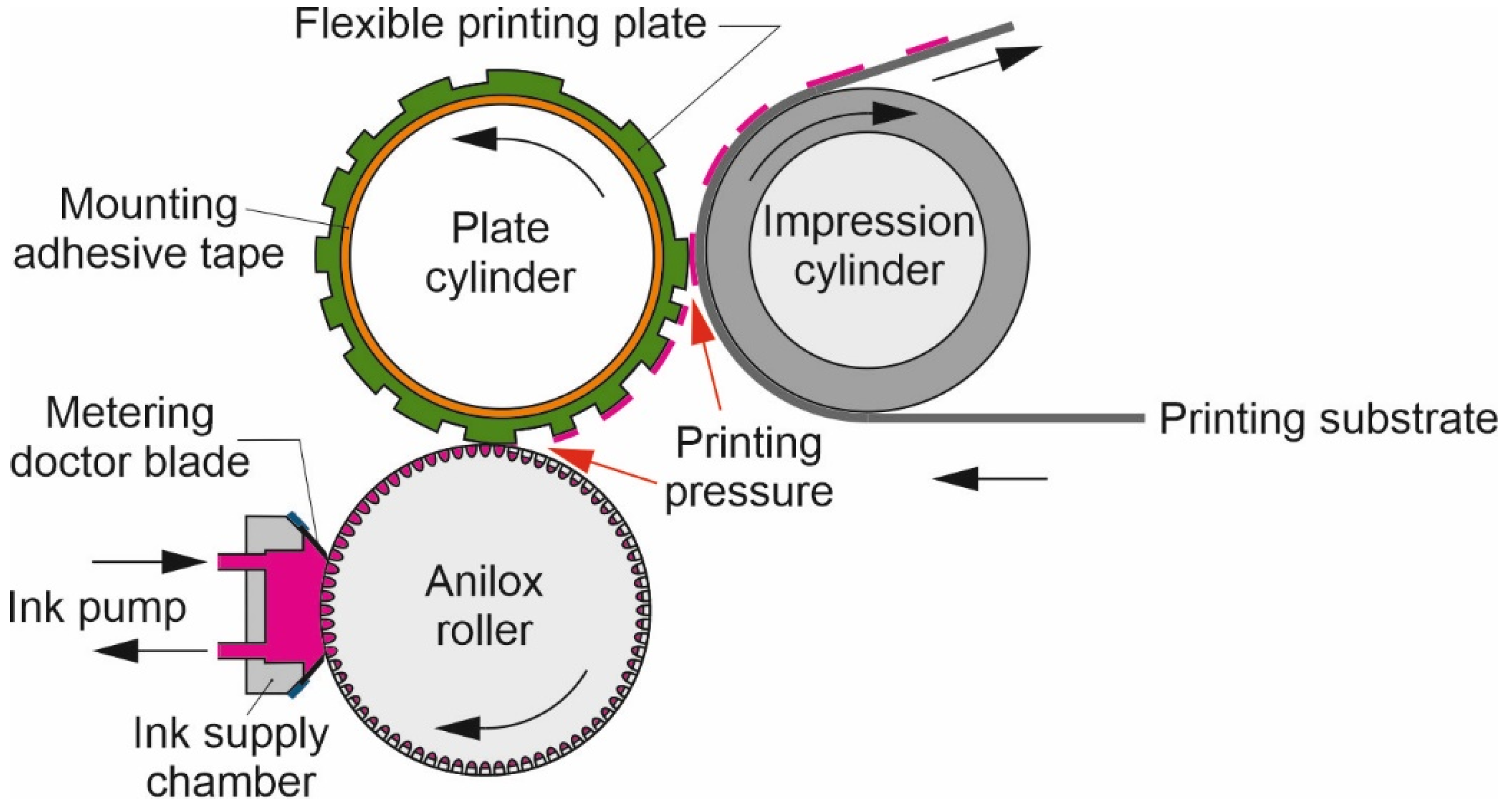
:1. Introduction
2. Materials and Methods
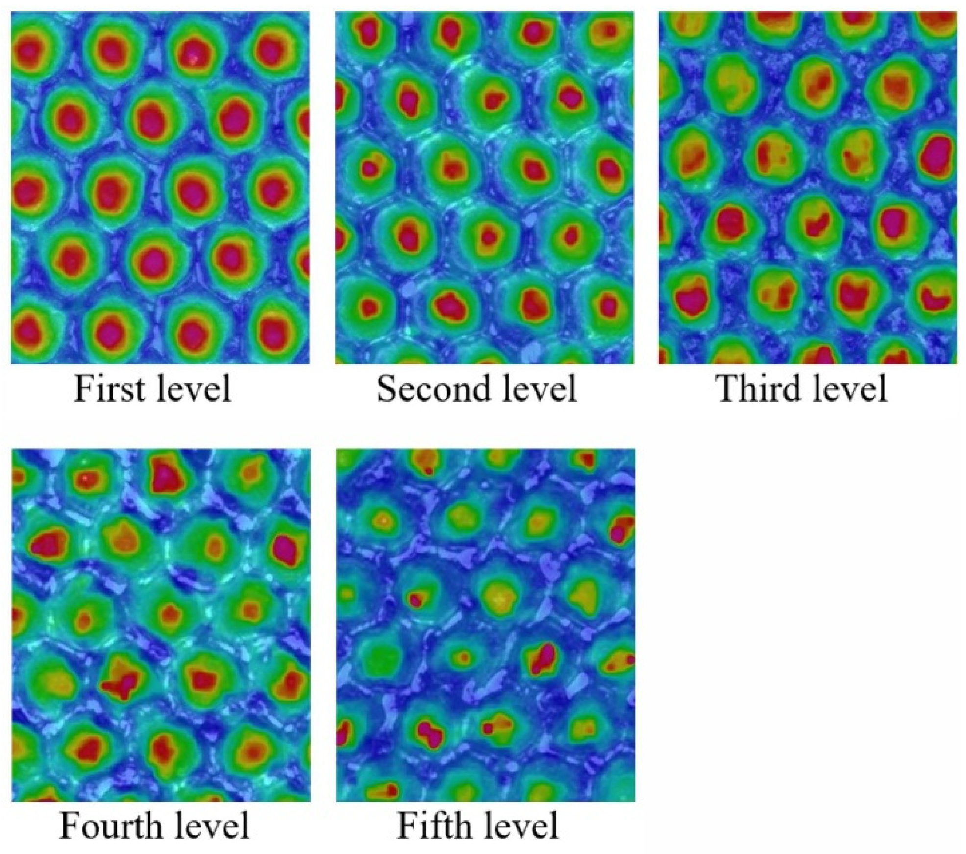
2.1. Evaluation of Anilox Roller Cell Clogging
2.2. Evaluation of the Amount of Transferred Ink
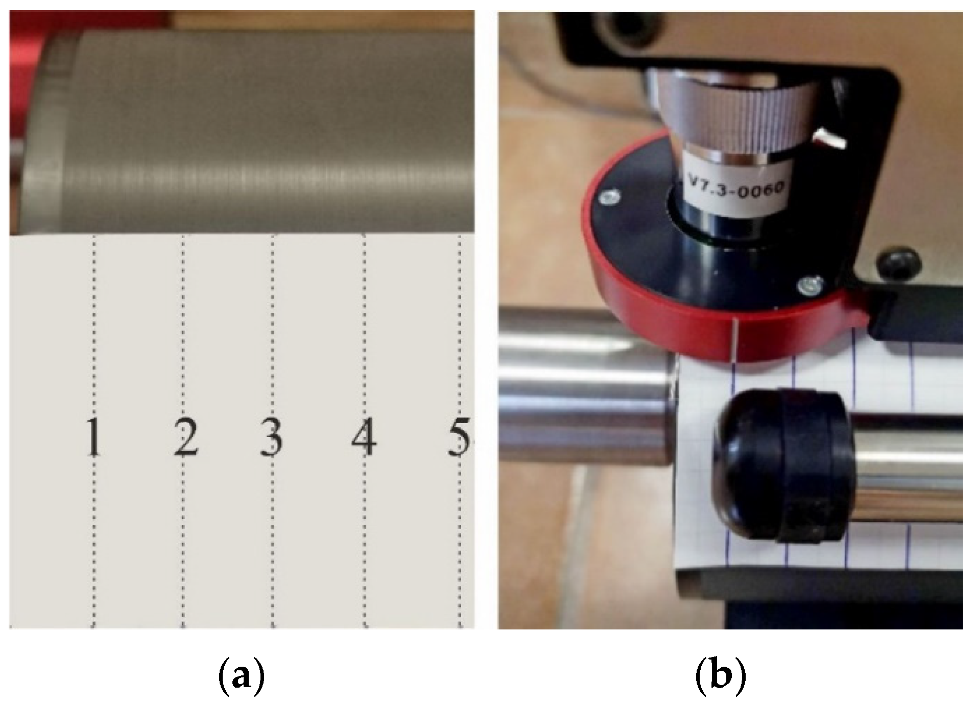
2.3. Evaluation of Surface Wear of Anilox Rollers
3. Results and Discussion
3.1. Results of Anilox Roller Ink Transfer Measurement and Clogging Assessment
3.2. Dependence of Clogging on Cell Size
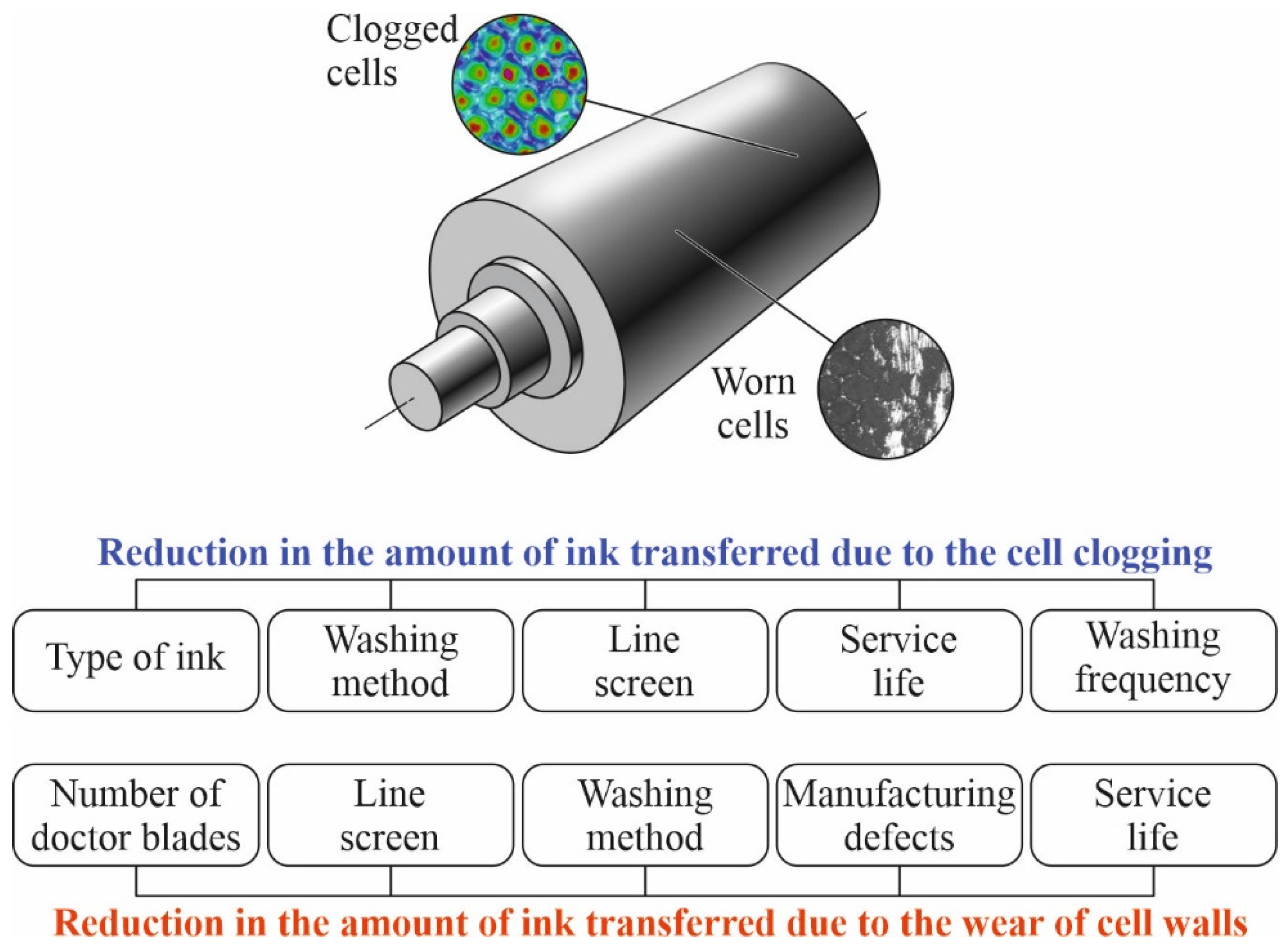
3.3. Wear of Anilox Rollers
3.3.1. Wear Dependence on Cell Size
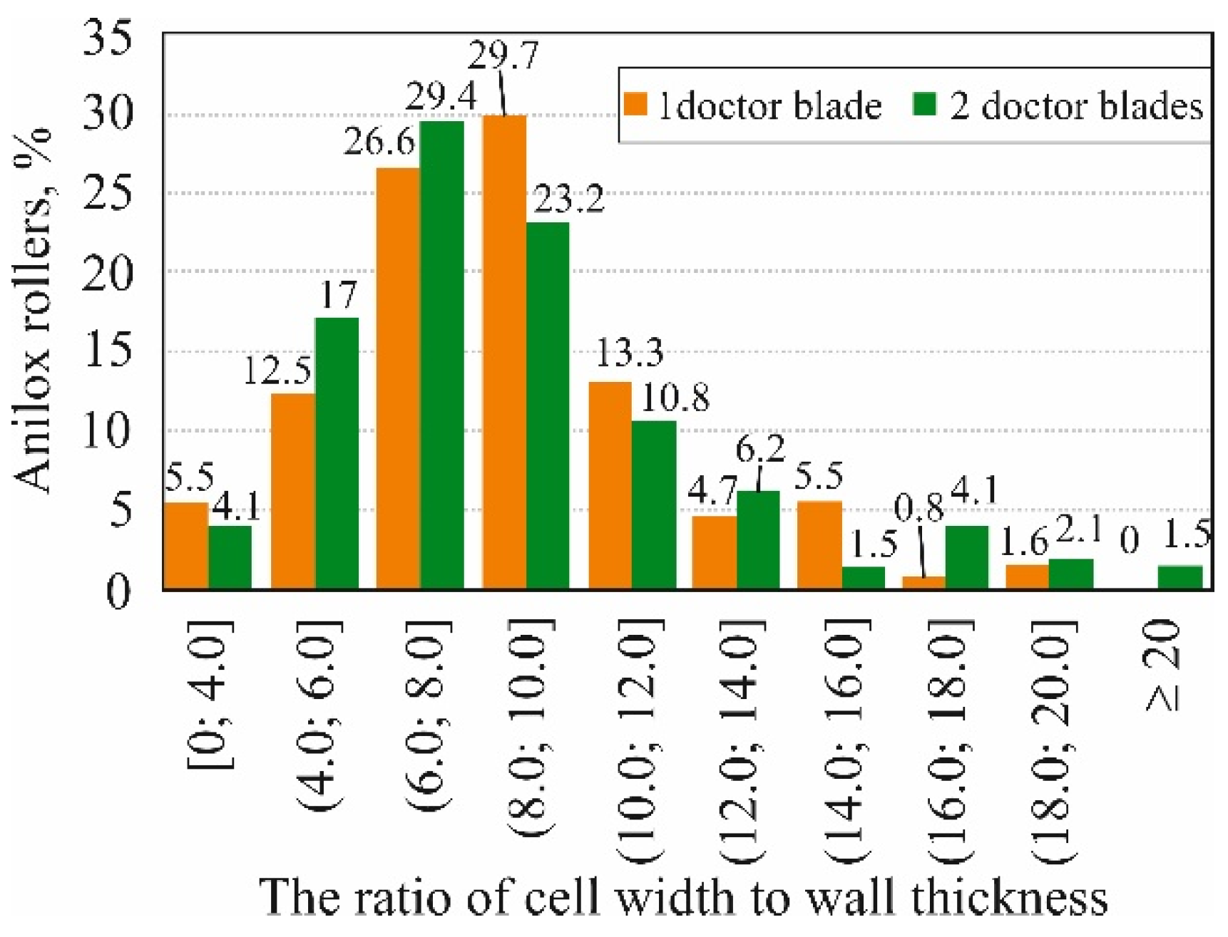
3.3.2. Dependence of Anilox Wear on Doctor Blade Number
3.3.3. Uniformity of Ink Transfer in a Worn Roller
4. Conclusions
- According to this study, no precise or only very limited methods of measuring the condition of anilox roller surfaces are used in Baltic printing houses. Printing machine operators are guided by their experience, and by comparing the appearance of prints.
- Anilox roller ink transfer changes over a wide range. A total of 26.6% of analysed anilox roller ink-transfer changes are within ±5% (recommended by anilox roller manufacturers). Some 13.2% of the anilox roller ink-transfer change was less than −35%, and 2.5% of the roller ink-transfer change was more than +25%. Large discrepancies in ink transfer from the ratings indicate potential difficulties for the print house in selecting the right anilox roller for each print job.
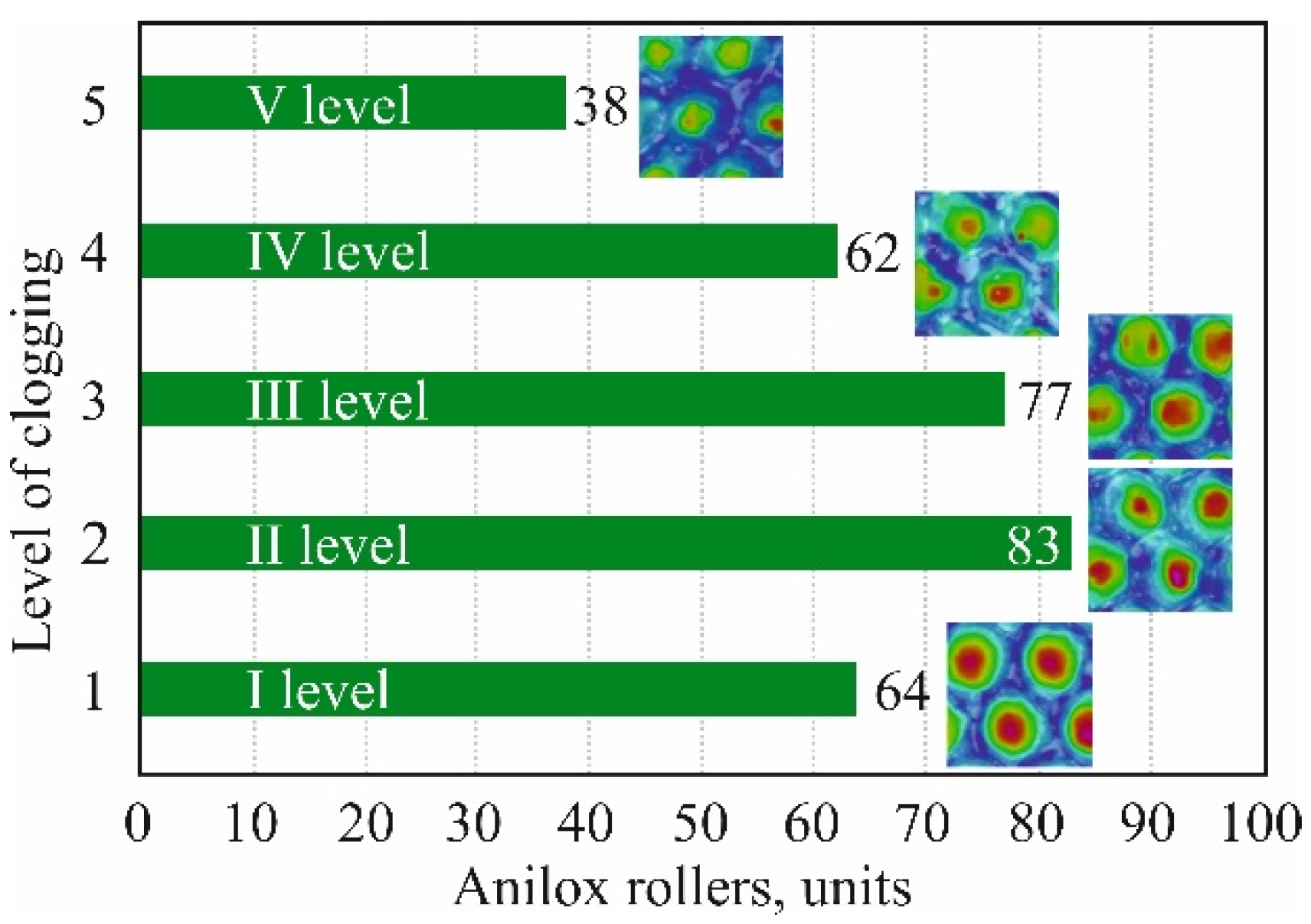
- A total of 177 of 324 anilox rollers had a clogging level of three or higher. This means that more than half of the anilox rollers in printing houses are not properly washed.
- Results showed that larger line screen anilox rollers tend to become more clogged. The average line screen in the first level pollution segment is 169 L/cm, and increases with an increasing pollution level until it reaches an average line screen of 428 L/cm in the fifth level pollution segment.
- Chambered two doctor blade systems have a greater effect on the wear of anilox rollers.
- Due to the observed high transfer unevenness in a worn anilox roller, it is recommended to take measurements at more than three locations when measuring the condition of such rollers.
- The influence of ink type (solvent-based, water-based, and UV/UV LED inks/EB inks) as well as different viscosities and other physical and chemical properties on the clogging of the cells of the anilox when assessing the anilox cell geometry;
- The efficiency of anilox roller cleaning methods, depending on the type of ink used and the geometry and line screen of the anilox cells;
- The influence of doctor blade conditions such as pressure applied to the blade, contact angle of doctor blade, and wear of the blades to the wear of the anilox roller;
- More detailed studies on the wear of the surface of anilox rollers are needed in order to clarify the methodology and recommendations for printing houses on the wear of anilox rollers.
Author Contributions
Funding
Institutional Review Board Statement
Informed Consent Statement
Data Availability Statement
Conflicts of Interest
References
- Flexographic Technical Association. Flexography: Principles and Practices, 6th ed.; Foundation of Flexographic Technical Association: New York, NY, USA, 2013; p. 610. [Google Scholar]
- Kippan, H. Handbook of Print Media; Springer: Berlin/Heidelberg, Germany, 2001. [Google Scholar]
- Packaging Impressions. Benchmarking and Worldwide Market Trends for Flexographic Printing. 2010. Available online: https://www.packagingimpressions.com/article/benchmarking-worldwide-market-trends-flexographic-printing-25008604 (accessed on 25 June 2021).
- Zhong, Z.W.; Ee, J.H.; Chen, S.H.; Shan, X.C. Parametric investigation of flexographic printing processes for R2R printed electronics. Mater. Manufact. Proc. 2020, 35, 564–571. [Google Scholar] [CrossRef]
- Cosnahan, T.; Watt, A.A.; Assender, H.E. Flexography printing for organic thin film transistors. Mater. Today Proc. 2018, 5, 16051–16057. [Google Scholar] [CrossRef]
- Huebler, A.C.; Doetz, F.; Kempa, H.; Katz, H.E.; Bartzsch, M.; Brandt, N.; Hennig, I.; Fuegmann, U.; Vaidyanathan, S.; Granstrom, J.; et al. Ring oscillator fabricated completely by means of mass-printing technologies. Org. Electron. 2007, 8, 480–486. [Google Scholar] [CrossRef]
- Alem, S.; Graddage, N.; Lu, J.; Kololuoma, T.; Movileanu, R.; Tao, Y. Flexographic printing of polycarbazole-based inverted solar cells. Org. Electron. 2018, 52, 146–152. [Google Scholar] [CrossRef]
- Deganello, D.; Cherry, J.A.; Gethin, D.T.; Claypole, T.C. Patterning of micro-scale conductive networks using reel-to-reel flexographic printing. Thin Solid Film. 2010, 518, 6113–6116. [Google Scholar] [CrossRef]
- Deganello, D.; Cherry, J.A.; Gethin, D.T.; Claypole, T.C. Impact of metered ink volume on reel-to-reel flexographic printed conductive networks for enhanced thin film conductivity. Thin Solid Film. 2012, 520, 2233–2237. [Google Scholar] [CrossRef]
- Johnson, J. Aspects of Flexographic Print Quality and Relationship to some Printing Parameters. Ph.D. Thesis, Karlstad University, Karlstad, Sweden, 2008. [Google Scholar]
- Johnson, J. The Influence of Moisture, Temperature, Pressure Pulse and Substrate on Print Quality in Flexographic Printing. Ph.D. Thesis, Karlstad University, Karlstad, Sweden, 2003. [Google Scholar]
- Valdec, D.; Zjakić, I.; Milković, M. The influence of variable parameters of flexographic printing on dot geometry of pre-printed printing substrate. Tech. Gaz. 2013, 20, 659–667. [Google Scholar]
- Folea, G.V.; Cazac, V. The Analysis of particularities and possibilities for ensuring quality in flexo printing. Ann. Acad. Rom. Sci. Ser. Eng. Sci. 2017, 9, 35–48. [Google Scholar]
- Havenko, S.; Ohirko, M.; Ryvak, P.; Kotmalova, O. Determining the factors that affect the quality of test prints at flexographic printing. East.-Eur. J. Enterp. Technol. 2020, 2, 104. [Google Scholar] [CrossRef]
- Gencoglu, E.F. E Influence of ink viscosity on dot gain and print density in flexography. Asian J. Chem. 2012, 5, 1999–2002. [Google Scholar]
- Gu, C.; Wang, Y.; Xing, J.; Dai, H. On the influence of viscosity of water-based inks and how the viscosity influences the dot gain in flexographic printing. J. Beijing Inst. Graph. Commun. 2008, 4, 4. [Google Scholar]
- Borbély, Á.; Szentgyörgyvölgyi, R. Colorimetric properties of flexographic printed foils: The effect of impression. Óbuda Univ. e-Bull. 2011, 2, 31–36. [Google Scholar]
- Lipiak, J. Methodology for assessing the factors affecting the quality and efficiency of flexographic printing process. Procedia Eng. 2017, 182, 403–411. [Google Scholar] [CrossRef]
- Bould, D.; Claypole, T.C.; Galton, D. Process parameters in flexography: Effect on UV ink transfer and image quality characteristics. J. Print Media Technol. Res. 2012, 1, 41–49. [Google Scholar]
- Morgan, M.L.; Holder, A.; Curtis, D.J.; Deganello, D. Formulation, characterisation and flexographic printing of novel Boger fluids to assess the effects of ink elasticity on print uniformity. Rheol. Acta 2018, 57, 105–112. [Google Scholar] [CrossRef] [Green Version]
- James, A. Anilox Technology Applications; FlexoTech: London, UK, 2013; pp. 36–37. [Google Scholar]
- Cherry, J.A. Ink Release Characteristics of Anilox Rolls. Ph.D. Thesis, Swansea University, Swansea, UK, 2007. [Google Scholar]
- Harper. Specifying the Right Anilox Roll; Harper Anilox & Coating Division: Charlotte, NC, USA, 2020; Available online: http://www.harperimage.com/AniloxRolls/Anilox-Guides/Specifying-the-Right-Anilox (accessed on 25 June 2020).
- Bould, D.C.; Hamblyn, S.M.; Gethin, D.T.; Claypole, T.C. Effect of impression pressure and anilox specification on solid and halftone density. Proc. Inst. Mech. Eng. Part B J. Eng. Manuf. 2011, 225, 699–709. [Google Scholar] [CrossRef]
- Blagodir, O.; Velychko, O. Study of anilox cell geometry impact on the ink volume transferred to the printing plate. Przegląd Pap. 2016, 72, 443–447. [Google Scholar]
- Poppen, M. The Secret to Print Consistency: Maintaining Anilox Roll Volume; FTA: New York, NY, USA, 2020; Available online: https://www.flexography.org/industry-news/print-consistency-maintain-anilox-roll-volume (accessed on 20 June 2020).
- Provident Group Ltd. Troika Group Ltd. Do You Really Know the Volume of Your Anilox Rolls? Provident LLC: Appleton, WI, USA, 2008; Available online: https://www.providentgrp.com/do-you-really-know-the-volume-of-your-anilox-rolls (accessed on 20 June 2020).
- Reilly, D.; Claypole, T.; Cox, K. Measuring Anilox Volume: FQC’s Gauge R&R Study; FTA: New York, NY, USA, 2010; Available online: https://www.flexography.org/industry-news/measuring-anilox-volume-fqc-gauge-rr-study (accessed on 20 June 2020).
- Khmiliarchuk, O.I.; Shubko, Y.S. Modeling of Anilox Cells Pollution Process; ELAKPI: Kiev, Ukraine, 2016; Available online: https://ela.kpi.ua/handle/123456789/16538 (accessed on 10 February 2021).
- Savickas, A.; Stonkus, R.; Jurkonis, E. Investigation of anilox roller cell clogging. J. Graph. Eng. Des. 2020, 11, 61–67. [Google Scholar] [CrossRef]


| Parameter | 1 Blade | 2 Blades |
|---|---|---|
| Number of measurements | 128 | 194 |
| Minimum value | 2.5 | 1.8 |
| Maximum value | 19.8 | 24.5 |
| Average | 8.8 | 8.8 |
| Median | 8.9 | 8.0 |
| Mode | 9.2 | 6.7 |
Publisher’s Note: MDPI stays neutral with regard to jurisdictional claims in published maps and institutional affiliations. |
© 2021 by the authors. Licensee MDPI, Basel, Switzerland. This article is an open access article distributed under the terms and conditions of the Creative Commons Attribution (CC BY) license (https://creativecommons.org/licenses/by/4.0/).
Share and Cite
Savickas, A.; Stonkus, R.; Jurkonis, E.; Iljin, I. Assessment of the Condition of Anilox Rollers. Coatings 2021, 11, 1301. https://doi.org/10.3390/coatings11111301
Savickas A, Stonkus R, Jurkonis E, Iljin I. Assessment of the Condition of Anilox Rollers. Coatings. 2021; 11(11):1301. https://doi.org/10.3390/coatings11111301
Chicago/Turabian StyleSavickas, Arnas, Rimantas Stonkus, Eugenijus Jurkonis, and Igor Iljin. 2021. "Assessment of the Condition of Anilox Rollers" Coatings 11, no. 11: 1301. https://doi.org/10.3390/coatings11111301
APA StyleSavickas, A., Stonkus, R., Jurkonis, E., & Iljin, I. (2021). Assessment of the Condition of Anilox Rollers. Coatings, 11(11), 1301. https://doi.org/10.3390/coatings11111301