1. Introduction
Over recent years, the market for a photovoltaic system has expanded rapidly. In addition to common types of rooftops, ground-mounted and building-integrated systems, countries around the world, such as Japan, USA, Italy, Spain, France, South Korea, Singapore, Australia, Brazil, India, China, Egypt, Poland, South Asia and Central Asia, are actively developing the floating photovoltaic (FPV) system, which is mainly installed on the surface of idle waters [
1,
2,
3,
4]. The FPV system is highly suitable for countries which are densely populated and highly dependent on imported energy, and it is expected to solve the developmental dilemma of insufficient land resources [
5,
6,
7,
8,
9]. Single-pile fixed systems or dual-pile fixed systems are suitable for shallow water or small water level changes, while floating systems with or without support are suitable for deep water or large water level changes, as depicted in
Figure 1. Supporting devices are commonly made from hot-dipped galvanized steel or aluminum. Concrete piles are generally used in fixed systems and piled into ground underwater directly. The components of the float in a floating system are almost always engineering plastics, most of which are high-density polyethylene (HDPE) [
10,
11].
In addition to the temperature of water (or environmental air) [
13], the durability of the plastic float is also affected by environmental air pollutants (e.g., ozone [
14]) and ultraviolet (UV) radiation [
15]. After the long-term synergistic effect of these factors, the surfaces of floats are likely oxidized or chalked, as shown in
Figure 2a. Moreover, sustaining faster wind speeds, higher wind pressures and larger vibrations on the water makes the floats more susceptible to cracking or fracturing, as shown in
Figure 2b. Rather than a direct emission from pollutant sources, ozone, a common environmental air pollutant, is a combination product of an oxygen molecule and an oxygen atom that is generated by a series of photochemical reactions of volatile organic compounds (VOCs), nitrogen oxides and carbon monoxides. Consequently, a higher ozone concentration can be observed on a sunny day. For example, the ozone concentration is easily above 100 ppb on a summer day and a higher concentration will be found on the surface of water due to stronger UV radiation. The reason why ozone can oxidize plastic rubber material has been mainly attributed to the high reactivity of ozone with the double-bond structure of plastic rubber material, which would be rapidly broken into small carboxylic acids and aldehydes. For this reason, ozone can be applied to the accelerated-aging test of plastic rubber material [
16,
17].
However, due to environmental conditions on the surface of water being harsher than on the ground, regulations or standards that are relevant to the application of a float in an FPV system are insufficient in the current situation [
18]. Currently, Taiwan has plans to install FPV systems on water surfaces in areas such as reservoirs, lakes, ponds and fish farms, and there is a lack of data to show whether the floats are safe enough to use sustainably [
19]. As a result, this study aims to investigate the durability of floats through accelerated aging tests as a reference for the future evaluation of the minimum requirements of floats.
2. Materials and Methods
We utilized an accelerated aging technique in this study to simulate the long-term influence of ozone or UV radiation on the float upon the surface of the water. The float-durability-test-system was employed to control the accelerated-aging parameters, which was inclusive of temperature, relative humidity, and ozone concentration or UV light intensity. For the purpose of evaluating the durability of the float in an FPV system faster and more effectively, the ozone-aging test was conducted under the harshest conditions, (80 ± 1) °C/(90 ± 1)% RH/(500 ± 1) ppm, for 7 days (168 h) as the experimental group; alternatively, the 7-day damp heat test, (80 ± 1) °C/(90 ± 1)% RH/(0 ± 1) ppm, was designed as the control group to distinguish the influence of a high ozone concentration, and the blank control group was designed in the environment of normal temperature, humidity and without ozone in order to distinguish the influence of high temperature and humidity. Regarding the UV aging test, taking IEC 61215-2 [
20] and IEC 61730-2 [
21] as a reference, the single-sided UV aging test was performed under the conditions of (60 ± 5) °C/(0–1)% RH/(100–150) W∙m
−2 (2–3 times sunlight intensity) for (400–600) h (around 17–25 days) to reach the amount of UV exposure 60 kW∙h∙m
−2. IEC 61215-2 describes the test procedures for the design qualification and type approval of terrestrial photovoltaic modules that are suitable for long-term operation in general open-air climates. The scope of IEC 61730-2 is to provide the testing sequence and pass criteria intended to verify the safety of PV modules. In addition, due to directional UV light, the double-sided UV aging test was designed and performed under the same conditions as the single-sided test for 800 to 1200 h (around 34–50 days).
Two brands of HDPE extrusion specimens, identical to the material of the float, including USI (denoted by A) and Formosa Plastics (denoted by B) in Taiwan, were selected as the subjects for the study with two different thicknesses (3 and 6 mm). Generally speaking, the floats were mostly made out of 3 mm HDPE as a standard thickness. Only a minority of floats that were reinforced for special purposes were made from 5–6 mm HDPE. The subjects were divided into four groups in terms of source and thickness and denoted by A3, A6, B3 and B6. Each sample group was directly cut into the type I specimen of ASTM D638 [
22] from the same extruded sheet.
Among the four groups of HDPE specimens, non-aged specimens are denoted by T0; specimens that underwent the ozone-aging test (80 °C/95% RH/500 ppm/7 days) were denoted by T1; specimens that underwent the double-sided UV-aging test (60 °C/0% RH/60 kW∙h∙m−2/34 days) were denoted by T2; specimens that underwent the single-sided UV-aging test (60 °C/0% RH/60 kW∙h∙m−2/17 days) were denoted by T3; specimens that underwent the damp heat test (80 °C/95% RH/0 ppm/7 days) were denoted by T4. Each condition had an equal number of specimens (n = 5), denoted from 01 to 05. Thus, 100 specimens (4 × 5 × 5) were tested in total. The subject that was denoted A3-T0-01 represented the first 3 mm thickness of the brand A-HDPE specimen without any aging test. Similarly, the subject denoted B6-T1-05 represented the fifth 6 mm thickness of the brand B-HDPE specimen with the T1-aging test.
The test system (CMS, UA-2074) and test flow chart of the damp heat-aging and ozone-aging tests are shown in
Figure 3a. The test system (Center for Measurement Standards, Hsinchu, Taiwan) and test flow chart of the single-sided and double-sided UV-aging tests are also schemed in
Figure 3b. Visual observations, the Fourier-transform infrared (FTIR) spectrum analysis, and the tensile test were conducted to investigate the chemical and mechanical properties of HDPE specimens following the aging tests.
3. Results and Discussion
3.1. Visual Observation
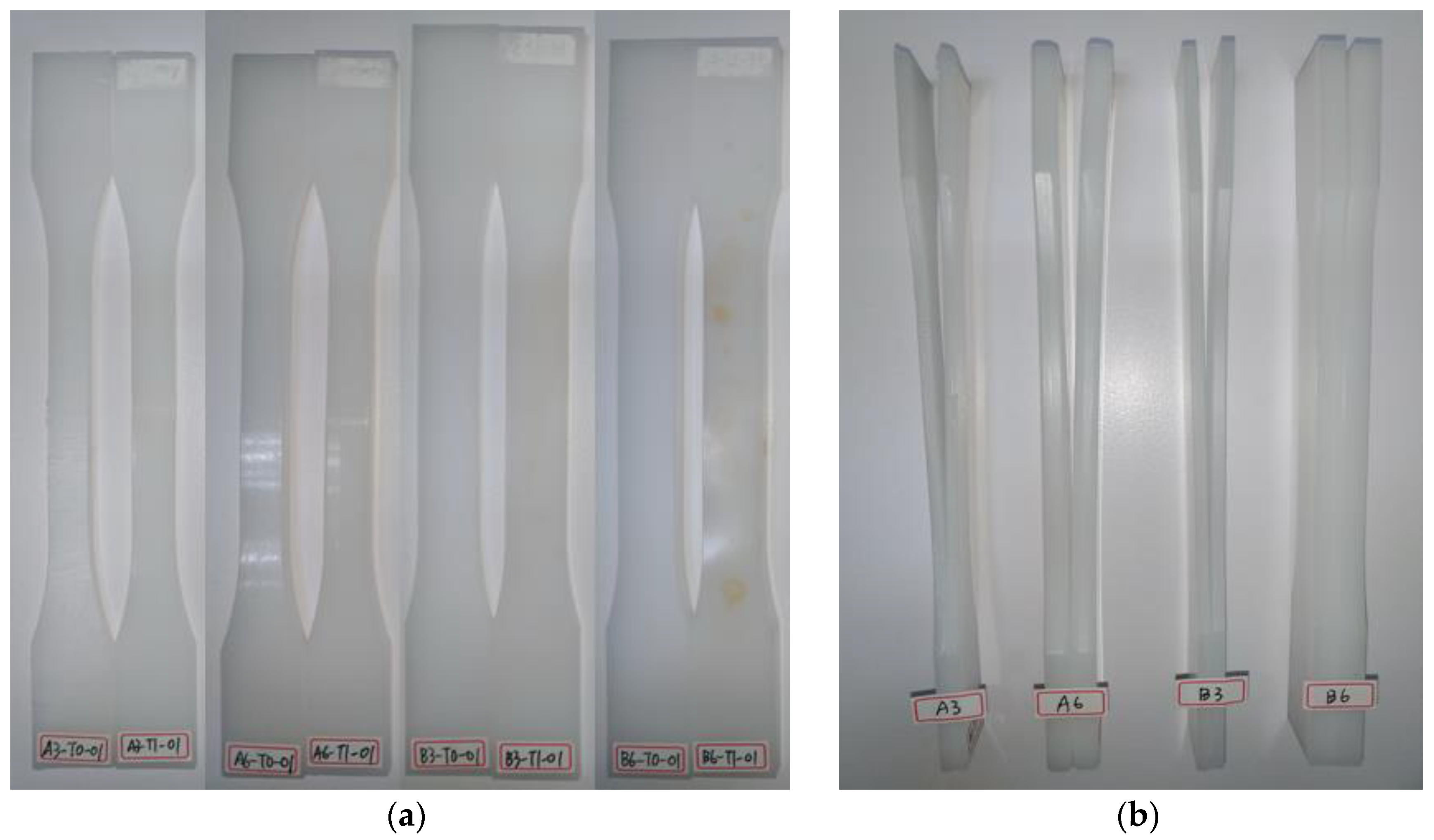
Figure 4a displays the visual observations of the specimens from the front side, before and after the ozone-aging test among the four groups of HDPE specimens. Compared with the non-aged specimens, the surfaces of the specimens after ozone aging were not found to contain any obvious deterioration or cracks, even though parts of the surfaces of the specimens had turned slightly yellow. A possible explanation is that the ozone only damages the molecular structure of the surfaces of the plastic and rubber under the zero-strain ozone aging test, rather than causing surface deterioration or cracks under the static- or dynamic-strain ozone aging tests. However, observations of the side face revealed that four groups of specimens after ozone aging showed different degrees of warping. Except for the thicker B6 specimens, which showed no apparent degree of warping, the other three groups of specimens (A3, A6, B3) demonstrated a high degree of warping, as observed in
Figure 4b. HDPE specimens after damp heat aging, single-sided UV aging, and double-sided UV aging were not found to have any distinct deterioration or cracks, with neither the naked eye nor with a 10-fold optical microscope.
3.2. Chemical Property Test
The chemical properties of HDPE specimens were studied by FTIR spectrum analysis in order to investigate whether the functional groups changed during the aging tests. The FTIR spectra were obtained by an attenuated total reflectance Fourier-transform infrared (ATR-FTIR) spectrometer (PERKINELMER, Waltham, MA, USA).
Figure 5a–d illustrate the FTIR spectra of the four groups of HDPE specimens under different aging conditions. All FTIR spectra of the four groups showed obvious differences at 1711 cm
−1, which indicated that a significant number carboxyl groups (-COOH) were produced on the surfaces of the specimens after the aging tests. This could be attributed to ozone, which oxidizes long-chain hydrocarbons to form oxygen-containing functional groups, the majority of which are carboxyl groups and the minority of which are ketone groups (-COR) and ester groups (-COOR), which can be identified at 1730 and 1767 cm
−1, respectively. By contrast, there were two strong peaks (2847 and 2914 cm
−1, the stretching of methylene group (-CH2-)) and two medium-strong peaks (1461 and 1471 cm
−1, the bending of methylene group) of the aged specimens that showed no difference from the non-aged specimens. One set of peaks can be used as the base peak (2847 and 2914 cm
−1 were chosen in this study) to calculate the relative carboxyl-group content (A
COOH/A
CH2), as an index to evaluate the aging degree of the HDPE specimens. The similar wavenumbers of the oxygen-containing groups after ozonation of the HDPE specimens were indicated, and the relative content of the carboxyl group (-COOH) was far greater than other oxygen-containing groups [
23].
After the peak-area analysis of the FTIR spectra, the value of A
COOH/A
CH2 for the HDPE specimens can be calculated, as listed in
Table 1. The descending order of A
COOH/A
CH2 values (T1 > T2 > T3 > T4~T0) of the four groups of HDPE specimens indicated that damp heat aging had a limited effect on producing oxygen-containing functional groups. Therefore, the transformation of the chemical properties of HDPE specimens could mostly be ascribed to the concentrated ozone environment or the UV irradiation rather than the damp heat environment. The significant change of functional groups happened in both the ozone and UV aging tests, and more oxygen-containing functional groups had been produced by ozone aging (7 days) than both single-sided (17 days) and double-sided (34 days) UV aging. In other words, the extent of ozone aging was more severe even though the duration of the ozone-aging test was shorter. The difference between single-sided UV aging and double-sided UV aging, theoretically speaking, is that the front side of the HDPE specimen would not have been irradiated when UV light was irradiating from the back side. However, the experimental results seem to suggest that oxygen-containing functional groups were being produced continuously on the front side of the HDPE specimens. These results suggest that free radicals generated by UV irradiation lead to the chain reaction of oxidation continuously destroying the molecular bonding of HDPE. Even though the amount of UV exposure to the front or back side was identical (60 kW∙h∙m
−2), the front side of HDPE specimens after double-sided (34 days) UV aging was more aged than after single-sided (17 days) UV aging, owing to a longer oxidation duration. Moreover, the ozone-aging of brand B specimens was more evident than brand A specimens, while the UV aging of brand B specimens was less evident. The likely reason may be the fact that a UV absorber or light-stabilizer had been added to the HDPE raw material pellets of brand B, which added a degree of anti-UV ability. It is worth noting that the yellowing area caused by UV aging was only found on the surfaces of specimens when they were cut into thin slices for ATR-FTIR analysis. Thus, FTIR spectra were mainly based on the yellowing area.
3.3. Mechanical Property Test
A universal testing machine (MTS, C43.504, Eden Prairie, MN, USA) was utilized to study the mechanical properties of HDPE specimens and to investigate whether the tensile strength was changed during the aging tests.
During the tensile test, some HDPE specimens fractured while others did not.
Figure 6 illustrates a typical load–elongation curve. When tensile strain increased, tensile stress rose to the yield point (elastic deformation) and then decreased gradually (plastic deformation). In the end, tensile stress either held or gradually increased until the break point or end point.
Table 2 provides the tensile test data of the four groups of HDPE specimens under different aging conditions. The results of the ozone-aging test showed that there was no clear difference between the tensile stress at the yield point between T0 (blank control group), T4 (control group), and T1 (experimental group) in the four groups of HDPE specimens, but the percentage of elongation of aged samples at the yield point was promoted slightly. Additionally, except for the B3 group, both the non-aged and aged samples in the A6 and B6 groups were all broken during the tensile test, and the tensile stress at the break point declined slightly; that is, it became soft. Furthermore, in comparison with non-aged specimens (A3-T0), the fracture number of ozone-aged specimens (A3-T1) increased from 0 to 5, whereas that of the damp heat-aged samples (A3-T4) remained zero. These data reveal that the increase in the fracture number of the HDPE specimen could result from the concentrated ozone instead of the damp heat environment. A preliminary speculation is that the surface of the HDPE specimen being oxidized by ozone may result in the increase in the percentage of elongation at the yield point, the decrease in tensile stress at the break point, and the specimen becoming easier to break.
The results of the UV aging test demonstrated that the tensile stress and percentage of elongation at the yield point fell dramatically in comparison to T0 (blank control group), T3 (single-sided group), and T2 (double-sided group), in the four groups of HDPE specimens. In addition, both non-aged and aged samples in the A6 and B6 groups were all broken in the tensile test. Both groups showed that the tensile stress at the break point increased dramatically; that is, it became hard, and the percentage of elongation at the break point dropped significantly. In other words, it became brittle. Likewise, in comparison with non-aged specimens (A3-T0), the fracture number of UV-aged specimens (A3-T2 and A3-T3) increased from 0 to 5, and identical results were found in the B3 group, too. These data suggest that UV aging made the HDPE specimens harder and more brittle than ozone aging. The changes to the mechanical properties (including tensile strength, elongation at the break point, maximum load-bearing capacity, impact resistance and hardness) of HDPE sheets after 1152 h of accelerated UV exposure were evaluated, and the results also showed that the HDPE sheet became harder and more brittle after UV aging [
24]. One possible reason for this could be that ozone oxidization usually occurs at the surface of the HDPE specimen, whereas UV irradiation could damage the deeper layer of the HDPE specimen. As for the single- and double-sided UV aging of HDPE specimens, there was nothing noticeably different between them.
4. Conclusions
Based on the results of FTIR spectrum analysis and the tensile test of four groups of HDPE extrusion specimens, we may conclude that the 7-day damp heat test neither produced more oxygen-containing functional groups by FTIR spectrum analysis nor became easier to break by the tensile test. Furthermore, the relative carboxyl group content (ACOOH/ACH2) of the 7-day ozone-aging test was 3–7 times higher than that of the 17-day UV-aging test, which suggests that more oxygen-containing functional groups were produced after the ozone-aging test than the UV-aging test. However, a higher tensile stress and a lower percentage of elongation at the break point occurred after the 17-day UV-aging test than after the 7-day ozone aging test, which suggests that UV aging would make HDPE specimens harder and more brittle than ozone aging. In conclusion, both ozone- and UVaging tests can evaluate the durability of a float quickly and efficiently, and both accelerated-aging tests are worth further investigation.
However, due to the environmental conditions on the surface of water being harsher than on the ground, regulations or standards relevant to the application of floats in FPV systems are insufficient in the current situation. Users can only rely on the test data provided by manufacturers or other entities to evaluate the lifetime of the float, or they can unilaterally believe the uncertified service life of a float that manufacturers or other entities provide. Currently, Taiwan has plans to install FPV systems on water surfaces in areas such as reservoirs, lakes, ponds and fish farms, and there is a lack of data to show whether floats are safe enough to use sustainably. As a consequence, both the safety and durability of floats in FPV systems are urgent issues needing to be resolved when the government is positively implementing green energy and widely installing FPV systems. Standard test methods of floats in FPV systems must be established as soon as possible and then used to evaluate the minimum requirements of a float to further enhance the minimum service life, to reduce the risk of damage to floats and to eventually reduce the maintenance costs.
Author Contributions
Conceptualization, C.-K.L.; methodology, C.-K.L.; validation, C.-K.L.; formal analysis, Z.-R.K.; data curation, C.-K.L.; writing—original draft preparation, C.-K.L. and Z.-R.K.; writing—review and editing, M.-J.K.; visualization, C.-K.L.; supervision, M.-J.K.; pro-ject administration, T.-C.W.; funding acquisition, T.-C.W. All authors have read and agreed to the published version of the manuscript.
Funding
This research was funded by the Bureau of Energy, Ministry of Economic Affairs, Grant No. 107-D0307.
Institutional Review Board Statement
Not applicable.
Informed Consent Statement
Not applicable.
Data Availability Statement
The data presented in this study are available on request from the corresponding author. The data are not publicly available because this research was funded by the project of government.
Acknowledgments
The authors would like to acknowledge the financial support of the National Natural Science Foundation of China and the Natural Science Foundation of Hunan Province, China. The grant numbers are 52075552 and 2019JJ70081, respectively.
Conflicts of Interest
The authors declare no conflict of interest.
References
- Trapani, K.; Redón Santafé, M. A Review of Floating Photovoltaic Installations: 2007–2013. Prog. Photovolt Res. Appl. 2015, 23, 524–532. [Google Scholar] [CrossRef] [Green Version]
- Abid, M.; Abid, Z.; Sagin, J.; Murtaza, R.; Sarbassov, D.; Shabbir, M. Prospects of Floating Photovoltaic Technology and Its Implementation in Central and South Asian Countries. Int. J. Environ. Sci. Technol. 2019, 16, 1755–1762. [Google Scholar] [CrossRef]
- Ravichandran, N.; Fayek, H.H.; Rusu, E. Emerging Floating Photovoltaic System—Case Studies High Dam and Aswan Reservoir in Egypt. Processes 2021, 9, 1005. [Google Scholar] [CrossRef]
- Kolerski, T.; Radan, P.; Gąsiorowski, D. Ice Load Characteristics on Floating Photovoltaic Platform. Energies 2021, 14, 2466. [Google Scholar] [CrossRef]
- Kim, S.-H.; Yoon, S.-J.; Choi, W.; Choi, K.-B. Application of Floating Photovoltaic Energy Generation Systems in South Korea. Sustainability 2016, 8, 1333. [Google Scholar] [CrossRef] [Green Version]
- Kim, S.-H.; Yoon, S.-J.; Choi, W. Design and Construction of 1 MW Class Floating PV Generation Structural System Using FRP Members. Energies 2017, 10, 1142. [Google Scholar] [CrossRef] [Green Version]
- Kim, S.-M.; Oh, M.; Park, H.-D. Analysis and Prioritization of the Floating Photovoltaic System Potential for Reservoirs in Korea. Appl. Sci. 2019, 9, 395. [Google Scholar] [CrossRef] [Green Version]
- Kim, S.-H.; Baek, S.-C.; Choi, K.-B.; Park, S.-J. Design and Installation of 500-kW Floating Photovoltaic Structures Using High-Durability Steel. Energies 2020, 13, 4996. [Google Scholar] [CrossRef]
- Lee, J.-H.; You, Y.-J.; Saeed, M.A.; Kim, S.-H.; Choi, S.-H.; Kim, S.-M.; Lee, S.-Y.; Park, J.-S.; Shim, J.-W. Undoped Tin Dioxide Transparent Electrodes for Efficient and Cost-Effective Indoor Organic Photovoltaics (SnO2 Electrode for Indoor Organic Photovoltaics). NPG Asia Mater. 2021, 13, 43. [Google Scholar] [CrossRef]
- Sahu, A.; Yadav, N.; Sudhakar, K. Floating Photovoltaic Power Plant: A Review. Renew. Sust. Energ. Rev. 2016, 66, 815–824. [Google Scholar] [CrossRef]
- Riahinezhad, M.; Hallman, M.; Masson, J.-F. Critical Review of Polymeric Building Envelope Materials: Degradation, Durability and Service Life Prediction. Buildings 2021, 11, 299. [Google Scholar] [CrossRef]
- Liu, C.-K.; Kong, Z.-R.; Kao, M.-J.; Wu, T.-C. A Novel Accelerated Corrosion Test for Supporting Devices in a Floating Photovoltaic System. Appl. Sci. 2021, 11, 3308. [Google Scholar] [CrossRef]
- International Organization for Standardization. Plastics Piping and Ducting Systems—Determination of the Long-Term Hydrostatic Strength of Thermoplastics Materials in Pipe Form by Extrapolation; ISO 9080; International Organization for Standardization: Geneva, Switzerland, 2012. [Google Scholar]
- Park, J.-H.; Singh, J.K.; Lee, H.-S. Ozone Resistance, Water Permeability, and Concrete Adhesion of Metallic Films Sprayed on a Concrete Structure for Advanced Water Purification. Coatings 2017, 7, 41. [Google Scholar] [CrossRef] [Green Version]
- Rossi, S.; Lindmark, H.; Fedel, M. Colored Paints Containing NIR-Reflective Pigments Exposed to Accelerated Ultraviolet Radiation Aging with Possible Application as Roof Coatings. Coatings 2020, 10, 1135. [Google Scholar] [CrossRef]
- International Organization for Standardization. Rubber and Plastics Hoses—Assessment of Ozone Resistance Under Static Conditions; ISO 7326; International Organization for Standardization: Geneva, Switzerland, 2006. [Google Scholar]
- European Committee for Electrotechnical Standardization. Flexible Sheets for Waterproofing—Determination of Resistance to Ozone—Plastic and Rubber Sheets for Roof Waterproofing; EN 1844; European Committee for Electrotechnical Standardization: Brussels, Belgium, 2013. [Google Scholar]
- Liu, H.; Krishna, V.; Leung, J.L.; Reindl, T.; Zhao, L. Field Experience and Performance Analysis of Floating PV Technologies in the Tropics. Prog. Photovolt: Res. Appl. 2018, 26, 957–967. [Google Scholar] [CrossRef]
- Sudhakar, K. SWOT Analysis of Floating Solar Plants. MOJ Sol. Photoen. Sys. 2019, 3, 20–22. [Google Scholar]
- International Electrotechnical Commission. Terrestrial Photovoltaic (PV) Modules—Design Qualification and Type Approval—Part 2: Test Procedures; IEC 61215-2; International Electrotechnical Commission: Geneva, Switzerland, 2016. [Google Scholar]
- International Electrotechnical Commission. Photovoltaic (PV) Module Safety Qualification—Part 2: Requirements for Testing; IEC 61730-2; International Electrotechnical Commission: Geneva, Switzerland, 2016. [Google Scholar]
- American Society for Testing and Materials. Standard Test Method for Tensile Properties of Plastics; ASTM D638; American Society for Testing and Materials: West Conshohocken, PA, USA, 2014. [Google Scholar]
- Zhou, M.; Fu, Y.; Xu, W. Oxidation Reaction of HDPE with Ozone. Polym. Mater. Sci. Eng. 2004, 20, 101–103. [Google Scholar]
- Sahu, A.K.; Sudhakar, K. Effect of UV Exposure on Bimodal HDPE Floats for Floating Solar Application. J. Mater. Res. Technol. 2019, 8, 147–156. [Google Scholar] [CrossRef]
| Publisher’s Note: MDPI stays neutral with regard to jurisdictional claims in published maps and institutional affiliations. |
© 2021 by the authors. Licensee MDPI, Basel, Switzerland. This article is an open access article distributed under the terms and conditions of the Creative Commons Attribution (CC BY) license (https://creativecommons.org/licenses/by/4.0/).


