Article

Defective Microwave Photonic Crystals for Salinity Detection

1
College of Food Science and Technology, Nanjing Agricultural University, Nanjing 210095, China
2
Department of Physics, Nanjing Agricultural University, Nanjing 210095, China
*
Author to whom correspondence should be addressed.
Coatings 2021, 11(10), 1243; https://doi.org/10.3390/coatings11101243
Submission received: 15 August 2021 / Revised: 21 September 2021 / Accepted: 8 October 2021 / Published: 13 October 2021

Abstract

:
In this paper, defective microwave photonic crystals (MPCs) are designed to sense the salinity of aqueous solutions. The defective MPC sensors are constructed by two kinds of microwave dielectric layers and one defective salt solution layer. Transfer matrix method (TMM) for lossy medium is developed to calculate the transmittance spectra of the sensors. It is found that the peak transmittance of both the defective resonance within the microwave band gap (MBG) and transmitting modes outside the MBG monotonously decrease with the increase of salinity, while the resonant and transmitting mode frequencies remain unchanged. By comparing the four MPC sensor structures, the first transmitting mode in the upper frequency band outside the MBG of the 15-layer MPC sensor has the largest salinity sensing range from 0 to 40‰ with relative stable detecting sensitivity. The sensing principle is based on the fact that the dielectric loss factor of saline solution is much more sensitive to salinity than the dielectric constant in the microwave frequency band. The sensitivity, quality factor, and salinity detection range of the MPC sensors are calculated and compared. The reported defective MPC sensors are suitable to be used for non-contact salinity detection.

1. Introduction

Salt plays an important role in human life as it has been broadly used in food preparation since prehistoric times [1]. As a result, it is regarded as the most important food flavoring additive. However, the intake of excessive salt from foods and beverages may lead to some serious health problems, such as hypertension, cardiovascular disease, stomach cancer, osteoporosis, kidney disease, and obesity [2,3]. The National Food Safety Standard for Uses of Food Additives (GB2760-2011) in China regulated the additive amount of sodium chloride in foods, beverages, and condiments [4]. Therefore, it is important to determine the salt contents in foods and beverages during both their manufacturing processes and shelf-life, so as to ensure the products’ quality. Moreover, salinity sensing is widely applied to agriculture [5], marine environment monitoring [6], and oilfield water injection engineering [7].
Traditional chemically-based methods, such as chromatographic techniques, are widely used for testing the salt content of aqueous solutions [8,9]. However, these methods usually take a long measurement and processing time to determine the content of salt in liquid solutions and require additional chemical reagents. Moreover, the spectroscopy is an expensive instrument that requires professional personnel training. Hence, some physically-based methods associated with testing the electrical conductivity, optical refractive index, and dielectric properties of saline solution have garnered extensive attention. Their basic advantages include online salinity sensing and no need of chemical materials for conducting complicated analytical procedures [10].
At present, there have been many physical techniques reported to measure the salinity of aqueous solutions, such as the electrical conductivity measurement [11,12,13], optical sensing [14,15,16,17,18], ultrasonic velocity measurement [19], and microwave sensing [20,21,22,23]. The measuring and sensing principles are based on the dependence of conductivity, refractive index, or microwave dielectric properties on the salinity of aqueous solutions. The conventional technique of detecting salinity based on solution electrical conductivity, which depends on the amount of chlorine ions in the water solution, is not only sensitive to ambient environment parameters, such as temperature and pressure, but also vulnerable to corrosion by saline water [24]. Hence, salinity sensors based on optical and microwave techniques have been receiving greater attention for their unique merits. In general, the working principles of microwave or optical sensors are based on measuring measurands as the signal intensity or optical refractive index to indirectly determine the salinity of aqueous solutions [24,25]. The optical refractive index is an inherent characteristic of salt solutions and optical sensors were usually designed to measure the optical refractive index for salinity detection. Typical optical sensing structures include optical fibers [26,27,28,29], photonic crystals [30,31,32,33], and some specific optical resonators [34]. However, most reported optical sensors are designed to sense the salinity or optical refractive index by measuring the wavelength shift of the resonance [26,27,28,31,32,33,34]. It indicates that optical sources and receivers working in wide frequency bands are needed to measure the optical spectra, which will increase the system cost. Recently, microwave sensors for salinity detection garner more attention due to its low-cost and easy fabrication [35,36,37,38]. The detecting principles are mostly based on the effects of salinity on the dielectric properties of salt solutions [39,40,41], which can be sensed by using microwave transmission, reflection, or resonance techniques. Typical microwave resonant sensing structures include the patch antennas [3,35], split ring resonators [36,37], and cavity resonators [38]. However, these microwave sensors make both the resonant intensity and frequency change with the variation of salinity, which will cause a complex data process in determining accurate salinity. In addition, the metallic part of the sensors is also vulnerable to corrosion when it gets in touch with the salt solution under testing.
In this paper, inspired by both the photonic crystal sensors that work in optical frequency regime [31] and specific microwave dielectric properties of saline solution [41], one-dimensional defective microwave photonic crystals (MPCs) are proposed to measure the salinity of aqueous solutions. The sensing principle is based on the fact that the dielectric constant is insensitive to salinity and the dielectric loss factor is much sensitive to the salinity of saline solution. Both defective resonance and transmitting modes of the defective MPC sensors can be used to detect the salinity, where the resonance and transmitting mode transmittance decreases with an increase of salinity, but the resonant and transmitting mode frequencies remain unchanged. The merits of the proposed defective MPC salinity sensors lie in the narrowband signal transmitting and detection, non-contact, and wide-range measurement of salinity.

2. Materials and Methods

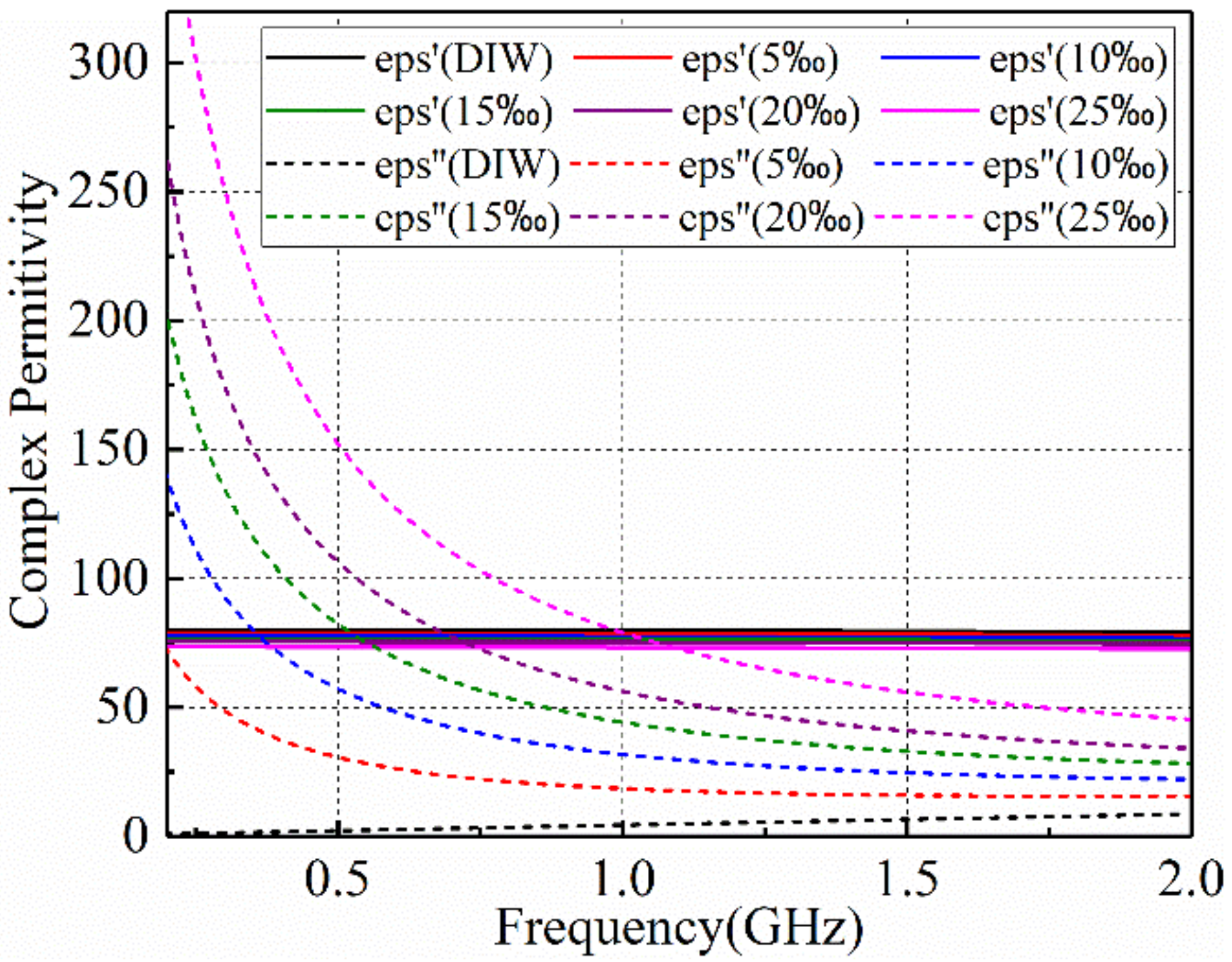
2.1. Microwave Dielectric Properites of Salt Solution

For the estimation of the salinity of aqueous solutions by using electromagnetic methods, the choice of a suitable frequency range is a very important parameter. The concentration of salt affects the microwave dielectric properties of aqueous solutions, which can be seen by comparing the complex permittivity of saline solution at different salt concentrations. NaCl is the principle salt in both foods and seawater and 2 famous dispersive models for determining the complex permittivity of saline solution are reported (Stogryn model [39] and Klein and Swift model [40]). Saline solution is considered as a non-magnetic dielectric material and its complex dielectric permittivity in microwave bands can be calculated by Debye expression [39,40]:
ε ^ ω , T , S = ε 0 ε + ε 0 ε s T , S ε 1 + j ω τ T , S j σ T , S ω
where ω = 2 π f is the radian frequency with f , ε is the dielectric constant at infinite frequency and it is usually taken to be a constant value of 4.9 in the microwave frequency regime, ε s T , S is the static dielectric constant, τ T , S is the relaxation time, σ T , S is the ionic conductivity and ε 0 = 8.854 × 10⁻¹² F/m is the permittivity of free space. It is found that the static dielectric constant, relaxation time, and ionic conductivity are functions of the seawater temperature T and salinity S . Their regression functions are fitted based on the experimental results conducted at the microwave frequencies [39,40]. A general form of the complex permittivity is given as ε ^ ( ω ) = ε ( ω ) j ε ( ω ) , and the real and image parts are given as:
ε ( ω ) = ε 0 ε + ε s ε 1 + ω τ 2
ε ( ω ) = ε 0 ω τ ε s ε 1 + ω τ 2 + σ ω
Making use of the regression equations for static dielectric constant, relaxation time, and ionic conductivity reported in Refs. [39,40], the complex permittivity at different salinity can be calculated. At a fixed temperature, it has been observed that the dielectric constant is insensitive to the salinity, but the dielectric loss increases rapidly with the increase of salinity [41].

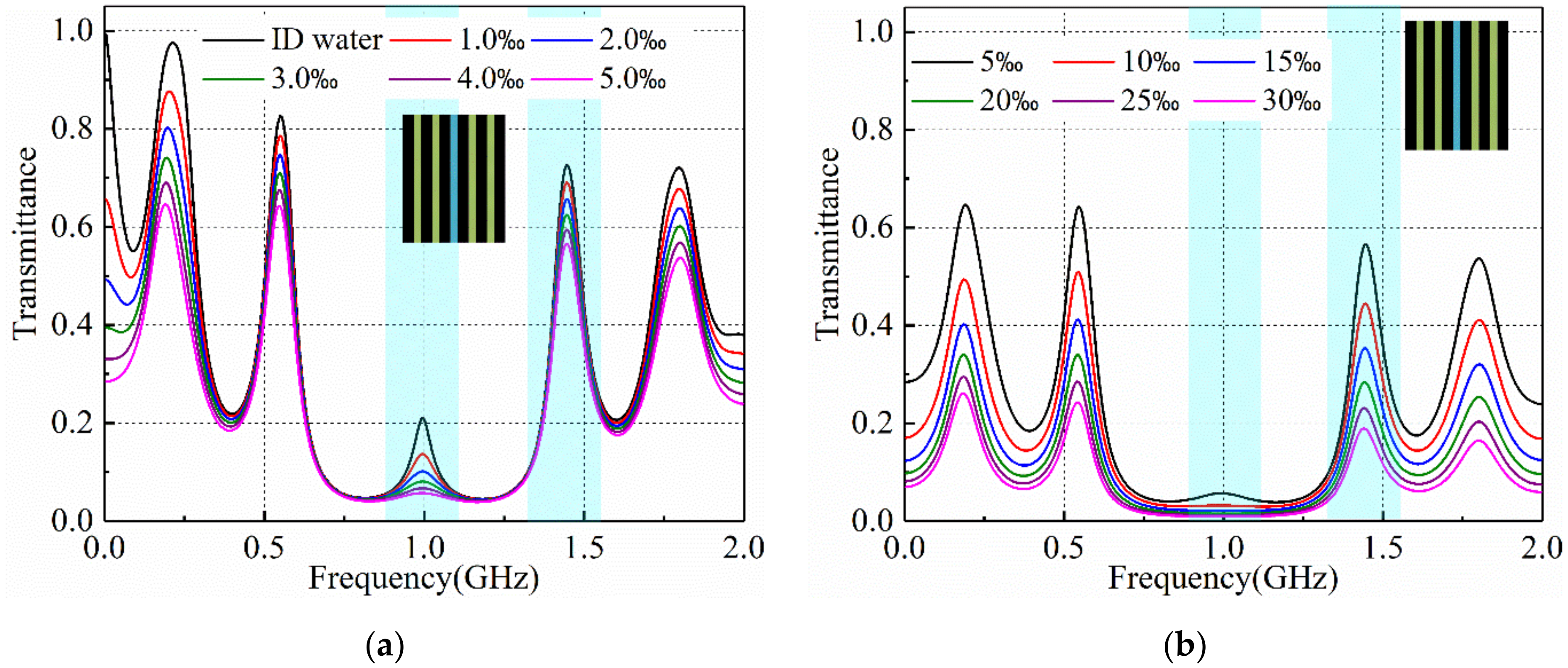
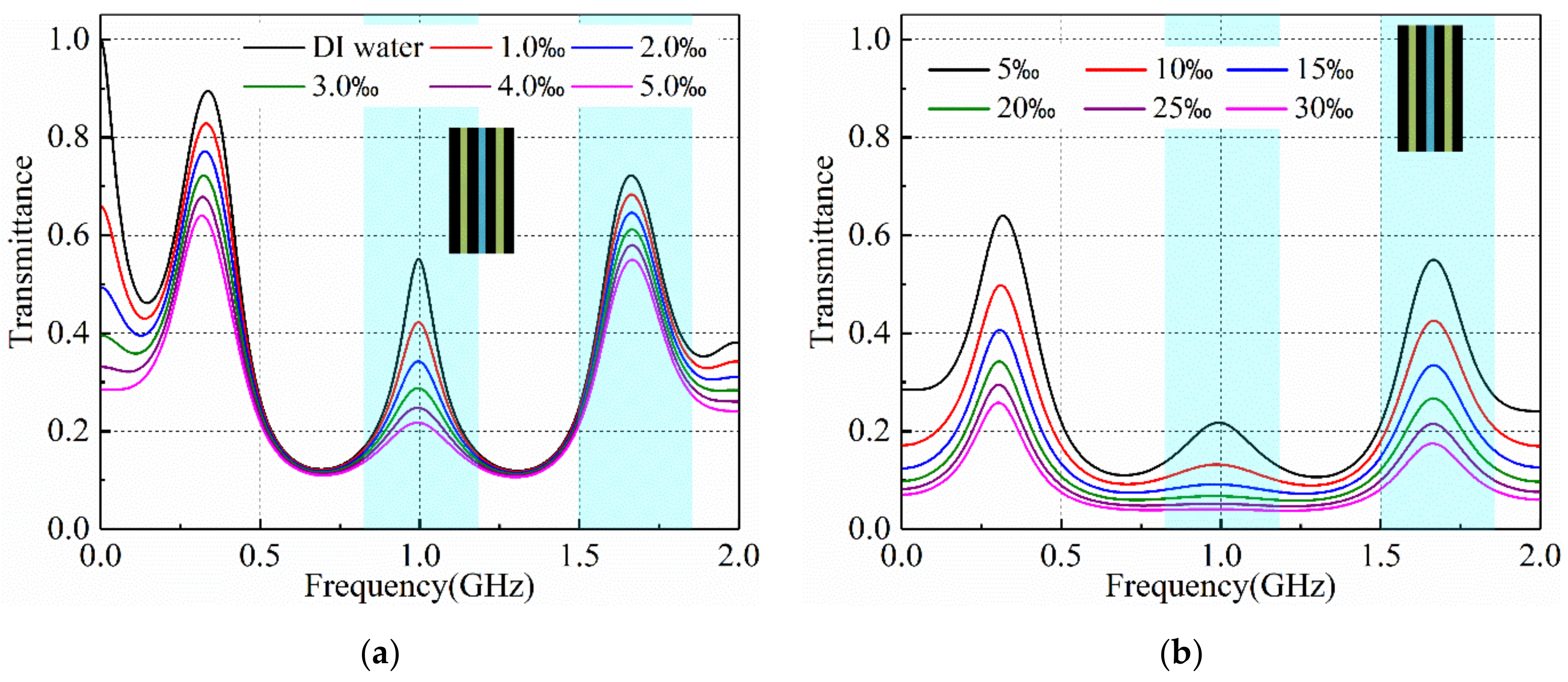
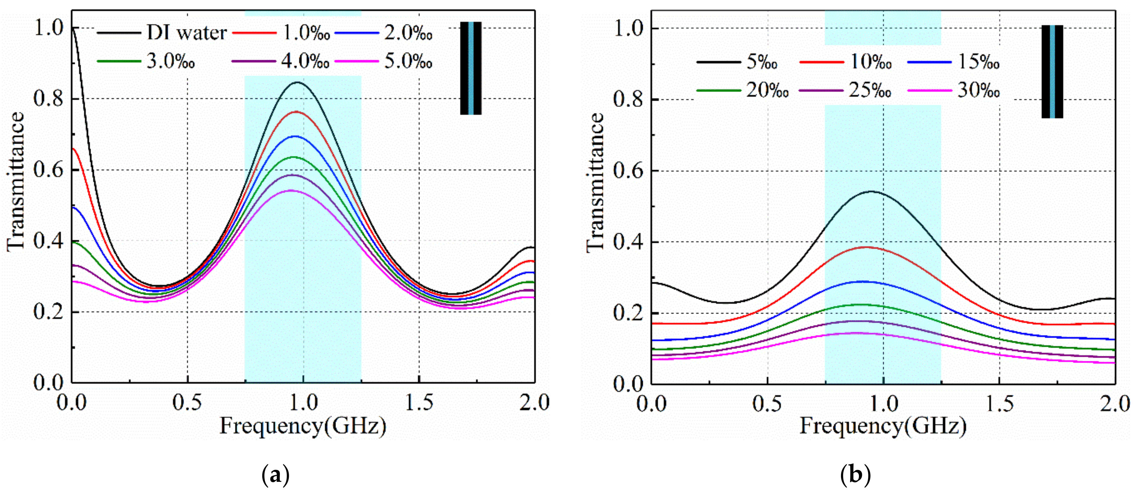
2.2. Defective Microwave Photonic Crystal Design

The concept of photonic crystals was established by Yablonovitch and John in 1987 [42]. It was found that the propagation of electromagnetic waves can be controlled by making repetitions of the different dielectric materials in a periodic structure. The one-dimensional MPCs are designed by periodically stacking 2 contrasting dielectric materials in a microwave wavelength scale [43]. A defective layer can be introduced within a one-dimensional MPC to generate defective resonance. In the optical frequency regime, the defective resonance has been used to detect the salinity of saline solution [31,32], where the principle is based on the fact that the concentration of the salinity in the salt solution changes the optical refractive index. The salinity sensitivity was calculated by a peak wavelength shift happening in the transmittance spectrum for its variation of different salt concentrations of samples. In this work, one-dimensional defective MPC structures are also designed. Two commonly used good microwave dielectric materials (Rogers 5880 and 6010, Rogers Corporation, Chandler, AZ, USA) are utilized to configurate the MPC structures, and the saline solution is confined within a defective chamber layer. The schematic diagram of the proposed one-dimensional defective MPC structure is shown in Figure 1, where A stands for the Rogers 5880 layer with a dielectric constant ( ε A ) of 2.2 and loss tangent of 0.0009, B represents the Rogers 6010 layer with a dielectric constant ( ε B ) of 10.2 and loss tangent of 0.0023, and C is the saline solution layer under salinity sensing. All 3 constituent layers of the MPC sensor are regarded as nonmagnetic materials ( μ A = μ B = μ C = 1.0 ). The thicknesses of the 3 layers fulfill the Bragg scattering condition and condition of defective resonance at central frequency: d A = λ 0 / 4 ε A , d B = λ 0 / 4 ε B and d C = λ 0 / 2 ε C , where λ 0 is the central working wavelength of the MPC structures. In the microwave regime, the transmission spectrum of the MPC structure can be obtained by measuring scattering parameter S21, which is defined as the transmission coefficients from the transmitting antenna to the receiving antenna under the condition that the receiving antenna is matched by using a vector network analyzer (VNA). The calibration of the transmission spectrum can be carried out by testing the S21 with an empty space. In this work, the sensing principle and the detection process are accomplished by using the transfer matrix method (TMM) for lossy medium.

2.3. Transfer Matrix Method for Lossy Medium

Consider that defective MPC sensors located in the far-field zone of the transmitting antenna and the transmitting wave can be regarded as plane waves with transverse electric field E x and transverse magnetic field H y propagating along a longitudinal ( + z ) direction. The field equations in the form of a transmission line equation are given as:
d E x d z = z ^ ( ω ) H y
d H y d z = y ^ ( ω ) E x
Here, z ^ ( ω ) and y ^ ( ω ) are the impedivity and admittivity of the constituent medium, respectively, which specify the characteristics of the medium and correspond to the admittance and impedance in the per length of the transmission line. For all the constituent materials of the MPC structure, the impedivity and admittivity can be expressed in the general form of y ^ ( ω ) = j ω ε ^ ( ω ) and z ^ ( ω ) = j ω μ ^ ( ω ) , where ε ^ ( ω ) and μ ^ ( ω ) are the complex permittivity and permeability of the materials, respectively. As a result, the intrinsic wave number (propagation constant) of the constituent materials is given as k ( ω ) = z ^ ( ω ) y ^ ( ω ) . Using the condition of continuity of the tangential electrical field, the electromagnetic waves on the boundaries of the i-th layer are related through its transfer matrix:
E x ( z + d i , ω ) j H y ( z + d i , ω ) = cos ( k ^ i d i ) ω μ 0 sin ( k ^ i d i ) / k ^ k ^ sin ( k ^ i d i ) / ω μ 0 cos ( k ^ i d i ) E x ( z , ω ) j H y ( z , ω )
The total transfer matrix for the multilayered defective MPC sensors is expressed as:
X ( ω ) = i = 1 N = 3 M ( d i , ω )
Based on the definition of reflection and transmission coefficients, they can be expressed as:
r ( ω ) = X 22 ( ω ) X 11 ( ω ) j X 21 ( ω ) ω μ 0 k 0 + X 12 ( ω ) k 0 ω μ 0 X 22 ( ω ) + X 11 ( ω ) + j X 21 ( ω ) ω μ 0 k 0 + X 12 ( ω ) k 0 ω μ 0
t ( ω ) = 2 X 22 ( ω ) + X 11 ( ω ) + j X 21 ( ω ) ω μ 0 k 0 + X 12 ( ω ) k 0 ω μ 0
Using Equation (9), one can calculate the transmission spectrum of a one-dimensional defective MPC sensor, which is used to extract the salinity of the aqueous solution confined within the defective layer.

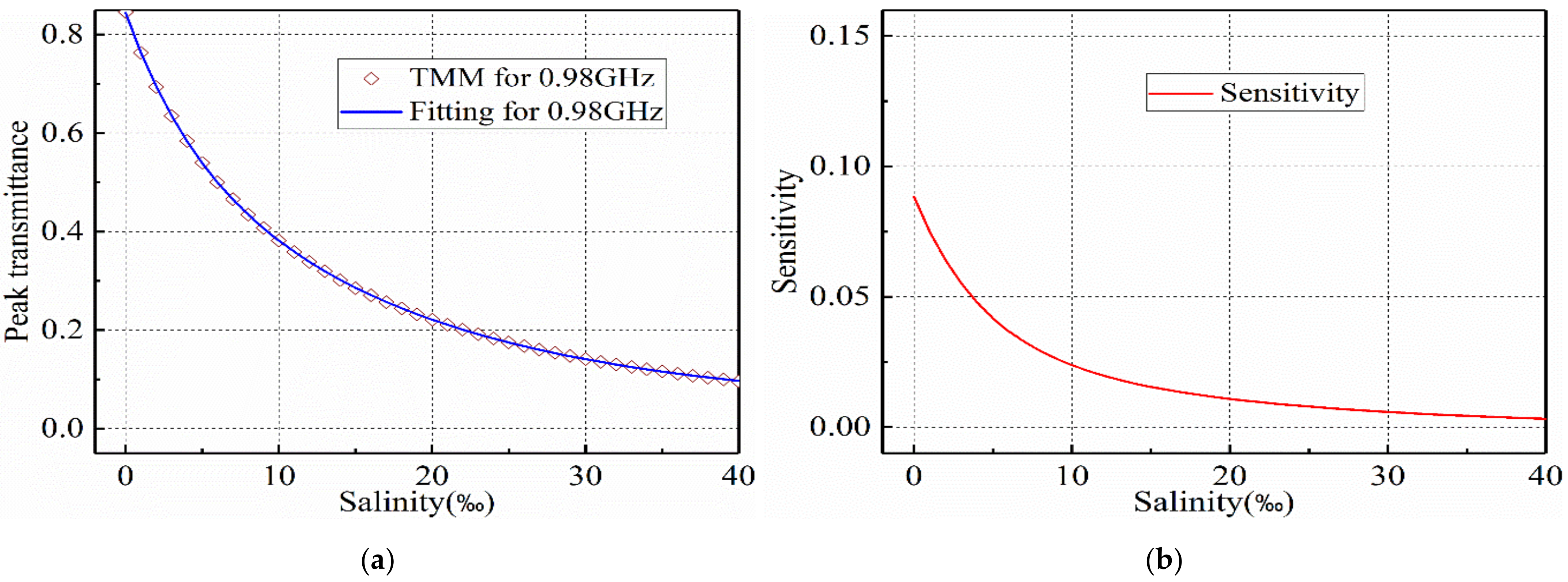
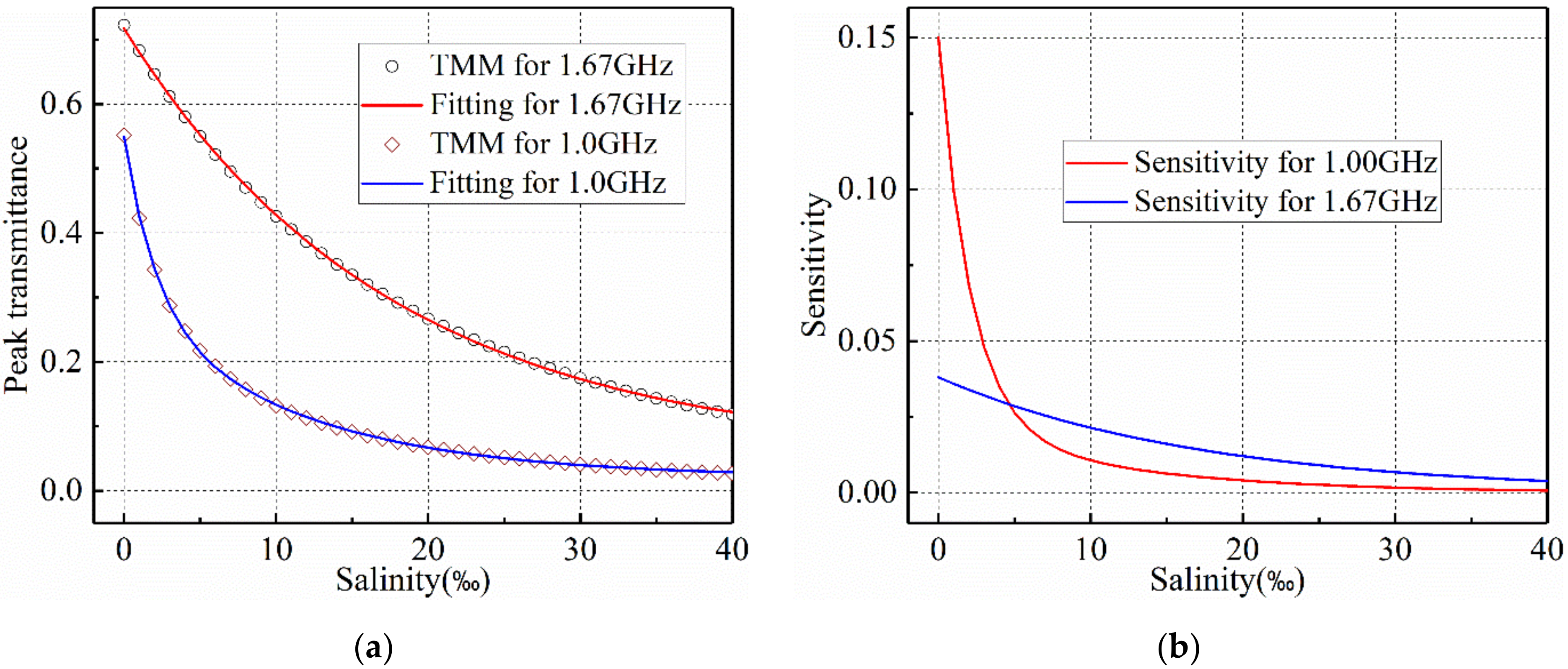
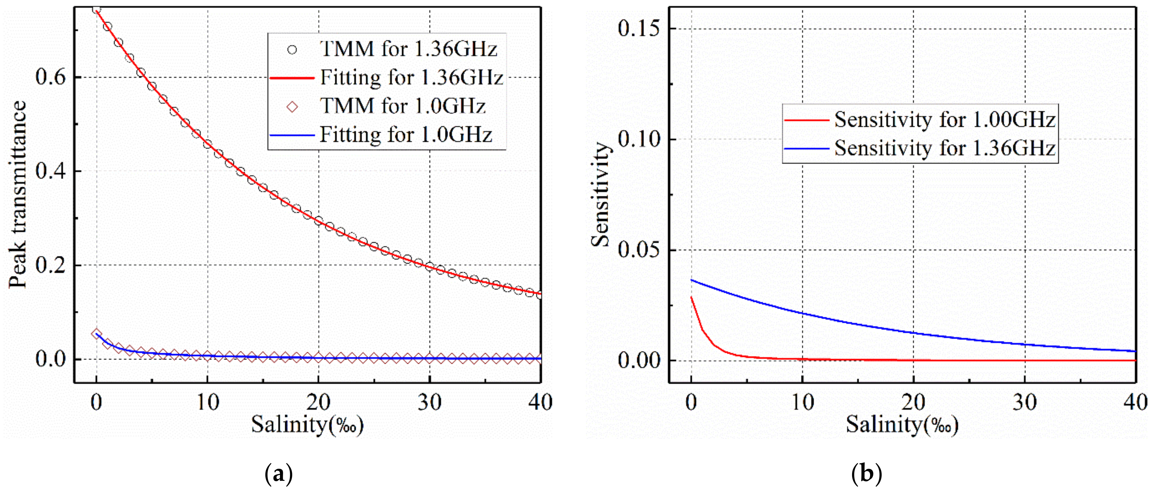
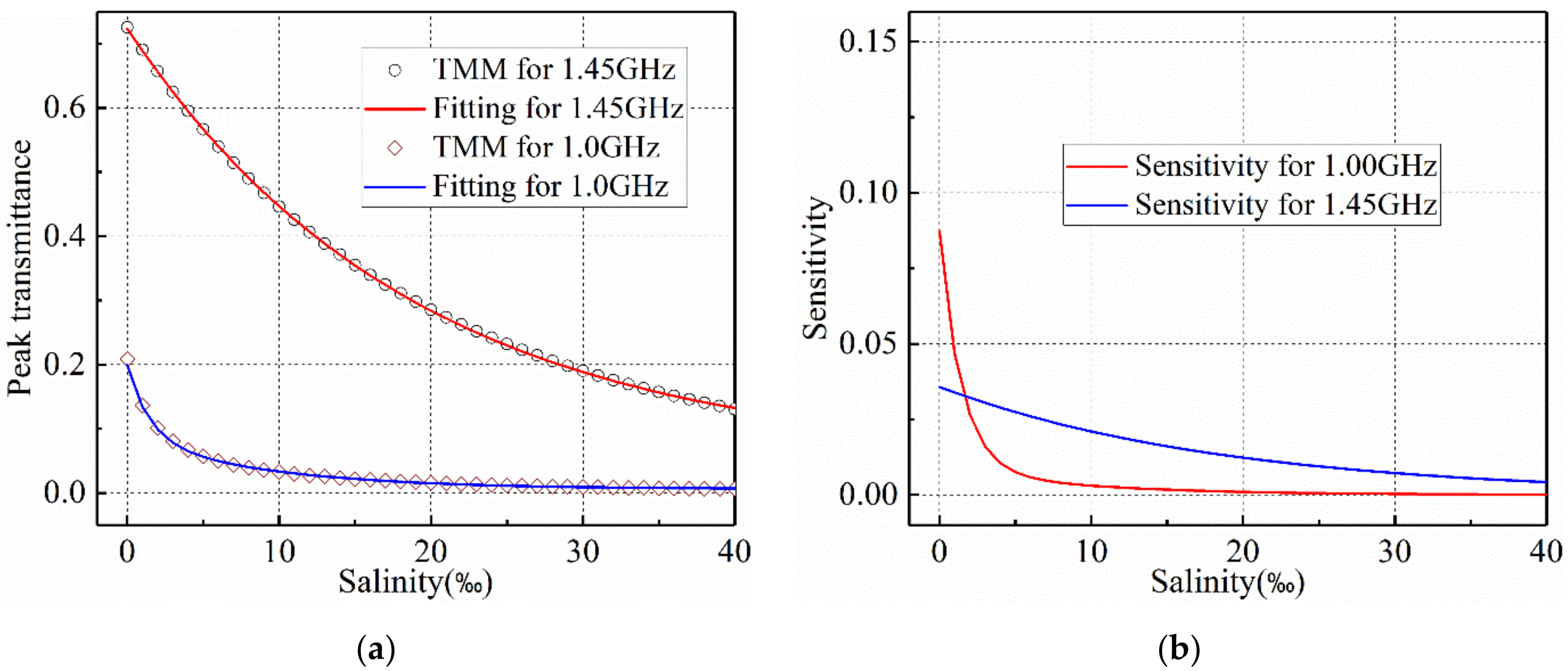
2.4. Detecting Sensitivity

The proposed sensing technique is based on the variation of dielectric loss in the microwave frequency regime with a change of salinity, which makes the resonant transmittance vary with salinity. Hence, the detecting sensitivity is defined as the ratio between variations in the peak transmittance and in the salinity of the saline solution:
S e n s i t i v i t y = Δ t peak Δ S

2.5. Quality Factor

The quality factor (Q-factor) of the resonance of a one-dimensional defective MPC sensor is another important parameter for spectrum measurement, and it is defined as the ratio between the central wavelength of the resonance and its full width at half maximum:
Q = λ p e a k Δ λ

3. Results

3.1. Microwave Dielectric Properites of Salt Solution

Considering the reported defective MPC sensors work at room temperature (20 °C), the complex permittivity of the saline solution is plotted in Figure 2 by using the regression equations provided in the Klein and Swift model [40].
Taking the working frequency of the MPC sensors to be 1.0 GHz, the simulation frequency band ranges from 0.2 to 2.0 GHz. The dielectric constant of the saline solution decreases very slowly with the increase of salinity in this frequency band. However, the dielectric loss observably increases with the increase of salinity in the entire frequency region. The dielectric loss of the saline solution results in the absorption of the propagating wave through the MPC sensor, and the almost unchanged dielectric constant causes the resonant frequencies to remain unchanged.

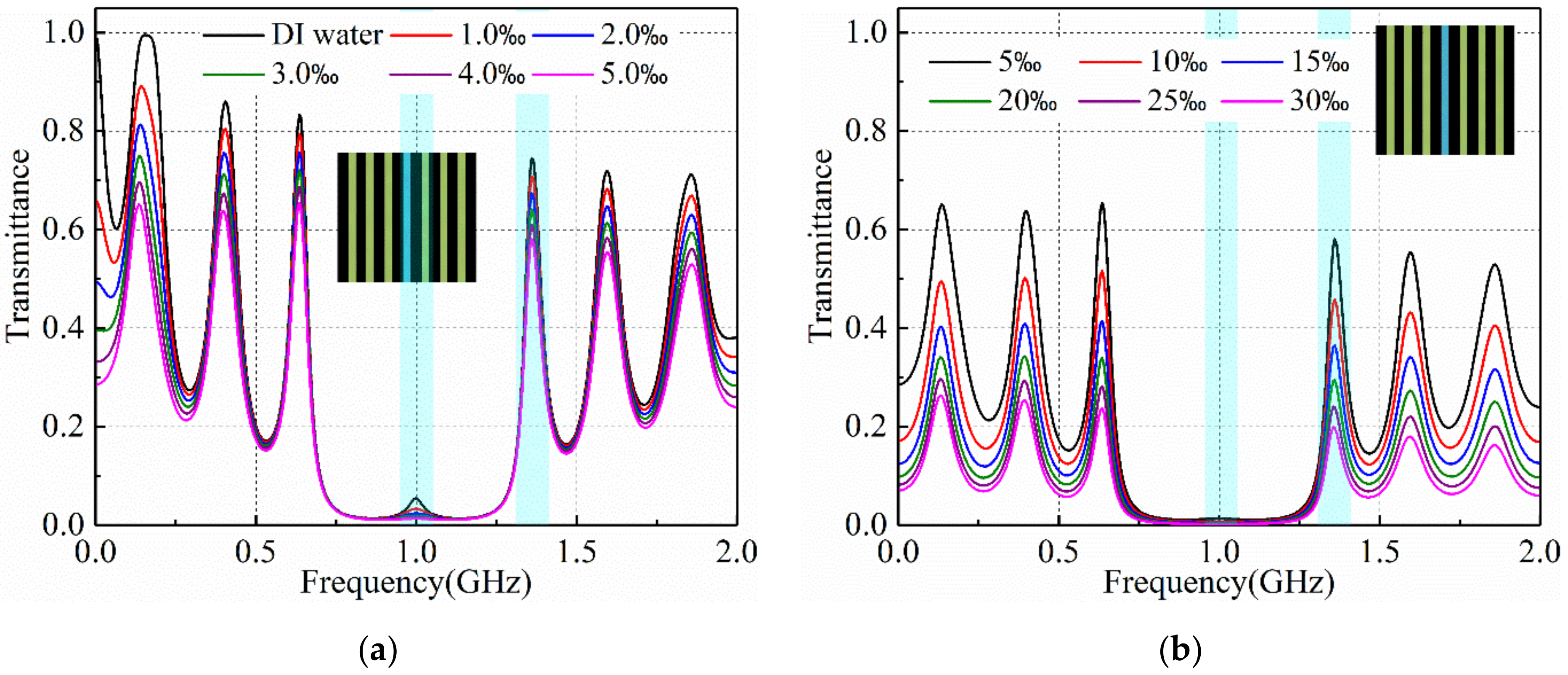
3.2. Salinity Sensoring Results

At first, considering the condition of the multiple Bragg scattering and the total size of the defective MPC sensor, an 11-layer structure (ABABACABABA) is constructed to form a stop band, which is called a microwave band gap (MBG), and a defective resonance. The transmittance spectra with different salt concentrations are calculated by using TMM for lossy medium and are plotted in Figure 3. When the defective layer is configurated with DI water (salinity of zero), an MBG ranging from 0.6 to 1.4 GHz is observed with a defective resonance at the central frequency at 1.0 GHz, as shown in Figure 3a. In addition, there are another four transmitting modes outside the MBG frequency band. The defective resonant peak transmittance dramatically decreases with the increase of salinity. When the salinity is zero (DI water), the defective resonant peak transmittance is approximately 0.21, and it almost disappears when the salinity reaches up to 10‰, as shown in Figure 3b. Hence, the sensing range is limited by detecting the defective resonant peak transmittance. By observing and comparing the other four transmitting mode peaks outside the MBG frequency band, it is found that the first one in the upper frequency band outside the MBG has a higher quasi- or quality factor and keeps the transmitting mode frequency very stable at 1.45 GHz. Therefore, it is the best to be utilized to sense the salinity by detecting the peak transmittance strength.
As mentioned above, salinity sensing can be realized by detecting both the defective resonance and transmitting modes outside the MBG. The variation of the defective resonant transmittance is more sensitive to the variation of salinity in the low concentration of saline solution, but the detecting range is very limited. In order to enlarge the salinity sensing range, the defective resonance can be weakened by reducing the periodicity of the MPC sensor. The transmittance spectra of the 7-layer structure (ABACABA) with different salt concentrations are plotted in Figure 4, where the defective MPC structure is seen in the inset. When the defective layer is configurated with DI water (salinity of zero), the MBG remains almost unchanged and the defective resonance peak transmittance is approximately 0.55, as shown in Figure 4a. The defective resonant peak disappears when the salinity reaches up to 25‰, as shown in Figure 4b. By further reducing the number of layers, the defective MPC structure comes to be a Fabry-Perot cavity structure (ACA), as shown in the inset in Figure 5. In this case, there is only one resonance at 0.98 GHz and the transmitting modes disappear, which can be regarded as the prototype of the defective resonance for the defective MPC sensors. When the cavity layer is reconfigured with DI water (salinity of zero), the resonant peak transmittance reaches up to 0.85, as shown in Figure 5a. The resonant peak transmittance decreases with the increase of salinity in a range of 0 to 40‰, as shown in Figure 5b. It is found that both the transmittance and its full width at half maximum of the resonance become large, indicating that the sensing range is expanded but the Q-factor becomes small.
Taking the first transmitting mode upper outside the MBG as the salinity detecting scheme, it has a larger sensing range when compared with that by detecting the defective resonance. In order to enhance the quasi-quality factor of the transmission modes outside the MBG frequency band, which can be defined using Equation (11) as well, the number of the layers for the defective MPC is increased to 15. The transmittance spectra at different salt concentrations are calculated by using TMM for lossy medium, as shown in Figure 6. It can be seen that the defective resonance is further suppressed at the central frequency and the quasi-quality factor of the transmitting modes outside the MBG is enhanced. As shown in Figure 6a, the first transmitting mode in the upper frequency band outside the EBG occurs at 1.36 GHz. Its transmittance decreases with the increase of the salinity of the saline solution, as shown in Figure 6a,b. In contrast, quasi- and quality factors of the defective resonant peak and the first transmitting mode peak upper outside the MBG for the four multilayered sensing structures with DI water configured in the defective layer are calculated based on Equation (8) and listed in Table 1. It is found that the quasi- and quality factors of both the defective resonance and transmitting mode are increased by adding the layers of the MPC structure. The first transmitting mode peak for the 15-layer defective MPC sensing structure has the highest quasi-quality factor of 21.143. Hence, it is the best transmitting mode to be used to sense the salinity of the salt solution. By increasing the salinity of saline solution, the full width at half maximum is increased, which results in the decrease of the quasi-quality factor.
To determine the relationship between the resonant peak transmittance of defective resonance or transmitting mode and salinity, the peak transmittance is calculated by using TMM at discrete salinity values. Representation functions for each resonant peak transmittance are developed in terms of the so-called Prony series [44]:
t p e a k ( S ) = i = 1 N a i e b i S
The fitting coefficients can be optimized by utilizing the Levenberg-Marquardt Algorithm [45]. As shown in Figure 7a, there is one Fabry-Perot resonance for the 3-layer salinity sensor and its transmittance curve versus salinity is fitted by function:
t p e a k ( S ) = 0.2343 e 0.2354 S + 0.569 e 0.05828 S + 0.04169
For the 7-layer defective MPC structure, the defective resonant peak transmittance at 1.0 GHz and the first transmitting mode peak transmittance at 1.67 GHz versus salinity are fitted by functions:
t p e a k ( S ) = 0.2655 e 0.4788 S + 0.2635 e 0.08687 S + 0.02052
t peak ( S ) = 0.6618 e 0.05752 S + 0.05566
The peak transmittance versus salinity is calculated by TMM for lossy medium and the fitting curve are plotted in Figure 8a. In the low salinity range, the defective resonant peak transmittance decreases faster than that of the first transmitting mode with the increase of salinity. However, in the high salinity range, the defective resonant peak transmittance decreases more slowly than that of the first transmitting mode with the increase of salinity, which indicates that the defective resonance has a larger transmittance detecting sensitivity only in the low salinity range.
By increasing the number of defective MPC sensor layers, the defective resonant peak transmittance at 1.0 GHz is further suppressed. The defective resonant peak transmittance at 1.0 GHz and the first transmitting mode peak transmittance at 1.45 GHz versus salinity for the 11-layer defective MPC sensor are fitted by functions:
t peak ( S ) = 0.1221 e 0.7008 S + 0.08102 e 0.1092 S + 0.006134
t p e a k ( S ) = 0.6710 e 0.05311 S + 0.05282
The peak transmittance calculated by TMM for lossy medium and fitted functions are plotted in Figure 9a, and they are in good agreement as well. For the 15-layer defective MPC sensor, the defective resonant peak transmittance at 1.0 GHz and the first transmitting mode peak transmittance at 1.36 GHz versus salinity are fitted by functions:
t p e a k ( S ) = 0.1221 e 0.7008 S + 0.08102 e 0.1092 S + 0.006134
t p e a k ( S ) = 0.6710 e 0.05311 S + 0.05282
As shown in Figure 10a, the peak transmittance calculated by TMM for lossy medium and fitted functions are in good agreement.
Finally, the detecting sensitivity of the peak transmittance versus salinity is calculated for the four defective MPC sensors, as shown in Figure 7b, Figure 8b, Figure 9b and Figure 10b, respectively. It can be seen that the detecting sensitivity of the defective resonance is larger than that of the first transmitting mode in the upper frequency band outside the MBG for the 7-layer and 11-layer defective MPC sensors. By increasing the number of MPC sensor layers to 15, the defective resonance is badly suppressed in the total range of salinity. Hence, the sensitivity of defective resonance is always lower than that of the first transmission mode.

4. Discussion

The salinity-sensing principle is based on the resonance of one-dimensional defective MPC structures. The defective resonance within the MBG frequency band and the transmitting modes outside the MBG frequency band are the two most important properties of defective MPCs. When the defective layer is configured with saline solution under salinity sensing, the frequencies of the defective resonance and transmitting modes remain almost unchanged with the variation of salinity, but the resonant transmittance monotonously decreases with the increase of salinity. Such a phenomenon attributes to the fact that the dielectric constant is insensitive to the variation of salinity, while the dielectric loss obviously decreases with the increase of salinity. The salinity can be sensed by detecting both the transmittance of defective resonance and the first transmitting mode in the upper frequency band outside the MBG. As the defective resonance is realized by the cavity bound, the cavity-confined wave energy is more likely to be absorbed. Hence, the sensing range of salinity is limited by detecting the defective resonance, but it has a larger detecting sensitivity in the low salinity range. When the defective resonance is weakened by reducing the number of defective MPC layers, the salinity sensing range can be expanded. In contrast, the detecting sensitivity of the first transmitting mode slowly decreases with the increase of salinity, which makes it have a larger salinity sensing range. The quality factor of the defective resonance and quasi-quality factor of the first transmitting mode can be increased by increasing the layers of the defective MPC sensor.

5. Conclusions

In this paper, we theoretically demonstrated a concept of salinity sensor by using one-dimensional defective MPC structures. The salinity of saline solution can be sensed by detecting the transmittance of both the defective resonance within the MBG frequency band and the first transmitting mode in the upper frequency band outside the MBG. The defective resonance has a higher detecting sensitivity but a limited sensing range in the low salinity range. By comparing the four reported MPC sensors, the first transmitting mode in the upper frequency band outside the MBG of the 15-layer MPC sensor operates the largest salinity sensing range from 0 to 40‰ with relative stable detecting sensitivity. The quality factor of the defective resonance and quasi-quality factor of the first transmitting mode can be increased by increasing the periodicity of the defective MPC sensor.

Author Contributions

Conceptualization, Y.Z. and H.Y.; methodology, Y.Z. and H.Y.; software, Y.Z.; validation, Y.Z. and H.Y.; formal analysis, Y.Z.; investigation, Y.Z.; resources, H.Y.; data curation, Y.Z. and H.Y.; writing—original draft preparation, Y.Z.; writing—review and editing, Y.Z. and H.Y.; visualization, Y.Z.; supervision, H.Y.; project administration, Y.Z.; funding acquisition, Y.Z. All authors have read and agreed to the published version of the manuscript.

Funding

This research was funded by the National Key R & D Program of China (2019YFC1606200).

Institutional Review Board Statement

Not applicable.

Informed Consent Statement

Not applicable.

Data Availability Statement

No new data were created or analyzed in this study. Data sharing is not applicable to this article.

Conflicts of Interest

The authors declare no conflict of interest.

References

  1. Durack, E.; Alonso-Gomez, M.; Wilkinson, M.G. Salt: A review of its role in food science and public health. Curr. Nutr. Food Sci. 2008, 4, 290–297. [Google Scholar] [CrossRef]
  2. Harnsoongnoen, S.; Wanthong, A. A non-contact planar microwave sensor for detection of high-salinity water containing NaCl, KCl, CaCl2, MgCl2 and Na2CO3. Sens. Actuators B Chem. 2021, 331, 129355. [Google Scholar] [CrossRef]
  3. Islam, M.T.; Rahman, M.N.; Singh, M.S.J. Detection of salt and sugar contents in water on the basis of dielectric properties using microstrip antenna-based sensor. IEEE Access 2018, 6, 4118–4126. [Google Scholar] [CrossRef]
  4. GB 2760–2014 (2014) National Food Safety Standard, Standards for the Use of Food Additives; National Health and Family Planning Commission of the People’s Republic of China & China Food and Drug Administration: Beijing, China, 2014.
  5. Li, X.B.; Kang, Y.H. Agricultural utilization and vegetation establishment on saline-sodic soils using a water–salt regulation method for scheduled drip irrigation. Agric. Water Manag. 2020, 231, 105995. [Google Scholar] [CrossRef]
  6. Chiang, C.T.; Chang, C.W. Design of a calibrated salinity sensor transducer for monitoring salinity of ocean environment and aquaculture. IEEE Sens. J. 2015, 15, 5151–5157. [Google Scholar] [CrossRef]
  7. You, B.; Yue, Y.D.; Sun, M.X.; Li, J.Y.; Jia, D.L. Design of a real-time salinity detection system for water injection wells based on fuzzy control. Sensors 2021, 21, 3086. [Google Scholar] [CrossRef]
  8. Stadler, A. Analyzing UV/Vis/NIR spectra—Correct and efficient parameter extraction. IEEE Sens. J. 2010, 10, 1921–1931. [Google Scholar] [CrossRef]
  9. Stadler, A. Analyzing UV/Vis/NIR spectra—Part II: Correct and efficient parameter extraction. IEEE Sens. J. 2011, 11, 897–904. [Google Scholar] [CrossRef]
  10. Kapilevich, B.; Litvak, B. Optimized microwave sensor for online concentration measurements of binary liquid mixtures. IEEE Sens. J. 2011, 11, 2611–2616. [Google Scholar] [CrossRef]
  11. Diamond, J.M. An inductive conductivity meter for monitoring the salinity of dialysis Water. IEEE Trans. Biomed. Eng. 1970, 17, 109–117. [Google Scholar] [CrossRef] [PubMed]
  12. Hyldgard, A.; Mortensen, D.; Birkelund, K.; Hansen, O.; Thomsen, E.V. Autonomous multi-sensor micro-system for measurement of ocean water salinity. Sens. Actuators A Phys. 2008, 147, 474–484. [Google Scholar] [CrossRef]
  13. Huang, X.; Pascal, R.W.; Chamberlain, K.; Banks, C.J.; Mowlem, M.; Morgan, H. A Miniature, high precision conductivity and temperature sensor system for ocean monitoring. IEEE Sens. J. 2011, 11, 3246–3252. [Google Scholar] [CrossRef]
  14. Cong, J.; Zhang, X.M.; Chen, K.S.; Xu, J. Fiber optic Bragg grating sensor based on hydrogels for measuring salinity. Sens. Actuators B Chem. 2002, 87, 487–490. [Google Scholar] [CrossRef]
  15. Kauffmann, T.H.; Fontana, M.D. Optical sensor of salt concentration: Uncertainty evaluation. Sens. Actuators B Chem. 2012, 161, 21–27. [Google Scholar] [CrossRef]
  16. Yin, Y.; Li, S.; Ren, J.; Farrell, G.; Lewis, E.; Wang, P. High-sensitivity salinity sensor based on optical microfiber coil resonator. Opt. Express 2018, 26, 34633–34640. [Google Scholar] [CrossRef] [Green Version]
  17. Yang, H.Z.; Qiao, X.G.; Lim, K.S.; Harun, S.W.; Chong, W.Y.; Islam, M.R.; Ahmad, H. Optical fiber sensing of salinity and liquid level. IEEE Photonics Technol. Lett. 2014, 26, 1742–1745. [Google Scholar] [CrossRef]
  18. Durickovic, I.; Marchetti, M.; Claverie, R.; Bourson, P.; Chassot, J.M. Experimental study of NaCl aqueous solutions by Raman spectroscopy: Towards a new optical sensor. Appl. Spectrosc. 2010, 64, 853–857. [Google Scholar] [CrossRef]
  19. Kleis, S.J.; Sanchez, L.A. Dependence of sound velocity on salinity and temperature in saline solutions. Sol. Energy 1991, 46, 371–375. [Google Scholar] [CrossRef]
  20. Cheng, E.M.; Fareq, M.; Shahriman, A.B.; Mohd Afendi, R.; Lee, Y.S.; Khor, S.F.; Tan, W.H.; Nashrul Fazli, M.N.; Abdullah, A.Z.; Jusoh, M.A. Development of microstrip patch antenna sensing system for salinity and sugar detection in water. Int. J. Mech. Mechatron. Eng. 2014, 15, 31–36. [Google Scholar]
  21. Rahman, M.N.; Hassan, S.A.; Samsuzzaman, M.; Singh, M.S.J.; Islam, M.T. Determination of salinity and sugar concentration using microwave sensor. Microw. Opt. Technol. Lett. 2019, 61, 361–364. [Google Scholar] [CrossRef]
  22. Harnsoongnoen, S.; Wanthong, A.; Charoen-In, U.; Siritaratiwat, A. Planar microwave sensor for detection and discrimination of aqueous organic and inorganic solutions. Sens. Actuators B Chem. 2018, 271, 300–305. [Google Scholar] [CrossRef]
  23. Kilpijärvi, J.; Halonen, N.; Juuti, J.; Hannu, J. Microfluidic microwave sensor for detecting saline in biological range. Sensors 2019, 19, 819. [Google Scholar] [CrossRef] [Green Version]
  24. Wang, J.Y.; Chen, B.X. Experimental research of optical fiber sensor for salinity measurement. Sens. Actuators A Phys. 2012, 184, 53–56. [Google Scholar] [CrossRef]
  25. Rahman, H.A.; Harun, S.W.; Yasin, M.; Phang, S.W.; Damanhuri, S.S.A.; Arof, H.; Ahmad, H. Tapered plastic multimode fiber sensor for salinity detection. Sens. Actuators A Phys. 2011, 171, 219–222. [Google Scholar] [CrossRef]
  26. Wu, C.; Guan, B.O.; Lu, C.; Tam, H.Y. Salinity sensor based on polyimide-coated photonic crystal fiber. Opt. Express 2011, 19, 20003–20008. [Google Scholar] [CrossRef] [PubMed] [Green Version]
  27. Vigneswarana, D.; Ayyanarb, N.; Sharmac, M.; Sumathib, M.; Rajand, M.S.M.; Porsezian, K. Salinity sensor using photonic crystal fiber. Sens. Actuators A Phys. 2018, 269, 22–28. [Google Scholar] [CrossRef]
  28. Amiri, I.S.; Paul, B.K.; Ahmed, K.; Aly, A.H.; Zakzria, R.; Yupapin, P.; Vigneswaran, D. Tri-core photonic crystal fiber based refractive index dual sensor for salinity and temperature detection. Microw. Opt. Technol. Lett. 2019, 61, 847–852. [Google Scholar] [CrossRef]
  29. Ramya, K.C.; Monfared, Y.E.; Maheswar, R.; Dhasarathan, V. Dual-core twisted photonic crystal fiber salinity sensor: A numerical investigation. IEEE Photonics Technol. Lett. 2020, 32, 616–619. [Google Scholar] [CrossRef]
  30. Zhang, Y.; Xie, X.; Yang, Z.K.; Hao, J.J.; Xu, Z.G.; Yang, H.W. Study on the spectrum of photonic crystal cavity and its application in measuring the concentration of NaCl Solution. Z. Nat. A J. Phys. Sci. 2017, 72, 345–349. [Google Scholar] [CrossRef]
  31. Ben Ali, N.; Alsaif, H.; Trabelsi, Y.; Chughtai, M.T.; Dhasarathan, V.; Kanzari, M. High sensitivity to salinity-temperature using one-dimensional deformed photonic crystal. Coatings 2021, 11, 713. [Google Scholar]
  32. Qutb, S.R.; Aly, A.H.; Sabra, W. Salinity and temperature detection for seawater based on a 1d-defective photonic crystal material. Int. J. Mod. Phys. B 2021, 35, 2150012. [Google Scholar] [CrossRef]
  33. Sayed, H.; Aly, A.H. Salinity optical sensor by using two-dimensional photonic crystals: Computational study. Mater. Sci. Eng. B 2021, 269, 115169. [Google Scholar] [CrossRef]
  34. Zaky, Z.A.; Aly, A.H. Highly sensitive salinity and temperature sensor using tamm resonance. Plasmonics 2021. early access. [Google Scholar] [CrossRef]
  35. Lee, K.; Hassan, A.; Lee, C.H.; Bae, J. Microstrip patch sensor for salinity determination. Sensors 2017, 17, 2941. [Google Scholar] [CrossRef] [PubMed] [Green Version]
  36. Velez, P.; Grenier, K.; Mata-Contreras, J.; Dubuc, D.; Martín, F. Highly-sensitive microwave sensors based on open complementary split ring resonators (OCSRRs) for dielectric characterization and solute concentration measurement in liquids. IEEE Access 2018, 6, 48324–48338. [Google Scholar] [CrossRef]
  37. Velez, P.; Munoz-Enano, J.; Grenier, K.; Mata-Contreras, J.; Dubuc, D.; Martín, F. Split ring resonator-based microwave fluidic sensors for electrolyte concentration measurements. IEEE Sens. J. 2019, 19, 2562–2569. [Google Scholar] [CrossRef]
  38. Chudpooti, N.; Duangrit, N.; Sangpet, P.; Akkaraekthalin, P.; Imberg, B.U.; Robertson, I.D.; Somjit, N. In-situ self-aligned NaCl-solution fluidic-integrated microwave sensors for industrial and biomedical applications. IEEE Access 2020, 8, 188897–188907. [Google Scholar] [CrossRef]
  39. Stogryn, A. Equations for calculating the dielectric constant of saline water. IEEE Trans. Microw. Theory Tech. 1971, 19, 733–736. [Google Scholar] [CrossRef]
  40. Klein, L.; Swift, C. An improved model for the dielectric constant of sea water at microwave frequencies. IEEE Trans. Antennas Propag. 1977, 25, 104–111. [Google Scholar] [CrossRef]
  41. Gadani, D.H.; Rana, V.A.; Bhatnagar, S.P.; Prajapati, A.N.; Vyas, A.D. Effect of salinity on the dielectric properties of water. Indian J. Pure Appl. Phys. 2012, 50, 405–410. [Google Scholar]
  42. John, S. Strong localization of photons in certain disordered dielectric superlattices. Phys. Rev. Lett. 1987, 58, 2486. [Google Scholar] [CrossRef] [PubMed] [Green Version]
  43. Wang, S.Y.; Liu, S.B. Tunable filter using plasma defect in one-dimensional microwave photonic crystal. Acta Phys. Sin. 2009, 58, 7062–7066. [Google Scholar]
  44. Delfino, F.; Procopio, R.; Rossi, M.; Rachidi, F. Prony series representation for the lightning channel base current. IEEE Trans. Electromagn. Compat. 2012, 54, 308–315. [Google Scholar] [CrossRef]
  45. Nocedal, J.; Wright, S.J. Numerical Optimization; Springer: Berlin/Heidelberg, Germany, 1999. [Google Scholar]
Figure 1. Schematic showing of the defective microwave photonic crystals.
Coatings 11 01243 g001
Figure 2. The complex permittivity of the saline solution at room temperature.
Coatings 11 01243 g002
Figure 3. The transmittance spectra of the 11-layer defective MPC sensor with a salinity range of (a) 0–5‰, (b) 5–30‰.
Coatings 11 01243 g003
Figure 4. The transmittance spectra of the 7-layer defective MPC sensor with salinity range of (a) 0–5‰, (b) 5–30‰.
Coatings 11 01243 g004
Figure 5. The transmittance spectra of the 3-layer defective MPC sensor with a salinity range of (a) 0–5‰, (b) 5–30‰.
Coatings 11 01243 g005
Figure 6. The transmittance spectra of the 15-layer defective MPC sensor with a salinity range of (a) 0–5‰, (b) 5–30‰.
Coatings 11 01243 g006
Figure 7. (a) Peak transmittance of the Fabry-Perot cavity resonance, and (b) the detecting sensitivity of the peak transmittance versus salinity for the 3-layer Fabry-Perot cavity sensor.
Coatings 11 01243 g007
Figure 8. (a) Peak transmittance of the defective resonance and the first transmitting mode, and (b) the detecting sensitivity of the peak transmittance versus salinity for the 7-layer defective MPC sensor.
Coatings 11 01243 g008
Figure 9. (a) Peak transmittance of the defective resonance and first transmitting mode, and (b) the detecting sensitivity of the peak transmittance versus salinity for the 11-layer defective MPC sensor.
Coatings 11 01243 g009
Figure 10. (a) Peak transmittance of the defective resonance and first transmitting mode, and (b) the detecting sensitivity of the peak transmittance versus salinity for the 15-layer defective MPC sensor.
Coatings 11 01243 g010
Table 1. Quasi- and quality factors of the defective resonance and first transmitting mode for the four detective MPC sensors under DI water configured within the defective layer.
Sensor StructureDefective Resonance1st Transmitting Mode
ACA1.364-
ABACABA5.3325.612
ABABACABABA10.34512.146
ABABABACABABABA11.08921.143
Publisher’s Note: MDPI stays neutral with regard to jurisdictional claims in published maps and institutional affiliations.

